


Altivar® 31
Adjustable Speed Drive Controllers
Variadores de velocidad ajustable
Variateurs de vitesse
Programming Manual
Manual de programación
Guide de programmation
Retain for future use. / Conservar para uso futuro. /
À conserver pour usage ultérieur.

Altivar® 31 Adjustable Speed Drive Controllers
Programming Manual . . . . . . . . . . . . . . . . . . . . . . . . . 5
Variadores de velocidad Ajustable Altivar® 31
Manual de programación . . . . . . . . . . . . . . . . . . . . . .99
Variateurs de vitesse Altivar® 31
Guide de programmation . . . . . . . . . . . . . . . . . . . . 193
ENGLISH
ESPAÑOL
FRANÇAIS
© 2004 Schneider Electric All Rights Reserved |
3 |

ENGLISH
ESPAÑOL
FRANÇAIS
4 |
© 2004 Schneider Electric All Rights Reserved |

VVDED303042NAR6/04 |
Altivar® 31 Programming Manual |
|
06/2004 |
|
Contents |
|
|
|
SECTION 1: INTRODUCTION |
Product Range ............................................................................................ |
7 |
|
About This Document ................................................................................. |
7 |
|
Hazard Categories and Special Symbols ................................................... |
8 |
|
Product Support .......................................................................................... |
8 |
|
Start-Up Overview ....................................................................................... |
9 |
|
Preliminary Recommendations ................................................................. |
10 |
|
Precautions ......................................................................................... |
10 |
|
Starting from Line Power ..................................................................... |
11 |
|
Power Up after a Manual Fault Reset or Stop Command ................... |
11 |
|
Test on a Low Power Motor or without a Motor ................................... |
11 |
|
Using Motors in Parallel ...................................................................... |
11 |
|
Operation on an Impedance Grounded System .................................. |
11 |
|
Programming Recommendations ........................................................ |
11 |
|
Factory Settings ........................................................................................ |
12 |
|
Drive Thermal Protection .......................................................................... |
13 |
|
Ventilation ............................................................................................ |
13 |
|
Motor Thermal Protection ......................................................................... |
14 |
SECTION 2: PROGRAMMING |
Drive Keypad Display ................................................................................ |
16 |
|
ATV31•••••• Controllers ....................................................................... |
16 |
|
ATV31••••••A Controllers ..................................................................... |
16 |
|
Key Functions ...................................................................................... |
17 |
|
nSt: Freewheel Stop ............................................................................ |
17 |
|
Remote Keypad Display ........................................................................... |
18 |
|
Saving and Loading Configurations .................................................... |
18 |
|
Accessing the Menus ................................................................................ |
19 |
|
Accessing the Parameters ........................................................................ |
20 |
|
bFr Parameter ..................................................................................... |
20 |
|
Function Compatibility ............................................................................... |
21 |
|
Logic and Analog Input Application Functions .......................................... |
22 |
SECTION 3: MENUS |
Settings Menu SEt- ................................................................................... |
25 |
|
Drive Control Menu drC- ........................................................................... |
29 |
|
I/O Menu I-O- ............................................................................................ |
33 |
|
Control Menu CtL- ..................................................................................... |
36 |
|
Control Channels ................................................................................. |
36 |
|
Parameter LAC .................................................................................... |
37 |
|
Parameter LAC = L1 or L2 .................................................................. |
38 |
|
Parameter LAC = L3 ........................................................................... |
39 |
|
Reference Channel for LAC = L1 or ................................................... |
41 |
|
Control Channel for LAC = L1 or L2 .................................................... |
42 |
|
Reference Channel for LAC = L3 ........................................................ |
43 |
|
Control Channel for LAC = L3: |
|
|
CHCF = SIM, Combined Reference and Control ................................ |
44 |
|
Control Channel for LAC = L3: |
|
|
CHCF = SEP, Mixed Mode (Separate Reference and Control) .......... |
45 |
|
Application Functions Menu FUn- ............................................................. |
50 |
|
Summing Inputs .................................................................................. |
56 |
|
Preset Speeds ..................................................................................... |
57 |
|
+/- Speed ............................................................................................. |
61 |
|
PI Regulator ........................................................................................ |
64 |
|
Manual–Automatic Operation with PI Regulator ................................. |
66 |
|
Brake Control ...................................................................................... |
70 |
|
Management of Limit Switches ........................................................... |
76 |
|
Fault Menu FLt- ......................................................................................... |
78 |
|
Communication Menu COM- .................................................................... |
82 |
|
Display Menu SUP- ................................................................................... |
84 |
ENGLISH
© 2004 Schneider Electric All Rights Reserved |
5 |

ENGLISH
Altivar® 31 Programming Manual |
|
VVDED303042NAR6/04 |
|
Contents |
|
|
06/2004 |
SECTION 4: MAINTENANCE AND TROUBLE- |
Precautions ............................................................................................... |
|
87 |
SHOOTING |
Routine Maintenance ................................................................................ |
|
87 |
|
Normal Display .......................................................................................... |
|
87 |
|
Fault Display ............................................................................................. |
|
87 |
|
Drive Controller Does Not Start, No Fault Displayed |
........................... 87 |
|
|
Clearing Faults .................................................................................... |
|
88 |
|
Faults Which Cannot Be Automatically Reset ..................................... |
|
88 |
|
Faults Which Can Be Automatically Reset .......................................... |
|
89 |
|
Faults That Reset When the Fault Is Cleared ..................................... |
|
90 |
|
Configuration Settings Tables ................................................................... |
|
90 |
|
Drive Controller and Customer ID ....................................................... |
|
91 |
|
1st level Adjustment Parameter ........................................................... |
|
91 |
|
Settings Menu ..................................................................................... |
|
91 |
|
Drive Control Menu............................................................................... |
|
92 |
|
I/O Menu ............................................................................................. |
|
92 |
|
Control Menu ...................................................................................... |
|
92 |
|
Application Functions Menu ................................................................ |
|
93 |
|
Application Functions Menu ................................................................ |
|
94 |
|
Fault Menu ........................................................................................... |
|
95 |
|
Communication Menu .......................................................................... |
|
95 |
|
Index of Parameter Codes ........................................................................ |
|
96 |
|
Index of Functions ..................................................................................... |
|
97 |
6 |
© 2004 Schneider Electric All Rights Reserved |

VVDED303042NAR6/04 |
Section 1: Introduction |
06/2004 |
Product Range |
|
|
SECTION 1: INTRODUCTION
PRODUCT RANGE |
The Altivar 31 (ATV31) family of adjustable frequency AC drive controllers is |
|
used for controlling three-phase asynchronous motors. The controllers |
|
range from: |
|
• 0.25 to 3 hp (0.18 to 2.2 kW), 208/230/240 V, single-phase input |
|
• 0.25 to 20 hp (0.18 to 15 kW), 208/230/240 V, three-phase input |
|
• 0.5 to 20 hp (0.37 to 15 kW), 400/460/480 V, three-phase input |
|
• 1 to 20 hp (0.75 to 15 kW), 525/575/600 V, three-phase input |
|
Some ATV31 controllers are available with a reference potentiometer, a run |
|
button, and a stop/reset button. These controllers are designated as |
|
ATV31••••••A controllers throughout this manual. The symbol “•” in a catalog |
|
number designates parts of the number that vary with the rating. |
ABOUT THIS DOCUMENT |
This manual contains programming instructions for ATV31 drive controllers. |
|
The following documentation is also provided with the controller: |
|
• Altivar 31 Installation Manual, VVDED303041US |
|
• Altivar 31 Start-Up Guide, VVDED303043US |
|
Refer to the ATV31 Installation Manual for instructions on receiving, |
|
inspection, mounting, installation, and wiring. Refer to the ATV31 Start-Up |
|
Guide for instructions on bringing the drive controller into service with the |
|
factory configuration. |
|
Refer to the Index of Parameter Codes and the Index of Functions on |
|
pages 96–97 of for an alphabetical index of the codes and functions |
|
discussed in this manual. |
|
NOTE: Throughout this manual, and on the drive keypad display, a dash |
|
appears after menu and sub-menu codes to differentiate them from |
|
parameter codes. For example, SEtis a menu, but ACC is a parameter. |
ENGLISH
© 2004 Schneider Electric All Rights Reserved |
7 |
ENGLISH
Section 1: Introduction |
VVDED303042NAR6/04 |
Hazard Categories and Special Symbols |
06/2004 |
|
|
HAZARD CATEGORIES AND SPECIAL SYMBOLS
The following symbols and special messages may appear in this manual or on the equipment to warn of potential hazards.
A lightening bolt or ANSI man symbol in a “Danger” or “Warning” safety label on the equipment indicates an electrical hazard which will result in personal injury if the instructions are not followed.
An exclamation point symbol in a safety message in the manual indicates potential personal injury hazards. Obey all safety messages introduced by this symbol to avoid possible injury or death.
Symbol |
Name |
Lightening Bolt
|
|
|
ANSI Man |
|
|
|
|
|
|
|
|
|
|
|
|
|
|
Exclamation Point |
|
|
|
|
|
|
|
|
|
|
|
|
|
|
DANGER |
|
|
DANGER indicates an imminently hazardous situation which, if not |
|||
|
avoided, will result in death or serious injury. |
|||
|
|
|
|
|
|
|
|
WARNING |
|
|
|
|
|
|
|
WARNING indicates a potentially hazardous situation which, if not |
|||
|
avoided, can result in death or serious injury. |
|||
|
|
|
|
|
|
|
|
CAUTION |
|
|
|
|
|
|
|
CAUTION indicates a potentially hazardous situation which, if not |
|||
|
avoided, can result in minor or moderate injury. |
|||
|
|
|
|
|
|
|
|
CAUTION |
|
|
|
|
|
|
|
CAUTION, used without the safety alert symbol, indicates a potentially |
|||
|
hazardous situation which, if not avoided, can result in property damage. |
|||
PRODUCT SUPPORT |
For support and assistance, contact the Product Support Group. The |
|||
|
Product Support Group is staffed from 8:00 am until 6:00 pm Eastern time to |
|||
|
assist with product selection, start-up, and diagnosis of product or |
|||
|
application problems. Emergency phone support is available 24 hours a |
|||
|
day, 365 days a year. |
|||
|
Telephone |
919-266-8600 |
|
|
|
Toll Free |
888-Square D (888-778-2733) |
||
|
drive.products.support@us.schneider-electric.com |
|||
|
Fax |
919-217-6508 |
|
|
8 |
© 2004 Schneider Electric All Rights Reserved |

VVDED303042NAR6/04 |
|
Section 1: Introduction |
06/2004 |
|
Start-Up Overview |
|
|
|
START-UP OVERVIEW |
The following procedure is an overview of the minimum steps necessary for |
|
|
bringing an ATV31 drive controller into service. Refer to the ATV31 |
|
|
Installation Manual for the mounting, wiring, and bus voltage measurement |
|
|
steps. Refer to the appropriate sections of this manual for the programming |
|
|
steps. |
|
|
1. |
Mount the drive controller. Refer to the ATV31 Installation Manual. |
|
2. |
Make the following connections to the drive controller. Refer to the |
|
|
ATV31 Installation Manual: |
|
|
— Connect the grounding conductors. |
|
|
— Connect the line supply. Ensure that it is within the voltage range of |
|
|
the drive controller. |
|
|
— Connect the motor. Ensure that its rating corresponds to the drive |
|
|
controller’s voltage. |
|
3. |
Power up the drive controller, but do not give a run command. |
|
4. |
Configure bFr (motor nominal frequency) if it is other than 50 Hz. bFr |
|
|
appears on the display the first time the drive controller is powered up. It |
|
|
can be accessed in the drCmenu (page 29) anytime. |
|
5. |
Configure the parameters in the drCmenu if the factory configuration is |
|
|
not suitable. Refer to page 12 for the factory settings. |
|
6. |
Configure the parameters in the I-O-, CtL-, and FUnmenus if the |
|
|
factory configuration is not suitable. Refer to page 12 for the factory |
|
|
settings. |
|
7. |
Configure the following parameters in the SEtmenu (pages 25–29): |
|
|
— ACC (acceleration) and dEC (deceleration) |
|
|
— LSP (low speed when the reference is zero) and HSP (high speed |
|
|
when the reference is at its maximum) |
|
|
— ItH (motor thermal protection) |
|
8. |
Remove power from the drive controller and follow the bus voltage |
|
|
measurement procedure in the ATV31 Installation Manual. Then |
|
|
connect the control wiring to the logic and analog inputs. |
|
9. |
Power up the drive controller, then issue a run command via the logic |
|
|
input (refer to the ATV31 Start-Up Guide). |
|
10. Adjust the speed reference. |
|
ENGLISH
© 2004 Schneider Electric All Rights Reserved |
9 |

ENGLISH
Section 1: Introduction |
VVDED303042NAR6/04 |
Preliminary Recommendations |
06/2004 |
|
|
PRELIMINARY RECOMMENDATIONS
Precautions |
Before powering up and configuring the drive controller, read and observe |
|
the following precautions. |
 DANGER
UNINTENDED EQUIPMENT OPERATION
• Before powering up and configuring the drive controller, ensure that the logic inputs are switched off (State 0) to prevent unintended starting.
• An input assigned to the run command may cause the motor to start immediately upon exiting the configuration menus.
Failure to follow these instructions will result in death or serious injury.
 WARNING
LOSS OF CONTROL
• The designer of any control scheme must consider the potential failure modes of control paths and, for certain critical control functions, provide a means to achieve a safe state during and after a path failure.
• Examples of critical control functions are Emergency Stop and Overtravel Stop.
• Separate or redundant control paths must be provided for critical control functions.
Failure to follow these instructions can result in death, serious injury, or equipment damage.
CAUTION
DAMAGED EQUIPMENT
Do not operate or install any drive controller that appears damaged.
Failure to follow this instruction can result in equipment damage.
10 |
© 2004 Schneider Electric All Rights Reserved |
VVDED303042NAR6/04 |
Section 1: Introduction |
06/2004 |
Preliminary Recommendations |
|
|
Starting from Line Power
Power Up after a Manual Fault Reset or Stop Command
Test on a Low Power Motor or without a Motor
Using Motors in Parallel
Operation on an Impedance Grounded System
Programming Recommendations
If you are starting the drive controller from line power, ensure that parameter tCt is not set to trn (see page 33), and limit operations of the line contactor to fewer than one per minute to avoid premature failure of the filter capacitors and precharge resistors. The recommended method of control is through inputs LI1 to LI6. The motor thermal state memory returns to zero when line power is removed from the drive controller.
If parameter tCt is at its factory setting (trn), when the drive controller is powered up after a manual fault reset or a stop command, the forward, reverse, and DC injection stop commands must be reset for the drive controller to start. If they are not reset, the drive controller will display nSt and will not start. If automatic restart is configured (parameter Atr in the FLtmenu, see page 79) the reset is not necessary.
With the factory configuration, motor phase loss detection (OPL) is active. To check the drive controller in a test or maintenance environment without having to switch to a motor with the same rating as the drive controller, disable motor phase loss detection and configure the voltage/frequency ratio (UFt) to L, constant torque (see page 31). The drive controller will not provide motor thermal protection if the motor current is less than 0.2 times the nominal drive current.
When using motors in parallel, configure the voltage/frequency ratio, UFt, to L (constant torque) and provide an alternate means of thermal protection on every motor. The drive controller cannot provide adequate motor thermal protection for each motor.
When using the drive controller on a system with an isolated or impedance grounded neutral, use a permanent insulation monitor compatible with nonlinear loads.
ATV31••••••M21 and N4 drive controllers feature built-in radio frequency interference (RFI) filters which have capacitors to ground. These filters can be disconnected from ground when using the drive controller on an impedance grounded system to increase the operating life of their capacitors. Refer to the ATV31 Installation Manual for more information.
Refer to “Start-Up Overview” on page 9 for the minimum programming steps necessary for bringing the drive controller into service.
Use the configuration settings tables beginning on page 91 to prepare and record the drive configuration before programming the drive controller. It is always possible to return to the factory settings by setting the FCS parameter to InI in the drC-, I-O-, CtL-, or FUnmenus. See pages 32, 35, 49, and 77.
When first commissioning an ATV31 drive controller for a 60 Hz system, perform a factory parameter reset. Be sure to set bFr to 60 Hz.
We recommend using the auto-tuning function to optimize the drive controller’s accuracy and response time. Auto-tuning measures the stator resistance of the motor to optimize the control algorithms. See page 31.
ENGLISH
1Throughout this manual, the symbol “•” in a catalog number denotes the portion of the number that varies with the drive controller rating.
© 2004 Schneider Electric All Rights Reserved |
11 |

Section 1: Introduction
Factory Settings
FACTORY SETTINGS
ENGLISH
VVDED303042NAR6/04
06/2004
The ATV31 drive controller is supplied ready for use in most applications, with the factory settings shown in Table 1.
Table 1: |
Factory Settings |
|
||
|
|
|
|
|
Function |
|
Code |
Factory Setting |
|
|
|
|
|
|
|
|
|
rdY with motor stopped, |
|
Display |
|
— |
motor frequency (for example, 50 Hz) with motor |
|
|
|
|
running |
|
|
|
|
|
|
Motor frequency |
|
bFr |
50 Hz |
|
|
|
|
||
Type of voltage/frequency |
UFt |
n: sensorless flux vector control for constant |
||
ratio |
|
torque applications |
||
|
|
|||
|
|
|
||
Normal stop mode |
Stt |
Stn: normal stop on deceleration ramp |
||
|
|
|
||
Stop mode in the event of a |
EPL |
YES: freewheel stop |
||
fault |
|
|||
|
|
|
||
|
|
|
|
|
Linear ramps |
|
ACC, dEC |
3 seconds |
|
|
|
|
|
|
Low speed |
|
LSP |
0 Hz |
|
|
|
|
|
|
High speed |
|
HSP |
50 Hz |
|
|
|
|
||
Frequency loop gain |
FLG, StA |
Standard |
||
|
|
|
|
|
Motor thermal current |
ItH |
Nominal motor current (value depends on the |
||
drive controller rating) |
||||
|
|
|
||
|
|
|
|
|
DC injection braking |
SdC |
0.7 x nominal drive controller current for |
||
0.5 seconds |
||||
|
|
|
||
|
|
|
|
|
Deceleration ramp adaptation |
brA |
YES: automatic adaptation of the deceleration |
||
ramp in the event of overvoltage on braking |
||||
|
|
|
||
|
|
|
||
Automatic restart |
Atr |
nO: no automatic restart after a fault |
||
|
|
|
||
Switching frequency |
SFr |
4 kHz |
||
|
|
|
|
|
|
|
|
2-wire transition detection control: |
|
|
|
LI1, LI2 |
LI1 = forward, LI2 = reverse. |
|
|
|
|
Not assigned on ATV31••••••A1 drive controllers |
|
|
|
|
4 preset speeds: |
|
Logic inputs |
|
|
speed 1 = speed reference or LSP (see page 26) |
|
|
|
LI3, LI4 |
speed 2 = 10 Hz |
|
|
|
|
speed 3 = 15 Hz |
|
|
|
|
speed 4 = 20 Hz |
|
|
|
|
|
|
|
|
LI5, LI6 |
Not assigned |
|
|
|
|
|
|
|
|
AI1 |
Speed reference 0–10 V. |
|
|
|
Not assigned on ATV31••••••A1 drive controllers. |
||
Analog inputs |
|
|
|
|
|
AI2 |
Summed speed reference input 0 ±10 V |
||
|
|
|||
|
|
|
|
|
|
|
AI3 |
4–20 mA, not assigned |
|
|
|
|
|
|
|
|
R1 |
The contact opens in the event of a fault or if |
|
Relays |
|
power is removed from the drive controller. |
||
|
|
|||
|
|
|
||
|
|
R2 |
Not assigned |
|
|
|
|
|
|
Analog output |
|
AOC |
0–20 mA, not assigned |
|
|
|
|
|
|
1ATV31••••••A range drive controllers have a reference potentiometer, a run button, and a stop/reset button. They are factory set for local control with the run button, the stop/reset button, and the reference potentiometer active. Logic inputs LI1 and LI2 and analog input AI1 are inactive (not assigned).
12 |
© 2004 Schneider Electric All Rights Reserved |
VVDED303042NAR6/04 |
|
|
|
|
|
|
|
|
|
Section 1: Introduction |
|||
06/2004 |
|
|
|
|
|
|
|
|
|
Drive Thermal Protection |
|||
|
|
|
|
|
|||||||||
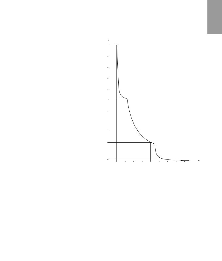
DRIVE THERMAL PROTECTION |
Thermal protection of the drive controller is achieved with a positive |
||||||||||||
|
temperature coefficient (PTC) resistor on the heatsink or power module. In |
||||||||||||
|
the event of an overcurrent, the drive controller trips to protect itself against |
||||||||||||
|
overloads. Typical tripping points are: |
|
|
|
|
|
|
||||||
|
• Motor current is 185% of nominal drive controller current for 2 seconds |
||||||||||||
|
• Motor current is 150% of nominal drive controller current for 60 seconds |
||||||||||||
|
Time |
|
|
|
|
|
|
|
|
|
|
|
|
|
(seconds) |
5000 |
|
|
|
|
|
|
|
|
|
|
|
|
|
|
|
|
|
|
|
|
|
|
|
|
|
|
|
3000 |
|
|
|
|
|
|
|
|
|
|
|
|
|
1000 |
|
|
|
|
|
|
|
|
|
|
|
|
|
200 |
|
|
|
|
|
|
|
|
|
|
|
|
|
160 |
|
|
|
|
|
|
|
|
|
|
|
|
|
100 |
|
|
|
|
|
|
|
|
|
|
|
|
|
60 |
|
|
|
|
|
|
|
|
|
|
|
|
|
2 |
|
|
|
|
|
|
|
|
|
|
|
|
|
0 |
|
|
|
|
|
|
|
|
|
|
|
|
|
1 |
1.1 |
1.2 |
1.3 |
1.4 |
1.5 |
1.6 |
1.7 |
1.8 |
1.9 |
|
|
|
|
|
|
|
|
|
|
|
|
Motor current/drive controller In |
|||
Ventilation |
The fan starts when the drive controller is powered up, but stops after |
||||||||||||
|
10 seconds if a run command is not received. The fan starts automatically |
||||||||||||
|
when the drive controller receives an operating direction and reference. It |
||||||||||||
|
stops a few seconds after motor speed is less than 0.2 Hz and injection |
||||||||||||
|
braking is completed. |
|
|
|
|
|
|
|
|
|
|||
ENGLISH
© 2004 Schneider Electric All Rights Reserved |
13 |
ENGLISH
Section 1: Introduction |
VVDED303042NAR6/04 |
Motor Thermal Protection |
06/2004 |
|
|
MOTOR THERMAL PROTECTION |
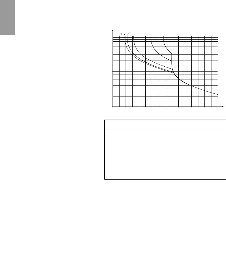
Motor thermal protection is achieved by continuous calculation of I2t. The |
|||
|
protection is available for self-cooled motors. |
|||
|
NOTE: The motor thermal state memory returns to zero when line power is |
|||
|
removed from the drive controller. |
|
||
|
Trip time in seconds |
|
|
|
|
1 Hz 3 Hz 5 Hz |
|
|
|
|
10,000 |
10 Hz |
20 Hz |
50 Hz |
|
|
|
|
|
1,000
1000.7 |
0.8 |
0.9 |
1 |
1.1 |
1.2 |
1.3 |
1.4 |
1.5 |
Motor current/ItH
CAUTION
INADEQUATE MOTOR THERMAL PROTECTION
The use of external overload protection is required under the following conditions:
•Starting from line power
•Running multiple motors
•Running motors rated at less than 0.2 times the nominal drive current
•Using motor switching
Failure to follow this instruction can result in equipment damage.
Refer to “Preliminary Recommendations” on pages 10–11 for more information about external overload protection.
14 |
© 2004 Schneider Electric All Rights Reserved |

VVDED303042NAR6/04 |
Section 2: Programming |
06/2004 |
|
|
|
SECTION 2: PROGRAMMING
ENGLISH
 DANGER
UNQUALIFIED USER
•This equipment must be installed, programmed, and serviced only by qualified personnel.
•The application of this product requires expertise in the design and programming of control systems. Only persons with such expertise should be allowed to program, install, alter, and apply this product.
•Qualified personnel performing diagnostics or troubleshooting that requires electrical conductors to be energized must comply with NFPA 70 E - Standard for Electrical Safety Requirements for Employee Workplaces and OSHA Standards - 29 CFR Part 1910 Subpart S Electrical.
Failure to follow these instructions will result in death or serious injury.
© 2004 Schneider Electric All Rights Reserved |
15 |

ENGLISH
Section 2: Programming |
VVDED303042NAR6/04 |
Drive Keypad Display |
06/2004 |
|
|
DRIVE KEYPAD DISPLAY
ATV31•••••• Controllers
Red LED
DC bus ON
Four 7-segment displays
Returns to the previous menu or  parameter, or increases the
displayed value
Advances to the next menu or parameter, or decreases the displayed value
Altivar 31
 RUN
RUN
CAN |
2 CANopen status LEDs |
|

 ERR
ERR
ESC 
 Exits a menu or parameter, or clears the displayed value to return to the previous stored value
ENT 
 Enters a menu or a parameter, or saves the displayed parameter or value
ATV31••••••A Controllers |
ATV31••••••A controllers have a reference potentiometer, a run button, and |
|
a stop/reset button. |
Red LED |
Altivar 31 |
DC bus ON |
|
|
RUN |
Four 7-segment displays |
CAN |
|
|
|
ERR |
Returns to the previous menu or parameter, |
|
or increases the displayed value |
ESC |
|
|
Advances to the next menu or parameter, or |
ENT |
decreases the displayed value |
|
RUN |
STOP |
|
Reference potentiometer: |
RESET |
||
|
|||
Active if parameter Fr1 in the CtLmenu is |
|
|
|
configured as AIP (see page 46) |
|
|
RUN button: Starts the motor in forward direction if parameter tCC in the I-O- menu is configured as LOC (see page 33)
 2 CANopen status LEDs
Exits a menu or a parameter,
or clears the displayed value to return to the previous stored value

 Enters a menu or a parameter, or saves the displayed parameter or value
STOP/RESET button
Resets faults
Stops the motor:
•If tCC (I-O- menu) is not configured as LOC, pressing the STOP/RESET key commands a freewheel stop.
•If tCC (I-O- menu) is configured as LOC, stopping is on a ramp, but if injection braking is in progress, a freewheel stop takes place.
16 |
© 2004 Schneider Electric All Rights Reserved |

VVDED303042NAR6/04 |
Section 2: Programming |
||
06/2004 |
|
Drive Keypad Display |
|
|
|
|
|
Key Functions |
• Press and hold down (longer than 2 seconds) the |
or |
keys to |
|
scroll through the data quickly. |
|
|
•Pressing  or
or  does not store the selection.
•To store the selection, press the ENT key.The display flashes when a value is stored.
|
A normal display with no fault present and no run command shows: |
|
|
• |
The value of one of the display parameters (see page 84). The default |
|
|
display is motor frequency, for example 43.0. In current limiting mode, |
|
|
the display flashes. |
|
• |
Init: Initialization sequence |
|
• |
rdY: Drive ready |
|
• |
dcb: DC injection braking in progress |
|
• |
nSt: Freewheel stop |
|
• |
FSt: Fast stop |
|
• |
tUn: Auto-tuning in progress |
|
If a fault is present, the display flashes. |
|
nSt: Freewheel Stop |
If the display shows the code nSt, one of the following conditions is |
|
|
indicated: |
|
|
1. |
With the factory configuration, when the drive controller is powered up |
|
|
after a manual fault reset or stop command, the forward, reverse, and |
|
|
DC injection stop commands must be reset for the drive controller to |
|
|
start. If they are not reset, the drive controller will display nSt and will not |
|
|
start. If automatic restart is configured, the reset is not necessary. |
|
2. |
If the reference channel or the control channel is assigned to Modbus or |
|
|
CANopen (see page 36), the drive controller will display nSt on power up |
|
|
and remain stopped until the communication bus sends a command. |
|
3. |
If a forward or reverse run command is present when the drive controller |
|
|
is powered up and the drive controller is set for 3-wire control or for |
2-wire control with “trn” transition (see page 33) the drive controller will display nSt and will not run until the run command is cycled and a valid speed reference is given.
ENGLISH
© 2004 Schneider Electric All Rights Reserved |
17 |
ENGLISH
Section 2: Programming |
VVDED303042NAR6/04 |
Remote Keypad Display |
06/2004 |
|
|
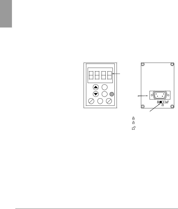
REMOTE KEYPAD DISPLAY |
The optional remote keypad display is a local control unit that can be wall- |
|
mounted on the door of an enclosure. It has a cable with connectors for |
|
connection to the drive serial link (refer to the manual supplied with the |
|
display). The remote keypad display has the same display and |
|
programming buttons as the drive controller, with the addition of a switch to |
|
lock access to the menu and three buttons for commanding the drive |
|
controller: |
|
• FWD/REV commands the direction of rotation. |
|
• RUN commands the motor to run. |
|
• STOP/RESET commands the motor to stop or resets a fault. Pressing |
|
the STOP/RESET button once stops the motor; pressing it a second |
|
time stops DC injection braking if it is configured. |
|
In order for the remote keypad display to be active, the tbr parameter in the |
|
COMmenu must remain at the factory setting, 19.2 (19,200 bps, see |
|
page 82). |
|
|
|
4-character |
|
|
|
display |
|
|
ESC |
|
|
|
ENT |
Connector |
|
|
|
|
FWD |
RUN |
|
STOP |
REV |
|
RESET |
Access locking switch:
• Positions:
• Position:
settings and display are accessible (SEtand SUPmenus)
all menus can be accessed
|
NOTE: Password protection has priority over the access locking switch. See |
|
page 86. |
|
Placing the access locking switch in the locked position also prevents the |
|
drive settings from being accessed via the drive controller keypad. When |
|
the remote keypad display is disconnected, if the access locking |
|
switch is in the locked position, the drive controller keypad also |
|
remains locked. |
Saving and Loading Configurations |
Up to four complete configurations can be stored in the remote keypad |
|
display and transferred to other drive controllers of the same rating. Four |
|
different operations for the same device can also be stored on the terminal. |
|
See the SCS and FCS parameters in the drC-, I-O-, CtL-, or FUnmenus. |
|
See pages 32, 35, 49, and 77. |
18 |
© 2004 Schneider Electric All Rights Reserved |
VVDED303042NAR6/04 |
Section 2: Programming |
06/2004 |
Accessing the Menus |
|
|
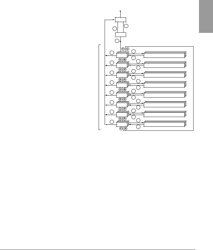
ACCESSING THE MENUS
Menus
Power-up
XXX Displays drive controller status (variable, see page 17)
 ESC
ESC
ENT 
Motor frequency (the factory setting is only visible bFr the first time the drive is powered up. See page 20.)
ENT |
|
|
ESC |
ENT |
|
Settings (page 25) |
||
SEt- |
||
|
ESC |
|
ESC |
ENT |
|
Drive control (page 29) |
||
drC- |
||
|
ESC |
|
ESC |
ENT |
|
I/O (page 33) |
||
I-O- |
||
|
||
|
ESC |
|
ESC |
ENT |
|
Control (page 36) |
||
CtL- |
||
|
ESC |
|
ESC |
ENT |
|
Functions (page 50) |
||
FUn- |
||
|
ESC |
|
ESC |
ENT |
|
Faults (page 78) |
||
FLt- |
||
|
ESC |
|
ESC |
ENT |
|
Communication (page 82) |
||
CON- |
||
|
ESC |
|
ESC |
ENT |
|
Monitoring (page 84) |
||
SUP- |
||
|
ESC |
For added convenience, some parameters can be accessed in more than one menu. For example, return to factory settings (FCS) and saving the configuration (SCS) are available in multiple menus.
NOTE: Throughout this guide, a dash appears after menu codes to differentiate them from parameter codes. For example, SEtis a menu, but ACC is a parameter.
ENGLISH
© 2004 Schneider Electric All Rights Reserved |
19 |
ENGLISH
Section 2: Programming |
VVDED303042NAR6/04 |
Accessing the Parameters |
06/2004 |
|
|
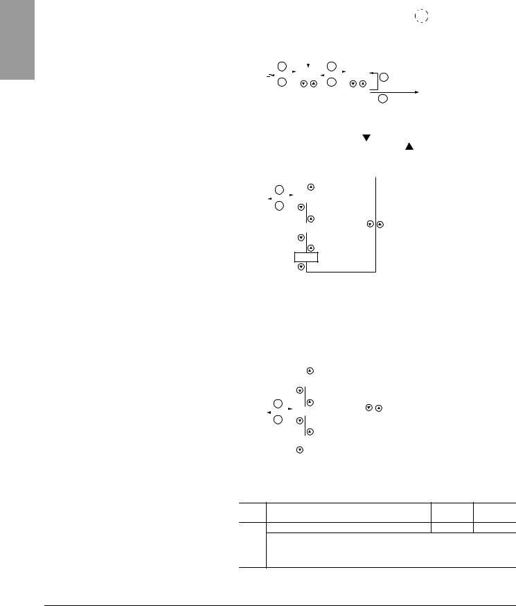
ACCESSING THE PARAMETERS |
The following figure illustrates how to access parameters and assign their |
|||||||||||||||||||||||||
|
values. To store the parameter value, press the ENT key. The display |
|||||||||||||||||||||||||
|
flashes when a value is stored. |
|
|
|
|
|
|
|||||||||||||||||||
|
|
|
Menu |
|
Parameter |
|
|
Value Assignment |
|
|
|
|
||||||||||||||
|
|
|
|
|
|
|
|
|
|
|
|
|
|
|
|
|
|
|
|
|
|
|
|
|
|
The display |
|
|
|
|
|
|
|
|
|
|
|
|
|
|
|
|
|
|
|
|
|
|
|
|
|
|
|
|
|
|
|
|
|
|
ENT |
|
|
|
|
|
|
|
|
|
ENT |
|
|
|
|
|
||||
|
|
|
SEt- |
|
|
|
|
|
ACC |
|
|
|
|
15.0 |
|
ESC |
|
|
|
flashes when a |
||||||
|
|
|
|
|
|
|
|
|
|
|
|
|
|
|
|
|||||||||||
|
|
|
|
|
|
|
|
|
|
|
|
|
|
|
|
|||||||||||
|
|
|
|
|
|
|
ESC |
|
|
|
|
|
|
|
|
|
ESC |
|
|
|
|
|
|
value is stored. |
||
|
|
|
|
|
|
|
|
|
|
|
dEC |
|
|
26.0 |
|
ENT |
|
26.0 |
|
|
||||||
|
|
|
|
|
|
|
|
|
|
|
||||||||||||||||
|
|
|
|
|
|
|
|
|
|
|
|
|
|
|
|
|
|
|
|
|
|
|
|
|
|
|
|
|
|
|
|
|
|
|
Next Parameter |
|
|
|
|
||||||||||||||
|
|
|
|
|
|
|
|
|
|
|
|
|
|
|||||||||||||
|
All of the menus are drop-down type menus. Once you have reached the |
|||||||||||||||||||||||||
|
last parameter in a list, press the |
key to return to the first parameter. |
||||||||||||||||||||||||
|
From the first parameter in the list, press the |
key to jump to the last |
||||||||||||||||||||||||
|
parameter. |
|
|
|
|
|
|
|
|
|
|
|
|
|
|
|
|
|
|
|
||||||
|
|
|
|
|
|
|
ENT |
|
|
|
|
|
|
|
|
|
|
|
|
|
|
|
|
|
|
|
|
|
|
|
|
|
|
|
|
|
|
|
|
|
1st |
|
|
|
|
|
|
||||||
|
|
Menu |
|
|
|
|
|
|
|
|
|
|
|
|
|
|
|
|
|
|
|
|
||||
|
|
|
|
|
|
|
ESC |
|
|
|
|
|
|
|
|
|
|
|
|
|
|
|
|
|
|
|
|
|
|
|
|
|
|
|
|
|
|
|
|
|
|
|
|
|
|
|
|
|
|
|
|
|
|
|
|
|
|
|
|
|
|
|
|
|
|
|
|
|
nth |
|
|
|
|
|
|
|||||
|
|
|
|
|
|
|
|
|
|
|
|
|
|
|
|
|
|
|
|
|
||||||
|
|
|
|
|
|
|
|
|
|
|
|
|
|
|
|
|
|
|
|
|
|
|
|
|
|
|
last
If you have modified a parameter in a menu and you return to that menu without accessing another menu in the meantime, you will be taken directly to the parameter you last modified. See the illustration below. If you have accessed another menu or have restarted the drive controller since the modification, you will be taken to the first parameter in the menu. See the illustration above.
|
|
|
|
|
|
|
|
1st |
|
|
|
|
|
|
|
|
|
|
|
|
|
|
|
|
|
|
|
|
|
|
|
|
|
|
|
|
|
|
|
ENT |
|
|
|
||||
|
|
Menu |
|
|
|
|
|
nth |
|
|
|
|
|
|
|
|
|
|
|
|
|
||
|
|
|
|
|
|
|
|
|
|
||
|
|
|
|
ESC |
|
|
|
||||
bFr Parameter |
|
|
|
|
|
|
|
last |
|
|
|
|
|
|
|
|
|
|
|
|
|
||
|
|
|
|
|
|
|
|
|
|
|
|
Motor frequency, bFr, can only be modified when the drive controller is |
|||||||||||
|
stopped and not receiving a run command. |
|
|
||||||||
|
Code |
Description |
Adjustment Factory |
||||||||
|
range |
setting |
|||||||||
|
|
|
|
|
|
|
|
|
|
||
|
|
bFr |
Motor frequency |
50 or 60 Hz |
50 Hz |
||||||
|
|
|
This is the first parameter displayed when the drive controller is first powered up. |
||||||||
|
|
|
bFr can be modified at any time in the drCmenu. |
|
|
||||||
|
|
|
Modifying this parameter also modifies the values of the following parameters: HSP |
||||||||
|
|
|
(page 26), Ftd (page 29), FrS (page 30), and tFr (page 32). |
|
|||||||
20 |
© 2004 Schneider Electric All Rights Reserved |
VVDED303042NAR6/04 |
|
|
|
|
|
|
|
|
|
Section 2: Programming |
||||||||
06/2004 |
|
|
|
|
|
|
|
|
|
Function Compatibility |
||||||||
|
|
|
|
|
|
|
|
|
|
|
|
|
|
|
|
|||
FUNCTION COMPATIBILITY |
Automatic restart, catch on the fly, and reverse direction are only available |
|||||||||||||||||
|
as described below: |
|
|
|
|
|
|
|
|
|
|
|
|
|
|
|
|
|
|
• Automatic restart is only available in 2-wire control (tCC = 2C and |
|
||||||||||||||||
|
tCt = LEL or PFO, see page 33). |
|
|
|
|
|
|
|
|
|
|
|
|
|||||
|
• Catch on the fly is only available in 2-wire control (tCC = 2C and |
|
||||||||||||||||
|
tCt = LEL or PFO, see page 33). It is deactivated if automatic DC |
|
||||||||||||||||
|
injection braking is configured as DC (AdC = Ct, see page 55). |
|
|
|
||||||||||||||
|
• Reverse direction is only available on ATV31••••••A controllers if local |
|||||||||||||||||
|
control is active (tCC = LOC, see page 33). |
|
|
|
|
|
|
|
|
|
||||||||
|
The choice of application functions is limited by the number of I/O available |
|||||||||||||||||
|
and by the fact that some functions are incompatible with one another as |
|||||||||||||||||
|
illustrated in the figure below. Functions which are not listed in the figure are |
|||||||||||||||||
|
fully compatible. If there is an incompatibility between functions, the first |
|
||||||||||||||||
|
function configured will prevent the others from being configured. |
|
|
|
||||||||||||||
|
|
|
|
|
|
|
|
|
|
|
|
|
|
|
|
|
|
|
|
|
|
|
|
|
switches |
|
|
|
|
|
|
|
|
|
|
|
|
|
|
|
Summing inputs |
1 |
Management of limit |
|
Preset speeds |
PI regulator |
Jog operation |
Brake sequence |
DC injection stop |
|
|
|
Freewheel stop |
|||
|
|
|
|
+/- Speed |
|
|
Fast stop |
|
||||||||||
|
|
|
|
|
|
|
|
|
|
|
|
|
|
|
|
|
|
|
|
Summing inputs |
|
|
|
|
|
|
|
|
|
|
|
|
|
|
|
|
|
|
|
|
|
|
|
|
|
|
|
|
|
|
|
|
|
|
|
|
|
+/- Speed 1 |
|
|
|
|
|
|
|
|
|
|
|
|
|
|
|
|
|
|
Management of limit |
|
|
|
|
|
|
|
|
|
|
|
|
|
|
|
|
|
|
switches |
|
|
|
|
|
|
|
|
|
|
|
|
|
|
|
|
|
|
Preset speeds |
|
|
|
|
|
|
|
|
|
|
|
|
|
|
|
|
|
|
|
|
|
|
|
|
|
|
|
|
|
|
|
|
|
|
|
|
|
PI regulator |
|
|
|
|
|
|
|
|
|
|
|
|
|
|
|
|
|
|
|
|
|
|
|
|
|
|
|
|
|
|
|
|
|
|
|
|
|
Jog operation |
|
|
|
|
|
|
|
|
|
|
|
|
|
|
|
|
|
|
Brake sequence |
|
|
|
|
|
|
|
|
|
|
|
|
|
|
|
|
|
|
|
|
|
|
|
|
|
|
|
|
|
|
|
|
|
|
|
|
|
DC injection stop |
|
|
|
|
|
|
|
|
|
|
|
|
|
|
|
|
|
|
|
|
|
|
|
|
|
|
|
|
|
|
|
|
|
|
|
|
|
Fast stop |
|
|
|
|
|
|
|
|
|
|
|
|
|
|
|
|
|
|
|
|
|
|
|
|
|
|
|
|
|
|
|
|
|
|
|
|
|
Freewheel stop |
|
|
|
|
|
|
|
|
|
|
|
|
|
|
|
||
|
1 Excluding a special application with reference channel Fr2 (see pages 41 and 43). |
|
|
|
||||||||||||||
|
|
Incompatible functions |
|
|
|
Compatible functions |
|
|
|
Not applicable |
||||||||
|
|
|
|
|
|
|
|
|||||||||||
|
|
|
|
|
|
|
|
|
|
|
|
|
|
|
|
|
|
|
Functions which cannot be active at the same time. The arrow points to the function that has priority.
Stop functions have priority over run commands. Speed references via logic command have priority over analog references.
ENGLISH
© 2004 Schneider Electric All Rights Reserved |
21 |

ENGLISH
Section 2: Programming |
VVDED303042NAR6/04 |
Logic and Analog Input Application Functions |
06/2004 |
|
|
LOGIC AND ANALOG INPUT APPLICATION FUNCTIONS
Table 2: |
Logic Inputs |
Tables 2–5 list the functions that can be assigned to the logic and analog inputs and their factory assignments. A single input can activate several functions at the same time. For example, reverse and second ramp can be assigned to one input. When more than one function is assigned to an input, ensure that the functions are compatible. Use the LIAand AIA- sub-menus of the SUPmenu (see page 86) to display the functions assigned to the inputs and to check their compatibility.
Function |
Code |
See Page: |
Factory Setting |
||
ATV31•••••• |
|
ATV31••••••A |
|||
|
|||||
|
|
|
|
||
|
|
|
|
|
|
Not assigned |
— |
— |
LI5–LI6 |
|
LI1–LI2 |
|
LI5–LI6 |
||||
|
|
|
|
|
|
|
|
|
|
|
|
Forward |
— |
— |
LI1 |
|
|
|
|
|
|
|
|
2 preset speeds |
PS2 |
58 |
LI3 |
|
LI3 |
|
|
|
|
|
|
4 preset speeds |
PS4 |
58 |
LI4 |
|
LI4 |
|
|
|
|
|
|
8 preset speeds |
PS8 |
58 |
— |
|
— |
|
|
|
|
|
|
16 preset speeds |
PS16 |
59 |
— |
|
— |
|
|
|
|
|
|
2 preset PI references |
Pr2 |
68 |
— |
|
— |
|
|
|
|
|
|
4 preset PI references |
Pr4 |
68 |
— |
|
— |
|
|
|
|
|
|
+ speed |
USP |
63 |
— |
|
— |
|
|
|
|
|
|
- speed |
dSP |
63 |
— |
|
— |
|
|
|
|
|
|
Jog operation |
JOG |
60 |
— |
|
— |
|
|
|
|
|
|
Ramp switching |
rPS |
52 |
— |
|
— |
|
|
|
|
|
|
Switching for 2nd current limit |
LC2 |
73 |
— |
|
— |
Fast stop via logic input |
FSt |
53 |
— |
|
— |
|
|
|
|
|
|
DC injection via logic input |
dCI |
53 |
— |
|
— |
|
|
|
|
|
|
Freewheel stop via logic input |
nSt |
54 |
— |
|
— |
|
|
|
|
|
|
Reverse |
rrS |
33 |
LI2 |
|
— |
|
|
|
|
|
|
External fault |
EtF |
80 |
— |
|
— |
|
|
|
|
|
|
RESET (fault reset) |
rSF |
79 |
— |
|
— |
|
|
|
|
|
|
Forced local mode |
FLO |
82 |
— |
|
— |
|
|
|
|
|
|
Reference switching |
rFC |
47 |
— |
|
— |
|
|
|
|
|
|
Control channel switching |
CCS |
48 |
— |
|
— |
|
|
|
|
|
|
Motor switching |
CHP |
74 |
— |
|
— |
|
|
|
|
|
|
Limiting of forward motion (limit switch) |
LAF |
76 |
— |
|
— |
|
|
|
|
|
|
Limiting of reverse motion (limit switch) |
LAr |
76 |
— |
|
— |
|
|
|
|
|
|
Fault inhibit |
InH |
81 |
— |
|
— |
|
|
|
|
|
|
Table 3: |
Analog Inputs |
|
|
|
|
|
|
|
|
|
|
|
|
Function |
|
Code |
See Page: |
Factory Setting |
||
|
ATV31•••••• |
|
ATV31••••••A |
|||
|
|
|||||
|
|
|
|
|
||
|
|
|
|
|
|
|
Not assigned |
|
— |
— |
AI3 |
|
AI1 - AI3 |
|
|
|
|
|
|
|
Reference 1 |
|
Fr1 |
46 |
AI1 |
|
AIP |
|
|
(potentiometer) |
||||
|
|
|
|
|
|
|
|
|
|
|
|
|
|
Reference 2 |
|
Fr2 |
46 |
|
|
— |
|
|
|
|
|
|
|
Summing input 2 |
SA2 |
56 |
AI2 |
|
AI2 |
|
|
|
|
|
|
|
|
Summing input 3 |
SA3 |
56 |
— |
|
— |
|
|
|
|
|
|
|
|
PI regulator feedback |
PIF |
68 |
— |
|
— |
|
|
|
|
|
|
|
|
22 |
© 2004 Schneider Electric All Rights Reserved |

VVDED303042NAR6/04 |
Section 2: Programming |
06/2004 |
Logic and Analog Input Application Functions |
|
|
Table 4: Analog and Logic Outputs
Function |
|
Code |
See Page: |
Factory Setting |
|
ENGLISH |
|
|
|||||
|
|
|
|
|
|
|
Not assigned |
|
— |
— |
AOC/AOV |
|
|
|
|
|
|
|
|
|
Motor current |
|
OCr |
34 |
— |
|
|
|
|
|
|
|
|
|
Motor frequency |
|
rFr |
34 |
— |
|
|
|
|
|
|
|
|
|
Motor torque |
|
OLO |
34 |
— |
|
|
|
|
|
|
|
|
|
Power supplied by the drive controller |
OPr |
34 |
— |
|
||
|
||||||
|
|
|
|
|
|
|
Drive fault (logic data) |
FLt |
34 |
— |
|
||
|
|
|
|
|
|
|
Drive running (logic data) |
rUn |
34 |
— |
|
||
|
|
|
|
|
|
|
Frequency threshold reached (logic data) |
FtA |
34 |
— |
|
||
|
|
|
|
|
|
|
High speed (HSP) reached (logic data) |
FLA |
34 |
— |
|
||
|
|
|
|
|
|
|
Current threshold reached (logic data) |
CtA |
34 |
— |
|
||
|
|
|
|
|
|
|
Frequency reference reached (logic data) |
SrA |
34 |
— |
|
||
|
|
|
|
|
|
|
Motor thermal threshold reached (logic data) |
tSA |
34 |
— |
|
||
|
|
|
|
|
|
|
Brake sequence (logic data) |
bLC |
34 |
— |
|
||
|
|
|
|
|
|
|
Table 5: |
Relays |
|
|
|
|
|
|
|
|
|
|
|
|
Function |
|
Code |
See Page: |
Factory Setting |
|
|
|
|
|
|
|
|
|
Not assigned |
|
— |
— |
R2 |
|
|
|
|
|
|
|
|
|
Drive fault |
|
FLt |
34 |
R1 |
|
|
|
|
|
|
|
|
|
Drive running |
|
rUn |
34 |
— |
|
|
|
|
|
|
|
|
|
Frequency threshold reached |
FtA |
34 |
— |
|
||
|
|
|
|
|
|
|
High speed (HSP) reached |
FLA |
34 |
— |
|
||
|
|
|
|
|
|
|
Current threshold reached |
CtA |
34 |
— |
|
||
|
|
|
|
|
|
|
Frequency reference reached |
SrA |
34 |
— |
|
||
|
|
|
|
|
|
|
Motor thermal threshold reached |
tSA |
34 |
— |
|
||
|
|
|
|
|
|
|
Brake sequence |
|
bLC |
34 |
— |
|
|
|
|
|
|
|
|
|
© 2004 Schneider Electric All Rights Reserved |
23 |

Section 2: Programming |
VVDED303042NAR6/04 |
Logic and Analog Input Application Functions |
06/2004 |
|
|
ENGLISH
24 |
© 2004 Schneider Electric All Rights Reserved |

VVDED303042NAR6/04 |
Section 3: Menus |
06/2004 |
Settings Menu SEt- |
|
|
SECTION 3: MENUS
 DANGER
UNINTENDED EQUIPMENT OPERATION
Ensure that changes to the operating settings do not present any danger, especially when making adjustments while the drive controller is running the motor.
Failure to follow these instructions will result in death or serious injury.
CAUTION
MOTOR OVERHEATING
•This drive controller does not provide direct thermal protection for the motor.
•Use of a thermal sensor in the motor may be required for protection at all speeds or loading conditions.
•Consult the motor manufacturer for the thermal capability of the motor when operated over the desired speed range.
Failure to follow these instructions can result in equipment damage.
SETTINGS MENU SEt-
ENT |
ENT |
SEt- |
LFr |
ESC |
ESC |
ESC |
ENT |
|
|
|
rPI |
|
ESC |
ESC |
ENT |
|
|
|
ACC |
|
ESC |
ESC |
ENT |
|
|
|
SdS |
|
ESC |
Speed reference from the remote keypad
Scale factor for SPd1–SPd3 parameters
The parameters in the SEtmenu can be modified with the drive controller running or stopped. However, we recommend making modifications to the settings with the drive controller stopped.
ENGLISH
© 2004 Schneider Electric All Rights Reserved |
25 |

ENGLISH
Section 3: Menus |
VVDED303042NAR6/04 |
Settings Menu SEt- |
06/2004 |
|
|
SEt-

Code |
Description |
|
Adjustment Range |
Factory Setting |
|
|
|
|
|
|
|
|
Speed reference from the remote keypad. |
|
0 to HSP |
|
|
|
|
|
|
||
LFr1 |
This parameter appears if LCC = YES (page 48) or if Fr1/Fr2 = LCC (page 46), and if the remote keypad is online. In this case, |
||||
|
LFr can also be accessed via the drive controller keypad. |
|
|
|
|
|
LFr is reset to 0 when the drive controller is powered down. |
|
|
|
|
rPI1 |
Internal PI regulator reference |
See page 64. |
0.0 to 100% |
0 |
|
ACC |
Acceleration ramp time |
|
0.1 to 999.9 s |
3 s |
|
|
Defined as the time it takes for the motor to go from 0 Hz to FrS (nominal frequency, see page 30). |
|
|||
|
|
|
|
|
|
AC2 |
2nd acceleration ramp time |
See page 52. |
0.1 to 999.9 s |
5 s |
|
dE2 |
2nd deceleration ramp time |
See page 52. |
0.1 to 999.9 s |
5 s |
|
|
Deceleration ramp time |
|
0.1 to 999.9 s |
3 s |
|
|
|
|
|
||
dEC |
Defined as the time it takes for the motor to go from FrS (nominal frequency, see page 30) to 0 Hz. |
|
|||
|
Ensure that dEC is not set too low for the load. |
|
|
|
|
|
|
|
|
|
|
tA1 |
Start of custom acceleration ramp, rounded as a percentage |
See page 51. |
0 to 100 |
10% |
|
of total ramp time (ACC or AC2) |
|||||
|
|
|
|
||
tA2 |
End of custom acceleration ramp, rounded as a percentage of |
See page 51. |
0 to (100-tA1) |
10% |
|
|
total ramp time (ACC or AC2) |
|
|
|
|
tA3 |
Start of custom deceleration ramp, rounded as a percentage |
See page 51. |
0 to 100 |
10% |
|
of total ramp time (dEC or dE2) |
|||||
|
|
|
|
||
tA4 |
End of custom deceleration ramp, rounded as a percentage of |
See page 51. |
0 to (100-tA3) |
10% |
|
|
total ramp time (dEC or dE2) |
|
|
|
|
LSP |
Low speed |
|
0 to HSP |
0 Hz |
|
|
|
|
|
||
Minimum reference |
|
|
|
||
|
|
|
|
||
|
|
|
|
|
|
HSP |
High speed |
|
LSP to tFr |
bFr |
|
|
|
|
|
||
Maximum reference. Ensure that this setting is suitable for the motor and the application. |
|
||||
|
|
||||
|
|
|
|
|
|
|
Current used for motor thermal protection. |
|
0.2 to 1.5 In2 |
Varies with drive |
|
ItH |
|
|
|
controller rating |
|
Set ItH to the full-load amperes (FLA) indicated on the motor nameplate. |
|
|
|||
|
|
|
|||
|
Refer to OLL on page 80 if you wish to suppress motor thermal protection. |
|
|
||
|
|
|
|
|
|
1Also accessible in the SUPmenu.
2In is the nominal drive controller current indicated on the drive controller nameplate.
These parameters appear regardless of how the other menus have been configured.
They only appear in the Settings menu.
These parameters only appear if the corresponding function has been selected in another menu. To facilitate programming, they can also be accessed and adjusted from the menu where the corresponding function is found. A detailed description of these functions can be found on the indicated pages.
26 |
© 2004 Schneider Electric All Rights Reserved |
VVDED303042NAR6/04 |
Section 3: Menus |
06/2004 |
Settings Menu SEt- |
|
|
SEt-


Code |
Description |
|
Adjustment Range |
Factory Setting |
|
|
|
|
|
|
|
|
|
IR compensation or voltage boost |
|
0 to 100% |
20 |
|
|
|
|
|
|
|
|
If UFt (page 31) = n or nLd, UFr is IR compensation. |
|
|
|
|
|
If UFt = L or P, UFr is voltage boost. |
|
|
|
UFr |
|
|
|
|
|
Used to optimize torque at very low speed. Increase UFr if the torque is insufficient.
To avoid operating instability, ensure that the value of UFr is not too high for a warm motor.
NOTE: Modifying UFt (page 31) will cause UFr to return to the factory setting (20%).
|
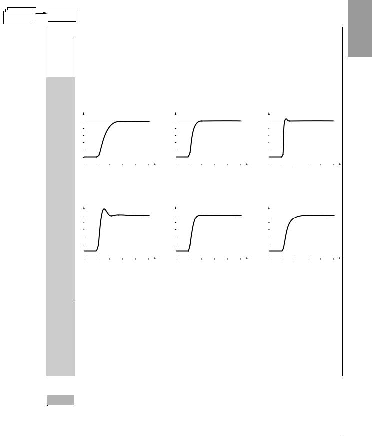
Frequency loop gain |
1 to 100% |
20 |
|
|
|
|
This parameter can only be accessed if UFt (page 31) = n or nLd.
FLG adjusts the speed ramp based on the inertia of the driven load.
If the value is too low, the response time is longer. If the value is too high, operating instability can result.
|
Hz |
|
FLG low |
Hz |
|
FLG correct |
|
|
Hz |
|
|
FLG high |
|||||
|
|
|
|
|
|
|
|||||||||||
50 |
|
|
|
|
50 |
|
|
|
50 |
|
|
|
|
|
|||
FLG |
|
|
|
40 |
|
|
|
40 |
|
|
|
|
|
||||
40 |
|
|
|
|
|
|
|
|
|
|
|
|
|||||
30 |
|
|
In this case, |
30 |
|
|
|
30 |
|
|
In this case, |
||||||
|
|
increase FLG |
|
|
|
|
|
reduce FLG |
|||||||||
20 |
|
|
20 |
|
|
|
20 |
|
|
||||||||
|
|
|
|
|
|
|
|
|
|
|
|
||||||
10 |
|
|
|
|
10 |
|
|
|
10 |
|
|
|
|
|
|||
0 |
|
|
|
|
0 |
|
|
|
0 |
|
|
|
|
|
|||
-10 |
|
|
|
|
-10 |
|
|
|
|
-10 |
|
|
|
|
|
||
0 |
0.1 0.2 0.3 0.4 0.5 t |
0 |
0.1 0.2 0.3 0.4 |
0.5 t |
0 |
0.1 0.2 0.3 0.4 0.5 t |
|||||||||||
|
|
|
|
|
|
|
|
|
|
|
|
|
|
|
|
|
|
|
Frequency loop stability |
|
|
|
|
|
1 to 100% |
|
|
|
20 |
|
|||||
|
|
|
|
|
|
|
|
|
|
|
|
|
|
|
|
|
|
This parameter can only be accessed if UFt (page 31) = n or nLd.
After a period of acceleration or deceleration, StA adapts the return to a steady state to the dynamics of the machine.
If the value is too low, overspeed or operating instability can result. If the value is too high, the response time is longer.
|
|
Hz |
|
|
StA low |
|
|
|
Hz |
|
|
StA correct |
|
|
|
Hz |
|
|
|
StA high |
|
|
|
||||||
|
|
|
|
|
|
|
|
|
|
|
|
|
|
|
|
|
|||||||||||||
StA |
50 |
|
|
|
|
|
|
|
|
50 |
|
|
|
|
|
|
|
50 |
|
|
|
|
|
|
|
|
|
||
40 |
|
|
|
|
|
|
|
|
40 |
|
|
|
|
|
|
|
40 |
|
|
|
|
|
|
|
|
|
|||
|
|
|
|
|
In this case, |
|
|
|
|
|
|
|
|
|
|
|
|
|
In this case, reduce |
||||||||||
|
|
30 |
|
|
|
|
|
|
30 |
|
|
|
|
|
|
|
30 |
|
|
|
|||||||||
|
|
|
|
|
increase StA |
|
|
|
|
|
|
|
|
|
|
|
|
|
StA |
|
|
|
|
||||||
|
|
|
|
|
|
|
|
|
|
|
|
|
|
|
|
|
|
|
|
|
|
|
|
|
|
||||
|
|
20 |
|
|
|
|
|
|
|
|
20 |
|
|
|
|
|
|
|
20 |
|
|
|
|
|
|
|
|
|
|
|
|
10 |
|
|
|
|
|
|
|
|
10 |
|
|
|
|
|
|
|
10 |
|
|
|
|
|
|
|
|
|
|
|
|
0 |
|
|
|
|
|
|
|
|
0 |
|
|
|
|
|
|
|
0 |
|
|
|
|
|
|
|
|
|
|
|
|
-10 |
|
|
|
|
|
|
|
|
-10 |
|
|
|
|
|
|
|
|
-10 |
|
|
|
|
|
|
|
|
|
|
|
0 |
0.1 |
0.2 |
0.3 |
0.4 |
0.5 t |
0 |
0.1 |
0.2 |
0.3 |
0.4 |
0.5 |
t |
0 |
0.1 |
0.2 |
0.3 |
0.4 |
0.5 t |
|||||||||
|
|
|
|
|
|
|
|
|
|
|
|
|
|
|
|
|
|
|
|
|
|
|
|
|
|
|
|
|
|
|
|
Slip compensation |
|
|
|
|
|
|
|
|
|
|
|
|
0 to 150% |
|
|
|
|
100 |
|
|
|
|
|||||
|
|
|
|
|
|
|
|
|
|
|
|
|
|
|
|
|
|
|
|
|
|
|
|||||||
|
|
This parameter can only be accessed if UFt (page 31) = n or nLd. |
|
|
|
|
|
|
|
|
|
|
|
|
|
||||||||||||||
SLP |
SLP adjusts slip compensation for fine tuning of speed regulation. |
|
|
|
|
|
|
|
|
|
|
|
|
|
|||||||||||||||
|
|
|
|
|
|
|
|
|
|
|
|
|
|
|
|||||||||||||||
|
|
If the slip setting < actual slip, the motor is not rotating at the correct speed in steady state. |
|
|
|
|
|
|
|
|
|
||||||||||||||||||
|
|
If the slip setting > actual slip, the motor is overcompensated and the speed is unstable. |
|
|
|
|
|
|
|
|
|
||||||||||||||||||
|
|
|
|
|
|
|
|
|
|
|
|
|
|
|
|
|
|
|
|
|
|
|
|
|
|
|
|
|
|
|
|
|
|
|
|
|
|
|
|
|
|
|
|
|
|
|
|
|
0 to In (In is the |
|
|
|
|
|
|
|
|||
|
|
Level of DC injection braking current activated via a logic input |
|
|
|
nominal drive |
|
|
|
|
|
|
|
||||||||||||||||
IdC |
See page 53. |
|
controller current |
|
0.7 In |
|
|
|
|||||||||||||||||||||
or selected as a stop mode.1 |
|
|
|
|
|
|
|
|
|
|
|
|
|||||||||||||||||
|
|
|
|
|
|
|
|
|
|
|
|
|
|
|
|
|
|
|
indicated on the |
|
|
|
|
|
|
|
|||
|
|
|
|
|
|
|
|
|
|
|
|
|
|
|
|
|
|
|
nameplate). |
|
|
|
|
|
|
|
|||
|
|
|
|
|
|
|
|
|
|
|
|
|
|
|
|
|
|
|
|
|
|
||||||||
tdC |
Total DC injection braking time selected as a stop mode.1 |
|
See page 53. |
|
0.1 to 30 s |
|
|
|
|
0.5 s |
|
|
|
||||||||||||||||
|
|
|
|
|
|
|
|
|
|
|
|
|
|
|
|
|
|
|
|
|
|
|
|
||||||
tdC1 |
Automatic DC injection time |
|
|
|
|
|
|
|
See page 55. |
|
0.1 to 30 s |
|
|
|
|
0.5 s |
|
|
|
||||||||||
|
|
|
|
|
|
|
|
|
|
|
|
|
|
|
|
|
|
|
|
|
|
|
|||||||
SdC1 |
Level of automatic DC injection current |
|
|
|
|
|
See page 55. |
|
0 to 1.2 In |
|
|
|
|
0.7 In |
|
|
|
||||||||||||
|
|
|
|
|
|
|
|
|
|
|
|
|
|
|
|
|
|
|
|
|
|
|
|
|
|||||
tdC2 |
2nd automatic DC injection time |
|
|
|
|
|
|
|
See page 55. |
|
0 to 30 s |
|
|
|
|
0 s |
|
|
|
|
|||||||||
|
|
|
|
|
|
|
|
|
|
|
|
|
|
|
|
|
|
|
|
|
|
|
|
||||||
SdC2 |
2nd level of DC injection current |
|
|
|
|
|
|
|
See page 55. |
|
0 to 1.2 In |
|
|
|
|
0.5 In |
|
|
|
||||||||||
1 These settings are not related to the Automatic DC Injection function.
These parameters only appear if the corresponding function has been selected in another menu. To facilitate programming, they can also be accessed and adjusted from the menu where the corresponding function is found. A detailed description of these functions can be found on the indicated pages.
ENGLISH
© 2004 Schneider Electric All Rights Reserved |
27 |

ENGLISH
Section 3: Menus |
VVDED303042NAR6/04 |
Settings Menu SEt- |
06/2004 |
|
|
SEt-

Code |
Description |
|
Adjustment Range |
Factory Setting |
|
|
|
|
|
|
|
|
Skip frequency |
|
0 to 500 |
0 Hz |
|
|
|
|
|
||
JPF |
JPF prevents prolonged operation at a frequency range of ± 1 Hz around JPF. This function avoids a critical speed which leads |
||||
|
to resonance. Setting the function to 0 renders it inactive. |
|
|
|
|
|
|
|
|
|
|
|
2nd skip frequency |
|
0 to 500 |
0 Hz |
|
JF2 |
JF2 prevents prolonged operation at a frequency range of ± 1 Hz around JF2. This function avoids a critical speed which leads to |
||||
|
resonance. Setting the function to 0 renders it inactive. |
|
|
|
|
|
|
|
|
|
|
JGF |
Jog operating frequency |
See page 60. |
0 to 10 Hz |
10 |
Hz |
|
|
|
|
|
|
rPG |
PI regulator proportional gain |
See page 68. |
0.01 to 100 |
1 |
|
|
|
|
|
|
|
rIG |
PI regulator integral gain |
See page 68. |
0.01 to 100/s |
1/s |
|
|
|
|
|
|
|
FbS |
PI feedback multiplication coefficient |
See page 68. |
0.1 to 100 |
1 |
|
|
|
|
|
|
|
PIC |
Reversal of the direction of correction of the PI regulator |
See page 68. |
nO - YES |
nO |
|
|
|
|
|
|
|
rP2 |
2nd preset PI reference |
See page 68. |
0 to 100% |
30% |
|
rP3 |
3rd preset PI reference |
See page 68. |
0 to 100% |
60% |
|
rP4 |
4th preset PI reference |
See page 68. |
0 to 100% |
90% |
|
SP2 |
2nd preset speed |
See page 59. |
0 to 500 Hz |
10 |
Hz |
SP3 |
3rd preset speed |
See page 59. |
0 to 500 Hz |
15 |
Hz |
SP4 |
4th preset speed |
See page 59. |
0 to 500 Hz |
20 |
Hz |
SP5 |
5th preset speed |
See page 59. |
0 to 500 Hz |
25 |
Hz |
SP6 |
6th preset speed |
See page 59. |
0 to 500 Hz |
30 |
Hz |
SP7 |
7th preset speed |
See page 59. |
0 to 500 Hz |
35 |
Hz |
SP8 |
8th preset speed |
See page 59. |
0 to 500 Hz |
40 |
Hz |
SP9 |
9th preset speed |
See page 59. |
0 to 500 Hz |
45 |
Hz |
SP10 |
10th preset speed |
See page 59. |
0 to 500 Hz |
50 |
Hz |
SP11 |
11th preset speed |
See page 59. |
0 to 500 Hz |
55 |
HZ |
SP12 |
12th preset speed |
See page 59. |
0 to 500 Hz |
60 |
Hz |
SP13 |
13th preset speed |
See page 59. |
0 to 500 Hz |
70 |
Hz |
SP14 |
14th preset speed |
See page 59. |
0 to 500 Hz |
80 |
Hz |
SP15 |
15th preset speed |
See page 59. |
0 to 500 Hz |
90 |
Hz |
SP16 |
16th preset speed |
See page 59. |
0 to 500 Hz |
100 Hz |
|
CLI |
Current limit |
|
0.25 to 1.5 In1 |
1.5 In |
|
Used to limit the torque and the temperature rise of the motor. |
|
|
|
|
|
|
|
|
|
|
|
|
|
|
|
|
|
CL2 |
2nd current limit |
See page 73. |
0.25 to 1.5 In |
1.5 In |
|
|
Low speed operating time |
|
0 to 999.9 s |
0 (no time limit) |
|
|
|
|
|
||
tLS |
After operation at LSP for a defined period, a motor stop is requested automatically. The motor restarts if the frequency reference |
||||
|
is greater than LSP and if a run command is still present. |
|
|
|
|
|
|
|
|
|
|
rSL |
Restart error threshold (wake-up threshold) |
See page 69. |
0 to 100% |
0 |
|
|
|
|
|
|
|
UFr2 |
IR compensation, motor 2 |
See page 75. |
0 to 100% |
20 |
|
|
|
|
|
|
|
FLG2 |
Frequency loop gain, motor 2 |
See page 75. |
1 to 100% |
20 |
|
|
|
|
|
|
|
StA2 |
Stability, motor 2 |
See page 75. |
1 to 100% |
20 |
|
|
|
|
|
|
|
SLP2 |
Slip compensation, motor 2 |
See page 75. |
0 to 150% |
100% |
|
|
|
|
|
|
|
1 In is the nominal drive controller current indicated on the drive controller nameplate.
These parameters only appear if the corresponding function has been selected in another menu. To facilitate programming, they can also be accessed and adjusted from the menu where the corresponding function is found. A detailed description of these functions can be found on the indicated pages.
28 |
© 2004 Schneider Electric All Rights Reserved |
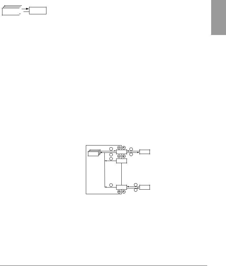
VVDED303042NAR6/04 |
Section 3: Menus |
06/2004 |
Drive Control Menu drC- |
|
|
SEt-

Code |
Description |
|
|
Adjustment Range |
Factory Setting |
|
|
|
|
|
|
||
Ftd |
Motor frequency threshold above which the relay contact (R1 or R2) closes, |
0 to 500 Hz |
bFr |
|||
or output AOV = 10 V. R1, R2, or dO must be assigned to FtA. |
||||||
|
|
|
||||
|
|
|
|
|
||
ttd |
Motor thermal state threshold above which the relay contact (R1 or R2) closes, |
0 to 118% |
100% |
|||
or output AOV = 10 V. R1, R2, or dO must be assigned to tSA. |
||||||
|
|
|
||||
|
|
|
|
|
||
Ctd |
Motor current threshold beyond which the relay contact (R1 or R2) closes, |
0 to 1.5 In1 |
In1 |
|||
|
or output AOV = 10 V. R1, R2, or dO must be assigned to CtA. |
|
|
|||
|
Scale factor for display parameter SPd1/SPd2/SPd3 (see SUPmenu on |
0.1 to 200 |
30 |
|||
|
page 85) |
|
|
|||
|
|
|
|
|
||
|
|
|
|
|
||
|
Used to scale a value (such as motor speed) in proportion to the output frequency rFr. |
|
||||
|
If SdS ≤ 1, SPd1 is displayed (possible definition = 0.01). |
|
|
|||
|
If 1 < SdS ≤ 10, SPd2 is displayed (possible definition = 0.1). |
|
|
|||
|
If SdS > 10, SPd3 is displayed (possible definition = 1). |
|
|
|||
|
If SdS > 10 and SdS x rFr > 9999: |
|
|
|||
SdS |
|
SdS x rFr |
|
|
||
|
Display of Spd3 = |
|
(to 2 decimal places). |
|
|
|
|
1000 |
|
|
|||
|
|
|
|
|
||
|
For example, if SdS x rFr equals 24,223, the display shows 24.22. |
|
|
|||
|
If SdS > 10 and SdS x rFr > 65535, the display shows 65.54. |
|
|
|||
|
Example: Display motor speed for a 4-pole motor, |
|
|
|||
|
1500 rpm at 50 Hz (synchronous speed): |
|
|
|||
|
SdS = 30 |
|
|
|
|
|
|
SPd3 = 1500 at rFr = 50 Hz |
|
|
|||
|
|
|
|
|
|
|
SFr |
Switching frequency |
|
See page 32. |
2.0 to 16 kHz |
4 kHz |
|
|
|
|
|
|
||
This parameter can also be accessed in the drCmenu. |
|
|
||||
|
|
|
||||
|
|
|
|
|
|
|
1 In is the nominal drive controller current indicated on the drive controller nameplate.
DRIVE CONTROL MENU drC-
|
ENT |
ESC |
Standard motor frequency |
|
|
bFr |
|
drC- |
|
|
|
ESC |
ENT |
|
|
|
ESC |
|
|
|
|
tAI |
|
|
ESC |
ESC |
Return to factory settings/restore |
|
|
FCS |
|
|
|
configuration |
|
|
|
ENT |
With the exception of tUn, drive control parameters can only be modified when the drive controller is stopped and no run command is present. This menu can be accessed with the access locking switch on the remote keypad display in the  position. Drive controller performance can be optimized by:
•Setting the drive control parameters to the values on the motor nameplate
•Performing an auto-tune operation (on a standard asynchronous motor)
ENGLISH
© 2004 Schneider Electric All Rights Reserved |
29 |

ENGLISH
Section 3: Menus |
VVDED303042NAR6/04 |
Drive Control Menu drC- |
06/2004 |
|
|
drC-

Code |
Description |
|
|
|
|
|
|
Adjustment Range |
Factory Setting |
||
|
|
|
|
|
|
|
|
|
|
|
|
bFr |
Motor frequency |
|
|
|
|
|
|
50 or 60 Hz |
50 |
||
|
|
|
|
|
|
|
|
|
|
||
|
This parameter modifies the presets of the following parameters: HSP (page 26), Ftd (page 29), FrS (page 30), and tFr |
||||||||||
|
(page 32). |
|
|
|
|
|
|
|
|
||
|
|
|
|
|
|
|
|
|
|
|
|
|
Nominal motor voltage indicated on the nameplate |
|
|
Varies with drive |
Varies with drive |
||||||
|
|
|
controller rating |
controller rating |
|||||||
|
|
|
|
|
|
|
|
|
|
||
|
|
|
|
|
|
|
|
|
|
|
|
UnS |
ATV31•••M2: 100 to 240 V |
|
|
|
|
|
|
|
|
||
ATV31•••M3X: 100 to 240 V |
|
|
|
|
|||||||
|
|
|
|
|
|||||||
|
ATV31•••N4: 100 to 500 V |
|
|
|
|
|
|
|
|
||
|
ATV31•••S6X: 100 to 600 V |
|
|
|
|
|
|
|
|
||
|
|
|
|
|
|
|
|
|
|
||
|
Nominal motor frequency indicated on the nameplate |
|
10 to 500 Hz |
50 Hz |
|||||||
|
|
|
|
|
|
|
|
|
|
|
|
|
The ratio |
UnS (in volts) |
must not exceed the following values: |
|
|
|
|||||
|
|
|
|
|
|
||||||
|
FrS (in Hz) |
|
|
|
|||||||
|
|
|
|
|
|
|
|
|
|
||
FrS |
ATV31•••M2: 7 |
|
|
|
|
|
|
|
|
||
|
|
|
|
|
|
|
|
|
|||
|
ATV31•••M3X: 7 |
|
|
|
|
|
|
|
|
||
|
ATV31•••N4: 14 |
|
|
|
|
|
|
|
|
||
|
ATV31•••S6X: 17 |
|
|
|
|
|
|
|
|
||
|
NOTE: Changing the setting of bFr to 60 Hz also changes the setting of FrS to 60 Hz. |
|
|||||||||
|
|
|
|
|
|
|
|
|
|
|
|
nCr |
Nominal motor current indicated on the nameplate |
|
|
0.25 to 1.5 In1 |
Varies with drive |
||||||
|
|
|
|
|
|
|
|
|
|
|
controller rating |
|
Nominal motor speed indicated on the nameplate |
|
|
0 to 32760 rpm |
Varies with drive |
||||||
|
|
|
controller rating |
||||||||
|
|
|
|
|
|
|
|
|
|
|
|
|
|
|
|
|
|
|
|
|
|
|
|
|
0 to 9999 rpm, then 10.00 to 32.76 krpm |
|
|
|
|
||||||
|
If the nameplate indicates synchronous speed and slip (in Hz or as a percentage) instead of nominal speed, calculate nominal |
||||||||||
|
speed as follows: |
|
|
|
|
|
|
|
|
||
|
Nominal speed = Synchronous speed x |
|
100 - slip as a% |
|
|
|
|||||
|
|
|
|
|
|
|
|||||
nSP |
|
|
100 |
|
|
|
|||||
or |
|
|
|
|
|
|
|
||||
|
|
|
|
|
|
|
|
|
|||
|
Nominal speed = Synchronous speed x |
50 - slip in Hz |
(50 Hz motors) |
|
|||||||
|
|
|
|
||||||||
|
|
50 |
|
||||||||
|
or |
|
|
|
|
|
|
|
|||
|
Nominal speed = Synchronous speed x |
|
|
60 - slip in Hz |
(60 Hz motors) |
|
|||||
|
|
|
|
||||||||
|
|
60 |
|
||||||||
|
|
|
|
|
|
|
|
|
|
|
|
|
|
|
|
|
|
|
|
|
|
|
|
COS |
Motor power factor indicated on the nameplate |
|
|
0.5 to 1 |
Varies with drive |
||||||
|
|
controller rating |
|||||||||
|
|
|
|
|
|
|
|
|
|
|
|
|
|
|
|
|
|
|
|
|
|
|
|
1 In is the nominal drive controller current indicated on the drive controller nameplate.
30 |
© 2004 Schneider Electric All Rights Reserved |
 Loading...