

Page 1

c Copyright TeleMatrix Inc.2004
SINGLE LINE
TRIMLINE
TELEPHONE
SET
USERS GUIDE
Page 2

INTRODUCTION
Congratulations on the purchase of your
TeleMatrix Trimline telephone. This
telephone is a precision electronic device
designed and manufactured with the highest
quality components and workmanship that
requires minimum maintenance. please be
sure to read the contents in this user’s guide
to become familiar with its features and
functionality.
1
Page 3

CONTENTS
Table Of Contents
Introduction 1
Features 3
Controls 4
Definition Of Controls 5
Installation 6
Parts Checklist 7
Wall Mounting 10
Permanent Mounting 12
Switch Setting 13
Care & Maintenance 17
Service 18
Warranty 19
2
Page 4

FEATURES
• Single Line Operation
• Tone/Pulse Dialing (selectable)
• Message Waiting Lamp (90VDC Neon)
• Convenient Data Port
• Handset Volume Control
• Flash Function (600mS)
• Dial In Handset
• Last Number Redial
• Hi/Low Ringer Volume Control
• Desk Or Wall Mountable
• Secured, Permanent Mounting Option
• Fully Modular
• Haring Aid Compatible
• 90VDC Neon or low Voltage LED Selectable
Selectable Message waiting
3
Page 5
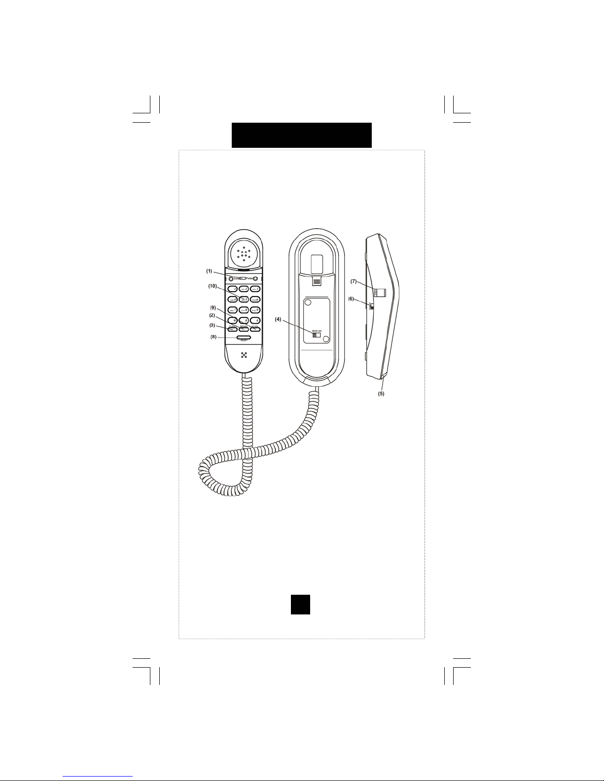
CONTROLS
4
Page 6

DEFINITION OF CONTROLS
1. Tone/Pulse Switch
Used to select touch-tone or rotary pulse dialing.
2. Redial key
Used to automatically re-dial the last number dial.
3. Flash Key
Provide a 600mS time line break.
4. Message waiting selector switch
Select optional 90VDC Neon or low voltage LED
message waiting.
5. Message Waiting Lamp
Visual indicator to tell you that a message is waiting
or that the line is ringing.
6. Ringer Volume Control
Switch to adjust the loudness or the ringer.
7. Data Port
Used for plugging in a laptop, modem, fax, etc.
8. Line Reset Key
Used to reset the line to place another call.
9. Handset Volume Control
Amplifies the volume of the receiver.
10. Dialpad
Large keys used for outbound dialing.
5
Page 7

INSTALLATION
Caution
• Never install telephone wring during a lightning
storm.
• Never install telephone jacks in wet location
unless the jack is specifically designed for wet
locations.
• Never touch un-insulated telephone wires or
terminal unless the telephone line has been
disconnected at the network interface.
• Use caution when installing or modifying
telephone lines.
6
Page 8

INSTALLATION
Parts Checklist
The following parts are packaged with your
TeleMatrix Trimline Telephone:
1. 15-foot Modular telephone line cord.
2. 3-inch Modular telephone line cord.
3. 10-foot Modular coiled handset cord.
7
Page 9

INSTALLATION
Connecting The Line Cord
Plug one end of the 15-foot modular telephone
line cord into the receptacle on the bottom of
the base unit. Ro ute the cord through the cord
channel provided. Plug the remaining end of
the line cord into a standard telephone outlet.
8
Page 10

INSTALLATION
Connecting The Handset Cord
Plug one end of the modular coiled handset
cord into the receptacle located on the left
side of the base unit. Plug the remaining end
into the receptacle on the handset.
9
Page 11

INSTALLATION
Wall Mounting
The TeleMatrix Trimline telephone can be wall
mounted to a standard telephone wall jack plate.
Using the 3-inch line cord , plug one end into the
receptacle on the bottom of the base unit. The
remaining end will plug into the wall jack. Carefully
align the slots on the bottom of the base unit with
the wall mount studs on the jack plate. Once aligned,
slide the base unit onto the studs and snap the base
unit into place.
10
Page 12

INSTALLATION
Handset Retaining Clip
The handset retaining clip must be activated to
hold the handset when wall mounting the
telephone. To activate, remove the clip, rotate it
180º and snap it back into place.
11
Page 13
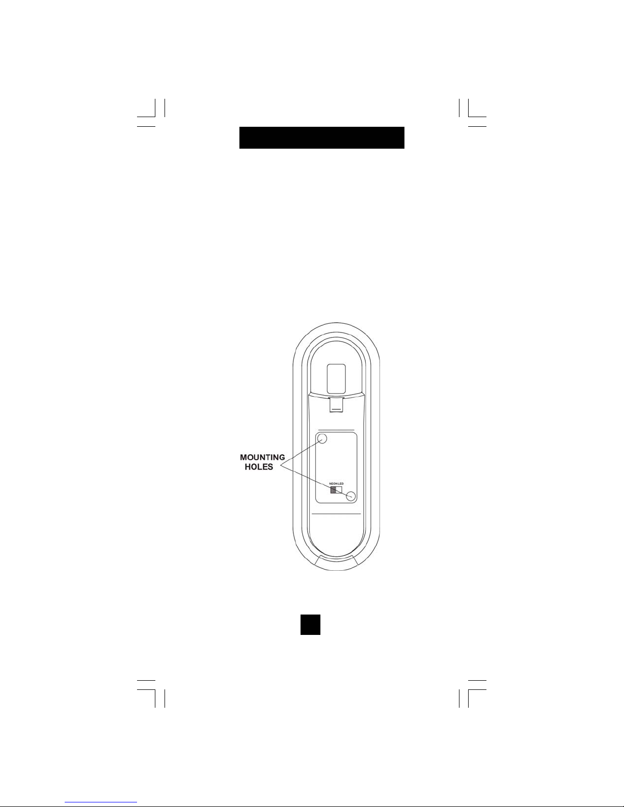
INSTALLATION
Secure Mounting Option
The TeleMatrix Trimline base unit can be perma nently attached to the wall using screws. This
mounting option is ideal for areas requiring security.
Underneath the index card are (2) mounting holes.
To locate, remove the clear plastic overlay and the
paper index
12
Page 14

SWITCH SETTING
Tone/Pulse Switch
The Tone/Pulse switch is located underneath a cover
plate located on the handset. Use a sharp pointer to
remove the switch cover plate to expose the switch.
Set the switch to the proper dialing mode that is com patible to your line service. If your lines are equipped
with “touch-tone” service, set the switch to the “Tone”
position. If you do not have “touch-tone” service, set
the switch to the “pulse” position. The “Pulse” setting
will electronically simulate rotary dialing.
13
Page 15

SWITCH SETTING
Message Waiting Switch
This telephone is standard equipped to support
eight high voltage (90VDC Neon) or low voltage
(LED) Message waiting systems, A selector
switch is provided underneath the faceplate for
security. The options are:
NEON = 90 VDC NEON
LED = LOW VOLTAGE
Note: The switch is factory set to the “Neon”
position.
14
Page 16

SWITCH SETTINGS
Ringer Volume Control Switch
There is a slide switch located on the right side
of the base unit that is used to adjust the loudness
of the ringing sound. A “low” and “high” setting
are provided . Select the desired loudness by
sliding the switch in the appropriate position.
15
Page 17

CARE & MAINTENANCE
Keep the telephone dry. If it gets wet on the
outside, wipe it dry immediately. Liquids
might contain minerals that can corrode the
electronic circuits. Do not touch the unit if
submerged in water. Call for assistance.
Use and store the telephone only in normal
temperature environments. temperature extremes can shorten the life of electronic devices, damage batteries, and distort or melt
plastic parts. Avoid direct sunlight.
Keep the telephone away from excessive
dust and dirt that can cause premature wear
of parts.
Wipe the telephone with a damp cloth occasionally to keep it looking new. Do not use
harsh chemicals, cleaning solvents, or
strong detergents to clean the unit.
16
Page 18

SERVICE INFORMATION
When problems arise during installation or service
that cannot be resolved using this or related
documents, contact the TeleMatrix Priority Care Department, Monday through Friday, 8:30a.m. 4:30p.m. MST:
Toll Free: 1-800-462-9446
Direct: 719-638-8821
Fax: 719-638-8815
www.telematrixusa.com
Many times a problem is either installation or user
related. Please contact TeleMatrix PRIOR to sending
a telephone to our service center for repair. In the
unlikely event th a t a factory repair is necessar y:
1. Include a brief description of the problem that you
are experiencing.
2. Include a proof of purchase for a repair under
warranty.
3. Send the telephone prepaid by UPS or Parcel Post,
insured to:
TeleMatrix, Inc.
Priority Care Center
5025 Galley Road
Colorado Springs, Colorado 80915
TeleMatrix will pay r eturn postage on the repaired
telephone. Allow 2-3 w eeks for delivery. When immediate replacement is required, see our FastLane
replacement policy on our internet site.
SM
17
Page 19

FCC REQUIREMENTS
1. The Federal Communications Commission (FCC) has estab-
lished Rules which permit this device to be directly connected to
the telephone network. Standardized jacks are used for these
connections. This equipment should not be used on party lines or
coin lines.
2. If this device is malfunctioning, it may also be causing harm
to the telephone network: this device should be disconnected
until the source of the problem can be determined and until repair has been made. If this is not done, the telephone company
may temporarily disconnect service.
3. The telephone company may make changes in its techni cal
operations and procedures: if such changes affect the compatibility or use of this device, the telephone company is required to
give adequate not ice of the changes.
4. If the telephone company requests information on what
equipment is connected to th ei r lines, inform them of:
(a) The telephone number that the unit is connected to.
(b) The ringer equivalence number.
(c) The USOC jack required, and
(d) The FCC Registration Number.
Items (b) and (d) are indicated on the label. The rin ger eq uiva-
lence number (REN) is used to determine how many devices
can be connected to your t elephone line. In most areas, the sum
of the REN’s of all devices on any one line should not exceed
five (5.0). If too many devices are attached , th ey may not ring
properly.
Service Requirements
5. In the event of equipment malfunction, all repairs should be
performed by our company or an authorized agent. It is the responsibility of users requiring service to report the need for
service to our Company or to one of our authorized agents Service can be facilitated through our office at:
TeleMatrix, Inc.
5025 Galley Road
Colorado Springs, CO. 80915
800-462-9446
719-638-8821
18
Page 20

WARRANTY
STATEMENT OF LIMITED WARR ANTY
TeleMatrix, Inc. (TMX) warrants to its [original end customer] [purchaser] that Spectrum, Spectrum Plus and Marquis branded products manufactured by
TMX are free from defects in materials and workmanship for five (5) years after the date of purchase, and Regency branded products manufactured by
product.
TMX are free from defects in materials and workmanship for three (3) years, other than the following products for which the warranty period sha ll b e o ne
(1) year: handse t bat te ries, e it her Ni Cd or Ni MH, use d in T MX c ordle ss p roduct s. If a prod uct fails thi s war rant y duri ng t he wa rrant y pe ri od, T MX will , at
its option, either repair or replace the defective product or parts, or deliver replacements for defective products or parts on an exchange basis at no
additional charge to the customer except as set forth below. Repair parts or replacement products may be either new or reconditioned. Products o r par t s
returned to TMX under this warranty will become the property of TMX. Warranties on p roducts repaired by TMX expire at the termination of the o riginal
warranty period. This limited warranty does not cover: 1. Products or parts which are damaged, abused or misused;
2. Any damage resulting from improper installation, maintenance or operation of the product;
3. Damage resulting from unauthorized modification or repair of the product, or from improper connection of the product to other equipment;
4. Cords, connectors and replaceable batteries;
8. Products or parts which are not owned and used by the original end user customer. The cost and risk of loss or damage for sending the product to TMX will be borne by the customer. TMX EXPRESS LY DI SCLAI MS ALL WARR ANTI ES EX CEPT T HE LI MITED WARR ANTY SET F ORTH H EREI N, WHI CH IS THE SOLE AND E XCLU SIVE W ARRANT Y
5. Damage in transit to the TMX repair facility;
6. Any product or part unless proof of date of purchase is submitted with the product when returned for warranty repair; or
7. Costs incurred by the cust omer in re moving and shippi ng the p roduct to TMX for repair o r replace ment, and costs of reinsta llation of the
OF THE PRO DUCT , AND I S IN L IE U OF AL L O T HER W ARR ANTI ES, W HET HER O RAL OR W RIT TEN , E XPRE SS OR IMPL IED, OR ST AT UTOR Y . TH ERE AR E NO
IMPLIED WARRANTI ES OF MER CHANTABI LITY OR FITNESS FO R A PARTIC ULAR PUR POSE. T HE CUSTOM ER’S SOL E REMED Y UNDER T HE TMX WARR ANTY
SHALL BE REPAIR OR REPLACEMENT AS PROVIDED ABOVE. IN NO EVENT WILL TMX BE LIABLE TO CUSTOMER OR ANY OTHER PARTY FOR ANY INDIRECT,
INCIDENTAL OR C ONSEQUENTIAL DAMAGE S, INCLUDING, WITHO UT LIMITATION, DAMAGE S OF LOST PROFITS, LOST R EVENUES, LOSS OF USE O F
FACILITIES OR EQUIPMENT, OR COST OF SUBSTITUTE EQUIPMENT ARISING OUT OF THE USE OR INABILITY TO USE THIS PRODUCT, EVEN IF THE CUS-
TOMER HAS ADVIS ED TM X OF TH E P OSSI BILI TY O F S UC H DA MAG ES. TM X L IAB ILIT Y FO R DA MAGE S S HALL NO T E XCEE D T HE PUR CHAS E PR ICE OF T H E
DEFECTIVE PRODUCT. This limited warranty is non-transferable without the prior written approval of T MX. It gi ves the customer specific legal rights. The cus tomer may have
other rights which vary under local law. Some jurisdictions may not allow limitations on the term of an implied warranty or exclusions or limitations of
incidental or consequential damages.
19
 Loading...