


SPECTRUM PLUS SP750

1

This pa ge is intentionally left blank
2

Congratulations on the purchase of your TeleMatrix Spectrum
TM
PLUS
SP750 includes advanced features that are suitable in today’s
business environment. TeleMatrix designed the Spectrum PLUS
model SP750 Caller ID telephone. The Spectrum PLUSTM
TM
SP750 to be simple to install and easy to use.
Your Spectrum PLUS
TM
SP750 telephone is a precision electronic
device that requires minimum maintenance. Please be sure to
read this user’s guide to become familiar with the wiring and
functionality of this product.
As specified by FCC regulation, we are required to inform you of specific
governmental and compliance regulatory requirements, safety notices,
safety instructions and other informative information. TeleMatrix, Inc.
provides this information in a separate manual. We pack the separate
Compliance and Safety Manual within each outer box or product box when
shipped.
Prior to reading this operation manual and prior to setting up your
telephone, please refer to the Compliance and Safety Manual.
3

Features .........................................………..................................... 5
Controls ……................................................................................. 6
Parts List ………………………………………………………………………………………………... 10
Installation ....……......................................................................... 11
Wall Mounting .....…..............................……................................... 15
Switch Settings .....….......................….…....................................…. 17
Programming ..……..............................…....................................... 18
Headset Installation and Operation……........…................................... 36
LCD Display/Caller Identification …………..…..…………………………………...... 38
Operation ………………………………………………………………………………………………. 56
Care and Maintenance ………………………………………………………………………….. 65
Service …………………………………………………………………………………………………… 66
Warranty ……………………………………………………………………………………………….. 67
FCC Compli ance and Safety In struction s, Warranty a nd Service Inf ormati on
may be found in a separate manual within this package. If these/this
manual is not found in this products packaging, then immediately contact
your local supplier
4

• Two Line Operation
• SteelTrap
• FreeSpeech
TM
Memory Technology (No Batteries Required)
TM
Talk Feature: Allows Free Toggle between Handset, Headset and Speakerphone
• Administrator Programming (Fixed ): Dialing Acce ss Number, Local Ar ea Code Recognition , Live Keypad Dialing, Re strict
1+ Toll Restriction, Pause Timing, Flash Timing, Voi ce Mail Access including Secure Pass word Dialing, CID Records Log
• User Programming (Variable): Manual Date and Time, Multiple Language Options, Ring Volume, Ring Tone Adjustment,
Speed Dial Memory
• Large, Contrast Adjustable , Backlit LCD Display Shows:
- 100-Memory Phonebook with Auto Entry from 100 Scrolling Caller ID Call Re cords
- Programmable Date & Time
- Edit Capable Name and Number
- Number of New Messages and Total Messages
- Dialing Verification and Active Line Status
- Elapsed Call Timer
- Functional Icons
• Type II Caller ID (Caller ID with Call Waiting)*.
• 100 Name and Number Call Log with Editing, Scrolling, Call Back and Delete
• 100 Name and Number Edit Capable Phonebook
• Visual Message Waiting Indication* – Auto Detection for SDT, FSK or NEON,
• TouchLite
TM
One Touch Message Retrieval Key
LED uses switch.
• 2-Way Speakerphone (Half Duplex)
• Headset Port with ON/OFF Switch (built-in Amplifier)
• Conference Call Feature
• Microphone Mute
• Eleven (11) Speed Dial Keys
• Electronic Hold with LED Indicator (Line Hold or System Hold)
• Audible Ring Tone (4 selections)
• Speaker, Headset, and Ringer Volume Control (8 s e lectio ns includ ing OFF)
• Convenient Data Port (on line 2)
• ADA Compliant Handset with 8-step Volume Control
• Disconnect Key to Activate New Call
• Last Number Redial
• Programmable Flash Key
• Programmable Pause Key
• Wall Mount or Desktop Placement
5
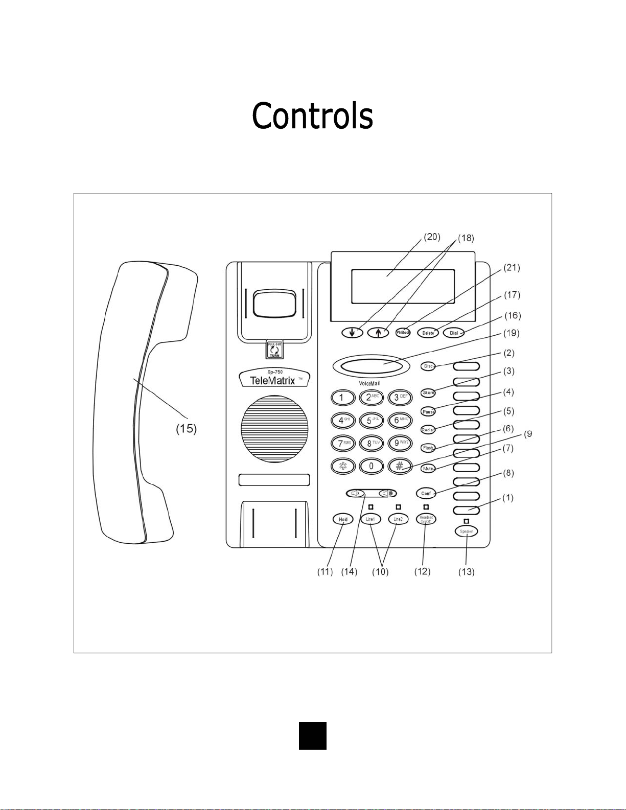
TOP PANEL
6

1. Speed Dial Feature Keys……………..…. Eleven (11) one-touch keys used for speed dialing.
2. Disconnect Key ……………………...…….. Used to disconnect the line or place a new call.
3. Store Key……………………………….….…... Used to program user features.
4. Pause Key ...............................…. Used to place a timing delay when dialing.
5. Redial Key ......................……………. Redials the last number dialed.
6. Flash Key ..................……………..…. Provides a timed line break
7. Mute Key …………………………….………... Disables the handset and speaker phone microphones.
8. Conference Call Key……………………..… Used for conference calls.
9. Numeric Dial Pad ………………...………. Used for dialing.
10. Line 1 and Line 2 …………………….……. Used to select line 1 or line 2.
11. Hold Key ………………………………..…….. Lighted key used for placing callers on hold.
12. Headset ON/OFF Key ……………………. Lighted key used to turn the headset ON or OFF.
13. Speaker Key .………………................ Used to turn the speakerphone ON or OFF.
14. Volume Bar …………………..………………. Adjusts the loudness of the handset receiver, the head
set, and/or the speaker.
15. Handset ……………………………….……... Hearing-aid compatible handset.
16. Dial Key ..………................……....... Used to automatically dial the number displayed on the
LCD.
17. Delete Key ……………………………..……. Deletes stored Caller ID records and Phonebook
(PhBook) records.
18. Up and Down Scroll Key ..….......... Used to scroll Caller ID and Phonebook (PhBook)
records.
TM
19. Touchlite
Key...……………………....... Message Waiting Lamp (LED indicator) that blinks
to indicate a new message in the user’s voice mail
box (user must be subscribed to a messaging system).
20. LCD Display ...............……........... Large adjustable back-lit display that shows Caller ID,
number of calls received, date and time, and call log.
21. Phonebook (PhBook) Key ……………. Used to access names and numbers in the Phonebook
(PhBook) directory.
7
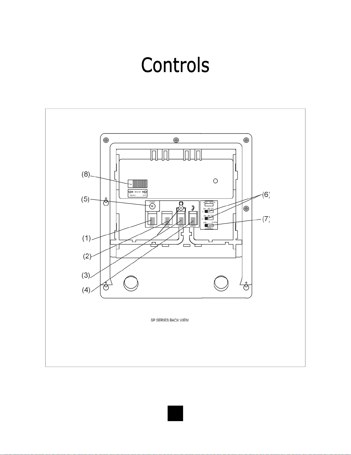
BOTTOM PANEL
8

1 Data Port ..................................... Convenient port to connect a computer,
modem, fax or answering device.
2 Line Jack ………………………………………... Modular receptacle for connecting the
line cord.
3. Headset Jacks ............................. Convenient RJ port or 2.5mm coaxial port used
to connect an optional headset.
4 Handset Jack ............................... Connection for handset coil cord.
5. Power Adapter Receptacle ……..……… For optional coaxial power adapter.
6 Low Voltage MW Switch ………………… Used to select LED Message Waiting On or OFF.
7 Hold Key Switch ……………...…………… Used to select standard line hold or
programmable system hold.
8 Elevation Stand Lock ……………………… Used to “lock” the elevation stand.
9
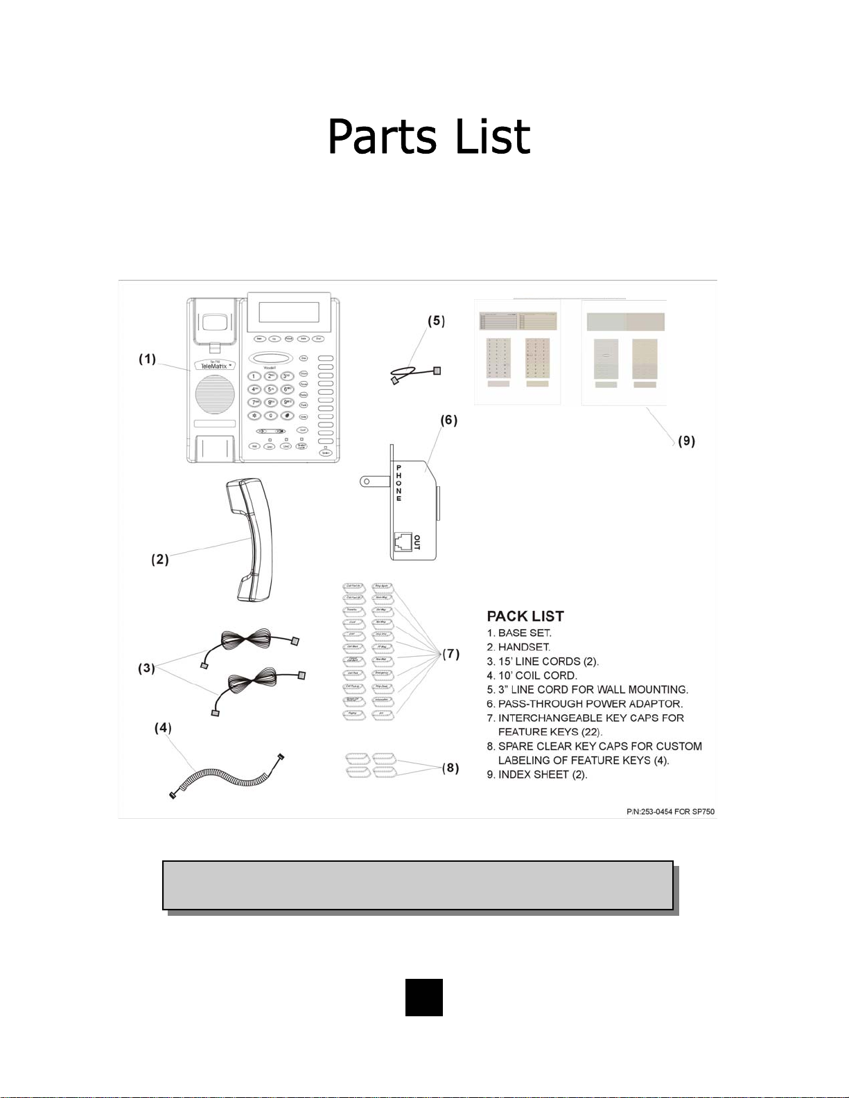
Parts Check List
The following parts are included with the Spectrum PLUS
TM
SP750:
NOTE: Spectrum PLUSTM Line Cords are 6-Pin 6-Conductor Line cords
(6P6C line cord). Replacement Line Cords must be same.
10

Caution
• Never install telephone wiring during a lightning storm.
• Never in stall telephone jack s in wet locations unless the jack is
specifically designed for wet locations.
• Never touch uninstalled telephone wires or terminals unless the
telephone line has been disconnected at the network interface.
• Use ca ution when installing or modifying telephone lines.
Power Outlet Configuration
The Spectrum PLUS
outlet (60Hz).
TM
Series telephone requires external power from a standard 120V
IMPORTANT!
The telephone will not functio n if the line cord connections are not co rrect. Be sure that
the telephone line cord connections are not reversed (“LINE”/”PHONE”). Attach the line
!
cords to the power adapter and the wall before connecting to the telephone. Spectrum
TM
PLUS
Cords must be same.
Line Cords are 6-Pin 6-Conductor Line cords (6P6C line cord) . Replacement Line
11
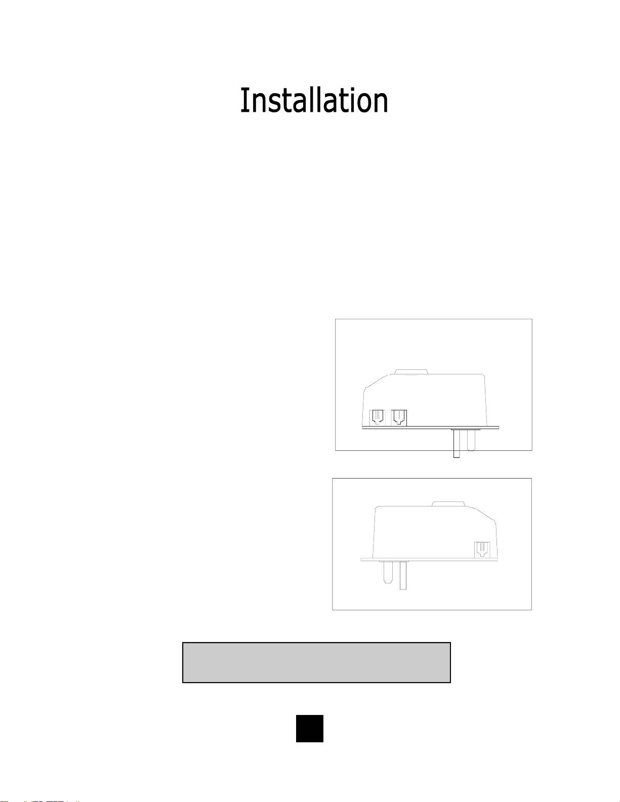
120V AC Outlet Recovery Power Adapter (provided)
The 120 VOLT AC OUTLET RECOVERY POWER ADAPTER is an featured TeleMatrix
product. It provides both the telephone lines and the power source in one cable
(6P6C line cord) and is designed to recover the use of the power outlet.
Connector Configuration
The 120 Volt Outlet Recovery Power Adapter has two (2) modular jacks. One
jack is labeled “LINE” and the other jack is labeled “PHONE”. These jacks allow
for a fully modular ins tallation.
Power Adapter “LINE” Connection
The power adapter “LINE” connection is
used to connect the telephone line from
the wall jack to the power adapter.
Using one of the 15-foot modular
telephone li ne cords, connect one end of
the cord to the RJ14 telephone jack on
L2L1 +L2
NEL
_
the wall or base board. The remaining
end of the cord plugs into the “LINE” side
of the power adapter.
Power Adapter “PHONE” Connection
The power adapter “PHONE” connection
is used to provide both the telephone
lines and the power source to the
telephone. Using one of the 15-foot
modular telephone line cords, plug one
end of the line cord into the back of the
telephone. Plug the remaining end to
the power adapter jack labeled
“PHONE”.
Troubleshooting Note: If there is no power to the telephone
after connecting the line cords, c heck to see if the line cords
are inserted on the opposite sides of the adapter.
12
OUT
EHNOP
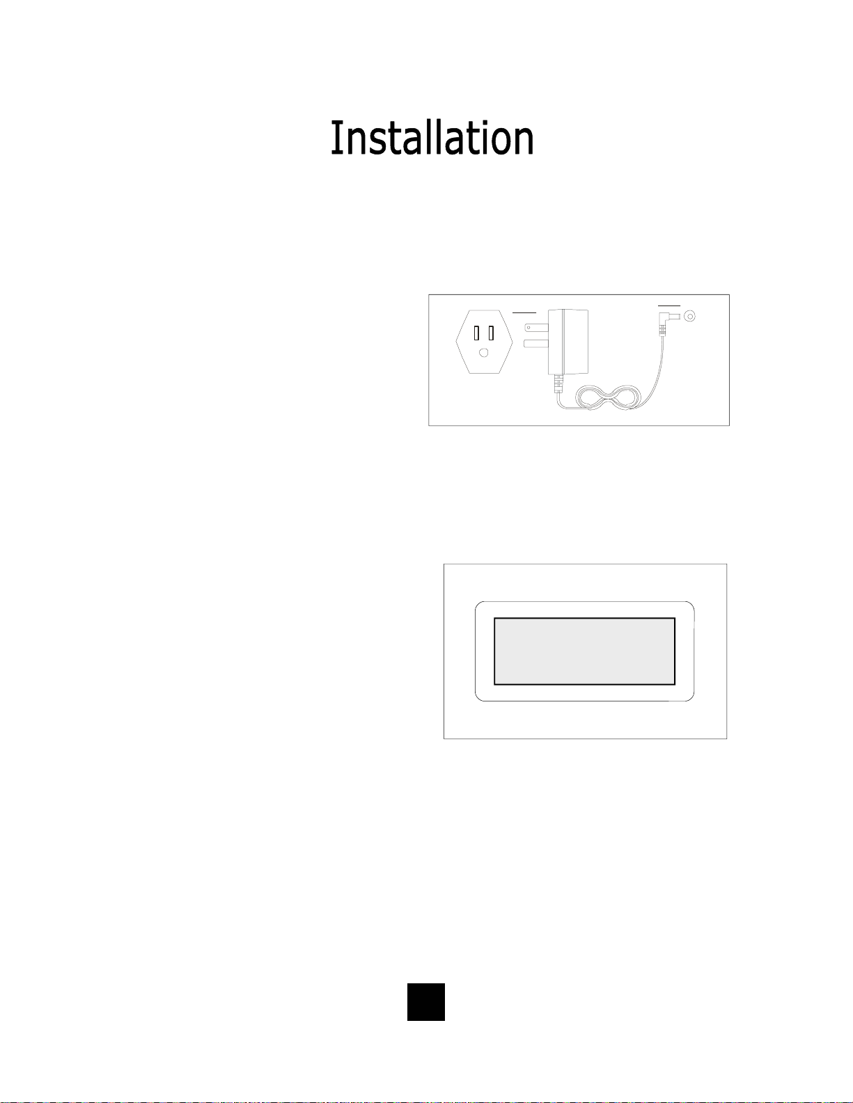
Installing The Wall Power Adapter
(Optional Component)
This compon ent i s b est used wh en wall
mounting the telephone. To install,
simply plug the power adapter into a
standard 120V AC power outlet. A
mounting hole is provided to secure
120V AC POWER
the power pack to the AC wall outlet.
Plug the AC power pack directly into
the wall outlet and then plug the coaxial connector into the receptacle
marked “POWER” located on the back
of the telephone.
Comple ting the Power Insta l lation
If the installation is correct, the
information shown at the right will be
displayed on the LCD.
If the LCD does not display words and
numbe rs , c he ck y our p ow er
connections.
POWER
ORDER SEPERATELY
02/27 pm12:26
-00- -00-
NEW TOTAL
13

Connecting the Handset Cord
A 10-foot modular coil handset cord is
provided. (Be sure that the wall/desk
elevation stand has not been attached).
To install the cord, simply plug the
short end of the handset cord into the
modular jack on the handset. The long
end of the handset cord plugs into the
jack labeled “Handset” located on the
bottom of the Spectrum PLUS
TM
base
unit. Place t he line cord into the ha ndset coil cord channel located directly
below the jack.
Installing the Keycaps
Twenty-two (22) preprinted named
feature keycaps are provided to identify
the speed dial key.
There are eleven (11) clear keycaps
already installed. To install preprinted
keys, remove the clear keycap by
simply pulling up. Replace with the
preprinted keycaps or place hand
written paper index sheets under a
clear keycap. P rogram each speed dial
key for the specific function of the key.
CLEAR "SNAP-ON" KEY CAP
OR SILK SCREEN KEY CAP
PLASTIC TOP CAB INET
Handset Cord
PLASTIC TOP CABINET
PLASTIC KEY TOP
NOTE: For speed dial programming instructions,
see the sect ion on “Pro gramming Proc edure For
Spectrum PLUS
manual.
tm
Speed Dial Features” in this
There are four (4) additional clear keycaps and two (2) index sheets provided as
spares. Use t hese for y our own pe rsonal speed d ial iden tities. Write th e speed di al
name on the blank speed dial index cards and insert into the blank keycaps. Place
the keycap on the correct memory speed dial location. (see index sheets provided
in box).
The twenty-two preprinted keycap names are below:
Call Fwd On Call Back Paging Skip Msg Information
Call Fwd Off Cancel Call Back Ring Again FF Msg 911
Transfer Call Park Save Msg Rew Msg
Conf Call Pick-up Del Msg Emergenc y
DND Group Call Pick-up Rpt Msg Help Desk
14
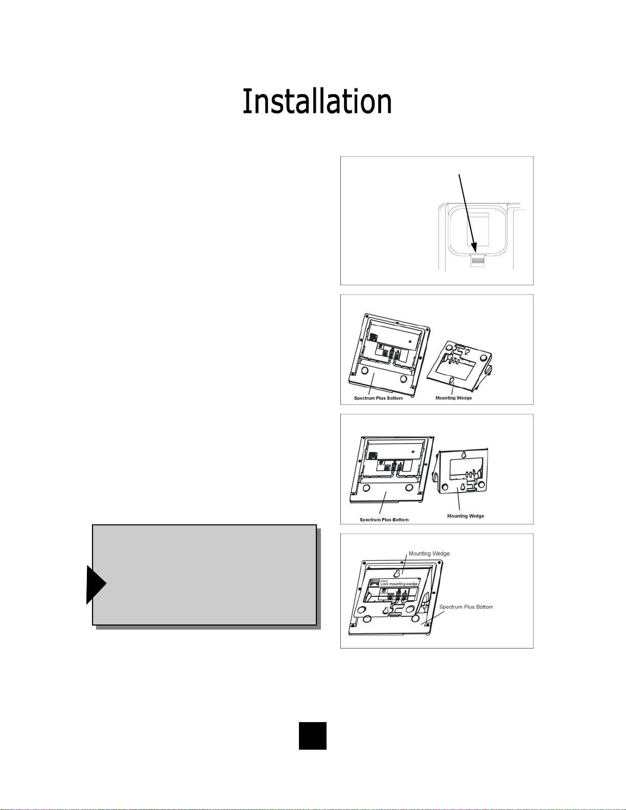
Wall Mounting the Spectrum PLUSTM Telephone
The Spectrum PLUSTM was designed to be
conveniently wall mounted without requiring
additional hardware.
Follow these easy steps:
1.The handset retaining clip must be in the correct
position to secure the handset into the handset
cradle. Engage the clip with your fingers and pull
the clip forward (towards you), rotate the clip 180º
and snap the clip back into place (figure 1). The
retaining clip cannot be removed.
1. UNSNAP
2. ROTATE 1 80 .
3. SNAP INTO PLA CE.
1.LIFT CLIP OUT WITH
FINGERS. IT CANNOT BE
REMOVED BECAUSE IT
IS SPRING LOADED.
2. ROTATE THE
0
CLIP 180
AND
IT WILL SMAP
BACK INTO THE OPPOSITE POSITION. AN
RETAINER CLIP
NOTE: CLIP IS
figure 1
2. The Spectrum PLUSTM has provisions for a
mounting wedge that must be correctly positioned.
This wedge allows the telephone to be viewed at a
correct angle when the phone is wall mounted.
Remove the wedge from the ph one base (figure 2).
3. Secure the line cord, coil cord and any wiring in
place prior to installing the wall mount wedge. The
wall mount base has extra large wiring channels
and strain relief poles for containing the wires in a
neat and orderly way. Wrap the wires around the
strain relief poles and then secure the wires
through the channel.
4. To wall mount, place the narrow edge at the top
edge of the phone base and slide the wedge upward into place (figure 3).
5. Lock the wall mount into position by sliding the
locking button to the r ight (figure 4).
Note: A 6-inch line cord is provided for when
the telephone is to be wall mounted. Connect
one end of the line cord to the phone jack and
the other end to the wall jack. Be sure to connect the power cord and line cords before plac-
ing mounting wedge on the bottom base. An
!
optional coaxial power supply can be used in
place of the supplied power supply. See your
local distributor for information.
Replace Mounting Wedge
figure 2
Replace Mounting Wedge
figure3
Lock Mounting Wedge
figure 4
Desk Mounting
To install the wedge for desk mounting, be sure the lock mechanism is positioned to the left
clear of the locking arm. Place the wedge in the slots, wide end toward top of phone base
unit, and slide the wedge upward into position. Lock the wedge into place.
15

Message Waiting Light Indicator
The Spectrum PLUS
TM
telephone has a
Message Waiting Light Indicator
Message Waiting (MW) Light Indicator (figure
1). The indicator will blink to indicate that a
new message is in the user’s voice mailbox.
The Spectrum PLUS
TM
supports the following
telephone or PBX supplied message waiting
signals:
1. Telephone Company VMWI Service* (FSK
signal compatible, subscription to local
telephone company is required).
2. Or, Audible Stutter Dial Tone (SDT) signals
provided by local telephone company.
3. Or, 90-Volt NEON message waiting light
indicator signal provided by a PBX.
4. Low Voltage LED m essage waiting light in-
dicator light signal is provided by a PBX
The PBX system or telephone servi ce provider
has to activate the voice mail feature for the
!
light to illuminate and work properly. Be sure
that your telephone service provider or PBX
system has the compatible messaging service
available in your area or facility.
figure 1
NOTE: The Spectrum PLUS
telephone automatically reads the
Message Waiting (MW) signals
supplied by your service provider.
The LED signal supplied by a PBX
must have the LED Voltage switch
which is located on the bac k of the
telephone in the correct
position to operate the LED. See
the next page for instructions.
TM
Use this feature when alerting another that a saved message is in voice mail for that person or
use this feature when you simply want to turn the light off.
Be Aware: If there is a new incoming message and the telep ho ne company co ntinue s to s e nd
f
a new signal this light will re-activate. This will occur only when there is a new voice mail that
has not been heard.
How To Use: When on-hook, Press the “*” key for 3 to 5 seconds and the Message LED will
automatically turn on. At any time press “*” key for 3 to 5 seconds ,Message LED will turn off.
*Definition: VMWI is Visual Message Waiting Ind ication. This optio n requires a
d
subscription to your loc al telephone service provider for TouchLite
Feature Note: Message ON/OFF Notification.
TM
to activate.
16

Low Voltage LED Switch
A low voltage LED switch is located on
the bottom of the phone. The switch
options are ON or OFF. The factory
default is OFF.
Line Voltage Switches
A voltage switch for each phone line is
located on the bottom of the phone.
The voltage options are 24 Volt, 48
Volt, or OFF. This voltage switch is
used to illuminate LED lamps on the
top side of the phone. It must be in
the correct voltage position to operate
the LED lamps. The factory default is
24 Volt.
System Hold Feature Option Switch
A feature switch for different hold
functions is located on the bottom of
the phone. The switch options are
standard “LINE Hold” or programmable
“System Hold”*.
The standard “Line Hold” allows for
normal hold function operation. The
programmable “System Hold”* feature
is used for optional PBX system
operations.
The switch default is set at the factory
as standard “LINE Hold”.
* Programming “System Hold” is an Administrator
function. To program System Hold, follow the
speed dial instructions in this manual. To store the
dialing pattern, press the HOLD key in place of the
memory location.
LOW VOLT MW
ON OFF
LOW VOLT MW
ON OFF
17

Programming Set Up Of the Spectrum PLUSTM Telephone
The Spectrum PLUSTM requires simple initial programming to set up the telephone.
One program mode is designed for Administrator set up and one program mode is for
User set up and use. Administrator programming features separate critical operating
set up information from the user telephone functions.
ENTER ACCESS NO. Set up pre-dialing number sequence, i.e. outside line.
ENTER AREA CODE Set up local area code to recognize local incoming calls.
LIVE DIALPAD
dialing, pressing dial key to activate.
Set up either using keypad dialing with automatic speaker activation, or using k ey pad
RESTRICT 1+ Long distance restriction. Restrict any outgoing number dialing that begins with a “1” .
FLASH TIME SET
Set up flash timing 100mS to 1000mS. Default 600mS.
PAUSE TIME SET Set up pause timing 1.0mS to 5.0mS. Default 3.6mS.
VOICE MAIL NO.
messages. PIN number characters will not be displayed.
Set up voice mail number. Add your PIN with seconds of wait time to get access to
CID RECORDS LOG SET Set up CID record log TOTAL or EACH.
18
Programming Set Up Of the Spectrum PLUSTM Telephone
The Spectrum PLUSTM requires simple initia l progr amming to set up the telephone.
The program is designed for one Administrator and one or more users. Administrator
programming features separate critical operating set up information from the user
telephone functions.
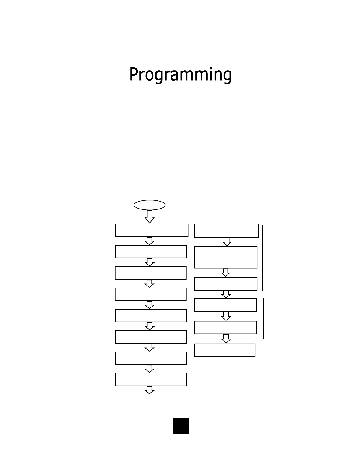
The Administrator Quick Program Guide for the Spectrum PLUSTM Telephone
The Spectrum PLUSTM Quick Programming Guide is a sum mary list of set up options.
Additional detailed instru ctions are pro vided in the manual.
Programming is initiated
by holding down the
“STORE” key for six
seconds.
STORE
Set up pre-dialing number
sequence, i.e. outside
Set up local area code to
recognize local inco ming
calls.
Set up either using keypad dialing with automatic
speaker activation, or
using key pad dialing,
pressing dial key to
activate.
Long distance restriction.
Restrict any outg o ing
number dialing that
begins with a “1” .
Set up flash timing
100mS to 1000mS.
Default 600mS.
Set up pause timing 1.0S
to 5.0S. Default 3.6S.
ENTER ACCESS NO.
ENTER AREA CODE
LIVE DIALPAD XXX
PRESS 1=ON 2= OFF
RESTRICT 1+
PRESS 1=YES 2= NO
FLASH TIME SET
PAUSE TIME x.x S
VOICE MAIL NO.
PIN NUMBER
SECOND OF WAIT?
CID RECORDS LOG
1 = TOTAL 2 = EACH
ALL SETUP OK
Set up voic e ma i l n u mb e r. Ad d
your PIN with seconds of wait
time to get access to messages.
PIN number characters will not
be displayed on the LCD.
Set up the Caller Log record
display to s how sa me caller
separately logged or show
same caller in one line display
with number of incoming total
calls.
19
Administrator and User Set Up of the Spectrum PLUSTM Telephone
The Spectrum PLUSTM requires simple initia l progr amming to set up the telephone.
The program is designed for one Administrator and one or more users. Administrator programming features separate critical operating set up information from the
user telephone functions.
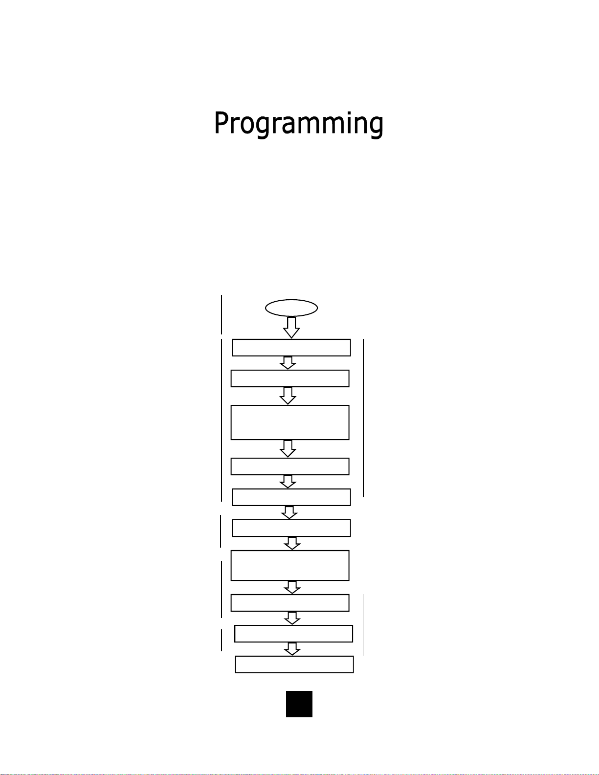
The Users Quick Program Guide for the Spectrum PLUSTM Telephone
The Spectrum PLUSTM Quick Programming Guide is a sum mary list of set up options.
Additional detailed instru ctions are pro vided in the manual.
Programming is initiated by quickly pressing the “STORE” key.
Set up date and time
Set up language
Set up ringing options of
ring tone (4 tones) and
ring volume (8 steps).
Press keypad numbe r
for sample of ringing
tone or volume.
Set up is complete.
STORE
SETUP MONTH:01
SETUP DAY:01
SETUP TI ME MODE
PRESS 1=12 2=24
AM=1 PM=2
SETUP HOUR:01
SETUP MINUTE:01
-1- -2- -3-
ENG FRA ESP
RING TONE 1- - 4
RING VOLUME 1- - 8
Note: the date and
time will automatically
set if your telephone
line is equipped with
Caller ID. The date and
time will be set by an
incoming ring.
Note: the software will
ask to select line 1 (L1)
or line 2 (L2). Each line
supports different tone
and volume settings.
ALL SETUP OK
20
Set up using keypad
dialing with automatic
speaker activation or
using key pad dialing
and pressing dial key to
activate.
Display indicates condition of ON or OFF, then next screen appears.
12/01 PM 12:00
LIVE DIALPAD ON
12/01 PM 12:00
PRESS 1=ON 2=OFF
LIVE DIALPAD XXX
PRESS 1=ON 2= OFF
LIVE DIALPAD Feature
(Administrator)
This feature sets up the telephone dialing
pad method.
When LIVE DIALPAD is OFF, and the
handset is ON HOOK, the user enters a
number on the keypad and then must
press the “DIAL” key to activate dial
tone.
When LIVE DIALPAD is ON, and the
handset is ON HOOK, the dial tone activates immediately upon pressing the keypad.
The handset can be lifted at any time to
activate the receiver.
To enable or disable LIVE DIALPAD ON.
1. Press and hold the “STORE” key for
6-seconds.
2. Press “STORE” multiple times until
the LCD displays “LIVE DIALPAD ON”.
3. Press “1=ON” to enable, or “2=OFF”
to disable.
4. To exit the program mode, press
“DISC” or continue to the end of programming by pressing the “STORE”
key multiple times unti l the display
reads “All Setup OK”.
Note: Programming can
only be performed when
!
the phone is on-hook
NOTE: The Live Dial Pad feature works only
when the handset is ON HOOK, it does not
!
work when the handset is OFF HOOK.
21
 Loading...