

Page 1

1
Page 2

This pa ge is intentionally left blank
2
Page 3

Congratulations on the purchase of your TeleMatrix Spectrum
TM
PLUS
SP750 includes advanced features that are suitable in today’s
business environment. TeleMatrix designed the Spectrum PLUS
model SP750 Caller ID telephone. The Spectrum PLUSTM
TM
SP750 to be simple to install and easy to use.
Your Spectrum PLUS
TM
SP750 telephone is a precision electronic
device that requires minimum maintenance. Please be sure to
read this user’s guide to become familiar with the wiring and
functionality of this product.
As specified by FCC regulation, we are required to inform you of specific
governmental and compliance regulatory requirements, safety notices,
safety instructions and other informative information. TeleMatrix, Inc.
provides this information in a separate manual. We pack the separate
Compliance and Safety Manual within each outer box or product box when
shipped.
Prior to reading this operation manual and prior to setting up your
telephone, please refer to the Compliance and Safety Manual.
3
Page 4

Features .........................................………..................................... 5
Controls ……................................................................................. 6
Parts List ………………………………………………………………………………………………... 10
Installation ....……......................................................................... 11
Wall Mounting .....…..............................……................................... 15
Switch Settings .....….......................….…....................................…. 17
Programming ..……..............................…....................................... 18
Headset Installation and Operation……........…................................... 36
LCD Display/Caller Identification …………..…..…………………………………...... 38
Operation ………………………………………………………………………………………………. 56
Care and Maintenance ………………………………………………………………………….. 65
Service …………………………………………………………………………………………………… 66
Warranty ……………………………………………………………………………………………….. 67
FCC Compli ance and Safety In struction s, Warranty a nd Service Inf ormati on
may be found in a separate manual within this package. If these/this
manual is not found in this products packaging, then immediately contact
your local supplier
4
Page 5

• Two Line Operation
• SteelTrap
• FreeSpeech
TM
Memory Technology (No Batteries Required)
TM
Talk Feature: Allows Free Toggle between Handset, Headset and Speakerphone
• Administrator Programming (Fixed ): Dialing Acce ss Number, Local Ar ea Code Recognition , Live Keypad Dialing, Re strict
1+ Toll Restriction, Pause Timing, Flash Timing, Voi ce Mail Access including Secure Pass word Dialing, CID Records Log
• User Programming (Variable): Manual Date and Time, Multiple Language Options, Ring Volume, Ring Tone Adjustment,
Speed Dial Memory
• Large, Contrast Adjustable , Backlit LCD Display Shows:
- 100-Memory Phonebook with Auto Entry from 100 Scrolling Caller ID Call Re cords
- Programmable Date & Time
- Edit Capable Name and Number
- Number of New Messages and Total Messages
- Dialing Verification and Active Line Status
- Elapsed Call Timer
- Functional Icons
• Type II Caller ID (Caller ID with Call Waiting)*.
• 100 Name and Number Call Log with Editing, Scrolling, Call Back and Delete
• 100 Name and Number Edit Capable Phonebook
• Visual Message Waiting Indication* – Auto Detection for SDT, FSK or NEON,
• TouchLite
TM
One Touch Message Retrieval Key
LED uses switch.
• 2-Way Speakerphone (Half Duplex)
• Headset Port with ON/OFF Switch (built-in Amplifier)
• Conference Call Feature
• Microphone Mute
• Eleven (11) Speed Dial Keys
• Electronic Hold with LED Indicator (Line Hold or System Hold)
• Audible Ring Tone (4 selections)
• Speaker, Headset, and Ringer Volume Control (8 s e lectio ns includ ing OFF)
• Convenient Data Port (on line 2)
• ADA Compliant Handset with 8-step Volume Control
• Disconnect Key to Activate New Call
• Last Number Redial
• Programmable Flash Key
• Programmable Pause Key
• Wall Mount or Desktop Placement
5
Page 6
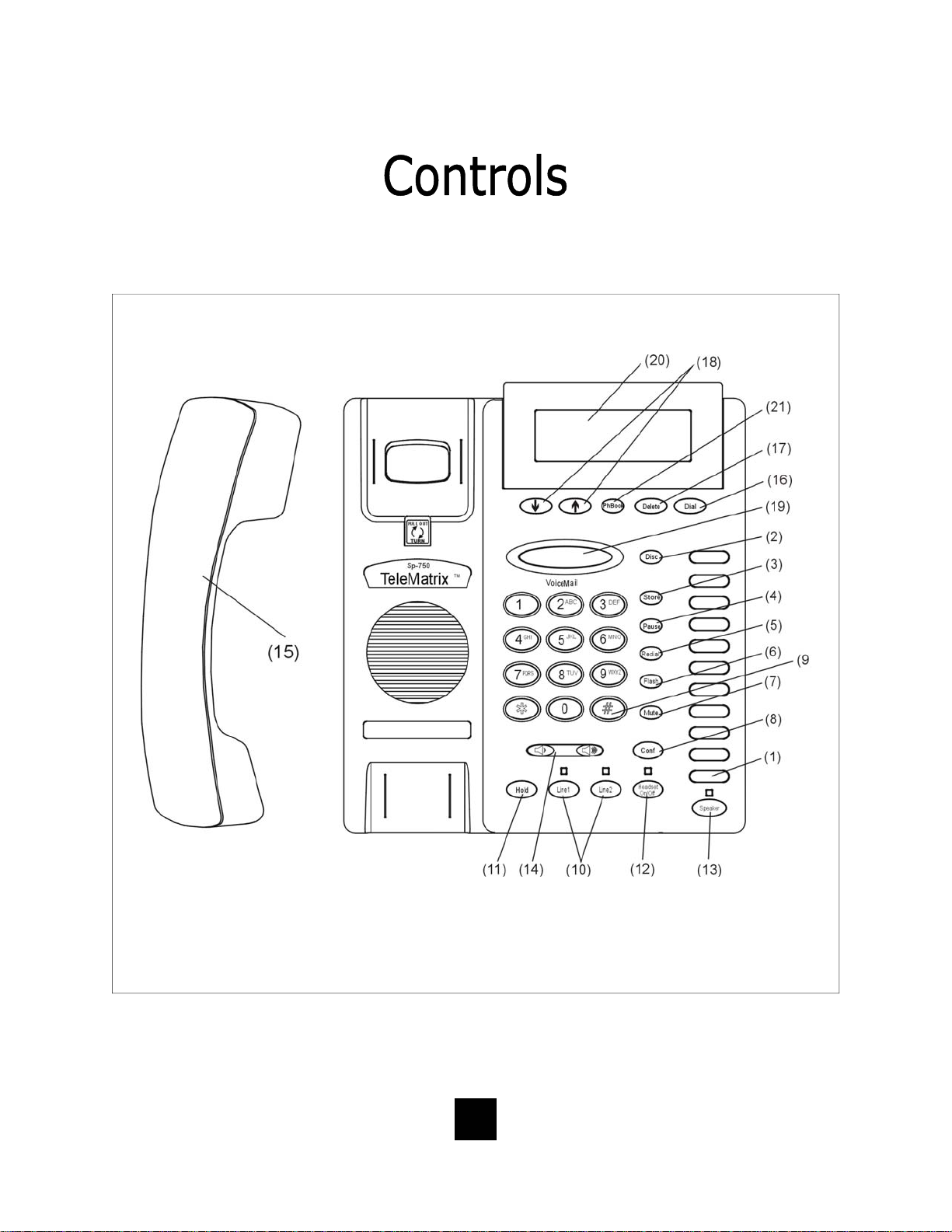
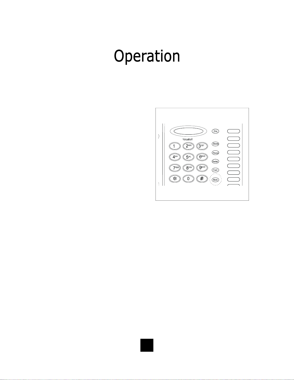
TOP PANEL
6
Page 7

1. Speed Dial Feature Keys……………..…. Eleven (11) one-touch keys used for speed dialing.
2. Disconnect Key ……………………...…….. Used to disconnect the line or place a new call.
3. Store Key……………………………….….…... Used to program user features.
4. Pause Key ...............................…. Used to place a timing delay when dialing.
5. Redial Key ......................……………. Redials the last number dialed.
6. Flash Key ..................……………..…. Provides a timed line break
7. Mute Key …………………………….………... Disables the handset and speaker phone microphones.
8. Conference Call Key……………………..… Used for conference calls.
9. Numeric Dial Pad ………………...………. Used for dialing.
10. Line 1 and Line 2 …………………….……. Used to select line 1 or line 2.
11. Hold Key ………………………………..…….. Lighted key used for placing callers on hold.
12. Headset ON/OFF Key ……………………. Lighted key used to turn the headset ON or OFF.
13. Speaker Key .………………................ Used to turn the speakerphone ON or OFF.
14. Volume Bar …………………..………………. Adjusts the loudness of the handset receiver, the head
set, and/or the speaker.
15. Handset ……………………………….……... Hearing-aid compatible handset.
16. Dial Key ..………................……....... Used to automatically dial the number displayed on the
LCD.
17. Delete Key ……………………………..……. Deletes stored Caller ID records and Phonebook
(PhBook) records.
18. Up and Down Scroll Key ..….......... Used to scroll Caller ID and Phonebook (PhBook)
records.
TM
19. Touchlite
Key...……………………....... Message Waiting Lamp (LED indicator) that blinks
to indicate a new message in the user’s voice mail
box (user must be subscribed to a messaging system).
20. LCD Display ...............……........... Large adjustable back-lit display that shows Caller ID,
number of calls received, date and time, and call log.
21. Phonebook (PhBook) Key ……………. Used to access names and numbers in the Phonebook
(PhBook) directory.
7
Page 8
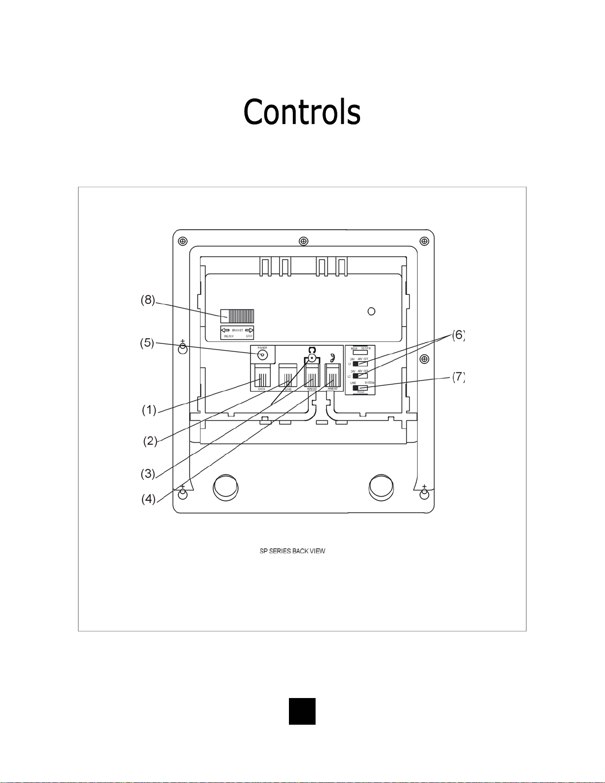
BOTTOM PANEL
8
Page 9

1 Data Port ..................................... Convenient port to connect a computer,
modem, fax or answering device.
2 Line Jack ………………………………………... Modular receptacle for connecting the
line cord.
3. Headset Jacks ............................. Convenient RJ port or 2.5mm coaxial port used
to connect an optional headset.
4 Handset Jack ............................... Connection for handset coil cord.
5. Power Adapter Receptacle ……..……… For optional coaxial power adapter.
6 Low Voltage MW Switch ………………… Used to select LED Message Waiting On or OFF.
7 Hold Key Switch ……………...…………… Used to select standard line hold or
programmable system hold.
8 Elevation Stand Lock ……………………… Used to “lock” the elevation stand.
9
Page 10
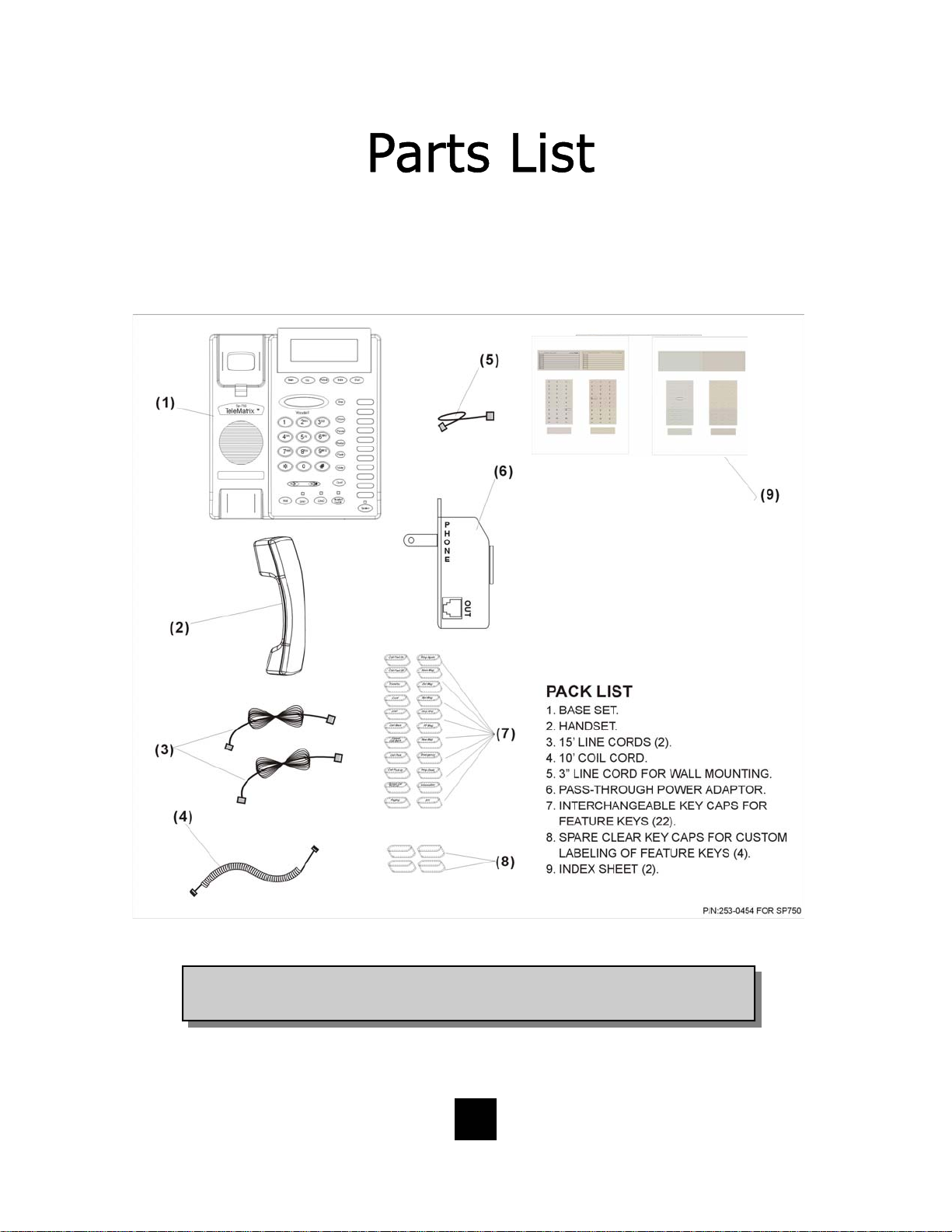
Parts Check List
The following parts are included with the Spectrum PLUS
TM
SP750:
NOTE: Spectrum PLUSTM Line Cords are 6-Pin 6-Conductor Line cords
(6P6C line cord). Replacement Line Cords must be same.
10
Page 11

Caution
• Never install telephone wiring during a lightning storm.
• Never in stall telephone jack s in wet locations unless the jack is
specifically designed for wet locations.
• Never touch uninstalled telephone wires or terminals unless the
telephone line has been disconnected at the network interface.
• Use ca ution when installing or modifying telephone lines.
Power Outlet Configuration
The Spectrum PLUS
outlet (60Hz).
TM
Series telephone requires external power from a standard 120V
IMPORTANT!
The telephone will not functio n if the line cord connections are not co rrect. Be sure that
the telephone line cord connections are not reversed (“LINE”/”PHONE”). Attach the line
!
cords to the power adapter and the wall before connecting to the telephone. Spectrum
TM
PLUS
Cords must be same.
Line Cords are 6-Pin 6-Conductor Line cords (6P6C line cord) . Replacement Line
11
Page 12
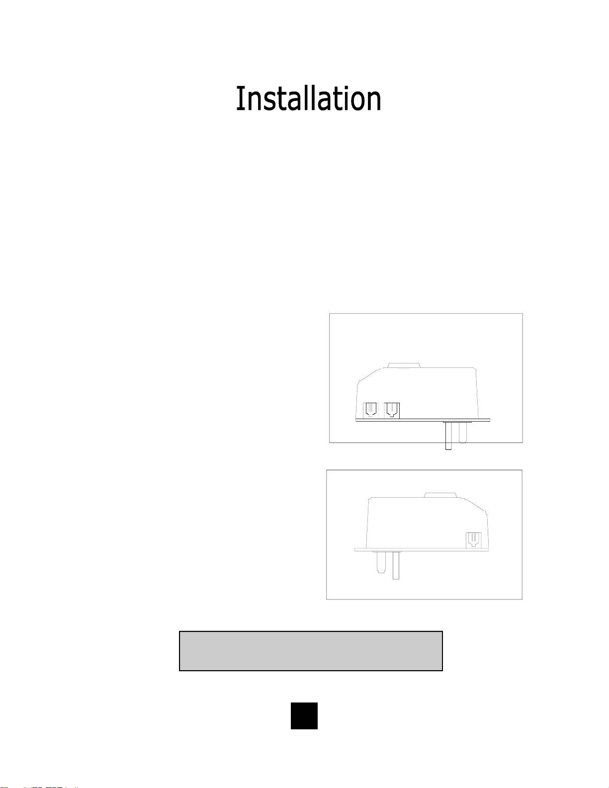
120V AC Outlet Recovery Power Adapter (provided)
The 120 VOLT AC OUTLET RECOVERY POWER ADAPTER is an featured TeleMatrix
product. It provides both the telephone lines and the power source in one cable
(6P6C line cord) and is designed to recover the use of the power outlet.
Connector Configuration
The 120 Volt Outlet Recovery Power Adapter has two (2) modular jacks. One
jack is labeled “LINE” and the other jack is labeled “PHONE”. These jacks allow
for a fully modular ins tallation.
Power Adapter “LINE” Connection
The power adapter “LINE” connection is
used to connect the telephone line from
the wall jack to the power adapter.
Using one of the 15-foot modular
telephone li ne cords, connect one end of
the cord to the RJ14 telephone jack on
L2L1 +L2
NEL
_
the wall or base board. The remaining
end of the cord plugs into the “LINE” side
of the power adapter.
Power Adapter “PHONE” Connection
The power adapter “PHONE” connection
is used to provide both the telephone
lines and the power source to the
telephone. Using one of the 15-foot
modular telephone line cords, plug one
end of the line cord into the back of the
telephone. Plug the remaining end to
the power adapter jack labeled
“PHONE”.
Troubleshooting Note: If there is no power to the telephone
after connecting the line cords, c heck to see if the line cords
are inserted on the opposite sides of the adapter.
12
OUT
EHNOP
Page 13
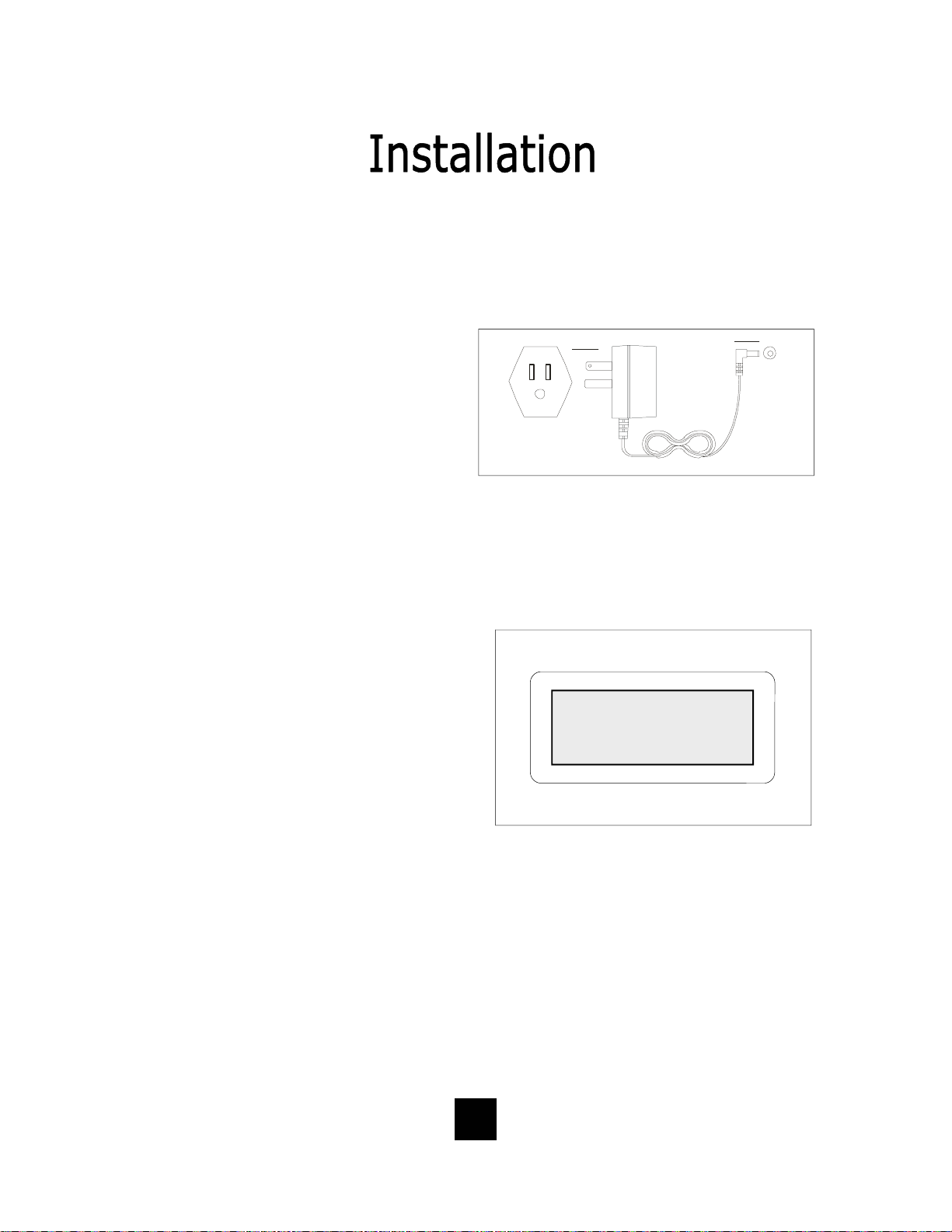
Installing The Wall Power Adapter
(Optional Component)
This compon ent i s b est used wh en wall
mounting the telephone. To install,
simply plug the power adapter into a
standard 120V AC power outlet. A
mounting hole is provided to secure
120V AC POWER
the power pack to the AC wall outlet.
Plug the AC power pack directly into
the wall outlet and then plug the coaxial connector into the receptacle
marked “POWER” located on the back
of the telephone.
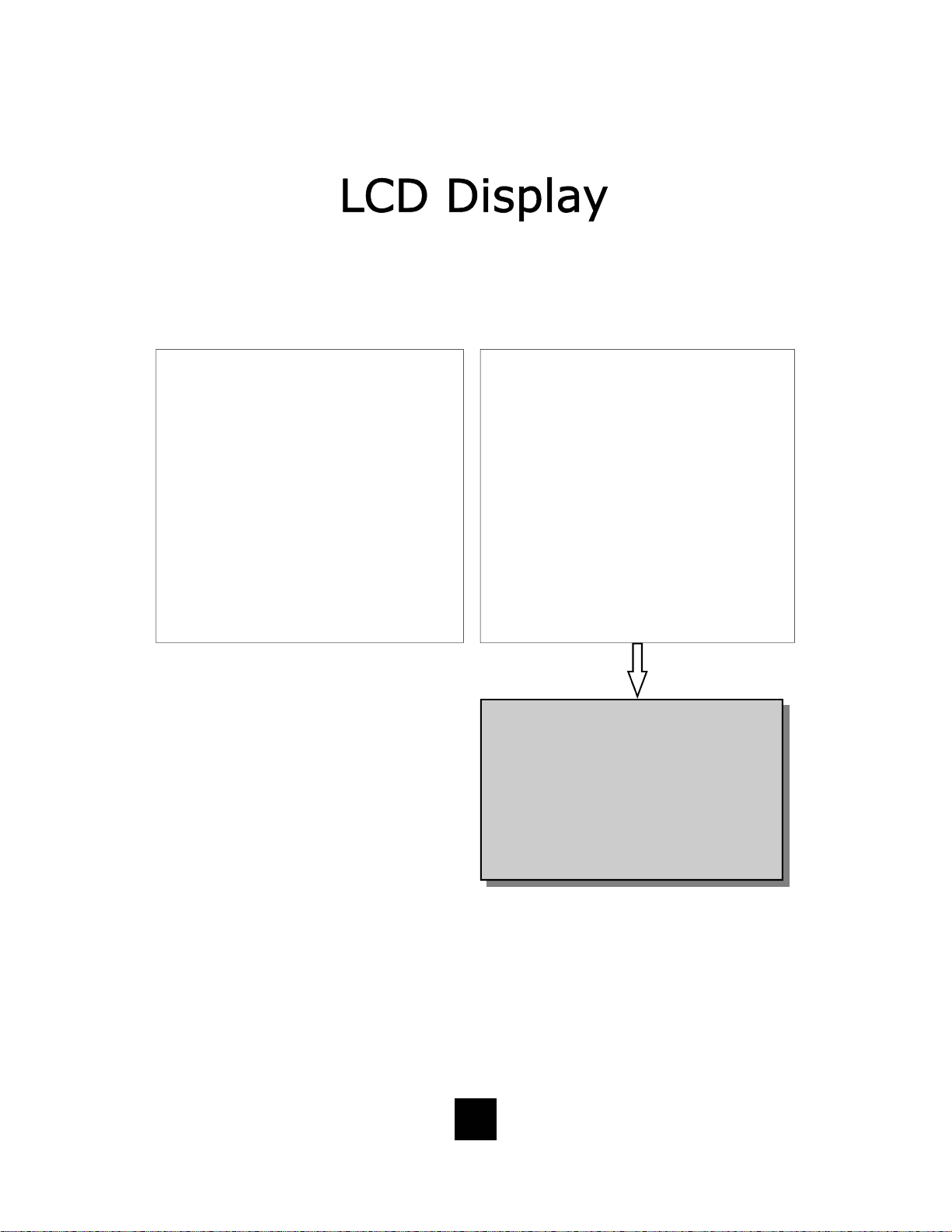
Comple ting the Power Insta l lation
If the installation is correct, the
information shown at the right will be
displayed on the LCD.
If the LCD does not display words and
numbe rs , c he ck y our p ow er
connections.
POWER
ORDER SEPERATELY
02/27 pm12:26
-00- -00-
NEW TOTAL
13
Page 14

Connecting the Handset Cord
A 10-foot modular coil handset cord is
provided. (Be sure that the wall/desk
elevation stand has not been attached).
To install the cord, simply plug the
short end of the handset cord into the
modular jack on the handset. The long
end of the handset cord plugs into the
jack labeled “Handset” located on the
bottom of the Spectrum PLUS
TM
base
unit. Place t he line cord into the ha ndset coil cord channel located directly
below the jack.
Installing the Keycaps
Twenty-two (22) preprinted named
feature keycaps are provided to identify
the speed dial key.
There are eleven (11) clear keycaps
already installed. To install preprinted
keys, remove the clear keycap by
simply pulling up. Replace with the
preprinted keycaps or place hand
written paper index sheets under a
clear keycap. P rogram each speed dial
key for the specific function of the key.
CLEAR "SNAP-ON" KEY CAP
OR SILK SCREEN KEY CAP
PLASTIC TOP CAB INET
Handset Cord
PLASTIC TOP CABINET
PLASTIC KEY TOP
NOTE: For speed dial programming instructions,
see the sect ion on “Pro gramming Proc edure For
Spectrum PLUS
manual.
tm
Speed Dial Features” in this
There are four (4) additional clear keycaps and two (2) index sheets provided as
spares. Use t hese for y our own pe rsonal speed d ial iden tities. Write th e speed di al
name on the blank speed dial index cards and insert into the blank keycaps. Place
the keycap on the correct memory speed dial location. (see index sheets provided
in box).
The twenty-two preprinted keycap names are below:
Call Fwd On Call Back Paging Skip Msg Information
Call Fwd Off Cancel Call Back Ring Again FF Msg 911
Transfer Call Park Save Msg Rew Msg
Conf Call Pick-up Del Msg Emergenc y
DND Group Call Pick-up Rpt Msg Help Desk
14
Page 15
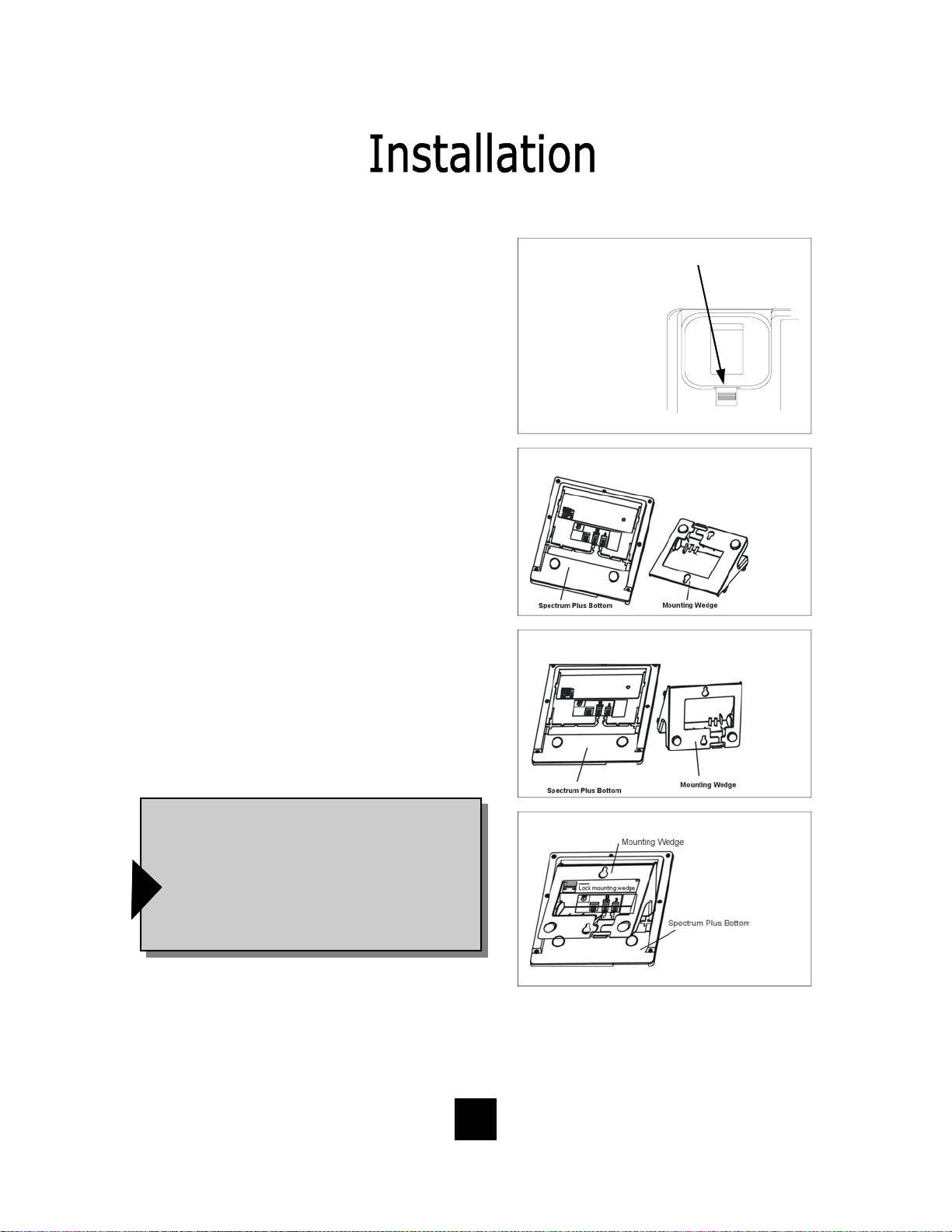
Wall Mounting the Spectrum PLUSTM Telephone
The Spectrum PLUSTM was designed to be
conveniently wall mounted without requiring
additional hardware.
Follow these easy steps:
1.The handset retaining clip must be in the correct
position to secure the handset into the handset
cradle. Engage the clip with your fingers and pull
the clip forward (towards you), rotate the clip 180º
and snap the clip back into place (figure 1). The
retaining clip cannot be removed.
1. UNSNAP
2. ROTATE 1 80 .
3. SNAP INTO PLA CE.
1.LIFT CLIP OUT WITH
FINGERS. IT CANNOT BE
REMOVED BECAUSE IT
IS SPRING LOADED.
2. ROTATE THE
0
CLIP 180
AND
IT WILL SMAP
BACK INTO THE OPPOSITE POSITION. AN
RETAINER CLIP
NOTE: CLIP IS
figure 1
2. The Spectrum PLUSTM has provisions for a
mounting wedge that must be correctly positioned.
This wedge allows the telephone to be viewed at a
correct angle when the phone is wall mounted.
Remove the wedge from the ph one base (figure 2).
3. Secure the line cord, coil cord and any wiring in
place prior to installing the wall mount wedge. The
wall mount base has extra large wiring channels
and strain relief poles for containing the wires in a
neat and orderly way. Wrap the wires around the
strain relief poles and then secure the wires
through the channel.
4. To wall mount, place the narrow edge at the top
edge of the phone base and slide the wedge upward into place (figure 3).
5. Lock the wall mount into position by sliding the
locking button to the r ight (figure 4).
Note: A 6-inch line cord is provided for when
the telephone is to be wall mounted. Connect
one end of the line cord to the phone jack and
the other end to the wall jack. Be sure to connect the power cord and line cords before plac-
ing mounting wedge on the bottom base. An
!
optional coaxial power supply can be used in
place of the supplied power supply. See your
local distributor for information.
Replace Mounting Wedge
figure 2
Replace Mounting Wedge
figure3
Lock Mounting Wedge
figure 4
Desk Mounting
To install the wedge for desk mounting, be sure the lock mechanism is positioned to the left
clear of the locking arm. Place the wedge in the slots, wide end toward top of phone base
unit, and slide the wedge upward into position. Lock the wedge into place.
15
Page 16

Message Waiting Light Indicator
The Spectrum PLUS
TM
telephone has a
Message Waiting Light Indicator
Message Waiting (MW) Light Indicator (figure
1). The indicator will blink to indicate that a
new message is in the user’s voice mailbox.
The Spectrum PLUS
TM
supports the following
telephone or PBX supplied message waiting
signals:
1. Telephone Company VMWI Service* (FSK
signal compatible, subscription to local
telephone company is required).
2. Or, Audible Stutter Dial Tone (SDT) signals
provided by local telephone company.
3. Or, 90-Volt NEON message waiting light
indicator signal provided by a PBX.
4. Low Voltage LED m essage waiting light in-
dicator light signal is provided by a PBX
The PBX system or telephone servi ce provider
has to activate the voice mail feature for the
!
light to illuminate and work properly. Be sure
that your telephone service provider or PBX
system has the compatible messaging service
available in your area or facility.
figure 1
NOTE: The Spectrum PLUS
telephone automatically reads the
Message Waiting (MW) signals
supplied by your service provider.
The LED signal supplied by a PBX
must have the LED Voltage switch
which is located on the bac k of the
telephone in the correct
position to operate the LED. See
the next page for instructions.
TM
Use this feature when alerting another that a saved message is in voice mail for that person or
use this feature when you simply want to turn the light off.
Be Aware: If there is a new incoming message and the telep ho ne company co ntinue s to s e nd
f
a new signal this light will re-activate. This will occur only when there is a new voice mail that
has not been heard.
How To Use: When on-hook, Press the “*” key for 3 to 5 seconds and the Message LED will
automatically turn on. At any time press “*” key for 3 to 5 seconds ,Message LED will turn off.
*Definition: VMWI is Visual Message Waiting Ind ication. This optio n requires a
d
subscription to your loc al telephone service provider for TouchLite
Feature Note: Message ON/OFF Notification.
TM
to activate.
16
Page 17

Low Voltage LED Switch
A low voltage LED switch is located on
the bottom of the phone. The switch
options are ON or OFF. The factory
default is OFF.
Line Voltage Switches
A voltage switch for each phone line is
located on the bottom of the phone.
The voltage options are 24 Volt, 48
Volt, or OFF. This voltage switch is
used to illuminate LED lamps on the
top side of the phone. It must be in
the correct voltage position to operate
the LED lamps. The factory default is
24 Volt.
System Hold Feature Option Switch
A feature switch for different hold
functions is located on the bottom of
the phone. The switch options are
standard “LINE Hold” or programmable
“System Hold”*.
The standard “Line Hold” allows for
normal hold function operation. The
programmable “System Hold”* feature
is used for optional PBX system
operations.
The switch default is set at the factory
as standard “LINE Hold”.
* Programming “System Hold” is an Administrator
function. To program System Hold, follow the
speed dial instructions in this manual. To store the
dialing pattern, press the HOLD key in place of the
memory location.
LOW VOLT MW
ON OFF
LOW VOLT MW
ON OFF
17
Page 18

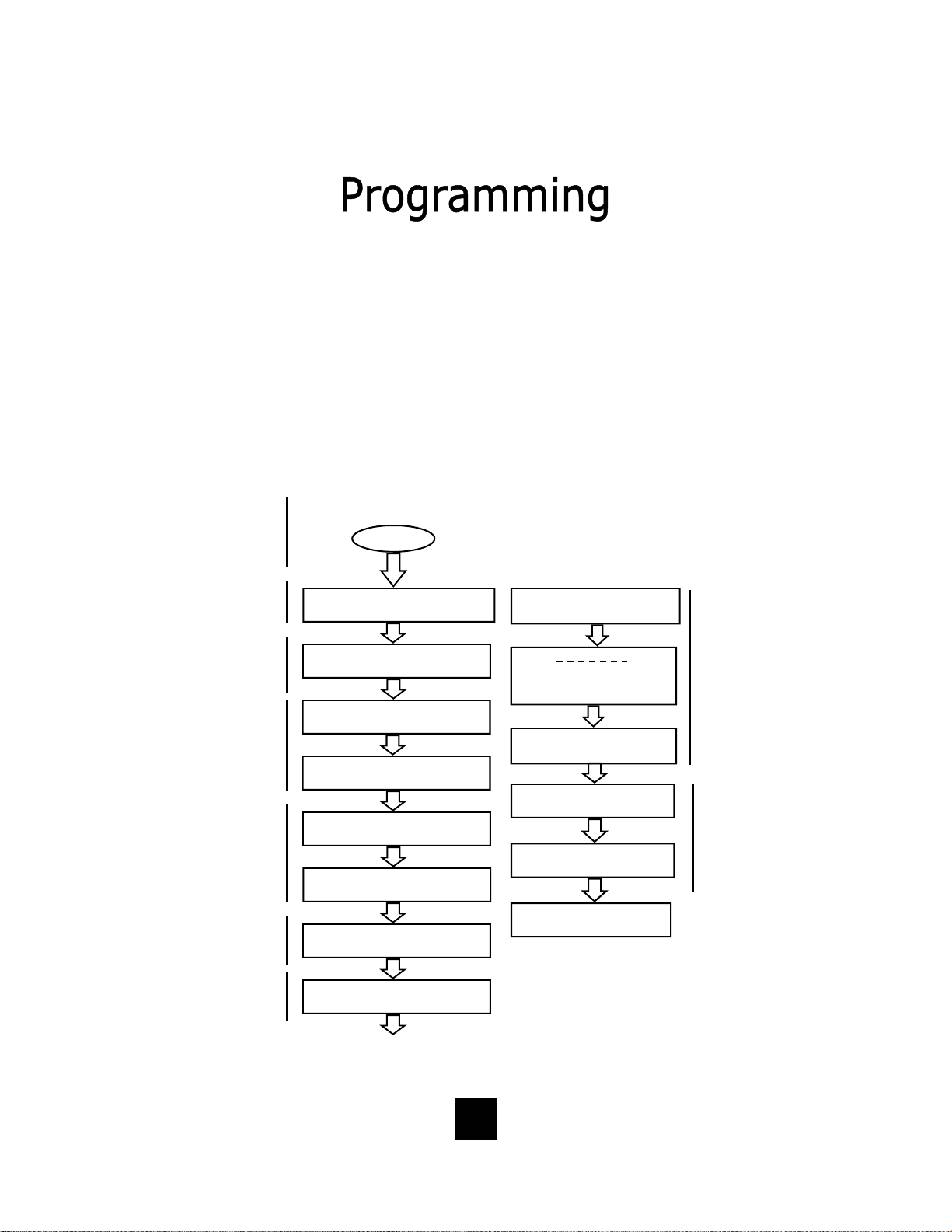
Programming Set Up Of the Spectrum PLUSTM Telephone
The Spectrum PLUSTM requires simple initial programming to set up the telephone.
One program mode is designed for Administrator set up and one program mode is for
User set up and use. Administrator programming features separate critical operating
set up information from the user telephone functions.
ENTER ACCESS NO. Set up pre-dialing number sequence, i.e. outside line.
ENTER AREA CODE Set up local area code to recognize local incoming calls.
LIVE DIALPAD
dialing, pressing dial key to activate.
Set up either using keypad dialing with automatic speaker activation, or using k ey pad
RESTRICT 1+ Long distance restriction. Restrict any outgoing number dialing that begins with a “1” .
FLASH TIME SET
Set up flash timing 100mS to 1000mS. Default 600mS.
PAUSE TIME SET Set up pause timing 1.0mS to 5.0mS. Default 3.6mS.
VOICE MAIL NO.
messages. PIN number characters will not be displayed.
Set up voice mail number. Add your PIN with seconds of wait time to get access to
CID RECORDS LOG SET Set up CID record log TOTAL or EACH.
18
Page 19
Programming Set Up Of the Spectrum PLUSTM Telephone
The Spectrum PLUSTM requires simple initia l progr amming to set up the telephone.
The program is designed for one Administrator and one or more users. Administrator
programming features separate critical operating set up information from the user
telephone functions.
The Administrator Quick Program Guide for the Spectrum PLUSTM Telephone
The Spectrum PLUSTM Quick Programming Guide is a sum mary list of set up options.
Additional detailed instru ctions are pro vided in the manual.
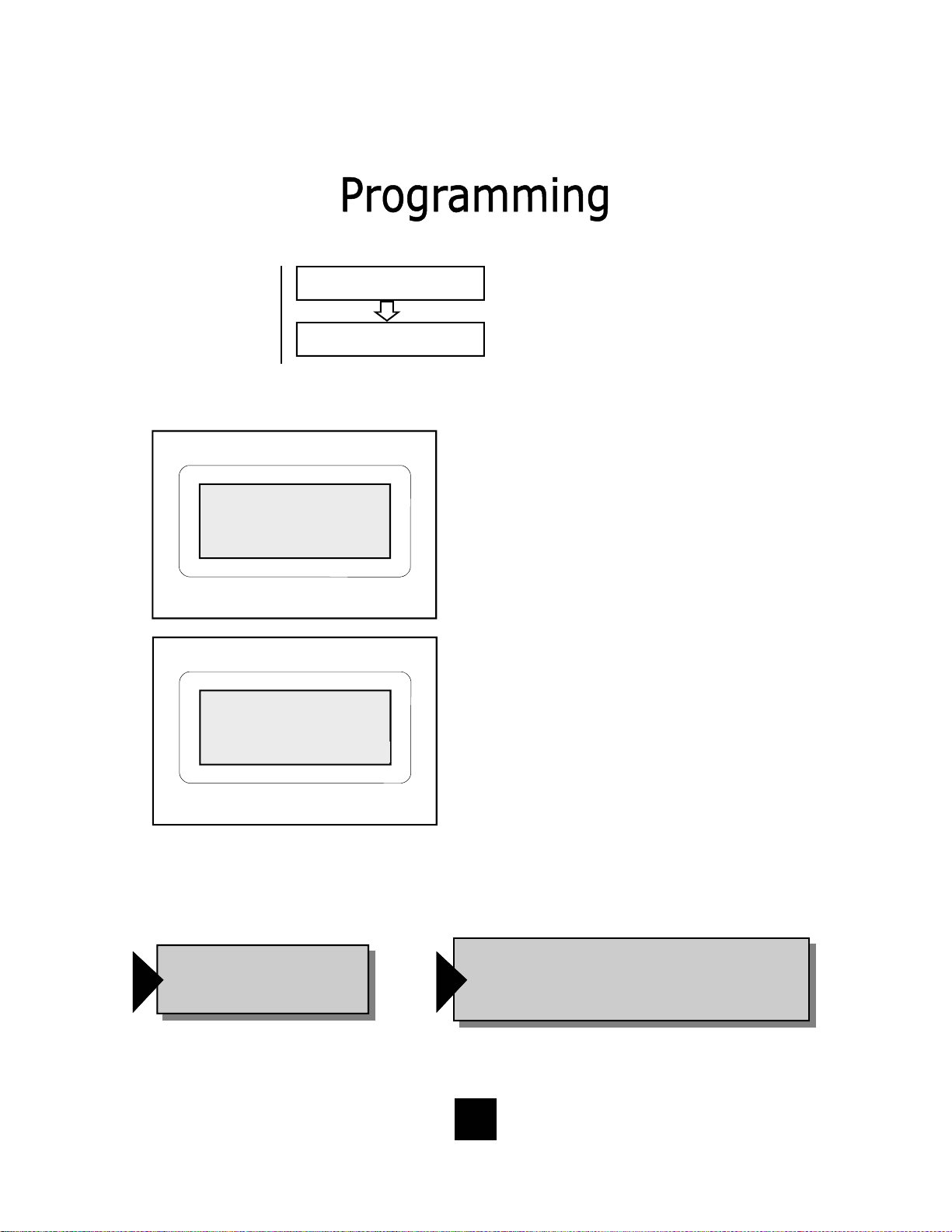
Programming is initiated
by holding down the
“STORE” key for six
seconds.
STORE
Set up pre-dialing number
sequence, i.e. outside
Set up local area code to
recognize local inco ming
calls.
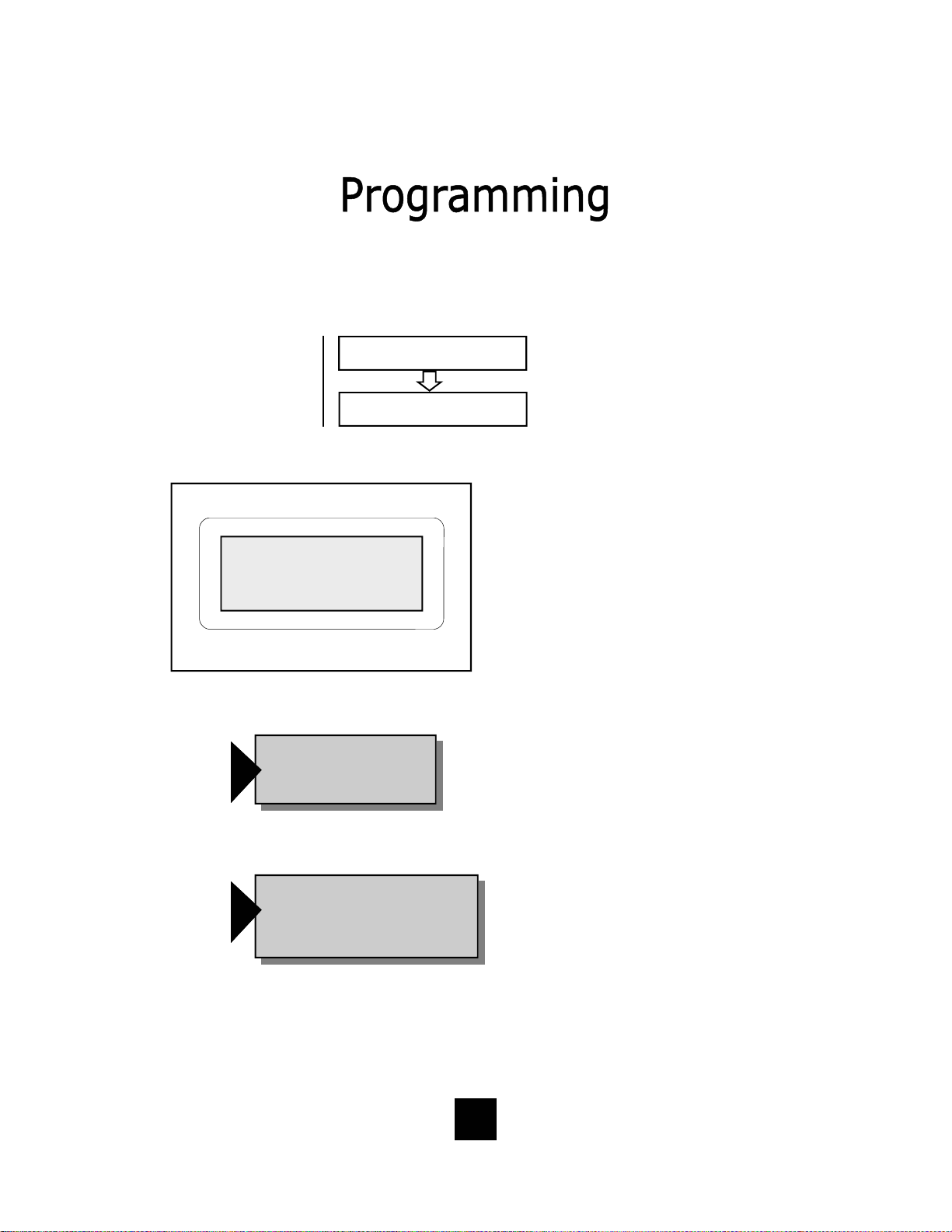
Set up either using keypad dialing with automatic
speaker activation, or
using key pad dialing,
pressing dial key to
activate.
Long distance restriction.
Restrict any outg o ing
number dialing that
begins with a “1” .
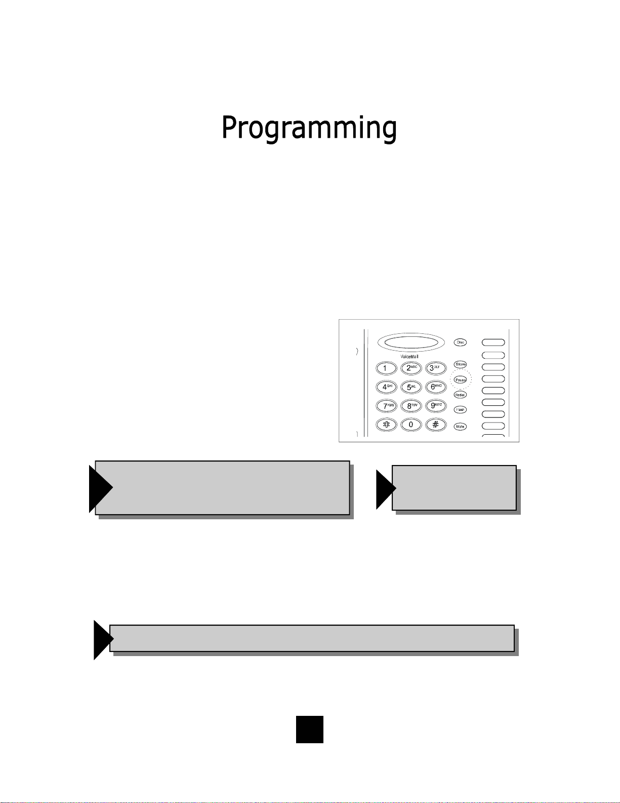
Set up flash timing
100mS to 1000mS.
Default 600mS.
Set up pause timing 1.0S
to 5.0S. Default 3.6S.
ENTER ACCESS NO.
ENTER AREA CODE
LIVE DIALPAD XXX
PRESS 1=ON 2= OFF
RESTRICT 1+
PRESS 1=YES 2= NO
FLASH TIME SET
PAUSE TIME x.x S
VOICE MAIL NO.
PIN NUMBER
SECOND OF WAIT?
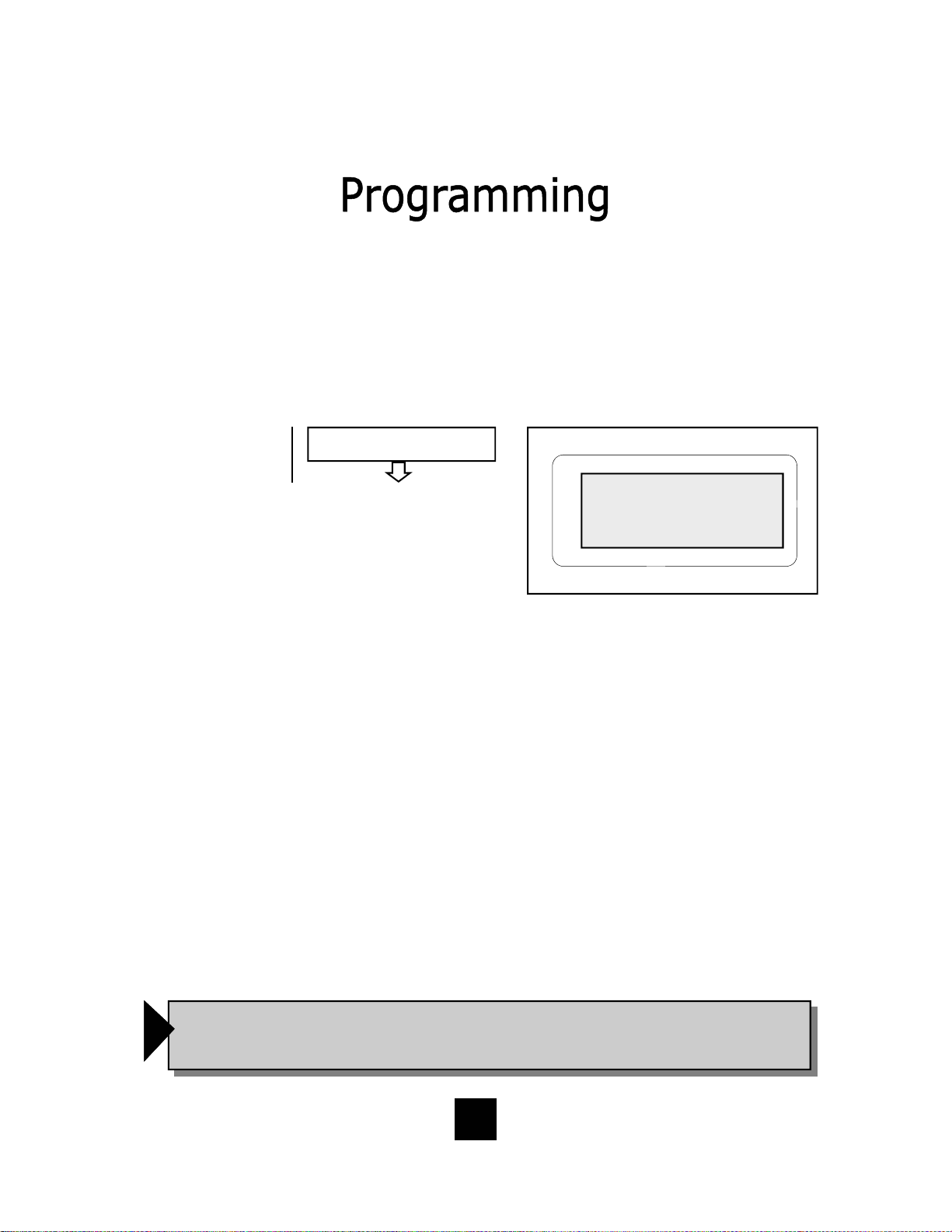
CID RECORDS LOG
1 = TOTAL 2 = EACH
ALL SETUP OK
Set up voic e ma i l n u mb e r. Ad d
your PIN with seconds of wait
time to get access to messages.
PIN number characters will not
be displayed on the LCD.
Set up the Caller Log record
display to s how sa me caller
separately logged or show
same caller in one line display
with number of incoming total
calls.
19
Page 20
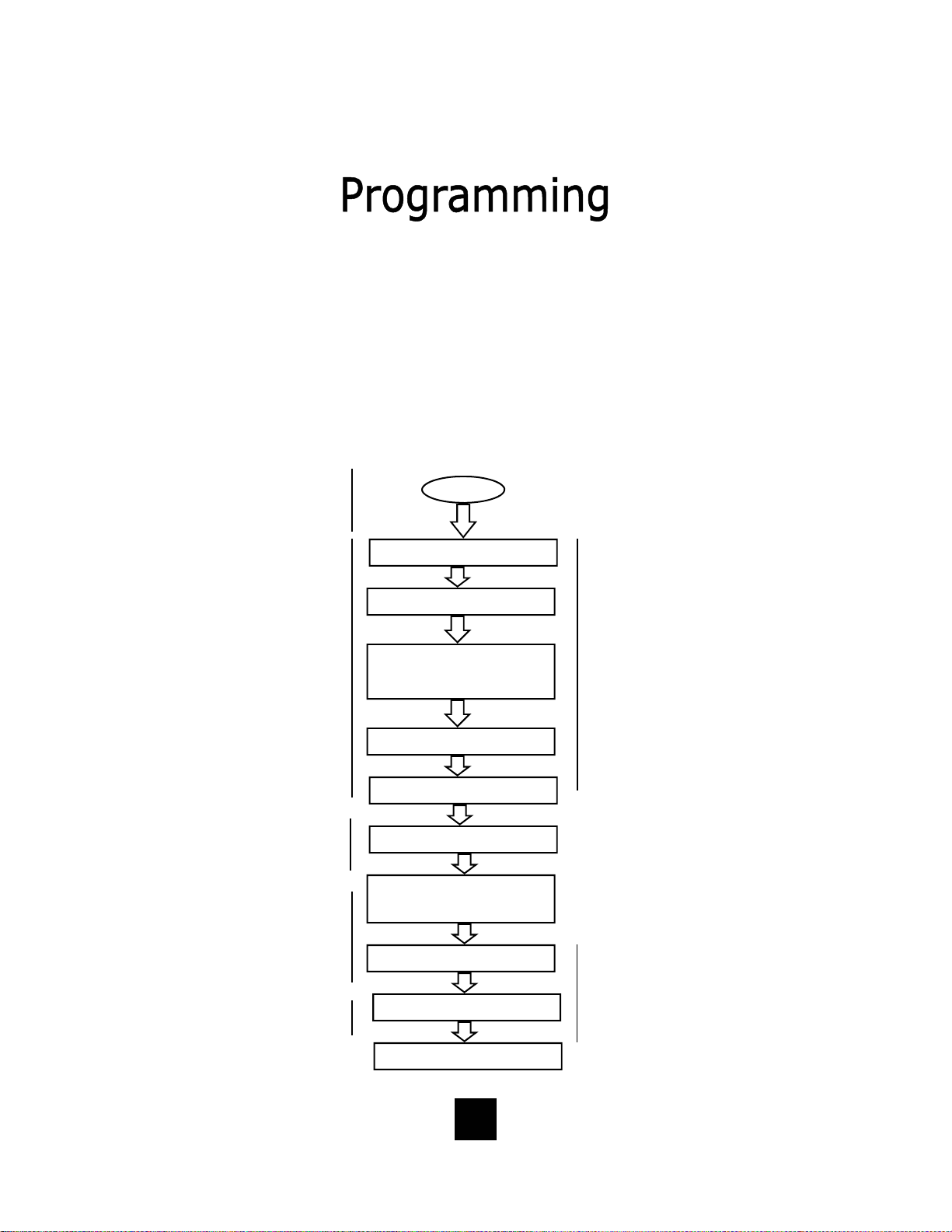
Administrator and User Set Up of the Spectrum PLUSTM Telephone
The Spectrum PLUSTM requires simple initia l progr amming to set up the telephone.
The program is designed for one Administrator and one or more users. Administrator programming features separate critical operating set up information from the
user telephone functions.
The Users Quick Program Guide for the Spectrum PLUSTM Telephone
The Spectrum PLUSTM Quick Programming Guide is a sum mary list of set up options.
Additional detailed instru ctions are pro vided in the manual.
Programming is initiated by quickly pressing the “STORE” key.
Set up date and time
Set up language
Set up ringing options of
ring tone (4 tones) and
ring volume (8 steps).
Press keypad numbe r
for sample of ringing
tone or volume.
Set up is complete.
STORE
SETUP MONTH:01
SETUP DAY:01
SETUP TI ME MODE
PRESS 1=12 2=24
AM=1 PM=2
SETUP HOUR:01
SETUP MINUTE:01
-1- -2- -3-
ENG FRA ESP
RING TONE 1- - 4
RING VOLUME 1- - 8
Note: the date and
time will automatically
set if your telephone
line is equipped with
Caller ID. The date and
time will be set by an
incoming ring.
Note: the software will
ask to select line 1 (L1)
or line 2 (L2). Each line
supports different tone
and volume settings.
ALL SETUP OK
20
Page 21
Set up using keypad
dialing with automatic
speaker activation or
using key pad dialing
and pressing dial key to
activate.
Display indicates condition of ON or OFF, then next screen appears.
12/01 PM 12:00
LIVE DIALPAD ON
12/01 PM 12:00
PRESS 1=ON 2=OFF
LIVE DIALPAD XXX
PRESS 1=ON 2= OFF
LIVE DIALPAD Feature
(Administrator)
This feature sets up the telephone dialing
pad method.
When LIVE DIALPAD is OFF, and the
handset is ON HOOK, the user enters a
number on the keypad and then must
press the “DIAL” key to activate dial
tone.
When LIVE DIALPAD is ON, and the
handset is ON HOOK, the dial tone activates immediately upon pressing the keypad.
The handset can be lifted at any time to
activate the receiver.
To enable or disable LIVE DIALPAD ON.
1. Press and hold the “STORE” key for
6-seconds.
2. Press “STORE” multiple times until
the LCD displays “LIVE DIALPAD ON”.
3. Press “1=ON” to enable, or “2=OFF”
to disable.
4. To exit the program mode, press
“DISC” or continue to the end of programming by pressing the “STORE”
key multiple times unti l the display
reads “All Setup OK”.
Note: Programming can
only be performed when
!
the phone is on-hook
NOTE: The Live Dial Pad feature works only
when the handset is ON HOOK, it does not
!
work when the handset is OFF HOOK.
21
Page 22
Long distance restriction.
Restrict any outg o ing
number dialing that begins with a “1” .
RESTRICT 1+
PRESS 1=ON 2= OFF
Restrict 1+ Feature
(Administrator)
This feature sets up a res t riction
when using long distance calling.
To enable RESTRICT 1+.
1. Press and hold the “STORE”
key for 6-seconds.
12/01 PM 12:00
RESTRICT: 1+
Note: Programming ca n only
be performed when phone is
!
on-hook.
Note: With 1+ Restrict Dialing, the
user cannot dial any number begin-
!
ning with a “1”.
2. Press “STORE” multiple times
until the LCD displays
“RESTRICT 1+”.
3. The display will read “ PRESS 1
= YES 2 = NO”.
4. To enable restriction, press “1”
on the keypad.
5. To disable restriction, press “2”
on the keypad.
6. To exit the program mode,
press “DISC” or continue to the
end of programming by pressing
the “STORE” key multiple times
until the display reads “All Setup
OK”.
22
Page 23

Programming Flash Timing into Memory
(Administrator)
Flash Timing can be programmed into the Spectrum PLUS
TM
speed dial memory.
This function allows for a timed line break in the sequence of the dialing patterns
when using the speed dial keys. This function may be required for accessing line
features provided by your telephone system or local telephone company. The
flash timing options are 100 through 1000 milliseconds, programmable in 100mS
increments.
Set up flash timing
100mS to 1000mS.
Default 600mS.
FLASH TIME SET
12/01 PM 12:00
600
FLASH TIME SET
Using A Flash When Dialing
To use a Flash when dialing, simply press the “FLASH” key at the appropriate
point in the number sequence being dialed from the key pad.
!
NOTE: Each “Flash” function counts as 1-digit when stored into a speed dial memory location
23
Page 24

Programming Flash Timing
(Administrator)
Flash timing can be programmed for different timing options listed below.
1. Press and hold the “STORE” key for 6-seconds to enter set up.
2. Press the “STORE” key multiple times until the LCD display reads “FLASH TIME
SET”.
3. Enter the flash timing to be stored into memory using the keypad by pressing
the following keys on the keypad in the order shown. The keypad entry will be
displayed on the LCD Screen.
For 100mS press "1" "0" "0" on the keypad.
For 200mS press "2" "0" "0" on the keypad.
For 300mS press "3" "0" "0" on the keypad.
For 400mS press "4" "0" "0" on the keypad.
For 500mS press "5" "0" "0" on the keypad.
For 600mS press "6" "0" "0" on the keypad.
Note: Programming can
only be performed when
!
the phone is on-hook
For 700mS press "7" "0" "0" on the keypad.
For 800mS press "8" "0" "0" on the keypad.
For 900mS press "9" "0" "0" on the keypad.
For 1000mS press "1" "0" "0" "0" on the keypad.
4. To exit the program mode, press “DISC” or continue to the end of program-
ming by pressing the “STORE” key m ultiple times until the display reads “All
Setup OK”.
5. To confirm the flash timing programmed in memory, repeat the Administrator
programming sequence to see flash timing display.
Programming Example for 100mS
Press “STORE” for 6 seconds, Press “STORE” again until LCD
reads “ “FLASH TIME SET”. Enter digit s “100” from the keypad .
Press “STORE” to enter the timing into memory.
!
NOTE: The Flash Timing factory default is 600mS
24
Page 25

Programming Pause Timing
(Administrator)
A Pause time between 1.0-seconds to 5.0-seconds can be programmed into memory. This function allows for a delayed timing for those systems requiring a different
time delay and allows the user to delay the dialing pattern of a number. This
function may be required for accessing line features provided by telephone provider
or local telephone company. A speed dial number may need to pause during its
dialing sequence to ensure proper connections.
Set up pause timing 1.0S
to 5.0S. Default 3.6S.
Pause timing can be programmed for different timing options listed below.
PAUSE TIME x.xS
12/01 PM 12:00
PAUSE TIME:3.6S
1. Press and hold the “STORE” key for 6 seconds to enter set up.
2. Press the “STORE” key multiple t imes until the LCD display reads “PAUSE
TIME:3.6S”.
3. Enter the pause timing to be stored into memory using the keypad by pressing
the following keys on the keypad in the order shown. The keypad entry will be
displayed on the LCD Screen.
Examples:
For 2.0-seconds press "2" "0" on the keypad.
For 2.1-seconds press "2" "1" on the keypad.
For 3.2-seconds press "3" "2" on the keypad.
For 4.9-seconds press "4" "9" on the keypad.
4. Press the “STORE” key to enter the new pause timing value.
5. To exit the program mode, press “DISC” or continue to the end of program-
ming by pressing the “STORE” key m ultiple times until the display reads “All
Setup OK”.
NOTE: If you require a pause time delay longer than the maximum setting of 5.0S,
!
stack the pauses within the dialing pattern to achieve the long e r timing.
25
Page 26
Programming a Pause into Speed Dial Memory
(Administrator)
Pause(s) can be programmed into the speed dial memory. This function puts a
delay the dialing pattern of a number when stored in memory. Multiple pauses
can be programmed into speed dial for added pause time.
To Program A Timed Pause
1. To store a Paus e in to Speed D ial memory,
simply press the “PAUSE” key in the
numbering sequence when programming
speed dial memory keys.
Also see Programming Speed Dialing in this manual.
NOTE: The default Pause timing is 3.6 Seconds.
!
A multiple of Pauses can be programmed
into speed dial memory to increase the delay.
Using a Pause when Dialing
To use a Pause when dialing, simply press the “PAUSE” key at the appropriate
point in the number sequence being dialed from the key pad.
NOTE: Each “Pause” function counts as 1-digit when stored into a speed dial memory location..
!
Note: Programming can
only be performed when
!
the phone is on-hook
26
Page 27

Programming the Access Number into Memory
(Administrator)
In some cases, a digit or digits are required to access an outside line (i. e. 9) . The
Access Number can be programmed into the phone. This function allows the user
to automatically dial number(s) that are required prior to dialing the displayed
number.
• The number to be programmed is based on your specific area dialing require-
ments and may not be required.
• This option is not mandatory for the proper operation of the Caller ID display.
Set up pre-dialing number sequence, i.e. outside
line.
Note: Programming can
only be performed when
!
phone is on-hook
ENTER ACCESS NO
12/01 PM 12:00
9 - - - -
ENTER ACCESS NO.
To Set Up The Access Number
1. Press and hold the “STORE” key for six seconds to enter programming.
2. Press “STORE” until the LCD display reads “ENTER ACCESS NUMBER”.
3. Enter the desired number, for example, a “9”.
4. Press the “STORE” key to enter the number into memory.
NOTE: There is no need to enter PAUSE. The Call Back operation
!
automatically inserts a pause after the Access Code Number.
To Delete The Access Code
1. Press and hold the “STORE” key for six seconds to enter programming.
2. Press the “STORE” key until the LCD display reads “ENTER ACCESS NUMBER”.
3. Press the “DELETE” key.
4. Press the “STORE” key again to continue.
27
Page 28
Programming the Area Code into Memory
(Administrator)
An Area Code can be programmed into the phone me mory . The Area Code is programmed into memory to allow the phone to recognize the local area code. When
this number is programmed, the Area Code WILL NOT be dialed when calling
back a number within the same local calling area.
Set up local area code
to recognize local
incoming calls.
ENTER AREA CODE
12/01 PM 12:00
719 - -
ENTER AREA CODE
Programming the Area Code into Memory
1. Press and hold the “STORE” key for 6-seconds to enter programming.
2. Press the “STORE” key multiple t imes until “ENTER AREA CODE” is displayed.
3. Enter the area code number of the local area code using the numeric dial pad.
4. Press the “STORE” key to store the area code into memory.
5. To exit the program mode, press “DISC” or continue to the end of programming
by pressing the “STORE” key multiple times un til the display reads “All Setup
OK”.
In some areas, the Area Code is required when placing a Local Call
In some areas, the local service provider will use the same area code for local calls. The
following options are available.
Try each of the following scenarios and use the one with the best result.
1. Program the Area Code first, then place a local test call.
2. Delete the area code and do not program the Access Code. Place a local test call.
3. Program the Area Code into the Access Code location. Place a local test call.
4. Use the keypad to add additional numbers to the displayed number on the screen.
Place a local test call.
NOTE: Depending on you r area and dialing pattern, you ma y obtain the best result
!
by using both the access code and area code fiel ds . If these sequences do not work,
use the keypad entry as an option for your Call Back.
28
Page 29

Programming Voice Mai l
(Administrator)
Voice Mail (VM) access numbers and their associated “Personal Identification
Number” (PIN) can be programmed into phone memory when Voice Mail is activated. The feature allows the user to automatically obtain their voice mail using
the Spectrum PLUS
TM
TouchLiteR speed dial key.
VOICE MAIL NO.
PIN NUMBER
SECOND OF WAIT?
Note: Programming can
only be performed when
!
phone is on-hook
Add the Voice Mail
number to dial. Add
users PIN. Add seconds of wait time to
delay access until
Telco introduction
message is complete.
Note: PIN characters
will not be displayed
on the LCD.
12/01 PM
5551212
VOICE MAIL NO.
12/01 PM
- - - - - - - -
PIN NUMBER
12/01 PM
05
SECOND OF WAIT?
29
Page 30

Programming Voice Mai l
(Administrator)
To program the Spectrum PLUS
TM
one touch “MESSAGE WAITING” speed dial
key, follow these programming instructions.
Programming Voice Mai l D ialing
1. Press and hold the “STORE” key for 6seconds to activate Administrator mode.
2. Press the “STORE” key multiple times
until “VOICE MAIL NO.” is displayed on
the LCD screen.
3. Enter the voice mail number. The area
code is not required if AREA CODE is programmed into memory.
4. Press the “STORE” key to store the voice
mail number into the VOICE MAIL memory key.
5. Enter the “PIN NUMBER”, up to 8-digits.
The PIN characters will not be displayed.
6. Enter the “SECONDS OF WAIT?”, up to 99
seconds.
7. To exit the prog ram mod e, press “DISC”
or continue to the end of programming by
pressing the “STORE” key multiple times
until the display reads “All Setup OK”.
After programming voice mail, test the program by
placing a voice mail into the voice mail messaging
system. Wait for the Voice Mail button to illuminate.
Then, press the key located on the base unit (when in
OFF HOOK position) and it will dial the pre-programmed
numbering sequence. The “SECONDS OF WAIT” may
need to be increased if the voice mail was not retrieved
Note: This feature must be turned on by your local
service provider.
Test the program
.
12/01 PM 12:00
555-1212
VOICE MAIL NO.
12/01 PM 12:00
- - - - - - - -
PIN NUMBER
12/01 PM 12:00
05
SECOND OF WAIT?
30
Page 31

Programming Procedure for Spectrum PLUSTM Speed Dial Features
(Administrator) (Manual Entry of Characters)
The Spectrum PLUSTM Telephone has eleven (11) one-touch speed dial locations that
are convenient for dialing frequently used telephone numbers. This feature is under
Administrative control so user changes do not occur.
• Speed dial programming must be done with the telephone plugged into the telephone line and power adapter.
• Programming can be performed with the telephone on-hook only.
• A maximum of 32-digits can be entered into ENTER NUMBER and 32-characters into ENTER NAME.
ENTER NUMBER
ENTER NAME
Set up speed dial memory locations with name
and number entries.
Check verifies correct
entry.
To Progra m Speed Dial Locations
1. Press and hold the “STORE” key quickly.
The words “SET UP MONTH: 01” will appear
(figure 1).
2. Next, press the speed dial location key
where the desired location will be. The
display will read “Mxx NO CONTENT”. If the
display shows a record, then there is a
stored name and number in that location
(figure 2).
3. Press the “STORE” key again and the dis-
play will read “ENTER NUMBER” (figure 3).
4. Using the dial pad, enter the number. Note
that the local area code is not required if
AREA CODE is pre-programmed into memory.
5. After entering the number, press the
“STORE” key. The displ ay will read “ENTER
NAME” (figure 4).
6. Using the keypad, enter the name associated
with the number being programmed and include the Flash, and/or Pause, when needed.
7. Press the “STORE” key to store the entry.
8. Program other sp eed d ial locati ons, repeat 2
to 7.
9. To exit the program mode, press “DISC”.
12/01 PM
SET UP MONTH: 01
Figure 1
12/01 PM
M01 NO CONTENT
Figure 2
12/01 PM
ENTER NUMBER
Figure 3
12/01 PM
ENTER NAME
31
Figure 4
Page 32

To Verify Speed Dial Programming
(Administrator)
The contents of each speed dial location can be verified or “checked” while the
Spectrum PLUS
TM
unit is in the programming mode.
• Memory verification is accomplished w ith the Spec tr um PLUS
TM
on-hook.
To Verify Speed Dial Locations
1. Press and hold the “STORE” key quickly. The words “SET UP MONTH: 01”
will appear (figure 1).
2. Next, press the speed dial location key to verify. The display will show the
memory location, the name, and the number in memory.
3. To check other memory locations, simply press other speed dial locations.
4. To exit the program mode, press “DISC”.
Note: Programming can
only be performed when
!
phone is on-hook
NOTE: Blank index card sheets are provided for
convenience. Complete and plac e the index
!
card into the speed dial memory key.
NOTE: A Caller ID record cannot be stored into the speed dial key memory
location. Entries c a n only be made manually by the Adminis tra tor programming
!
feature. This is for purposes of security and standardization of speed dial
locations.
32
Page 33

Phonebook Programming
(Manual Programming of Records)
The Spectrum PLUSTM Telephone Phonebook Feature allows for 100 name and number
records for frequently dialed calls. This section describes the Phonebook programming.
• Programming must be done with the power adapter plugged into the wall.
• Programming can only be performed with the telephone on-hook.
• A maximum of 32-digits can be entered into ENTER NUMBER and 12-characters into ENTER NAME.
ENTER NUMBER
ENTER NAME
Set up speed dial memory locations w ith na me
and number entries.
Check verifies correct
entry.
To Program a Phonebook Record Manually
1. Press the “STORE” key quickly. The words
“SETUP MONTH:01” will appear (figure 1).
2. Press the “PHONEBOOK” key. The words “ENTER
NUMBER.” will appear ( figure 2).
3. Next, press the numbers on the dial pad to enter
the number pattern to be stored. It is
recommended to enter the local area code in the
numbering sequence. Local area code dialing will
not occur when the AREA CODE is programmed
into setup. Using the keypad, enter the name associated with the number being programmed and
include the Flash, and/ or Pause, when needed.
4. Press the “STORE” key again and the display will
read “ENTER NAME” (figu re 3).
5. Using the dial pad, enter the name of the person
to be stored. See the chart on the next page for
character entries.
6. After entering the name, press the “STORE” key.
The display will read “PLEASE WAIT” (figure 4).
The memory function is now storing the entry. If
the record is already in memory, the display will
read “REPEAT PHBOOK”.
7. To store another record manually, repeat line item
1 through 6. .
8. To exit the program mode without saving, press
the “DISC” key.
12/01 PM 12:00
SETUP MONTH:01
Figure 1
12/01 PM 12:00
ENTER NUMBER
Figure 2
12/01 PM 12:00
ENTER NAME
Figure 3
12/01 PM 12:00
PLEASE WAIT
33
Figure 4
Page 34

Phonebook Programming
(Automatic Programming of Records)
The Spectrum PLUS
TM
Telephone Phonebook Feature allows for 100 name and number records for frequently dialed calls. This section describes the Phonebook programming using existing Caller ID records that are in the Caller ID record storage.
• Programming must be done with the power adapter plugged into the wall.
• Programming can be performed with the telephone on-ho ok .
• A maximum of 32-digits can be entered into ENTER NUMBER and 12-characters into ENTER NAME.
• You must be subscribed to a telephone service providers Message Waiting System to receive Caller ID
records.
Transferring Caller Log Records into Phonebook Memory
1. Be sure the LCD d ispl ay is in the begi nning p ositio n and no fe ature is in us e.
A call record must be store d into the caller log prior to u s ing this feature.
2. P r ess the “UP” or “DOWN” key to locate the incoming caller name and
number from the caller log.
3. To activate EDIT MODE, press any key on the keypad. Use the “DELETE”
key to delete a digit or use the k eypad to add a digit.
4. P r ess the “PhBook” key to store the number. The LCD will display “PLEASE
WAIT” and will add the record into memory. If the record is already in
memory, the display will read “REPEAT PHBOOK”.
5. P r es s “DISC” to exit or “STORE” to continue programming.
34
Page 35

Manual Entry From Keypad (Guide)
Use the following chart to add characters when programming into memory.
Press
Keypad:
Key 1
Key 2
Key 3
Key 4
Key 5
Key 6
Key 7
Key 8
Key 9
Key 0
Key *
Key #
Once Twice
1
A B C 2
D E F 3
G H I 4
J K L 5
M N O 6
P Q R S 7
T U V 8
W X Y Z 9
0
adds space *
. ( )
=
: —
Three
Times
Four
Times
Five
Times
Six
Times
#
35
Page 36

Headset Feature
The Spectrum PLUS
separate port for plugging in an optional
headset. The port is located on the bottom of the base unit. The TeleMatrix
FreeSpeech
TM
TeleMatrix feature that allows the user the
freedom to “t oggle” bet ween th e headset,
handset and speakerphone modes during
a conversation.
When the “HEADSET ON/OFF” key is
ON, pressing t he “SPEAKER” key will ac-
tivate the speaker and disconnect the
headset line automatically. This feature
avoids having to use the hookswitch/
handset to process telephone calls while
in headset mo de.
The headset can be purchased from a
TeleMatrix distributor. There are many
varieties of headset models available.
TM
is equipped with a
Talk Feature is a unique
!
NOTE: An external amplifier is NOT
recommended. The phone has a built
in amplifier.
Installing a Headset
The headset port is located on the bottom
side of the telephone base.
Plug the modular end of the headset cord
into the modular port of the telephone
labeled “HEADSET” (figure 1).
Press the “HEADSET ON/OFF” key to
activate the headset. The LED above the
key will illuminate to indicate that the
headset is on (figure 2 ).
36
Figure 1
Figure 2
Page 37

Using A Headset
The “HEADSET ON/OFF” key controls the activation of the Headset. When using the
headset feature, the handset remains on-hook at all times.
Placing/Answering a Call
using the Headset On/Off Feature
• To answer an incoming call, press the “HEADSET ON/OFF” key to activate the head-
set. The LED above the “HEADSET ON/OFF” key will be illuminated when in ON position.
• Adjust the volume, if necessary.
• Use the features of the headset that are available with the handset in use.
• You can dial using the the keypad or a speed dial key.
• To end headset activation, press the “HEADSET ON/OFF” key. The LED above the
“HEADSET ON/OFF” key will turn off.
Volume Lock Feature — When the handset, speaker, or headset
volume feature is selected, the volume will automatically stay at
f
that setting in the next use.
FreeSpeechTM Talk Feature is a unique TeleMatrix feature that
allows the user the freedom to “toggle” between the headset,
f
handset and speakerphone modes during a conversation.
Autoline Select Feature — F or 2 li ne phone s, when a ctivati ng
the handset, speaker, or headset for dialing, the phone will auto-
f
matically select the open line. The first line for auto selection is
Line 1, then Line 2.
37
Page 38

Caller Identificati on (Caller ID*) LCD Display
Type II Caller ID Te ch nology
The Spectrum PLUSTM LCD display supports
Type II Caller ID*. This type of Caller ID
displays the identity of a second incoming
call while the user is actively on a first
incoming call. The user has the option to
answer the call or allow the call to automatically be forwarded to voice mail*.
LCD Backlighting
The Spectrum PLUSTM is equipped with a
backlit Liquid Crystal Display (LCD) that displays Caller ID information. The LCD displays:
• Caller’s Name and Number
• Call Log Information
• Message Waiting Envelope
• Time & Date
• Line In-Use
*NOTE: The Caller ID feature and
Voice Mail will ONLY oper ate if you
subscribe to your local telephone
company and/or if your PBX
telephone system is equipped with
this technology. These telephone
!
features will not work unless you
are a subscriber.
If you are uncertain whether your
PBX telephone system can transfer
Caller ID data, contact your
telephone service provider or your
PBX Service Company.
NOTE: The LCD display backlighting
feature is activated after receipt of the
first ring or with in-use operation of the
handset, headset activation or speaker-
!
phone (incoming and outgoing calls).
The illumination is active during the call
and will shut off nearing 30 seconds
after disconnecting.
Display Information Management Keys
The Spectrum PLUS
tion displayed on th e Liquid Crystal Display (LCD). This includes:
TM
is equipped with five management keys supporting the informa-
• Phone Book Management
• Caller ID Log Record Management
• Entering of Names and Numbers
• Editing of Names, Numbers
• Scrolling and One Touch Dialing Capabilitie s
38
Dial Delete PhBook
Page 39
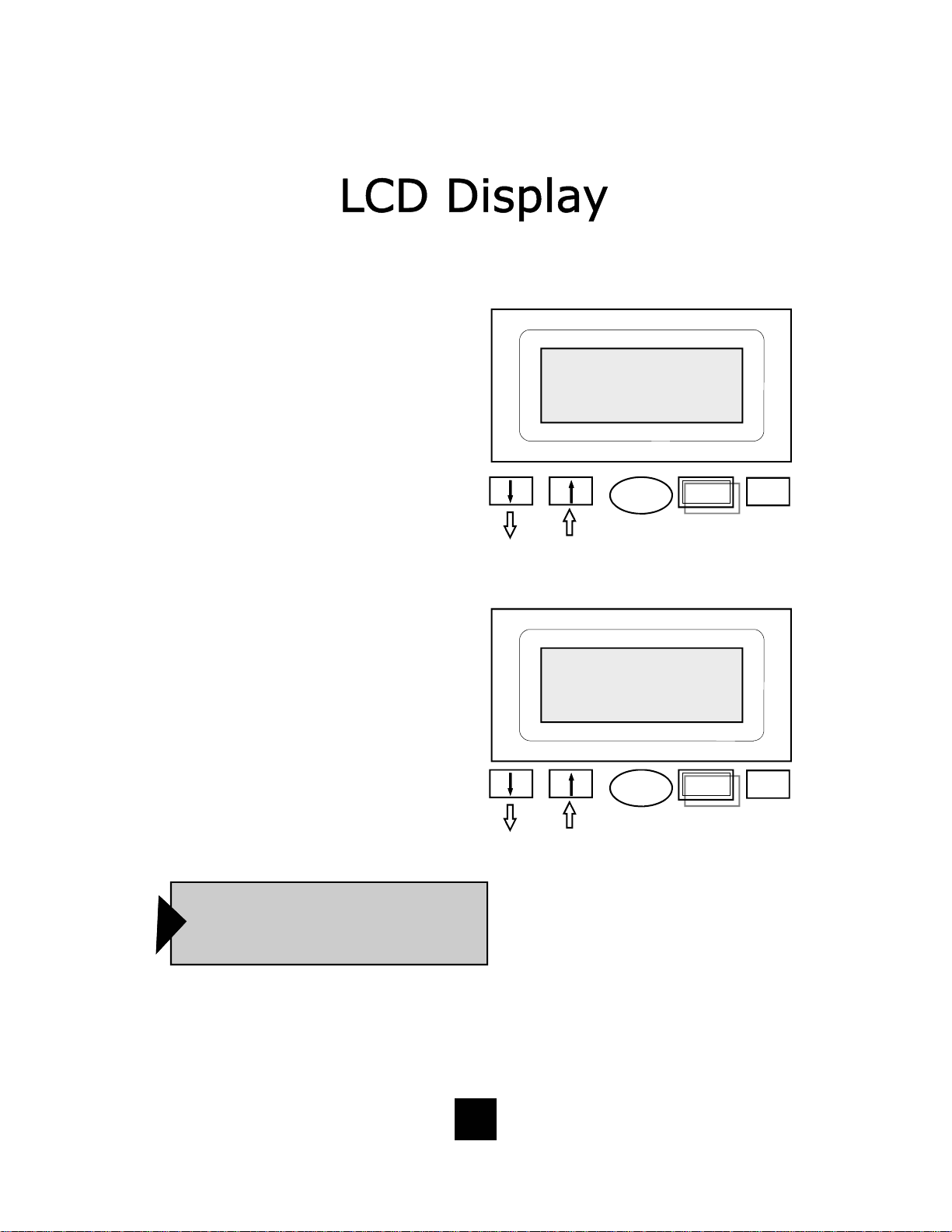
Caller Id entification (Caller I D) LCD Display Adjustments
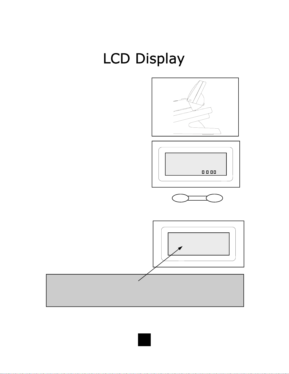
LCD Tilt Angle Feature
The LCD can b e tilted upward f or direct
viewing and easy reading. Tilt the LCD
to the desired position by lifting up the
back of LCD housing.
(60° maximum upward tilt).
LCD Contrast Feature (4-step)
The LCD cha racters can be lightened or
darkened using the volume control key.
12/01 PM12:00
While the handset is in the ON HOOK
position, simply press the volume
control key to ad just the con trast of th e
CONTRAST:
LCD screen.
To lighten characters, press
To darker characters, press
I
III
Contrast
I III
Volume
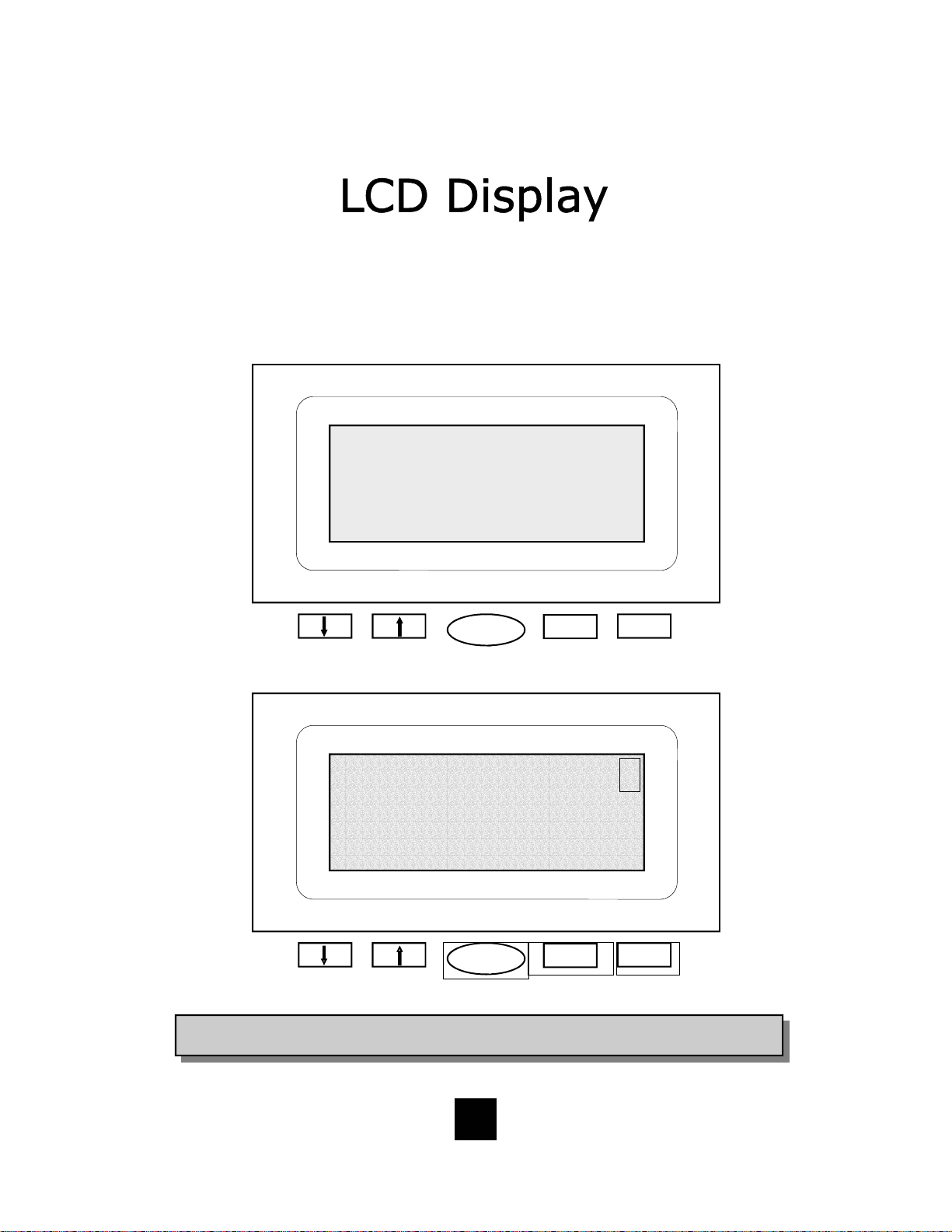
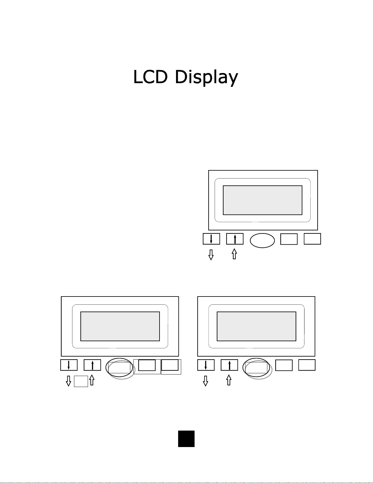
LCD Call Record Display
The LCD display will show the number
of times the same call record is received. Fo r e x am p le, when t h e identical
12/01 PM 12:00
caller calls in multiple times, the LCD
displays the number of times the caller
has called within the brackets and
7196388821
TELEMATRIX
03
[ 2 ]
shows the most recent time and date
called.
NOTE:
There are two situations: 1) No character [2] displayed if a repeat incoming call appeared after call
Caller ID Record are reviewed. 2) For the reason of limitation of memory capability, the previous call
number in the record will be dele ted automatically if a new caller ID appeared when the Caller ID
Record Log is full, in this way, it is possible for the repeat number not displayed, because the
previous record is covered by the new call.
39
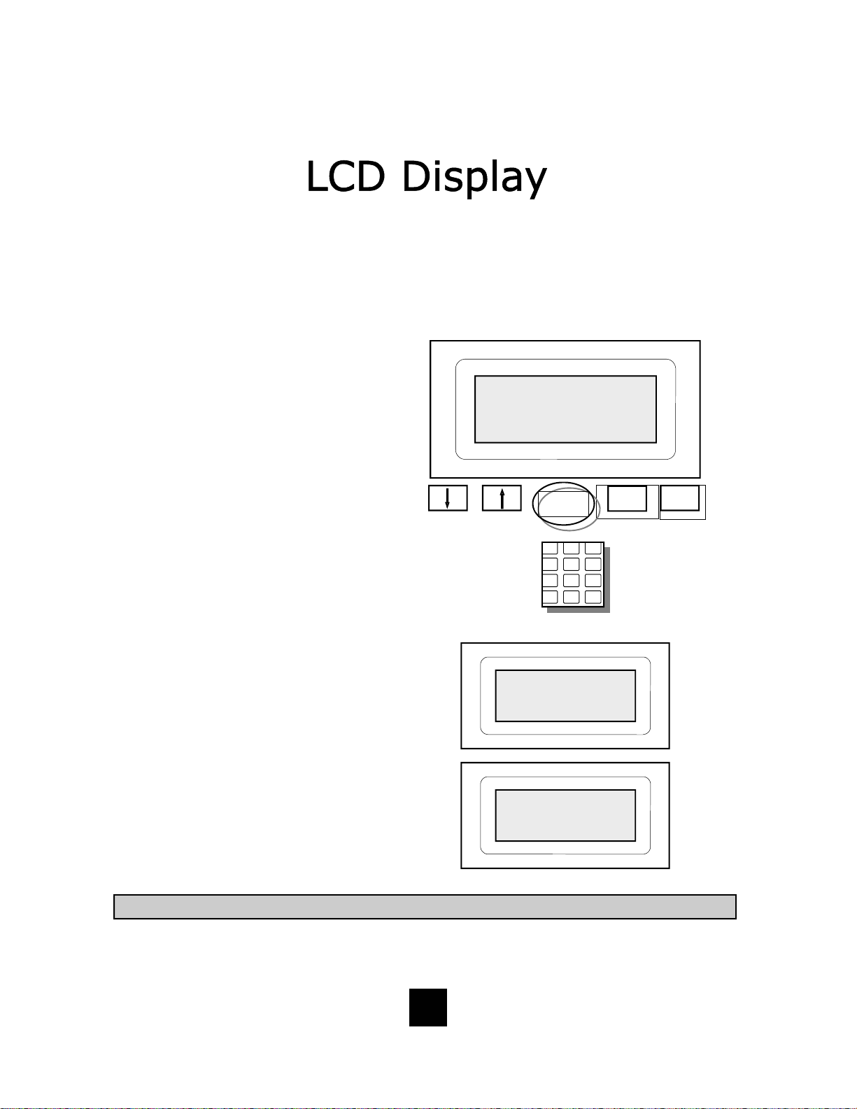
Page 40

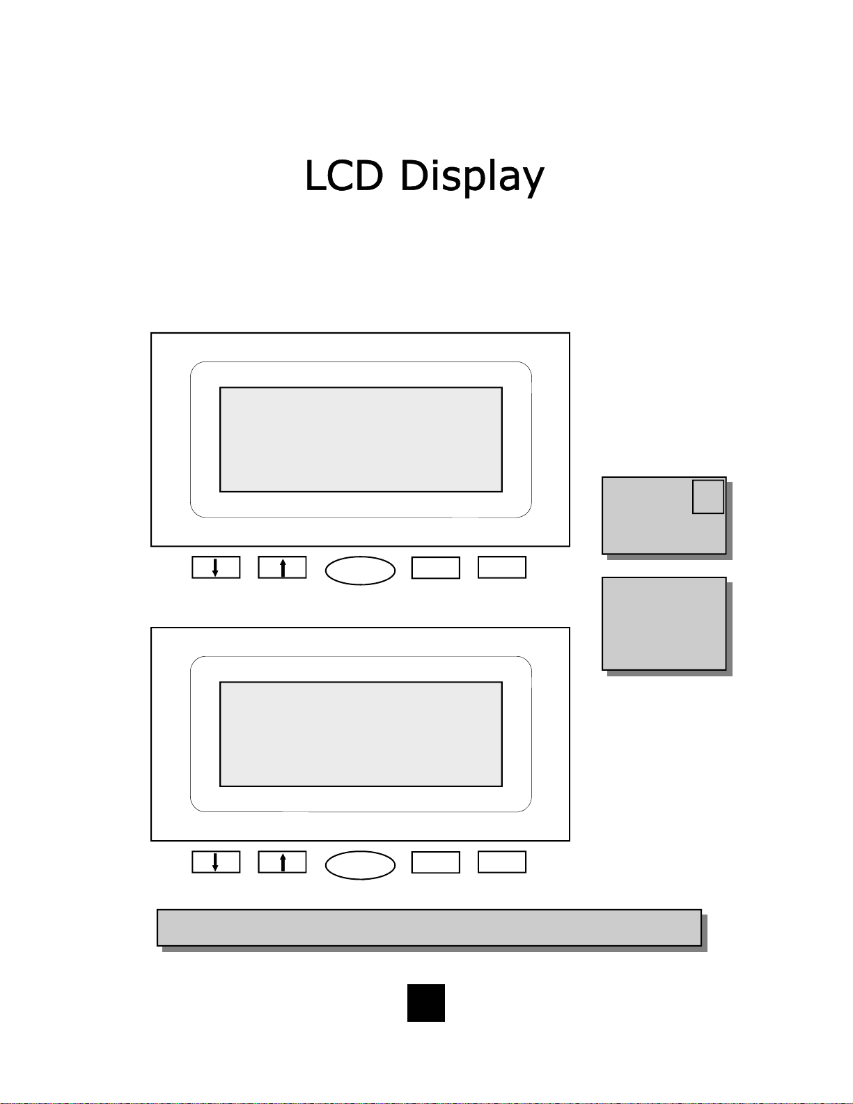
LCD (Caller ID* Display) Feat ured Icons
NEW
RPT
CALLS
12/01
PM12:00
NEW
RPT
CALLS
12/01
12:00
PM
CW
03 Caller Number
MO1 Caller Name 03:58
PhBook
Indicates New Call or Repeat Call
Indicates Speaker is ON*
Shows current date or date of call record in memory
Shows current time or time of call record in memory
Indicates Message is Waiting in Voice Mail
Indicates Handset is In-Use
Dial Delete
* Caller ID and Class Visual Message Waiting are features that require subscription to your local telephone
CW
Indicates Call Waiting Caller is On Line
03
M01
03:68
company provided services. These telephone features will not work unless you are a subscriber.
Shows Caller ID Record Location in Call Log Memory
Shows Phonebook Memory Location
Shows Elapsed Time of Current Call
40
Page 41

LCD (Caller ID* Display) Information Managem ent Keys
PhBook
Delete
Dial
1 2 3
4 5 6
7 9 8
0 #
*
NEW
RPT
CALLS
12/01
12:00
PM
CW
03 Caller Number
MO1 Caller Name
Dial Delete PhBook
DOWN Key Used to Scroll LCD Records Downward
UP Key Used to Scroll LCD Records Upward
Used to Enter Phonebook
Used to Delete Caller Log Record or Phonebook Record
Used to Dial Record Displayed Number on the LCD Screen
Used to Enter the LCD’s Edit Mode and to Edit or Enter LCD Information
Store
* Caller ID and Class Visual Message Waiting are features that require subscription to your local telephone
company provided services. These telephone features will not work unless you are a subscriber.
Used to Store Names and Numbers into Memory
41
Page 42

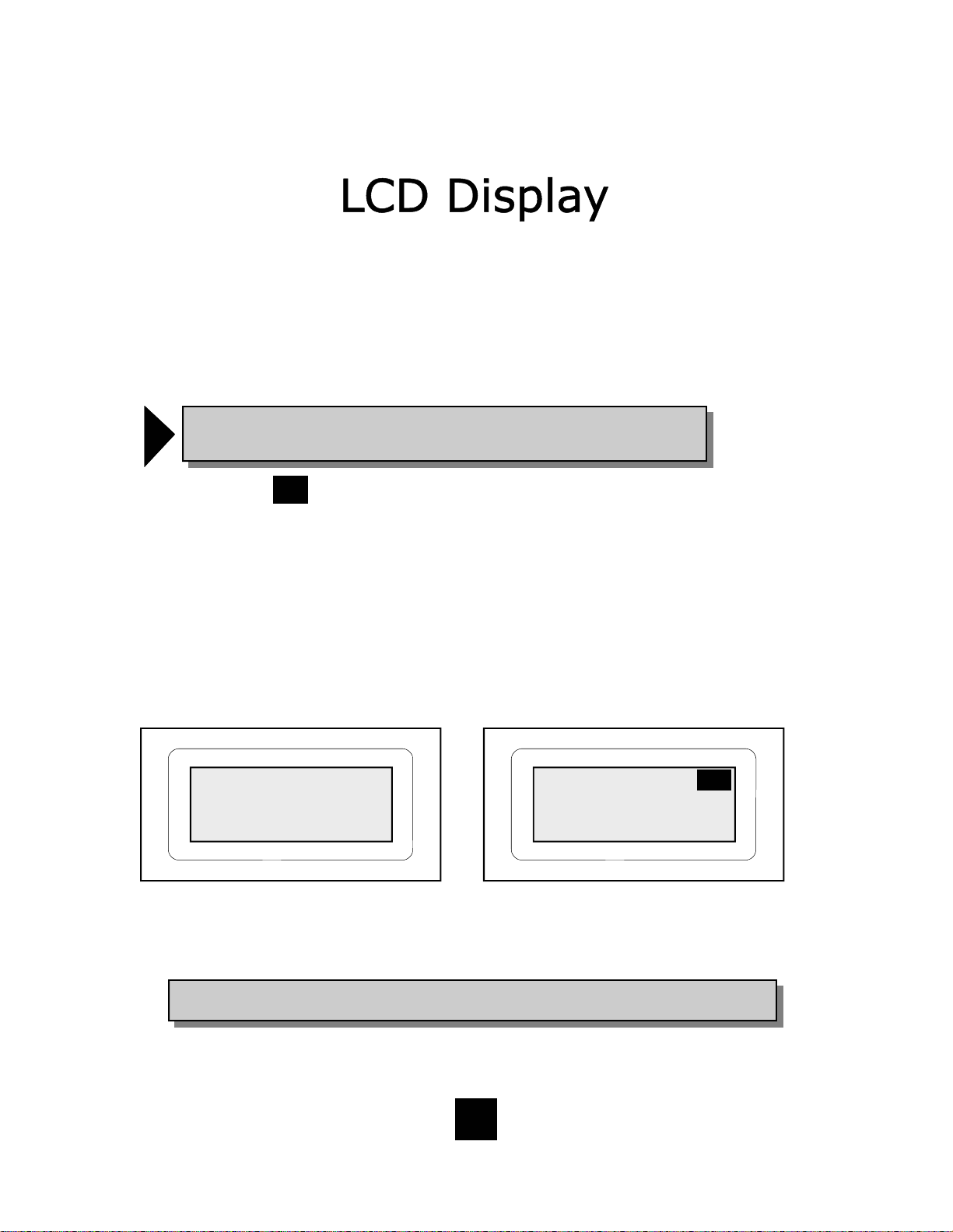
LCD (Caller ID* Display) Information when On Hook (Without Messages)
12/01
PM12:26
TOTAL
-00-
-00-
NEW
12/01
12:26
PM
-000- -000 NEW TOTAL
PhBook
Dial Delete
Shows current date
Shows current time
Indicates Zero New Messages
Indicates Zero Total Messages
Indicates Number of New Incoming Calls Since Last Retrieved Messages
Indicates Total of Messages Received and Stored into Memory (100 maximum)
* Caller ID and Class Visual Message Waiting are features that require subscription to your local telephone
company provided services. These telephone features will not work unless you are a subscriber.
42
Page 43

LCD (Caller ID Displa y) Information when O n Hook (w it h Mes sages)
PM12:26
12/01
L1
L2
-02-
-03-
12/01
12:26
PM
L1 L2 -002- -003 MSG NEW TOTAL
PhBook
Shows current date
Shows current time
Indicates Message is Waiting in Voice Mail
Indicates Line 1 has Messages Stored
Indicates Line 2 has Messages Stored
Indicates Two New Messages
Indicates Three Total Messages
Dial Delete
MSG
NEW
TOTAL
* Caller ID and Class Visual Message Waiting are features that require subscription to your local telephone
company provided services. These telephone features will not work unless you are a subscriber.
Indicates The Line that New Incoming Messages are Stored
Indicates Number of New Incoming Calls Since Last Retrieved Messages
Indicates Total of Messages Received and Stored into Memory (100 maximum)
43
Page 44
LCD (Caller ID* Display) Information when Dialing
Lift Handset
12/01
12:00
PM
Lx-IN USE
After Dialing, Elaps ed Timer Activates on Fir st Ring
12/01
12:00
PM
7196388821
IN USE 0:22
Dial Delete PhBook
Dial Delete PhBook
* Caller ID and Class Visual Message Waiting are features that require subscription to your local telephone
company provided services. These telephone features will not work unless you are a subscriber.
44
Page 45
LCD (Caller ID* Display) Information when Receiving Incoming Call
Telephone Ringing (with CID Message activated)
NEW
12/01
CALL
12:00
PM
L1 or L2 PERSONS NUMBER
PERSONS NAME
Dial Delete PhBook
After Answering Call (with CID Message activated)
12/01
12:00
PM
7196388821
Lx-IN USE 0:22
Dial Delete PhBook
If caller called
earlier and is on
the caller log
record, REPEAT CALL
will appear.
A person’s name and
number will NOT appear if you are not
subscribed to a Caller
ID and Class Visual
Message Waiting System.*
RPT
CALL
* Caller ID and Class Visual Message Waiting are features that require subscription to your local telephone
company provided services. These telephone features will not work unless you are a subscriber.
45
Page 46
Type II Caller Identification (Caller ID) Disp lay Type
The Spectrum PLUSTM LCD display supports Type II Caller ID*. This type of Call er
ID displays the identity of a second incoming call while the user is actively on a
first incoming call. The user has the option to answer the call or allow the call to
be forwarded automatically to the Users Voice Mail*.
!
NOTE: When the CW ca ll goes to voice mail, the information c a n be
retrieved at a later time using the call log.
Incoming Call Waiting
CW
When there is an active call, and another call is received, and the system is capable of Call Waiting, the Caller ID information for the incoming call will be displayed
on the screen. The display will show the following information:
1. The date and time of the incoming call, a symbol icon will appear.
2. The location number of the call in storage, and the incoming call number.
3. The incoming caller’s name.
12/01 PM12:00
6388821
IN -USE 1:24
First call is in-use
* Caller ID and Class Visual Message Waiting are features that require subscription to your local telephone
company provided services. These telephone features will not work unless you are a subscriber.
12/01 PM12:00
03 7195550000
PERSONS NAME
Second incoming call
CW
46
Page 47
Caller Identific at ion (Caller ID*) Date and T im e Information*
Setting Date & Time Manually
The Spectrum PLUS
TM
Date & Time
functions are user/installer
programmable. The Date & Time
can be set up by the user. See User
Programming for further instructions. Once the programming is
complete, the Date & Time are
maintained internally by the
Spectrum PLUS
tm
.
Setting Date & Time Automatically
The Spectrum PLUS
TM
Date & Time
functions are system programmable
when Caller ID service is activated.
The Date & Time is set initially by
the first incoming call with Caller ID
information. The Caller name and
number is displayed on the LCD between the first and second ring. Each
incoming call refreshes the Date &
Time. Between calls, the Time &
Date are maintained internally by
the Spectrum PLUS
*The Caller ID feature will operate ONLY if
you subscribe to Caller ID features with
your local telephone company and if your
PBX telephone system is equipped with the
technology required to pass Caller ID data
from the telephone line. If you are uncertain
whether your PBX telephone system can
transfer Caller ID data, contact your telephone syst em coor dinator , or yo ur PBX Ser vice Company or the PBX manufacturer.
tm
.
47
Page 48

Caller Identification (Caller ID*) Storage Capacity
Caller ID Storage Capacity
The Spectrum PLUS
TM
Caller ID
will store 100-records (numbers
and names). When memory is
full, the oldest of the 100
th
records will automatically be deleted when the newest call is accepted into memory.
NOTE:
If the same calling number con-
nects multiple times, the call log
will display the number of times
!
called and the last call time and
date only.
call
Phone Book Storage Capacity
The phonebook storage capacity
holds 100-records (numbers and
names). When memory is full, records will not delete automatically.
The user must delete the unused
records to allow new records to be
added.
NOTE:
Phonebook Records can be
placed into the phone book
manually using the keypad or
!
by saving an incoming Caller I D
record.
48
Page 49

Scrolling and Call Back Feature
The “DIAL” key allows the user to call back either stored records or the displayed number
on the LCD. A displayed number on the LCD comes from incoming calls, or from the
Phonebook memory. The Dial Back editing feature allows the user to add or delete characters to accurately pattern the number to be called. To activate the editing feature, press
any character on the keypad to activate after the record is found .
Scrolling For Stored Records
Pressing the “↑” or “↓” scrolling keys allows user to review all calls in Caller ID records.
When scrolling crosses from the most current record to first record, or from the first record to most current record stored in memory, the LCD will display “END OF LIST” indicating the rollover. Location number and time and date will also change to the date of the
call record displayed.
Instructions to find a record:
Scrolling For The Most Current Caller
ID Records
1. If the c urrent record is not displayed,
press the “↓” key to reach the most
current record.
2. Press “↓” key again to review the next
most current record.
3. Continue “↓” to continue the search.
NOTE: The DIAL key will dial any number
that is displayed on the LCD screen. If a
number is not displayed on the screen,
then there is no number in memory.
Contact your local telep hone service pro-
!
vider to see what services they offer to
recognize private party calls or anonymous calls that elect to NOT forward their
phone number.
Scrolling For The Oldest Caller ID Records
1. Press the “↓” key to reach the most
current record
2. Then press the “↑” key.
3. The LCD screen displays “END OF
LIST” indicating the CID screen is at
the beginning of stored memory.
4. Press “↑” key again to review the old-
est records in stored memory.
5. Continue next record up to continue
the search.
NOTE: Be sure to enter the area code
in AREA CODE set up. The area code
entered allows the phone to recognize
!
and eliminate your local area code
when dialing out.
49
Page 50
Deleting a Call Log Record
Delete Individual Stored
Call Record
1. Press the “↑” or “↓” key to activate
stored memory. The LCD screen
will display a record. Use the “↑” or
“↓” key to scroll to the caller record that is to be deleted.
2. Press the “DELETE” key once an d
the LCD will display the question
DELETE?.
3. Press the “DELETE” key a second
time to delete.
Delete All Stored Call R eco rds
1. Press the “↑” or “↓” key to activate
stored memory. Scroll to the first
record in memory.
2. Press and hold the “DELETE” key
for 6 seconds. The LCD will display the question “DELETE ALL?”.
12/01 PM 12:00
03 7196388821
DELETE?
or
12/01 PM 12:00
01 7196388821
DELETE ALL?
Delete
Press
quickly
Dial PhBook
3. To delete all stored calls, release
and press the “DELETE” key again
to delete all records.
NOTE: Any re cord that is delete d cannot be retrieved. To escape from deleting any record,
press the “DISC” key at any time prior to accep-
!
tance of the DELETE? question.
50
or
Delete
Press and hold
for
6 seconds
Dial PhBook
Page 51
Adding a Phonebook Record From a Caller ID Record
The Phonebook can automatically save a caller ID record into the Phonebook
memory. To add the record, simply find the record using the LCD management
keys and press the “PhBook” key.
Adding a Caller Record To The Phonebook
1. Press the “↑” or “↓” key to activate stored
memory. The LCD screen will display a record. Scroll to the caller record to be placed
in the Phonebook (f igure 1).
2. To place into phonebook memory, press the
“PhBook” key once and the LCD will display
the word “PLEASE WAIT”. The number is
now placed into memory (figure 2).
3. The LCD screen will display “REPEAT
PHBOOK” (figure 3) if the caller record has
been stored in the memory of “PhBook”.
or
12/01 PM 12:00
03 7196388821
TELEMATRIX
Figure 1
Dial Delete PhBook
12/01 PM 12:00
03 7196388821
PLEASE WAIT
PhBook
or
Dial Delete
Figure 2
51
12/01 PM 12:00
REPEAT PHBOOK
PhBook
or
Dial Delete
Figure 3
Page 52
Adding A Phonebook Record M anu a lly
Phonebook records may be added manually. To add a record, simply follow
the instructions below. All stored records in the Phonebook will be displayed
in alphabetic order.
Manually Adding A Phonebook
Record Into Memory
1. The phone must be ON-HOOK (in the
cradle).
2. Press the “STORE” key.
3. Press the “PhBook” key. The display
will show “ENTER NUMBER” (figure
1).
4. Input the number using the keypad
(figure 2).
5. Press the “STORE” key again. The
display will show “ENTER
NAME” (figure 3).
6. Input the name using the keypad
(figure 2).
7. Press the “STORE” key again. The
display will show “PLEASE
WAIT” (figure 4).
8. The display will default to the original
screen.
9. To add additional records, repeat line
items 2 through 7 above.
12/01 PM12:00
ENTER NUMBER
PhBook
1 2 3
4 5 6
7 9 8
0 #
*
KEYPAD
12/01 PM12:00
ENTER NAME
12/01 PM 12:00
PLEASE WAIT
Dial Delete
Figure 1
Figure 2
Figure 3
Figure 4
NOTE: A maximum of 32-digits can be entered into ENTER NUMBER and 12-characters into ENTER NAME.
52
Page 53

Dialing From the Phonebook Directory
To Dial From the Phonebook Directory
1. Press the “PhBook” key to enter into the
Phonebook mode.
2. To locate the desired record, Scroll the “↑”
or “↓” key or use the Hyperlink Feature below along with the “↑” or “↓” key to fi nd a
record. (See th e Hyperlin k Feature note below).
3. Once the record is found, press the “DIAL”
key.
Hyperlink to a Stored Record
1 2 3
4 5 6
7 9 8
0 #
*
Note: The keypad only recognizes the first keypad character of each key.
For example;
“2” = records beginning with A, then scroll for B and C records.
“3” = records beginning with D, then scroll for E and F records.
“4” = records beginning with G, then scroll for H and I records.
“5” = records beginning with J, then scroll for K and L records.
“6” = records beginning with M, then scroll for N and O records.
“7” = records beginning with P, then scroll for Q, R and S records.
“8” = records beginning with T, then scroll for U and V records.
“9” = records beginning with W, then scroll for X, Y and Z records.
For scrolling, use the UP or Down key to scroll to the name being searched.
PhBook
Dial
or
1 2 3
4 5 6
7 9 8
0 #
*
OR USE
HYPERLINK
BELOW
53
Page 54

Call Record Editing Prior to Dialing
To Add Characters to the
Displayed Number
1. Press the “↑” or “↓” key to activate the
display for scrolling.
2. Scroll the “↑” or “↓” key to find the
number to be dialed.
3. Activate the editing feature by pressing
any number on the keypad. (Note that
the key pressed will be displayed on the
LCD).
4. Press the keypad number you require
and it will appear on the LCD prior to the
number on the display.
5. Lift handset or activate the “SPEAKER”
key.
6. Press the “DIAL” key to dial the num-
ber automatically. When pressing the
“DIAL” key, the “SPEAKER” will activate.
Note: The number can only be inserted prior to the
displayed digits. See Delete Characters for
improper inserted characters .
To Delete Characters from the
Displayed Number
1. Press the “↑” or “↓” key to activate
the display for scrolling.
2. Scroll the “↑” or “↓” key to find the
number to be dialed.
3. Activate the editing feature by
pressing any number on the keypad.
4. Press the “DELETE” key to delete
individual characters.
5. Lift handset or activate the
“SPEAKER” key.
6. Press the “DIAL” key to dial the
number automatically. When pressing the “DIAL” key, the
“SPEAKER” will activate.
Note: When deleting char acters from a
caller’s identity, the Call Log will not b e
changed.
!
1 2 3
12/01
03 719638
TELEMATRIX
PhBook
12:00
PM
8821
Delete
Dial
PLUS
4 5 6
7 9 8
0 #
*
EDIT NUMBER
THEN PRESS DIAL
WITH KEYPAD
or
NOTE: The area code initially programmed into the AREA CODE menu then recognizes
your local area code and eliminates these numbers when dialing out.
54
Delete PhBook
Dial
Page 55

Other LCD Display Messages
“No Calls” Display
This message will display when
there are no call records received
since last using the Caller ID features menu when the “↑” or “↓” key
is pressed.
“Line Error” Display
Indicates that there was a line error when attempting to connect to
the dialed party. Retry the phone
call. If “lin e er ro r” continues, ch e ck
for dial tone. If no dial tone, call
your local service pr ovider.
“Invalid Entry” Display
Indicates that the entry is not recognized or is outside the parameter of the range for that specific
function. LCD display the “INVALID
ENTRY”.
12/01
NO CALLS
12/01
LINE ERROR
12/01 PM 12:00
INVALID ENTRY
12:00
PM
12:00
PM
“PhoneBook Full” Display
Indicates that the phonebooks
memory has the maximum of 100
records. To add more phone records, delete records that are not
used to free up memory.
55
12/01 PM12:00
PHONEBOOK FULL
Page 56

In-Us e I ndicat ors
In-use indicator lights located above each key indicate in-use operations.
Line 1 / Line 2 Indicators
Line Key selector keys are provided
for ease of line selection. When the
Line is in-use, the in-use light above
the Line key will illuminate steadily
GREEN. “Lx-IN-USE” will be displayed
on the LCD screen when in use.
Speaker Line Indicators
When the “SPEAKER” key is activated, the in-use light illuminates
steadily RED above the “SPEAKER”
key. The word “SPEAKER ” will be displayed on the LCD screen when active. The in-use line will be steadily
GREEN.
Conference Indicators
When the “CONFERENCE” key is
activated, The word “CONFERENCE”
will be displayed on the LCD screen
when active. Line 1 and Lin e 2 LE D
Indicators will change from RED to
GREEN.
Hold Key Indicators
When the “HOLD” key is activated,
the in-u se li ght above t h e Li ne- In-U se
will change from steadily GREEN to
steadily RED.
Headset Key Indicators
When the “HEADSET ON/OFF” key
is activated, the in-use light above
the Line-In-Use will be steadily
GREEN and the Headset indicator will
be steadily RED. The LCD will display
“HEADSET” when active.
56
Page 57

Placing a Call Using the
Speakerphone
The Spectrum PLUS
TM
is equipped with a
high quality speakerphone feature to
allow for hands-free operation. To use,
simply press th e “SPEAKER” key when
placing or answering a call. The telephone line will activate automatically.
When the “DIALPAD” Feature is programmed to be ON, the speakerphone
will become active when pressing any
number on the dial pad keys.
The LED abov e t h e “SPEAKER” key will
illuminate to indicate that the speakerphone is in-use.
To hang-up, press the “SPEAKER” key
again.
To use the handset, pick up the handset
from the cradle and the handset will be
active. The speakerphone will disconnect. To re-activate the “SPEAKER”
key, press the “SPEAKER” key and
place the handset back into the cradle.
Autoline Select Feature —
For 2 line phones, when activating the ha nd s e t , s p e a k e r, o r
headset for dialing, the phone
!
will automatically select the
open line. The first line f or auto
selection is Line 1, then Line 2.
57
Page 58

Using The Conference Feature
The “CONFERENCE” key is used to
establish a 3-way conversation. The
conference feature is activated by a
“soft” key and will automatically reset
when hanging up.
A 3-way conference call can be established while using either the handset,
speakerphone or headset.
To use the “CONFERENCE” feature:
1. Pla ce the line that is curren tly in-use
on hold by pressing the “HOLD” key.
The line status indicator will turn from
GREEN to RED.
2. The second call can be established by
selecting the idle line key and dialing
the call using the keypad, Caller ID
record, or Phonebo ok r e co rd .
3. When the second call is established, activate the 3-way conference call by
pressing the “CONFERENCE” key. Line 1 and Line 2 will automatically
bridge together and all three parties can now converse.
4. To end the call, simply hang-up by placing the handset back in its cradle
(on-hook) or by pressing the “SPEAKER” key. Both callers will drop-off and
both lines will hang up. The telephone is now back to its on-hook, idle state .
5. To continue speaking with one of the callers and want to “drop” the second
caller, simply press the line key of the caller to continue speaking. The
other line will automatically hang up.
58
Page 59

Using the Data Port
The Spectrum PLUS
TM
is equipped with a
convenient data port on the bottom of
the base unit. This modular receptacle
is used to plug in any standard
telephone device such as a computer
modem, answering machine, or fax
machine.
Note: The data port use s line 2.
59
Page 60

Using the Hold Feature
The “HOLD” key is used to place a
caller on hold. To use, simply press
the “HOLD” key. The LED above the
“HOLD” will illuminate to indicate that
this line is on hold. The LCD will display the word “HOLD” when active.
When the “HOLD” key is active, the
handset can be lifted off-hook or
returned to its on-hook position and
the line will not be disconnected. To
return to the caller, simply lift the
handset and press the “SPEAKER”
key or and press the line-in-use key
and the “SPEAKER” key will automatically activate for hands-free operation.
Hold will also release when the call is
picked up from an additional extension
phone.
60
Page 61
Using The Mute Feature
A “MUTE” key is provided to allow
privacy during a background conversation. When the “MUTE” key is activated, the microphones in the handset, speakerphone and/or headset are
disabled. When the “MUTE” key is
activated, the caller will not hear
voice. “Mute” will be displayed on the
LCD to show that the feature is activate. To de-activate, press the
“MUTE” key again.
61
Page 62

Using the Redial Feature
The “REDIAL” key is used to
automatically redial the last number
that was dialed from the keypad.
To use:
• Lift the handset (or activate the
speaker).
• Press the “REDIAL” key.
• The last number dialed will be
redialed.
Or
• Simply Press the “REDIAL” key and
the last number dialed will be
redialed.
Autoline Select Feature — For 2 line phones, when activating the
handset, speaker, or headset for dialing, the phone will automatically
f
select the open line. The first line for auto selection is Line 1, then
Line 2.
62
Page 63
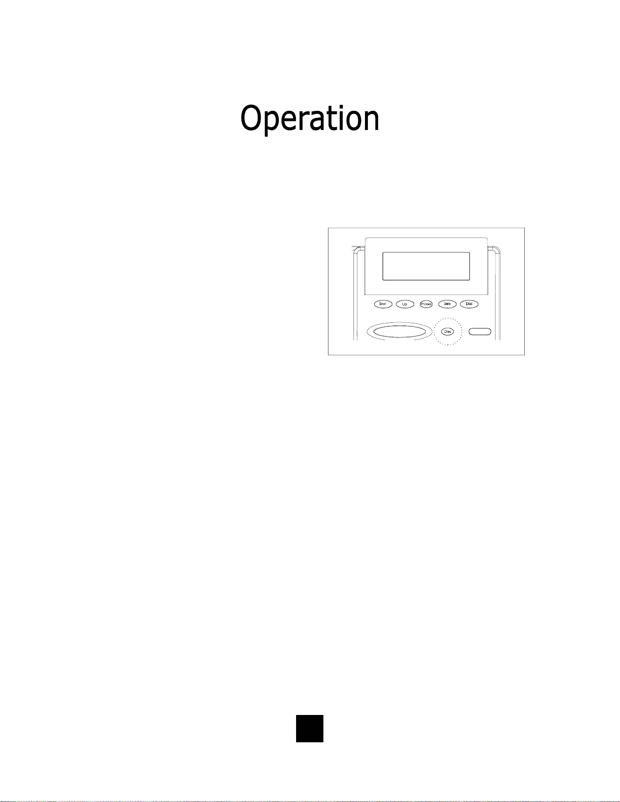
Using The Disconnect Feature Key
The “DISC” (DISCONNECT) key is a
2-second electronic timed line break.
The key can be used to automatically
hang-up the call that you are currently
on and regain a new dial tone to
establish a new call.
To use:
• Simply press the “DISC” key
when the conversation is complete.
• The “DISC” key can be used in
Speaker mode, on-hook, off-hook
or conference.
• The “DISC” key can be u sed with
headset or handset activation.
• The “DISC” key provides a con-
venient way to disconnect the line
when not using the handset.
63
Page 64

Handset Volume Control
The Spectrum PLUS
with an ADA/FCC compliant handset
volume control located on the front of
the phone.
When the right end of the “VOLUME”
key is pressed, the volume of the
handset rece iver is increased.
When the l eft end of the “VOLUME”
key is pressed, the volume of the
handset receiver is decreased.
The “VOLUME” key is an eight-step
volume control key.
TM
is equipped
Volume Lock Feature — When the handset, sp eaker, or
headset volume feature is selected, the volume will
f
automatically stay at that setting in the next use.
64
Page 65

Keep the telephone dry. If it gets wet on the outside,
wipe it d ry imme diately. Liquids might contain minerals
that can corrode the electronic circuits. Do not touch the
unit if submerged in water. Call for assistance.
Use and store the telephone only in normal temperature
environments. Temperature extremes can shorten the
life of electronic devices, damage batteries, and distort
or melt plastic parts. Avoid direct sunlight.
Keep the telephone away from excessive dust and dirt
that can cause premature wear of parts.
Wipe the telephone with a damp cloth occasionally to
keep it looking new. Do not use harsh chemicals, cleaning solvents, or strong detergents to clean the unit.
65
Page 66

When problems arise during installation or service that cannot be
resolved using this or related documents, contact the TeleMatrix Priority Care Department, Monday through Friday, 8:30a.m. - 4:30p.m.
MST:
Toll Free: 1-800-462-9446
Direct: 719-638-8821
Fax: 719-638-8815
www.telematrixusa.com
Many times a problem is either installation or user related. Please
contact TeleMatrix PRIOR to sending a telephone to our service center
for repair. In the unlikely event that a factory repair is necessary:
1. Include a brief description of the problem that you are
experiencing.
2. Include a proof of purchase for a repair under warranty.
3. Send the telephone prepaid by UPS or Parcel Post, insured to:
TeleMatrix, Inc.
Priority Care Center
5025 Galley Road
Colorado Springs, Colorado 80915
TeleMatrix will pay return postage on the repaired telephone. Allow
2-3 weeks fo r delivery. When im mediate repl acement i s required, see
our FastLane
SM
replacement policy on our internet site.
66
Page 67

STATEMENT OF LIMITED WARRANTY
TeleMatrix, Inc . ( TMX) warrants to its [original end c ustomer] [purchaser ] that Spectrum and
Marquis branded products manufactured by TMX are free from defects in mate rials and workmanship
for five (5) years, SpectrumPLUS two (2) years after the date of purchase, and Regency branded products
manufactured by TMX are free from defects in materials and workmanship for three (3) years, other than
the following products for which the warranty per iod s hall be one (1) year: handset batter ies , either
NiCd or NiMH, used in TMX cordl ess product s. If a pro duct fails t his warranty d uring the warra nty
period, TMX will, at its option, either repair or replace the defective product or parts, or deliver
replacements for defective products or parts on an exchange basis at no additional charge to the
customer except as set forth below. Repair parts or replacement products may be either new or
reconditioned. Products or parts returned to TMX under this warranty will become the property of
TMX. Warranties on products repaired by TMX expi re at the termination of the original warranty
period.
This limited warranty does not cover:
1. Products or parts wh ich are damaged, abused or misused;
2. Any damage resulting from improper installation , maintenance or operation of the product;
3. Damage resulting from unauthorized modification or repair of the product, or from improper
connection of the product to other equipment;
4. Cords, connectors and replaceable batteries;
5. Damage in transit to the TMX repair facility;
6. Any product or part unless proof of date of purchase is submitted with the product when
returned for warranty repair; or
7. Costs incurred by the customer in remo ving and shipp ing the product t o TMX for repair o r
replacement, and costs of reinstallation of the product.
8. Products or parts which are not owned and used by the original end user customer.
The cost and risk of loss or da ma ge for sending the product to TM X will be borne by the cu s tomer .
TMX EXPRESSLY DISCLAIMS ALL WARRANTIES EXCEPT THE LIMITED WARRANTY SET FORTH
HEREIN, WHICH IS THE SOLE AND EXCLUSIVE WAR RANTY OF THE PRO DUCT, AND IS IN L IEU OF
ALL OTHER WARRANTIES, WHETHER ORAL OR WRITTEN, EXPRESS OR IMPLIED, OR STATUTORY.
THERE ARE NO IMPLIED WARRANTIES OF MERCHANTABILITY OR FITNESS FOR A PARTICULAR
PURPOSE. THE CUSTOMER’S SOLE REMEDY UNDER THE TMX WARRANTY SHALL BE REPAIR OR
REPLACEMENT AS PROVID ED ABOVE. IN NO EVENT WILL TMX BE LIABLE TO CUSTOMER OR ANY
OTHER PARTY FOR ANY INDIRECT, INCIDENTAL OR CONSEQUENTIAL DAMAGES, INCLUDING,
WITHOUT LIMITATION, DAMAGES OF LOST PROFITS, LOST REVENUES, LOSS OF USE OF FAC ILITIES OR EQUIPMENT, OR COST OF SUBSTITUTE EQUIPMENT ARISING OUT OF THE USE OR INABILITY TO USE THIS PRO D UCT, EVEN I F TH E CUSTOMER H AS ADV ISED TMX OF THE P OSS IBILITY
OF SUCH DAMAGES. TMX LIABILI TY FO R DAMAGE S SHALL NOT EXCE ED T HE P URCHASE PRICE OF
THE DEFECTIVE PRODUCT.
This limited warranty is non-transferable without the prior written approval of TMX. It gives the
customer specific legal rights. The customer may have other rights which vary under local law.
Some jurisdictions may not allow limitations on the term of an implied warranty or exclusions or
limitations of incidental or consequential dama ges .
67
Page 68

68
 Loading...