

Page 1

Page 2

This page is intentionally left blank
Page 3

Congratulations on your purchase of the TeleMatrix Spectrum PLUSTM Series
DC640 Di gital Ce ntrex Te lephone.The DC640 i ncludes advanc ed f eatures
that ar e suitable i n to day’s bus iness e nvironment.The DC640 i s equipped
with preprinted feature/line keys which can be used to customize your telephone features and line appearance.
TeleMatrix designed the DC640 to be simple to install and easy to use. The
DC640 is for use behind a Nortel Meridian Digital Centrex environment provided by your local telephone company. It has a two line LCD display which
displays local business telephone features and switch features that are provided by your telephone service provider. Switch features must be ordered
from your local telephone provider. Local features provide you the convenience of customizing your DC640 telephone for your personal use.
The DC640 D igital C entrex Te lephone is a precision electronic d evice t hat
requires m inimum maintenance. Pl ease b e su re t o read t he c ontents set
forth i n the us er’s gui de to be come f amiliar wi th c onnecting and the
functionality of this product.
Contact yo ur T elephone Admi nistrator or yo ur l ocal te lephone Cus tomer
Service Representative for proper set up of your telephone network.
As specified by FCC regulation, we are required to inform you of specific governmental
and compliance regulatory requirements, safety notices, safety i nstructions and other
informative information. TeleMatrix, Inc. provides this information in a separate manual. We pack the separate Compliance and Safety Manual within each outer box or
product box when shipped.
Prior to reading this operation manual and prior to setting up your tele phone, please
refer to the Compliance and Safety Manual.
3
Page 4

Features .........................................………...................................... 5
Controls …….................................................................................. 6
Part List ……………………………………………………………………………………………...….. 10
Installation ....……......................................................................... 11
Programming ..……..............................…....................................... 15
LCD Display/Caller Identification …………..…..………………………………..……... 28
Headset Installation and Operation……........…................................... 31
Operation ………………………………………………………………………...……………………. 33
Care and Maintenance ……………………………………………………………………….…. 39
Service ………………………………………………………………………………………………….. 40
Warranty ………………………………………………………………………………………………. 41
FCC Compliance and Safety Instructions, Warra nty and Service Information may
be f ound in a s eparate m anual w ithin th is pa ckage. I f th ese/this ma nual is n ot
found in this products packaging, then immediately contact your local supplier
4
Page 5

• Digital Centrex Operation with multi-line functionality
• SteelTrap
• FreeSpeech
Speakerphone
TM
Memory Technology (No Batteries Required)
TM
T alk F eature: A llows F ree T oggle be tween H andset, Headset an d
• Forty (40) Access Feature Keys with LED Indicators (Key #M01-M40)
• TouchLite
TM
One Touch Message Retrieval Key (Key #M12)
• Visual Message Waiting Indication and Visual Ringing Indicator
• Large, 2-line x 24-Character LCD Display
- Contrast Adjustable, 16-step
- Backlit LCD Display
- Display for Additional Call Information
- Programmable Date & Time
- Programmable Date and Time Format; 12 or 24 Hour Clock
- Ten (10) Programmable Dialing Memory Locations; 20 digit capacity
- Elapsed Call Timer
- Multiple Language Support; English, Spanish, and French
• LCD Display Management Keys; Up and Down Scrolling
• LCD Display Programming Keys; Exit, Select, Save
• Hands Free 2-Way Speakerphone (Half Duplex) with LED Indication
• Headset Port with ON/OFF Key (built-in Amplifier) with LED Indicator
• Speaker, Handset, Headset, and Ringer Volume Control (Soft Key Toggle Switch)
• ADA Compliant Handset with 16-step Volume Control
• Microphone Mute Key with LED Indication
• Electronic Hold Key (must be provisioned for hold)
• Programming Keys; Program, Memory, Pause, Store, Up, and Down
• Memory Review Key
• Pause Key for Programming a 1.0 Second Timing Delay
• Release Key to Disconnect Call
• On Hook Pre-dialing Feature; On Hook Dialing (User Set Up)
• User Programmable Answering Default Location; Headset or Speaker
• Programmable Primary Directory Number (PDN)
• LED Indicators show ON/OFF, Flash and Wink Key Status
• Telephone Reset Feature (removes all data)
•
Wall Mount or Desktop Placement
5
Page 6

6
Page 7

1. Access Feature Keys ….…………..…………... Forty (40) illuminated pr ogrammable on e touch ke ys used fo r l ine or Ce ntrex fe ature
acce ss.
TM
2. To uchlite
Key...…………………………………... Message Wai ting L amp (L ED i ndicator) t hat
blinks to in dicate a n ew mes sage in th e
user’s vo ice m ail b ox (use r m ust b e
subscribed to a messaging system).
3. Release Key …………...…………………...……… Used to disconnect the line, or exit the
pro gramming mode.
4. Store Key ………...…………………………….….… Used t o p rogram a si ngle, re adily avai lable
number for later retrieval.
5. Pause Key ...............................………… Used to program a 1.0 second timing delay
in speed dial memory or on hook dialing.
6. Memory Key ................………………………. Used to initiate ten (10) programmed
memo ry locations.
7. Programming Key .............................… Used to initiate programming mode.
8. Hold Key ……………………………………………..… Key used for placing callers on hold.
9. Mute Key …………………………….………………... Lighted key used for disabling the handset,
headset and speakerphone microphone.
10. Headset ON/OFF Key ……………………………. Used to turn the headset ON or OFF. LED
Ind ication.
11. Numeric Dial Pad ………………...………………. Used for outbound dialing.
12. Speaker Key .………………...................…… Used to turn the speakerphone ON or OFF.
LED Indication.
13. Volume Bar …………………..……………………….. Adjusts t he l oudness i ndependently fo r t he
handset receiver, the headset, speaker and/
or ringer.
14. Up and Down Scroll Key ..….........……..… Used to scroll the LCD through the program
menu and Memory Dial records. Also used to
adjust LCD contrast.
15. Exit Key ..………................…….....….…..… Used to exit programming mode or memory
dialin g mode.
16. Select Key ……………………………..…………..... Used for programming settings.
17. Save Key ……………………………………………... Used to save programmed settings.
18. Handset ……………………………….…………...... Hearing-aid compatible handset.
19. LCD Display ...............…….............……… Large adjustable backlit LCD display.
7
Page 8
8
Page 9

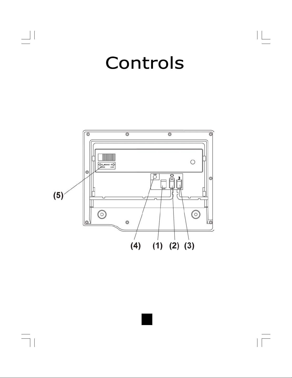
1. Line Jack …...…………………………………… Modular receptacle for connecting
the line cord.
2. Headset Jacks ............................. Convenient RJ port or 2.5mm
coaxial port used to connect an
optional headset.
3. Handset Jack .............................. Connection for handset coil cord.
4. Power Adapter Receptacle ……..……. For optional coaxial power
adapter.
5. Elevation Stand Lock ……………………… Used to “lock” the elevation
stand.
9
Page 10
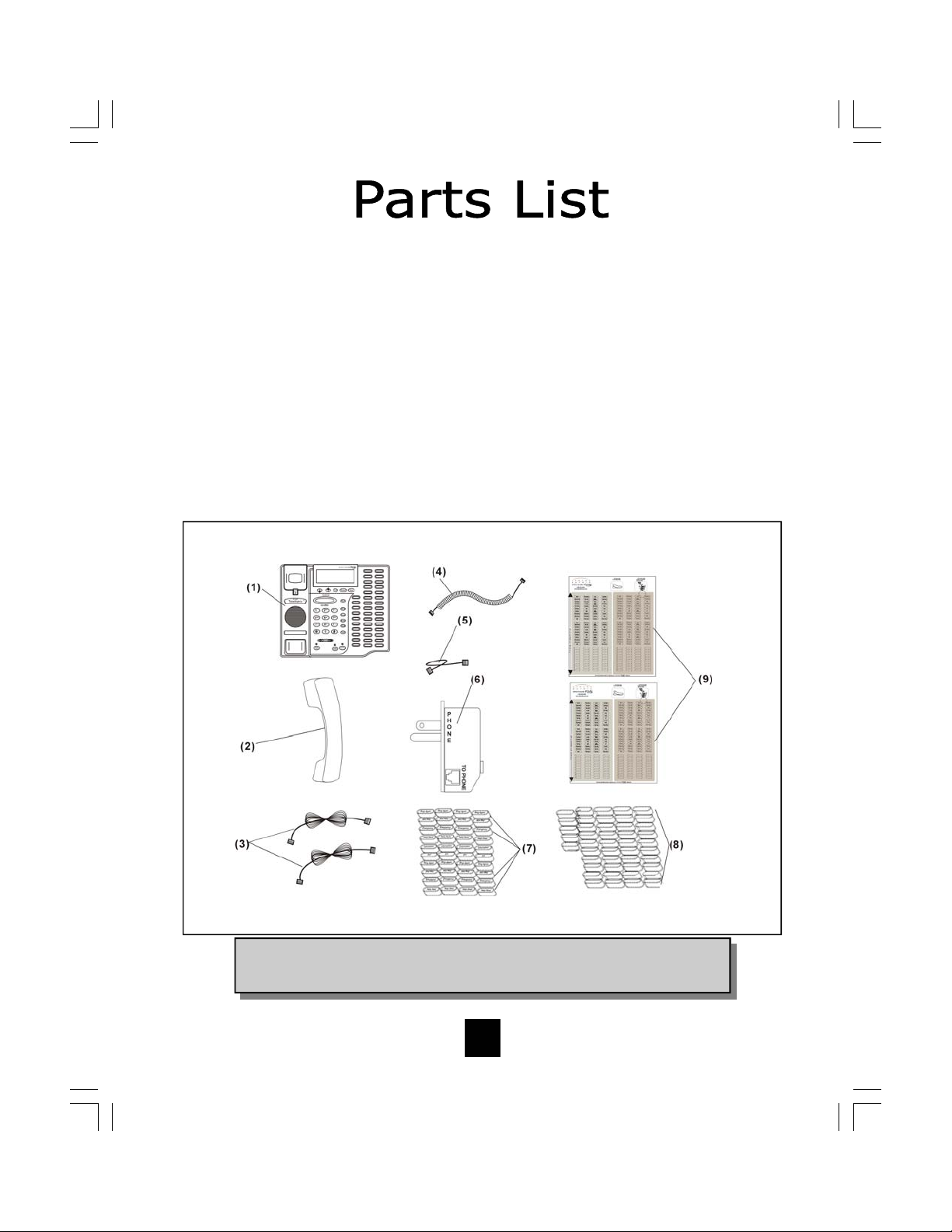
Parts Check List
The following parts are included with the Spectrum PLUS
1. Bas e Unit
2. H andset
3. 15 foot Modular telephone line cords (2).
4. 10 foot Modular coiled handset cord.
5. 6 inch Modular wall mount line cord.
6. Power Adapter with Pass-Through AC Outlet.
7. Forty (40) Preprinted Feature Keycaps
8. Forty-five (45) Clear Keycaps
9. Preprinted Feature Key Index Sheet and Blank Labels
TM
DC640:
NOTE: Spectrum PLUS
cords (6P6C line cord). Replacement Line Cords must be same.
TM
Line Cords are 6-Pin 6-Conductor Line
10
Page 11

Caution
• Never install telephone wiring during a lightning storm.
• Never i nstall t elephone j acks i n wet l ocations u nless t he j ack i s
specifically designed for wet locations.
• Never t ouch uni nstalled te lephone wi res or ter minals unl ess the
telephone line has been disconnected at the network interface.
• Use caution when installing or modifying telephone lines.
Power Outlet Required
The Sp ectrum PLUSTM Series te lephone requires exter nal po wer f rom a
standard 120V outlet (60Hz). Upon loss of electrical power, the telephone
will operate. All the features will work however, only the 2 bottom right
keys will have LED illumination . Dial Tone will be available as long as the
dial tone is available from the telephone company.
IMPORTANT!
The telephone will not function if the line cord connections are not correct. Be
sure th at th e te lephone lin e c ord c onnections are n ot rev ersed
(“LINE”/”PHONE”). Attach the line cords to the power adapter and the wall be-
!
fore c onnecting to the t elephone. S pectrumPLUS
Conductor Li ne co rds (6 P6C l ine co rd) . Re placement Li ne Co rds m ust be t he
same. The DC640 is polarity sensitive. Tip and ring cannot be reversed.
TM
Lin e C ords are 6- Pin 6-
11
Page 12

120V AC Outlet Recovery Power Adapter (provided)
The 120 VOL T A C OUTLET ADAP TER i s a p roprietary TeleMatrix pr oduct. It p rovides both the telephone lines and the power source in one cable (6P6C line cord)
and is designed to recover the use of the AC power outlet.
Connector Configuratio n
The 120V O utlet Re covery Power Adapter has two (2) mo dular jacks. One jac k i s
labeled “LINE INPUT” and the other jack is labeled “TO PHONE”. These jacks allow
for a fully modular installation.
Power Adapter “LINE” Connection
The power adapter s “L INE INPUT” c onnection is us ed to c onnect the te lephone l ine
from the wal l jac k to the po wer adapter .
Using o ne o f the 15-f oot modular te lephone
line co rds, connect on e en d o f t he c ord t o
the RJ14 te lephone jack on the wall or base
board. The remaining end o f the l ine c ord
plugs i nto the “L INE ” s ide of the p ower
adapter.
Power Adapter “PHONE” Connection
The power adapter “TO PHONE” connector is
used to p rovide both the telephone line and
the po wer source to operate the t elephone.
Using o ne of the 15-f oot modular t elephone
line cords, plug one end of t he line cord into
the bac k of the t elephone. Plug the remaining e nd to the po wer adapter jac k l abeled
“TO PHONE”.
Troubleshooting Note: If there is no power to the telephone
after c onnecting the line c ords, c heck to s ee if the line cords
were inserted in the opposite sides of the adapter.
12
Page 13

Connecting the Handset Cord
A 10-foot modular coil handset cord is
provided. ( Be sure that the wall/desk
elevation stand has not been
attached). To i nstall t he c ord, si mply
plug the short straight end o f the
handset cord into the modular jack on
the handset. The long straight end of
the hands et c ord pl ugs i nto the jac k
labeled “ Handset” located o n the
bottom of the Sp ectrum PLUS
TM
base
unit. Place the line cord into the handset c oil co rd channel l ocated directly
below the jack.
NOTE: Be sure that all line cord connections are made prior to installing the Wall Mount Wedge. An
optional direct connect coaxial power supply can be used or the provided power supply can be used.
Desk Mounting
To in stall th e wedge for desk mou nting, be s ure the loc k mechanism is pos itioned to th e
left, clear of the locking arm. Place the wedge in the slots, wide end toward top of phone
base unit, and slide the wedge upward into position. Lock the wedge into place.
13
Page 14
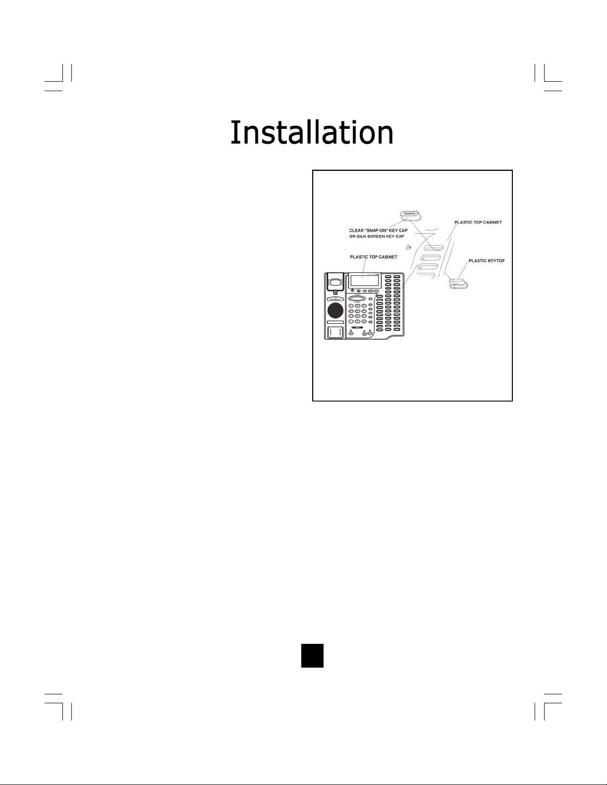
Installing Access Feature Keycaps
Forty ( 40) p reprinted a ccess f eature
keycaps are provided for placement on
the access fea ture ke ys. These ke ycaps i dentify t he k eys use. Th ere a re
45 c lear k eycaps pro vided for p rinted
labels to be inserted.
To i nstall the pre-printed keys, simply
remove t he clear ke ycap b y p ulling i t
up with a f ingernail o r s harp o bject.
Replace wi th the pre printed keyc aps
or pl ace hand written paper i ndex
sheets u nder a cl ear k eycap. Po sition
the k eycap o nto the key and pre ss
downward to snap the k eycap on.
(figure 1)
Contact yo ur local t elephone a dministrator fo r s pecific in struction o f t he
keys to use and their location.
Key Selections
Figure 1
Agent
Agent Avail
Agt Status
Ans Agent
Ans Emergency
Auto Callback
Auto Dial
Auto Line
Call Agent
Call Fwd
Call Park
Call Supv
Call Wait
Conf
Conf 3
Conf 6
Conf/Transfer
Cwt Cancel
DND
Dir Pickup
Dis Agt Sum
Disp Queue
Drop
EMK
Emergency
End To End
Exec Msg Wtg
Flex Call
Force Call
I/C
I/C Group
In Calls
Inspect
Interflow
Leave Msg
LOB
14
Make Busy
MCH
Night Serv
Not Ready
Obs Agent
Override
Park
Page
Pwr Features
Pickup
Priv Rls
Privacy
Queue
Queue Status
Query Busy
Redial
Ring Again
Spd Call
Supervisor
Time/Date
Transfer
UCD
Wake
Page 15
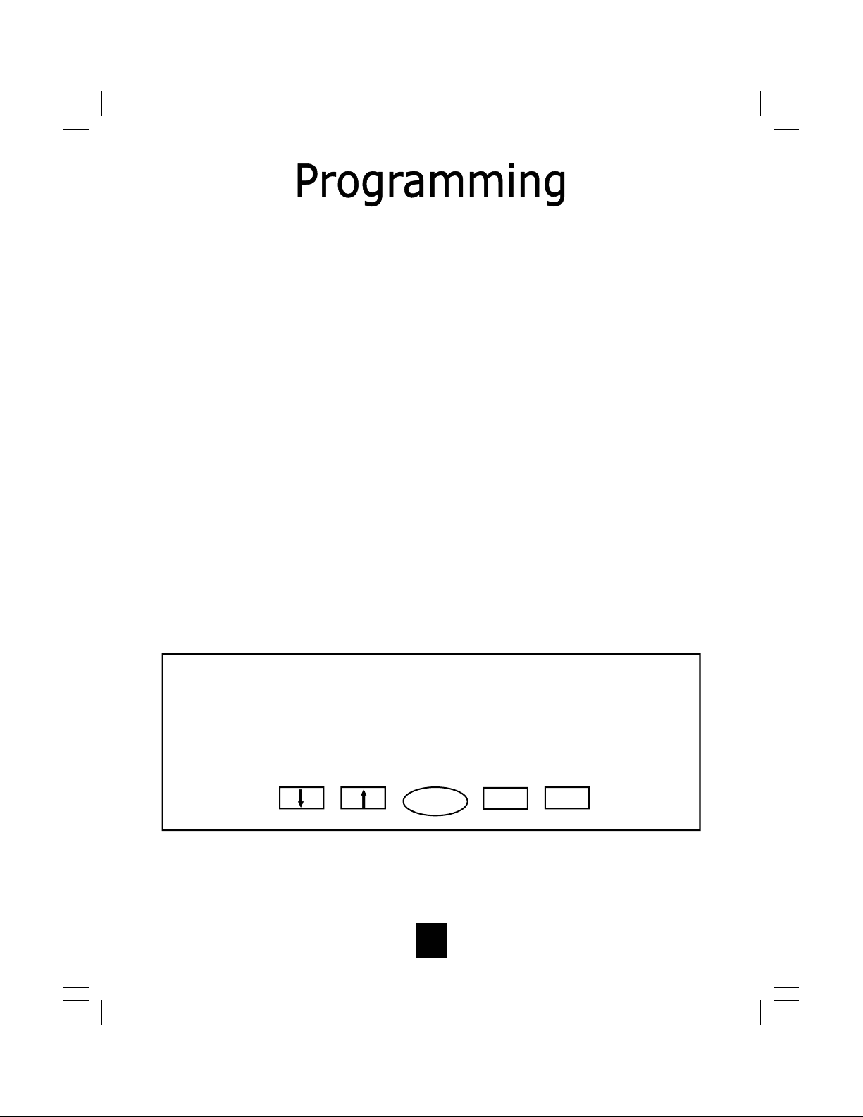
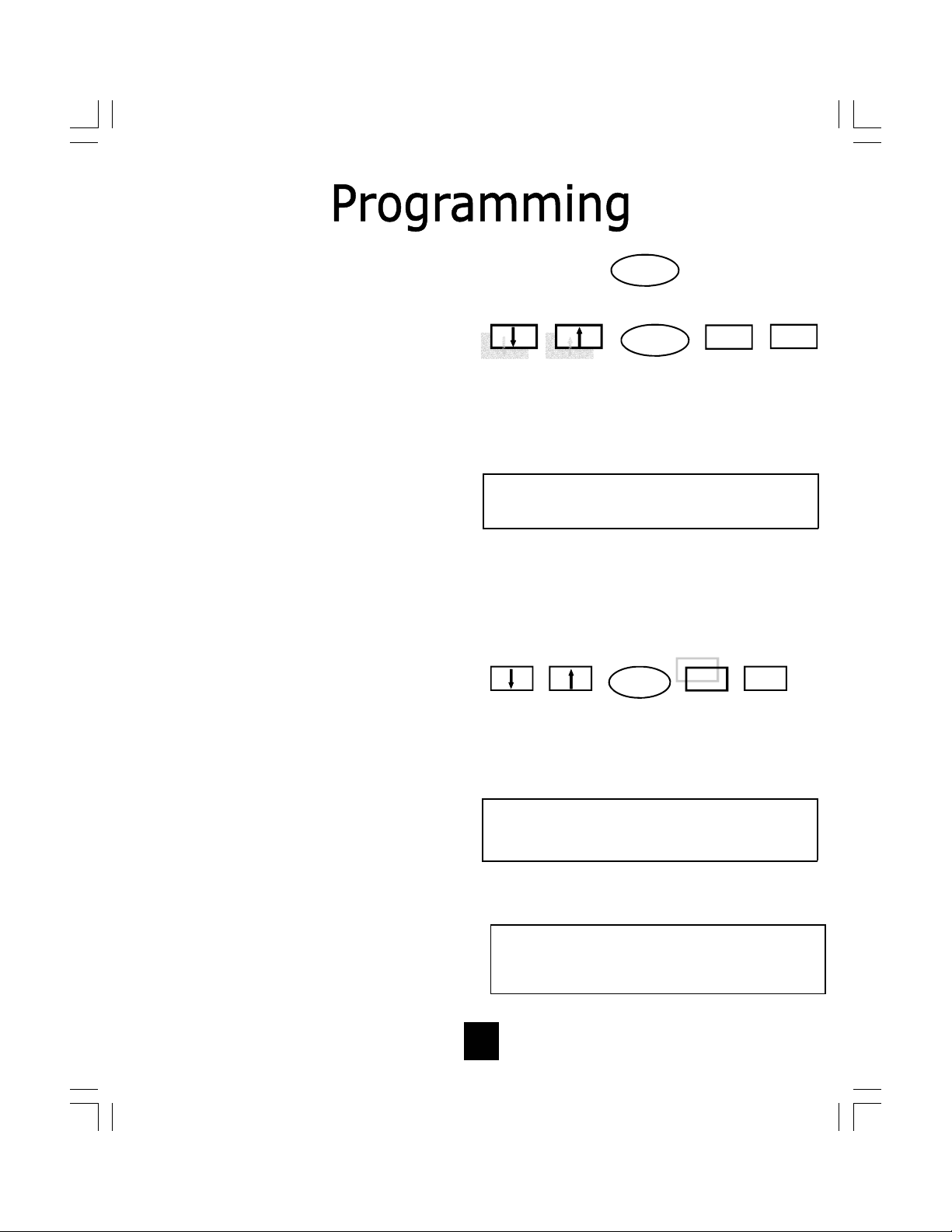
Programming Keys
The Sp ectrum P LUSTM DC-640 s upports the Nor tel Mer idian Digital Centrex
System Environment. The following pages show diagrams on how to program different features of the telephone.
Simply follow the instructions on the LCD screen. The keys below are used to program the
telephone.
PROGRAM KEY (loca t ed on base)
To enter into the programming mode, press the “PROGRAM” key.
EXIT KEY*
To exit the program mode, press the “EXIT” key.
SELECT KEY*
To select the feature needing to be programmed an d advance the LCD screen to the next
screen, press the “SELECT” key.
SAVE KEY*
To save the feature selected, press the “SAVE” key.
ARROW KEYS*
Use the “UP” and “DOWN” keys to scroll through the Programming Menu or Memory Dial
records.
* LCD Display Information Management Keys
The S pectrum PLUS
(LCD) Manage ment Keys that ar e us ed to support pro gramming o f
the telephones and to scroll through the displayed information.
TM
is e quipped wi th f ive L iquid Cr ystal Di splay
Save Select Exit
• Programming must be done with the power adapter plugged into the wall.
• Programming must be performed with the telephone on-hook.
• A maximum of 20 digits can be entered into each memory dial locations, including Pauses.
15
Page 16

Programming Local User Preferences
The S pectrum PLUSTM DC640 re quires simple i nitial pr ogramming th at all ows the
user to personalize the telephone setup.
Quick Program Guide
The Spectrum PLUSTM DC640 Quick Programming Guide is a summary list of set up
options. Additional detailed instructions are provided in the manual.
Programming is initiated by
quickly pressing the
“PROGRAMMING” key.
Set up language
Program 10-Memory
Dialing Numbers
Adjust Ring
Volume Default
Adjust Handset
Volume Default
Adjust Headset
Volume Default
Adjust Speaker
Volume Default
Select the Speaker or
Headset for Answering
Default
Enable/Disable One
Touch Messaging
Enter (PIN) Personal
Identification Number
Seconds to Wait Prior to
PIN dialing
PROG
LANGUAGE?
MEMORY DIAL
NUMBERS?
RING VOLUME?
HANDSET VOLUME?
HEADSET VOLUME?
SPEAKER VOLUME?
DEFAULT ANSWER
DEVICE?
VM ONE-TOUCH
MESSAGING?
VM PIN NUMBER?
VM SECONDS OF WAIT?
Formats Time and Date
Display Options
Set Time and Date
Enable/Disable Keypad
Predialing
Enable/Disable Call Timer
Enable/Disable Speaker
Mute Features
Back to 1st Menu
TIME AND DATE
FORMAT?
TIME AND DATE SET?
PREDIAL?
CALL TIMER?
SPEAKERPHONE MODE
LANGUAGE?
Independent feature keys are pressed to program
these operations;
1. Adjust the LCD Display Contrast by pressing
UP/DOWN key.
2. Store number into memory by pressing the
STORE# key
16
Page 17

Programming Central Office (C.O.) Features
Central Office (C.O.) features must be activated by your local telephone administrator or local telephone company Customer Service Representative. Once this is complete, simply label
the Active Feature Keys to match the programmed C.O. features.
The S pectrum P LUSTM Telephone allow s f orty (40) programmable advanced f eature keys to
interact w ith th e local telephone Dig ital C entrex n etwork. T he c all ou t of th ese k eys h ave
been determined by your local telephone administrator or telephone company Customer Service R epresentative. T he programmin g is done by t he C entral Of fice supporting th e Digi tal
Centrex Environment.
A popular feature of The Spectrum PLUSTM DC640 is Speed Calling. Once it is programmed by
the Central Office, this advanced feature allows you to dial a telephone number using one or
two digits on the keypad. Speed Call/Dialing allows you either 10 one-digit codes (0-9) or up
to 70 two-digit codes (00-69). To find out what code types are available to you contact your
local te lephone a dministrator or C ustomer Service R epresentative. T he dialin g f ormats are
programmed by the Central Office who supports the Digital Centrex Environment.
Programming the Message Waiting (MW) Indicator Light
Programming the Speed Call / Dial Feature Key
Another popu lar S pectrum P LUSTM DC 640 f eature is th e V oice M ail an d M essage W aiting
(MW) Light Indicator. It is a du al function button. On e use is a Message Waiting Indication
indicator that will blink repetitively to indicate that a new message is in the user’s voice mailbox.
The other purpose allows the user to simply press the TouchliteTM button key to connect automatically to their voice mail. When this feature key is programmed properly, the PIN number
dialing is dela yed until a fter th e messaging service requests a pa ssword. Voice Mail ( VM)
requires provisioning at the Central Office but the wait time and PIN are programmed by the
user into the DC640. The Digital Centrex telephone service provider has to activate the voice
mail feature for the light to illuminate and work properly.
Programming O t her System Featu re s
There are man y s ystem featu res th e Di gital C entrex tele phone s ervice offers. T hese are
required to get th e telephone features to f unction. Like most business entities th at use the
Digital C entrex en vironment, th e f eature c hoices are pre-determined an d pre -programmed
into y our telephone n etwork s ystem. Y our loc al t elephone a dministrator or l ocal telephone
company Cu stomer S ervice R epresentative w ill a nswer these questions about your C.O.
services a nd pr ovisioning of th ese features. Th e teleph one w ill in teract w ith th e feature
choices y ou ma ke on ce the pr ogramming is c ompleted w ithin th e te lephone’s n etwork
environment.
17
Page 18

Programming Users Telephone Features
The S pectrum P LUS
user’s preference when operating. The following pages provide instructions on how these
options are programmed.
TM
DC640 al lows f or th e u ser to c ustomize the te lephone to th e
Setting Up Language
The t elephone L CD has the abili ty
to di splay 3 l anguages: English,
French, and Spanish.
1. Press the “PROGRAM” key
(Figure 1 ). Pr ess t he “UP” or
“DOWN” ke y unt il t he d isplay
reads “LANGUAGE?”
(Figure 2).
2. To activate, press the “SELECT”
key (Figure 3).
3. The LCD will display “ENGLISH”.
Press the SAVE key or press the
“UP” or “DOWN” key to
continue . French or Spanish are
the re maining o ptions (Fi gure
4a, 4b, 4c).
4. Press “SAVE” w hen t he co rrect
language is displayed.
5. Press “EXIT” t o exi t the pr ogram mo de or pre ss “ UP” or
“DOWN” t o co ntinue s crolling
through the program mode.
Figure 1
PROGRAM
THEN PRESS
Save Select Exit
Figure 2
L A N G U A G E ?
↓ = P r e v ( S e l e c t ) N e x t = ↑
Figure 3 PRESS SELECT KEY
Figure 4a
L a n g u a g e :
[ E n g l is h ? ] ( S a v e )
Figure 4b
L a n g u a g e :
[ F r a n ć a i s ] ( S a v e )
Figure 4c
DISPLAY WILL READ
Select
Exit
Press SAVE or SELECT to continue
Press SAVE or SELECT to continue
Press SAVE or SELECT to continue
Save
L a n g u a g e :
[ E s p a ñ o l ] ( S a v e )
18
Page 19

Programming the Stored Record Mem ory
The S pectrum P LUS
the LCD memory for frequently dialed calls. This section describes the programming for
the ten ( 10) LCD Memory locations. T hese pr ogrammed numbers w ill be s aved in LC D
Memory.
TM
DC640 allow s for up to ten (10) number records to be s tored in
Programming Location
Memory Records
1. Press the “PROGRAM” key
(Figure 1 ). Pr ess t he “UP” or
“DOWN” ke y unt il t he d isplay
reads “ME MOR Y DIA L
NUMBERS?” (Figure 2).
2. To activate, press the “SELECT”
key (Figure 3).
3. Select a me mory l ocation by
scrolling through the LCD
Display. Enter the number to be
saved. B e sure t o en ter a “1 ”
and area code when required by
your are as te lephone company
(Figure 4).
4. Press “SAVE” to s ave th e
number i n me mory. Note that
the f irst s aved re cord will be
store i n l ocation “M0 ”. Th e second and thi rd r ecords wi ll be
stored i n “M1 ”,
“M2”…”M09”locations (Figure 5).
5. Press “EXIT” t o exit t he p rogram m ode or p ress “ UP” or
“DOWN” t o co ntinue s crolling
through the pr ogram mo de.
(Figure 6)
Figure 1
PROGRAM
THEN PRESS
Save Select Exit
Figure 2
M E M O R Y D I A L N U M B E R S ?
↓ = P r e v ( S e l e c t ) N e x t = ↑
Figure 3
Figure 4
M e m o r y D i a l N u m b e r s :
M 0 : 1 7 1 9 6 3 8 8 8 2 1 ( S a v e )
Figure 5
Figure 6
DISPLAY WILL READ
PRESS SELECT KEY
Exit
ENTER NUMBER TO BE STORED
PRESS SAVE KEY
Exit
PRESS ARROW KEY OR EXIT
Exit
Select
Select
Select
Save
Save
Save
19
Page 20

Programming Volume
(Alerter, Speaker, Headset
or Handset)
1. Press the “PROGRAM” key
(Figure 1 ). P ress t he “UP” or
“DOWN” ke y unt il the display
is on t he co rrect “VOLUME?”
program, i .e. Ri ng, Spe aker,
Headset or Handset (Figure 2).
2. To ac tivate, pr ess the
“SELECT” key (Figure 3).
3. The LCD will display the current
settings. Pr ess t he U P/DOWN
Key to adjust the volume.
4. Press “SAVE” when the correct
volume is displayed.
5. Press “EXIT” to exit the
program mode or press “UP” or
“DOWN” t o c ontinue s crolling
through the program mode.
Figure 2
Figure 1
PROGRAM
THEN PRESS
DISPLAY WILL READ EITHER
R I N G V O L U M E ?
↓ = P r e v ( S e l e c t ) N e x t = ↑
H A N D S E T V O L U M E ?
↓ = P r e v ( S e l e c t ) N e x t = ↑
H E A D S E T V O L U M E ?
↓ = P r e v ( S e l e c t ) N e x t = ↑
S P E A K E R V O L U M E ?
↓ = P r e v ( S e l e c t ) N e x t = ↑
Figure 3
PRESS SELECT KEY
Exit
Select
Save
Save Select Exit
Figure 4a
Press SAVE or SELECT to continue
R i n g V o l u m e :
█ █ █ █ █ █ █ █ █ ( S a v e )
20
Page 21

Programming Default Answer
Device
(Headset or Speaker)
When t he u ser p resses the l ine key ( i.e.
the b ottommost Fe ature K ey) the pho ne
will be r equired to pi ck up o n e ither the
headset or the speakerphone if the handset is on hook. For example, a receptionist might ch oose to au to an swer calls on
a h eadset, w hile s omeone wo rking in a
private o ffice mi ght pr efer the speakerphone. The Default Answer Device Menu
allows the us er to choose be tween the
headset and speakerphone for these scenarios.
1. Press the “PROGRAM” key ( Figure
1). Pr ess t he “UP” or “DOWN” ke y
until t he d isplay sh ows “DEFAULT
ANSWER DEVICE?” (Figure 2).
2. T o a ctivate, press the “SELECT” key
(Figure 3).
3. Select e ither “HEA DSET” or
“SPEAKER”. Th is activates wh ether
the HE ADSET or SP EAKER is the primary an swering d evice. By s electing
SPEAKER the pr imary answer d evice
includes the handse t and speaker
(Figure 4a, 4b).
.
4. Press “SAVE” w hen t he c orrect d e-
fault is displayed.
5. Press “EXIT” to exi t the pro gram
mode or p ress “ UP” o r “DOWN” to
continue scrolling through the
program mode.
Figure 1
PROGRAM
THEN PRESS
Save Select Exit
Figure 2
D E F A U L T A N S W E R D E V I C E ?
↓ = P r e v ( S e l e c t ) N e x t = ↑
Figure 3
Figure 4a
D e f a u l t A n s w e r D e v i c e :
[ H e a d s e t ] ( S a v e )
Figure 4b
D e f a u l t A n s w e r D e v i c e :
[ S p e a k e r ] ( S a v e )
DISPLAY WILL READ
PRESS SELECT KEY
Exit
Press SAVE or SELECT to continue
Press SAVE or SELECT to continue
Select
Save
21
Page 22
Programming Voice Mail
Using the O ne-Touch Mes saging f eature, t he V oice M ail a dvanced feature
key c an b e pre ssed to c onnect to the
Voicemail system on the Nortel Meridian
PBX or Central Office switch. The switch
must b e pr ovisioned f or vo ice m ail o n
the 12th key.
The pro gram al lows for up to 20-digits.
The di gits o f th e P ersonal Identification
Number (PIN) will appear on the LCD as
they are e ntered, but will not appe ar
after the y are saved. The VM Pi n Number menu will show an asterisk in place
of each digit.
The VM P IN Nu mber Menu will appear
only if t he O ne-Touch Me ssaging fe ature is enabled.
The VM Seconds o f Wait menu will also
appear only if the One-Touch Messaging
feature is e nabled. T his is t he a mount
of ti me that the t elephone wai ts whe n
the Vo icemail ke y i s pr essed and wh en
the PIN Number is dialed.
1. Press the “PROGRAM” key (Figure 1). Press
the “UP” or “DOWN” k ey until the display
shows “VM ONE TOUCH MESSAG-
ING?” (Figure 2).
2. To activate, press the “SELECT” key (Figure
3).
3. Select ei ther “ENABLED” or “DISABLED”. Selecting E NABLE activates One Touch Messaging (Figure 4a, 4b).
Note: If feature key number 12 is provisioned in the
DMS a s t he vo ice ma il key, pressing t he ke y w ill
activate v oicemail regardless i f one-touch m essaging is enabled o r not. Howe ver, w hen o ne-touch
messaging is enab led, t he P IN n umber will a lways
be dialed. The PIN number can be left blank (nonprogrammed).
4. Press “SAVE” w hen the c orrect default is
displayed.
Figure 1
PROGRAM
THEN PRESS
Save Select Exit
Figure 2
V M O N E T O U C H M E S S A G I N G ?
↓ = P r e v ( S e l e c t ) N e x t = ↑
Figure 3
Figure 4a
V M O n e T o u c h M e s s a g i n g :
[ E n a b l ed ] ( S a v e )
Figure4b
V M O n e T o u c h M e s s a g i n g :
[ D i s a b l ed ] ( S a v e )
DISPLAY WILL READ
PRESS SELECT KEY
Exit
Press SAVE or SELECT to continue
Press SAVE or SELECT to continue
Select
Save
22
Page 23

Programming Voice Mail:
Seconds of Wait and
PIN Number
1. Once t he V OICE MA IL “VM ONE
TOUCH MESSAGING?” i s
ENABLED, p ress t he “UP” or
“DOWN” key to ge t the sub m enu.
“VM PIN NUMBER:” (Figure 1).
2. Press SELECT (Figure 2).
3. Enter yo ur p ersonal i dentification
number (P IN) that wi ll be u sed to
retrieve your v oice m ail m essages.
In p rogramming mo de, the PIN
number wi ll be s hown but o nce
saved, t he P IN wi ll b e sh own a s
asterisks (Figure 3).
4. Press SAVE (Figure 4).
5. Press the “UP” or “DOWN” ke y to
display “VM Second of Wait”.
Seconds of Wait allows for a 0 to 99
second ti med d elay be fore the
telephone me mory wi ll dial the preprogrammed p ersonal i dentification
number (PIN) (Figure 5). The timing
will ne ed to b e tes ted wi th the
specific v oice mail service to ensure
the c orrect am ount of se conds i s
programmed. T he ti med de lay to
program i nto me mory i s de pendent
on when the voice mail answers and
requests a PIN number. To
determine thi s t ime, make a t rial
call to yo ur Voice Mail and t ime the
voice mail service.
6. Press t he S ELECT key ( Figure 2 ).
Enter the number of seconds to wait
using the ke ypad. Th e numbe r will
be displayed on the LCD. The range
is 0—99 seconds (Figure 6).
7. Press “SAVE”.
Figure 1
V M P I N N U M B E R ?
↓ = P r e v ( S e l e c t ) N e x t = ↑
Figure 2
Figure 3
V M P I N N u m b e r ?
* * * * * *
V M P I N N u m b e r ?
1 2 3 4 5 6
Figure 4
Figure 5
V M S E C O N D S O F W A I T ?
↓ = P r e v ( S e l e c t ) N e x t = ↑
Figure 6
V M S e c o n d s o f W a I t
9 0 S e c o n d s (S a v e)
DISPLAY WILL READ
PRESS SELECT KEY
Exit
DISPLAY WILL READ *, ENTER PIN
PRESS SAVE KEY
Exit
DISPLAY WILL READ
PRESS SELECT, ENTER SECONDS
Select
Select
Save
Save
23
Page 24

Programming Time
and Date
1. Press the “PROGRAM” key
(Figure 1 ). P ress t he “UP” or
“DOWN” key until the display
shows “TIME AND DATE
FORMAT?” (Figure 2).
2. To ac tivate, pr ess the
“SELECT” key (Figure 3).
3. There are six different format
options (Fi gure 4) plus th e
option to di sable ti me and
date.
4. When the desired format is
displayed o n the L CD s creen,
press the “SAVE” key.
5. By pressing “UP”, t he screen
“TIME AND DATE SET?” will
appear (Figure 5).
6. Press “SELECT”.
7. E nter the Date and Time. Time
can be entered as a 12-hour or
24-hour c lock. I n the 12-ho ur
format, pr ess 2 fo r “AM” o r 7
for “PM” (Figure 6).
8. Press “EXIT” to exi t the p rogram m ode or pre ss “UP” or
“DOWN” to co ntinue s crolling
through the program mode.
Figure 1
PROGRAM
THEN PRESS
Save Select Exit
Figure 2
T I M E A N D D A T E F O R M A T ?
↓ = P r e v ( S e l e c t ) N e x t = ↑
Figure 3
Figure 4
MMM DD hh:mm = JAN 01 08:00 24 Hour
DD MMM hh:mm = 01 JAN 08:00 24-Hour
MM/DD/YY hh:mmA = 01/01/03 08:00A 12-Hour
DD/MM/YY hh:mmA = 01/01/03 08:00A 12-Hour
MMM DD hh:mmA = JAN 01 08:00A 12-Hour
DD MMM hh:mmA = 01 JAN 08:00A 12-Hour
Figure 5
T I M E A N D D A T E S E T ?
↓ = P r e v ( S e l e c t ) N e x t = ↑
DISPLAY WILL READ
PRESS SELECT KEY
Exit
SELECT DESIRED FORMAT, ENTER SAVE
PRESS NEXT THE DISPLAY WILL READ
Select
Save
Default format is MMM DD hh:mm
or JAN 01 08:00
Figure 6
ENTER DATE AND TIME
T i m e a n d D a t e S e t :
M M D D Y Y h h:m m A (S a v e)
24
Page 25

Programming Pre-dial
When Pr e-dial is en abled, t he
keypad can be used to dial while
the telephone is ON HOOK. After
pre-dialing, li ft the hands et, or
press t he sp eaker key, or p ress
the he adset key wi thin 12 s econds to place the outgoing call.
1. Press the “PROGRAM” key
(Figure 1). Press the “UP” or
“DOWN” key until the display
shows “PREDIAL?” (Figure
2).
2. Press the “SELE CT” key
(Figure 3).
3. Enable will be displayed on the
LCD. P ress “SAVE” to e nable
pre-dial. T o di sable pre-dial,
follow t he sa me p rocedure
(Figure 4).
4. Press “EXIT” to exit the pro gram m ode o r pr ess “ UP” o r
“DOWN” t o continue s crolling
through the program mode.
Figure 1
PROGRAM
THEN PRESS
Figure 2
DISPLAY WILL READ
P R E D I A L ?
↓ = P r e v ( S e l e c t ) N e x t = ↑
Figure 3
Figure 4
PRESS SELECT KEY
Exit
DISPLAY WILL READ
Select
P R E D I A L :
Save Select Exit
Save
[ E n a b l e d ] ( S a v e )
25
Page 26

Programming Call Timer
When Call Timer is enabled, the
LCD w ill di splay t he el apsed
time of an active call when the
primary di rectory numbe r i s
used.
1. Press the “PROGRAM” key
(Figure 1). Press the “UP” or
“DOWN” k ey until th e di splay sh ows “CALL
TIMER?” (Figure 2).
2. Press the “SELECT” key
(Figure 3).
3. Enable will be displayed on the
LCD. Press “SAVE” to e nable
Call Timer.
4. Press “EXIT” to exit the
program mo de or pr ess “ UP”
or “DOWN” to continue scroll-
ing thr ough th e p rogram
mode.
Figure 1
Figure 2
C A L L T I M E R ?
↓ = P r e v ( S e l e c t ) N e x t = ↑
Figure 3
Figure 4
PROGRAM
THEN PRESS
DISPLAY WILL READ
PRESS SELECT KEY
Exit
DISPLAY WILL READ
Select
Save Select Exit
Save
C a l l T i m e r ?
[ E n a b l e ] ( S a v e )
26
Page 27

Programming Speakerphone Mode
The DC640 includes an option for 2-way Speakerphone or Monitor Mode.
When “MONITOR MODE” is enabled, voice transmission automatically stops
when the speakerphone key is pressed. MUTE will activate and the LED indica-
tor will illuminate when the speakerphone is turned on through the SPEAKER
key, or the LINE key, or from an incoming Intercom call. The MUTE feature will
activate when the user switches from the handset or headset to the speakerphone during an active call.
When “MONITOR MODE” is enabled, the MUTE feature can be turned OFF to
enable voice transmission on the speakerphone by pressing the MUTE key.
If the di rectory number s are switched or a call is pl aced o n h old and the n
released, the MUTE feature will be reactivated.
The “ 2-WAY SPEAKERPHONE” option all ows the voice to go out a utomati-
cally to the speaker without muting voice transmission.
1. Press the “PROGRAM”
key ( Figure 1 ). Then,
press t he “UP” or
“DOWN” ke y u ntil t he
display sh ows
“SPEAKERPHONE
MODE?”
(Figure 2).
2. Press the “SELECT” key
(Figure 3).
3. Select 2-way Speakerphone to a ctivate the
speaker o r sel ect M onitor
Mode to mute the speaker.
Press “SAVE” (Figure 4).
4. Press “EXIT” to exit the
program mo de or p ress
“UP” o r “DOWN” t o co n-
tinue s crolling thr ough the
program mode.
Figure 1
PROGRAM
THEN PRESS
Figure 2
DISPLAY WILL READ
S P E A K E R P H O N E M O D E ?
↓ = P r e v ( S e l e c t ) N e x t = ↑
Figure 3
Figure 4a
PRESS SELECT KEY
Exit
DISPLAY WILL READ
Select
S p e a k e r p h o n e M o d e :
[ 2-w a y S p k r p h o n e ] ( S a v e )
Figure 4b
DISPLAY WILL READ
S p e a k e r p h o n e M o d e :
[ M o n i t o r M o d e ] ( S a v e )
Save Select Exit
Save
27
Page 28

LCD FEATURES
The S pectrum PLU STM LCD d isplay is a 2 -lines x
24-character backlit display with con trast adjustments. The LCD w ill display t he i dentity of the
caller a nd t he t ime of t he ca ll. Th e u ser h as t he
option to answer the call or allow the call to automatically be forwarded to voice mail.
LCD BACKLIGHT FEATURE
The S pectrum PLUSTM i s e quipped wi th a bl ue
backlit Liquid Crystal Display (LCD) that enhances
the visibility of the LCD.
LCD DISPLAY INFORMATION
The L CD d isplays information t hat is p rovided b y
the Nortel Meridian PBX or Central Office.
Information t hat is dis played o n t he L CD is
provided by the P BX or C entral O ffice. T he L CD
will display this information when an incoming call
comes in
.
28
Page 29

Caller Identification (Caller ID) LCD Display Adjustments
LCD TILT ANGLE FEATURE
The LCD can b e t ilted u pward for
direct vi ewing and e asy reading.
Tilt the LCD to the desired position
by lifting up the back of LCD housing (Figure 1).
(60° maximum upward tilt).
LCD CONTRAST FEATURE
(16-step)
The LCD c haracters can be l ightened or d arkened u sing t he c ontrast UP/DOWN keys (Figure 2).
While the hands et i s i n the O N
HOOK position, simply press the UP
or DO WN ke ys to adjust th e contrast of the LCD screen. T here are
16 contrast st ep a djustments
(Figure 3).
To l ighten c haracters, pre ss the
“UP” key.
To darker c haracters, pr ess the
“DOWN” key.
The display will clear 3 seconds
after the last key press or after
pressing the EXIT key.
Figure 2
Figure 3
C O N T R A S T
█ █ █ █ █ █ █ █ █
PRESS THE UP OR DOWN KEYS
Save Select Exit
29
Page 30

MEMORY DIAL KEY
The M emory D ial key a llows a ccess t o t he Memory for p rogrammed n umbers.
Toggle be tween di fferent Me mory Di al numbe rs wh en pre ssing the Me mory Dial
key, the “UP” or “DOWN” keys, or the dial pad keys. When the memory location is
found, go off hoo k by li fting t he hands et or pr essing the H eadset O n/Off or
Speaker keys within 12-seconds to activate that memory dial number.
Retrieving and Dialing Stored Memory Records
1. Press the “MEMORY” key (Figure 1).
Figure 1
2. Press the “UP” or “DOWN” key until the display reads the number or memory
location wanted or press the numeric location using the keypad (Figure 2).
Figure 2
PRESS UP or DOWN KEY
3. To activate
Exit
Select
Save
Figure 2
M e m o r y D i a l N u m b e r s :
M 0 : 1 7 1 9 6 3 8 8 8 2 1
SEARCH FOR MEMORY LOCATION
dialing, lift the handset,
or press the “SPEAKER” key or
Figure 3
“HEADSET ON/OFF” key (Figure 3).
MEMORY
Deleting/Changing a Stored Memory Record
To d elete or change a stored m emory location, p ress “PROGRAM”, and scr oll t o
“MEMORY DIAL NUMBER?”. Use the UP/DOWN keys to find the record to delete.
When found, p ress “SELECT”, t hen “S AVE” t o delete t he n umber. To save a n ew
number i n a me mory l ocation, s croll to that location, pre ss “S ELECT”, the n enter
the new number. To save the new number, press “SAVE” and then press “EXIT”. To
avoid deleting the record, press the “EXIT” key PRIOR to entering a new number.
30
Page 31

Headset Feature
The Sp ectrum PLUS
separate por t f or pl ugging in an o ptional
headset. T he p ort i s l ocated on the
bottom of the ba se un it. T he T eleMatrix
FreeSpeech
TM
TeleMatrix feature that allows the user the
freedom t o t oggle b etween t he h eadset,
handset and speakerphone mo des dur ing
a conversation.
When th e “HEADSET ON/OFF” ke y is
ON, pressing the “SPEAKER” key will ac-
tivate the s peaker an d di sconnect the
headset li ne auto matically. Thi s fe ature
avoids hav ing to us e the hoo k switch/
handset t o p rocess t elephone c alls whil e
in headset mode.
The headset can be purchased from a
TeleMatrix di stributor. T here a re many
varieties of headset models available.
TM
is e quipped wi th a
Talk Feature is a uni que
!
NOTE: When using a directconnect headset, an external amplifier is NOT recommended because the phone has a built in
amplifier.
Installing a Headset
• The headset port is located on the bot-
tom side of the telephone base.
• Plug the mo dular end of th e h eadset
cord i nto the mo dular por t o f the
telephone l abeled “HEADSE T” (f igure
1).
• Press the “HEADSET ON/OFF” key to
activate the he adset. The L ED ab ove
the key wi ll illuminate to i ndicate that
the headset is on (figure 2).
31
Figure 1
Figure 2
Page 32

Using A Headset
The “HEADSET ON/OFF” ke y c ontrols the ac tivation o f the He adset.
When usi ng the headset feature, th e hand set rem ains on-hook at all
times.
Placing/Answering a Call
using the Headset On/Off Fea ture
• To answer an incoming call, press the “HEADSET ON/OFF” key to activate
the headset. The LED above the “HEADSET ON/OFF” key will be illuminated
when in ON position.
• Adjust the volume, if necessary.
• Use the control features of the headset that are available to you.
• You can dial using the keypad or a provisioned advance feature key.
• To end he adset a ctivation, pre ss the “HEADSET ON/OFF” ke y. The LED
above the “HE ADSET ON/OFF” key will not be lighted when in OFF position.
Volume Lock Feature — When the hands et, sp eaker, ring er or
headset volume is adjusted, the volume will automatically stay at
f
that setting in the next use.
FreeSpeechTM Talk Feature is a unique TeleMatrix feature that
allows the user the freedom to toggle between the headset,
f
handset and speakerphone modes during a conv ersation.
32
Page 33

PREDIALING FEATURE
When p rogrammed, th e t elephone supports a pre -dialing f eature f or c alls
made on the Primary Directory Number, or the line corresponding to Feature
Key 1 (directly above the Speaker key). The pre-dial feature all ows u sers to
enter a number b efore li fting the hands et or using the he adset or speakerphone for an outgoing call. The user can enter up to 20-di gits, which are dialed i f t he u ser l ifts t he h andset or p resses t he Headset On/Off or Speaker
keys within 12-seconds of dialing the last digit.
RELEASE KEY FEATURE
The “RLS” ( RELEASE) key i s a h ard l ine b reak. Wh en p ressed t he ke y
automatically di sconnects an e xisting ac tive li ne. T here i s no di al to ne af ter
the “RLS” key is pressed.
To use, simply press the “RLS” key when a conversation is complete.
VOLUME CONTRO L
(Ring, Speaker, Headset, Handset)
The SpectrumPLUS
control located on the front of the phone.
To adjus t the v olume, press the r ight e nd of the “VOLUME” key and t he
volume is increased. When the left end of the “VOLUME” key is pressed, the
volume is decreased.
The “VOLUME” key is a sixteen-step volume control.
TM
DC-550 is equipped with an ADA/FCC compliant volume
33
Page 34

SPEAKERPHONE FEATURE
The S pectrum PLUS
high qua lity hal f-duplex s peakerphone
feature to allow for hands-free operation.
To use, simply press the “SPEAKER” key
when placing or answering a call. The primary directory line will activate automatically.
The LED ab ove the “SPEAKER” key w ill
illuminate to i ndicate that the speakerphone is in-use.
To d isconnect, simply p ress t he
“SPEAKER” key or “RLS” key.
TM
is e quipped wi th a
Note: Use the VOLUME
BAR to adjust the volume
of the speaker.
Note: Use the MUTE key
during conference calls to
reduce background noise.
POWER FAILURE
During an y pow er fai lure on ly two f eature key L ED’s will wor k. They ar e
keys one and two in the first row of keys.
34
Page 35

HOLD FEATURE
The “HOLD” k ey i s u sed t o p lace a caller on
hold. To use, simply press the “HOLD” key.
When t he “HOLD” key is a ctive, t he handset
can b e l ifted off- hook or returned t o i ts on hook pos ition and the l ine wi ll no t be
disconnected. T o return t o t he caller, si mply
lift t he hands et or ac tivate the s peaker key
and press the blinking line key .
STORE FEATURE
The DC640 has a Store feature which allows a
user t o store a di aled numbe r of up t o 20digits be fore hangi ng up dur ing a c onversation. Af terwards, th e s tored numbe r will be
retrieved i f t he u ser p resses t he STORE key
while in the Idle state. The stored digits would
then po pulate the f irst line and be tre ated i n
the same manner as pre-dialed digits.
Although the user will only be able to pre-dial
or us e the s tored di gits f or c alls o n the
Primary D irectory N umber, he or she w ill be
able to store di gits dial ed o n any o utgoing
line.
35
Page 36

MUTE FEATURE
A “MUTE” key is p rovided t o a llow
privacy dur ing a ba ckground conver-
sation. When the “MUTE” key is acti-
vated, the mi crophones i n the handset, speakerphone and/o r headset are
disabled. Wh en t he “MUTE” key i s
activated, the par ty on the o ther end
of the line will not hear voice. To de-
activate, press the “MUTE” key again.
Note: i f the mute feature is automatically ac tivated each t ime t he speakerphone i s en abled,
the phone may be configured in monitor mode.
PAUSE KEY FEATURE
A “PAUSE” key is provided to insert a
1.0-second ti me bre ak whe n di aling
from the keypad or memory location.
A mul tiple o f “PAUSE” keys can b e
dialed or programmed into memory of
a caller record.
Each pause key counts as one (1) digit
when p rogrammed i nto m emory.
When pro gramming i nto me mory or
dialing, s imply pre ss the pause key in
the appropriate dialing pattern.
36
Page 37

Business Feature Keys
Advanced feature ke ys a re pr ogrammed b y your T elephone S ystem Ad ministrator or
Telephone Service P ersonnel. T hese f eatures are provided by t he t elephone company i n a
Nortel Digital Centrex environment. Only some of the features listed will be available to you
because each telephone is customized to a specific business application.
Auto Callback Activates the Camp-On feature. Allows the attendant to extend an incoming call
Auto Dial Autodial feature permits an attendant to dial frequently called numbers by press-
Auto Line Provides an automatic connection between a calling station that goes off-hook
Call Fwd Activates the Call Forward feature that is provisioned in the Central Office.
Call Park Activates the Call Park feature. Allows the user to park a call.
Call Wait Activates the Call Waiting feature. An audible signal is heard when the phone is
Conf Activates the 3-way Conference feature.
Conf 3 Similar to Conf, but with a maximum of 3 ports.
Conf 6 Similar to Conf, but with a maximum of 6 ports.
Conf/Transfer Activates the 3-way Conferencing/Transfer feature.
Cwt Cancel Allows a station user to prevent, on a per-call basis, any incoming calls from call
DND Do Not Disturb. Also see Make Busy.
Dir Pickup Permits a station to answer a call that is ringing any line within an assigned
Drop Allows user to drop a call on hold. Suggest to use the Release Key.
End-to-End Activates the End to End feature.
Hunt Activates the hunting features. Hunting increases likelihood of the call being re-
I/C Activates Intercom feature (to a specific station).
I/C Group Activates Intercom Group feature (to a group of stations).
Inspect Allows user access to information about the set’s assigned features and incoming
Leave Msg Allows the user to leave or retrieve messages.
Make Busy Allows for the set to be made busy to incoming calls. Can use the DND label.
Override Activates the Busy Override feature. Allows set to gain access to a busy station.
Page Activates the Page feature for getting access to a loudspeaker paging system.
Pickup Activates the Call Pickup feature to allow a station to pick up a call.
Pwr Features Multiple features adds a variety of C.O. provisioning services.
Privacy Activates the Privacy feature.
Priv Rls Deactivates the Privacy feature.
Query Busy Allows a stations to query the busy/idle status of one designated station within a
Redial Activates the Redial feature to allow for last called number dialing.
to a busy station and the caller the option of continuing to wait.
ing the Autodial feature key.
and a predetermined location.
in-use.
waiting.
group.
ceive within an assigned group.
calls.
group.
Note: Preprinted labels with the above featured names were provided in the original box.
37
Page 38

ACD Call Cente r Fe ature Keys
Agent Allows ACD Supervisor to select the Agent to call when using the Call Agent fea-
Agent Avail Allows the ACD Supervisor to require an Agent to receive available incoming
Agt Status Allows supervisor to monitor an Agent's status. Recommend Display Queue
Ans Agent Allows supervisor to receive a ring back when a Agent is calling the Supervisor.
Ans Emergency Allows supervisor to immediately answer emergency calls from Agents who have
Call Agent Allows supervisor to call an Agent directly.
Call Supv Allows the Agent to call the Supervisor directly.
Dis Agt Sum Allows supervisor to view Agent activity in ACD group.
Disp Queue Allows supervisor or Agent to view ACD queue status.
EMK Allows Agent to immediately conference and/or record abusive calls.
Emergency Same as EMK. Reports an abusive or threatening call to supervisor.
Flex Call Allows deactivation of conference caller to smaller group.
Force Call Can also use the Release key.
In Calls Allows Agent to answer Primary Directory calls using the first key on the set.
Interflow Allows Supervisor to reroute incoming calls from one ACD group to another.
LOB Agent enters a three (3) digit code to record the nature of the call for line of
MCH Activates the "Malicious Call Hold" feature.
Night Serv Allows supervisor to enable or disable Night Service handling.
Not Ready Allow agent to follow up on a transaction without being interrupted by the next
Obs Agent Allows supervisor to monitor a conversation between an Agent and an ACD caller.
Park Activates the Call Park feature.
Pwr Features Multiple features adds a variety of C.O. provisioning services.
Queue Prioritizes incoming calls in a queue by order of arrival.
Queue Status Allows Supervisor to monitor the queue status of an ACD group.
Supervisor Allows Agent to select a supervisor to call.
Transfer Activates the Call Transfer feature.
ture or enables the ACD Supervisor to check the status of all ACD Agent positions
when using the Display Agent Feature.
calls, even though the Agent has pressed the Not Ready key.
Status.
the Emergency key.
business reporting.
call.
Note: Preprinted labels with the above featured names were provided in the original box.
38
Page 39

Keep the telephone dry. If it gets wet on the outside,
wipe it dry immediately. Liquids might contain minerals
that can corrode the electronic circuits. Do not touch the
unit if submerged in water. Call for assistance.
Use and store the telephone only in normal temperature
environments. Temperature e xtremes ca n s horten t he
life of electronic devices, damage batteries, and distort
or melt plastic parts. Avoid direct sunlight.
Keep the t elephone a way f rom excessive dus t and di rt
that can cause premature wear of parts.
Wipe the te lephone with a damp c loth o ccasionally to
keep i t looking new. Do not use harsh chemicals, cleaning solvents, or strong detergents to clean the unit.
39
Page 40

When p roblems ar ise during installation o r s ervice t hat c annot be
resolved using this or related documents, contact the TeleMatrix Priority Car e D epartment, Monday thro ugh Fr iday, 8:30a. m. - 4:30p. m.
MST:
Toll Free: 1-800-462-9446
Direct: 719-638-8821
Fax: 719-638-8815
www.te lematrixusa.com
Many t imes a p roblem is e ither in stallation o r u ser r elated. P lease
contact TeleMatrix PRIOR to sending a telephone to our service center
for repair. In the unlikely event that a factory repair is necessary:
1. Include a br ief description o f the p roblem that you are
exp eriencing.
2. Include a proof of purchase for a repair under warranty.
3. Send the telephone prepaid by UPS or Parcel Post, insured to:
T eleMatrix, Inc.
Priority Care Center
5025 Galley Road
Colorado Springs, Colorado 80915
TeleMatrix will pay r eturn po stage on the re paired te lephone. All ow
2-3 weeks for delivery. When immediate replacement is required, see
our FastLane
SM
replacement policy on our internet site.
40
40
Page 41

STATEMENT OF LIMITED WARRANTY
TeleMatrix, Inc. (TMX) warrants to its [original end customer] [purchaser] that Spectrum and Marquis
randed p roducts manufactured by TMX ar e fr ee fr om d efects in ma terials and workmanship for
b
(5) years, and Spectrum PLUS for (2) years after the date of purchase, and Regency branded products
manufactured by T MX are free from defects i n materials and workmanship f or (3) years, other than
the fo
llowing products for which the warranty period shall be one (1) year: handset batteries, either
NiCd or NiMH, used in TMX cordless products. If a product fails this warranty during the warranty
period, TMX will, at its o ption, either repair o r r eplace the d efective p roduct o r p arts, o r d eliver
replacements for de fective products o r parts on an exchange basis a t no additional ch arge to the
customer e xcept a s set forth bel ow. Repair pa rts or r eplacement p roducts may be ei ther n ew o r
reconditioned. Products or parts returned to TMX under this warranty will become the property of
TMX. War ranties on products r epaired by TM X e xpire at t he te rmination of the or iginal w arranty
period.
This limited warranty does not cover:
1. Products or parts which are damaged, abused or misused;
2. Any damage resulting from improper installation, maintenance or operation of the product;
3. Damage resu lting fr om unauthorized modification or re pair of the pr oduct, or f rom im-
proper connection of the product to other equipment;
4. Cords, connectors and replaceable batteries;
5. Damage in transit to the TMX repair facility;
6. Any product or part unless proof of date of purchase is submitted with the product when
returned for warranty repair; or
7. Costs incurred by the customer in removing and shipping the product to TMX for repair or
replacement, and costs of reinstallation of the product.
8. Products or parts which are not owned and used by the original end user customer.
The cost and risk of loss or damage for sending the product to TMX will be borne by the customer.
TMX EX PRESSLY DISCLAIMS A LL W ARRANTIES EX CEPT THE L IMITED W ARRANTY SET FO RTH
HEREIN, WHICH IS T HE SOLE A ND EXCLUSIVE W ARRANTY O F THE PRODUCT, AND IS IN L IEU OF
ALL OTHER WARRANTIES, WHETHER ORAL OR WRITTEN, EXPRESS OR IMPLIED, OR STATUTORY.
THERE A RE N O IMPLIED W ARRANTIES OF MERC HANTABILITY OR FI TNESS FOR A PA RTICULAR
PURPOSE. THE CUSTOMER’S SOLE REMEDY UNDER THE TMX WARRANTY SHALL BE REPAIR OR REPLACEMENT AS P ROVIDED ABOVE. IN NO E VENT W ILL T MX BE L IABLE T O C USTOMER O R ANY
OTHER PARTY FO R AN Y I NDIRECT,INCIDENTAL OR CO NSEQUENTIAL DAMAGES, I NCLUDING,
WITHOUT L IMITATION, DAMAGES O F L OST PROFITS, LOST REVENUES, L OSS OF USE OF FACILITIES OR EQUIPMENT, OR COST OF SUBSTITUTE EQUIPMENT ARISING OUT OF THE USE OR INABILITY TO USE THIS PRODUCT, EVEN IF THE CUSTOMER HAS ADVISED TMX OF THE POSSIBILITY OF
SUCH DAMAGES. TMX LIABILITY FOR DAMAGES SHALL NOT EXCEED THE PURCHASE PRICE OF THE
DEFECTIVE PRODUCT.
This limite d w arranty is n on-transferable w ithout the p rior written ap proval of TMX . It g ives the
customer s pecific le gal rights. The c ustomer may have other rights which v ary und er lo cal law .
Some jur isdictions may no t a llow limitatio ns o n the te rm of an imp lied warranty or e xclusions or
limitations of incidental or consequential damages.
41
Page 42

 Loading...