

Page 1
INSTALLATION
AND USER GUIDE
®
TeleMatrix Copyright 2005 ©
2802MWD5
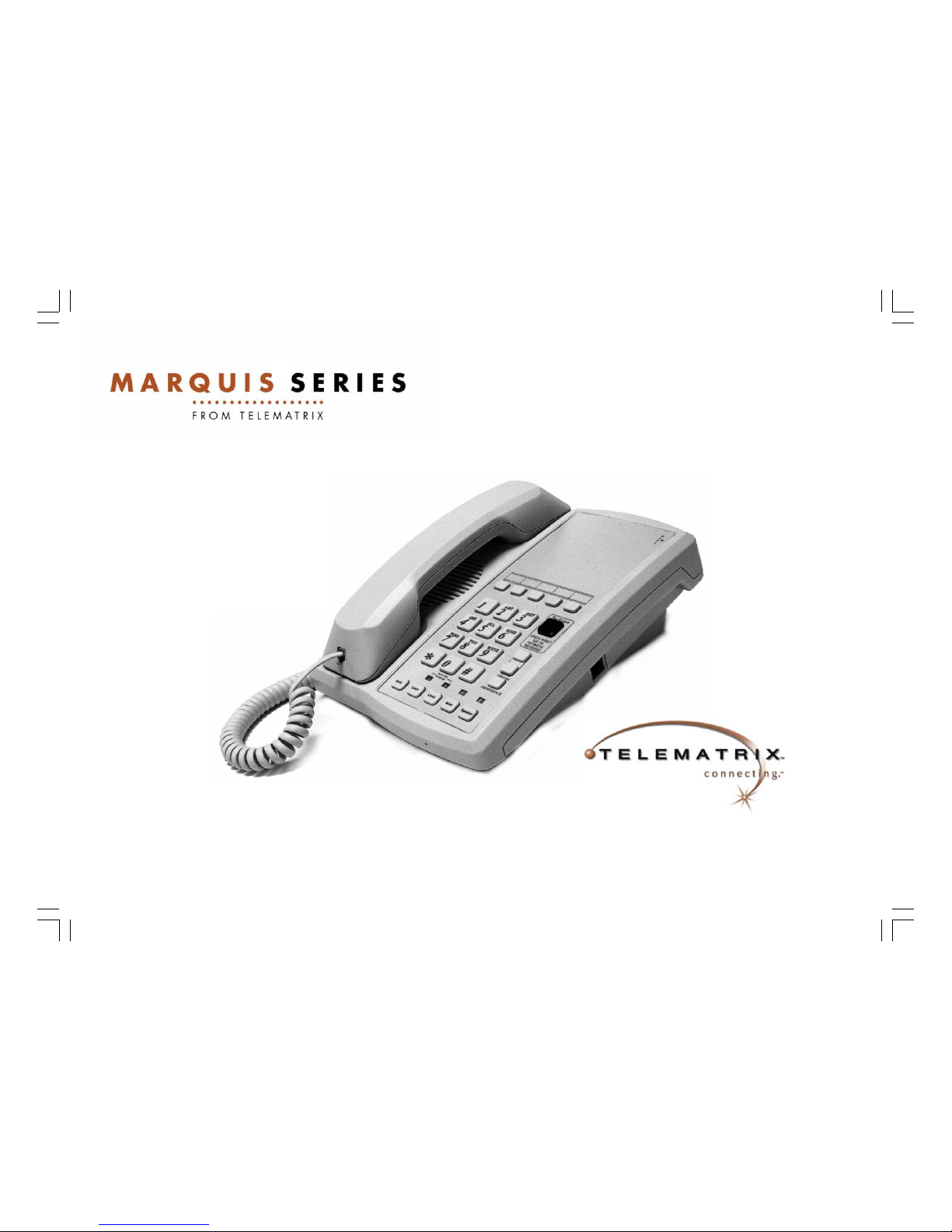
TWO LINE
DELUXE FEATURE
TELEPHONE
Page 2

COMPLIANCE AND SAFETY
As specified by FCC regulation, we are required to inform you of specific governmental and compliance
regulatory requirements, safety notices, safety instructions and other informative information. TeleMatrix, Inc. provides this information in a separate manual. We pack the separate Compliance and Safety
Manual within each outer box or product box when shipped.
Prior to reading this operation manual and prior to setting up your telephone, please refer to the Compliance and Safety Manual.
If the Compliance and Safety Manual is not i mmediately available. Please obta in a free copy by calling
our Priority Care Department (phone number 1-800-462-9446) or by downloading a copy on our Internet
(web site address www.telematrixusa.com ).
Page 3

Features ...........................................………..……………………………………................................... 1
Controls ...........................................................................……………………………………………….. 2
Installation .....................................................................……………………………………………........ 4
Switch Settings .....................................….......................……………………………………………...... 6
Wall Mounting .....................................….......................……………………………………………........ 7
Programming Speed Dial Memory .................................……………………………………………....... 8
Programming The TouchLite™Feature ..... .................. ...………………………………… … ………....... 1 0
Operation ........................................................................……………………………………………..... 11
Care and Maintenance ..................................................……………………………………………....... 14
Service …………………………………………………..……………………………………….………… 15
Warranty .......................................................................……………………………………………....... 16
CONTENTS
Page 4

FEATURES
• Two Line
• TouchLite™ Message Waiting—Combination Visual Message Waiting Indicator / Speed Dial Key
• No Battery Maintenance
• Convenient Data Port
• Hold Feature With Remote Release
• 5 Single Button Memory Locations With Secure Programming
• 2-Way Speakerphone
• Microphone Mute Function For Handset and Speakerphone
• Line Status Indicators For Line “IN USE”, On Hold Or Ring
• Storable Flash Function Programmable at 100mS to 1000mS (default is 600mS)
• Storable Pause Function Programmable at 1.0 to 5.0 Seconds (default is 1.2 Seconds)
• HI/LOW Ringer Volume Control Switch Per Line
• Line Voltage Switches For 24/48 Volt Operation
• Handset volume Control
• 90VDC Neon Or Low Voltage LED Selectable Message Waiting
• Desk or Wall Mountable
• Fully Modular, Easy To Install
1
Page 5

CONTROLS
2
Page 6

DEFINITION OF CONTROLS
1. Handset Hanger ………….…………………..… Temporarily holds the handset when the unit is wall mounted.
2. Handset ..........…………..………….........…... Hearing aid compatible, low profile styling.
3. Ringer Controls ………………….……………. Adjusts the volume of the ringers to HI/LOW setting for line 1 or line 2.
4. Hold Key ...........………..................……...…... Used to place line 1 or line 2 on hold.
5. Line Keys …………………………...…………. Used to select line 1 or line 2.
6. Mute Key .............................……………...….. Disables the handset and speakerphone microphone
7. Speakerphone Key .....................……………. Used to activate the speakerphone. LED indicates speakerphone is active.
8. Dial Pad ………………………………….…….. Large keys used for dialing.
9. Handset Volume Control ……………….…….. Increase the loudness of the receiver volume w hen pressed.
10. Pause Key ……………………………………... (Submerged Key) Used to program a 1.2 second pause in memory.
11. Conference Key ……………………………… Used for conference calling.
12. Flash Key …………………………………….… (Submerged Key) Used to provide a 600mS line break to access PBX/ Centrex.
13. TouchLite Message Waiting …………………. Combination visual message waiting lamp / speed dial key used for message
retrieval.
14. Feature Access Keys …………………………. 5 Programmable memory locations for frequently dialed phone numbers and
access codes.
15. Data Port ……………………………………….. Used to connect a computer modem, fax machine, or answ ering device.
16. Message Waiting Selector Switch ………….. Select optional 90VDC or Low voltage LED Message Waiting.
17. Store Key ………………………………………. (Submerged Key) Used to program information for speed dialing.
3
Page 7

INSTALLATION
Parts Check List
The following parts are included in this package:
1. 15’ modular telephone line cord.
2. Modular coiled handset cord.
3. Base unit
4. Handset
Caution
• Never install telephone wiring during a lightning storm.
• Never install telephone jacks in wet locations unless the jack is specifically designed for wet locations.
• Never touch uninstalled telephone wires or terminals unless the telephone line has been disconnected at the network
interface.
• Use caution when installing or modifying telephone lines.
4
The wall mount wedge is not included. Call customer service fo r ordering the wall mount wedge.
Page 8

Connecting The Handset Cord
A 10’ modular coil handset cord is provided.
To install, simply plug one end of the
handset cord into the modular jack on the
handset. The remaining end of the handset cord plugs into the jack labeled
“Handset” located on the left side of the
base unit.
(figure 3)
INSTALLATION
Connecting The Line Cord
A 15’ modular line cord is provided.
To install, simply plug one end of the line
cord into the modular jack located on the
back of the base unit. The remaining
end of the line cord plugs into the wall
jack.
(figure 4)
5
Page 9

SWITCH SETTINGS
There are installer selectable switches located on the bottom of the base unit. These switches are hidden behind a plastic cover for
security. To locate, remove the plastic covers using a sharp pointer or paper clip as shown.
Message Waiting Selector
The 2802MWD5 can support 90VDC neon or low-voltage LED message
waiting systems. Simply slide the switch to the desired position that is
compatible with your PBX messaging system.
Note: the phone is factory preset to the “Neon” setting.
Line Voltage Selectors
The 2802MWD5 is designed to operate behind PBX telephone systems
rated between 24 volts and 48 volts. There are line voltage selector
switches that must be set according to the PBX system rating that the
2702MWD will be installed. There are two (2) switches, the first for Line 1
and the other for Line 2. Each switch has three (3) setting options. They
are: “24V/48V/OFF”. Set the switches by simply sliding to the appropriate
setting. The ”OFF” setting is used to turn off the line if a line appearance is
not wired to the telephone. (figure 6)
Note: the factory default is set to th e “24V” setting.
6
Page 10

WALL MOUNTING
Wall Mounting Your 2802MWD5
The 2802MWD5 was designed to be conveniently wall
mounted. There is no additional hardware required. Follow
these easy steps:
1. The handset retaining clip must be engaged to secure
the handset when hanging up. To engage the clip,
unsnap the clip, rotate the clip 180º and then snap the
clip into place. (figure 7)
2. Plug one end of a short line cord (not included) into the
line jack on the back of the base unit. Plug the remaining
end of the short line cord into the wall jack.
3. Snap in the optional wall mount wedge (not included)
onto the base (figure 8). Once attached to the phone
base, then guide the phone onto the studs of the wall
jack. Pull down firmly. The unit is now wall mounted.
7
Page 11

PROGRAMMING SPEED DIAL
A. The “STORE”, “FLASH”, and “PAUSE”
function keys are located underneath the clear
plastic overlay and paper faceplate. To access, lift
off the overlay and paper faceplate using a paperclip or sharp pointer. (figure 9 and 10)
8
Page 12

B. Storing A Number Into Memory
Up to 5 phone numbers can be stored
into memory. Each location can store up
to 32 digits in tone mode.
Note: a “PAUSE” or “FLASH” programmed into memory counts as one
digit when storing a number.
1. Select Line 1.
2. Lift the handset.
3. Press the STORE key.
4. Enter the numbers to be stored using
the numeric dial pad.
5. Press the desired memory location
wherein the number is to be stored.
6. If additional numbers are to be
stored, repeat steps 2 thru 5.
7. Hang up the handset.
C. Storing “PAUSE” Into Memor y
If you are using your 2802MWD5 anywhere that requires and access code for
outside calls, you may need to add a
“PAUSE” to the number to allow tine for
the outside line to connect. You can enter as many pauses as needed.
Note: a “PAUSE” or “FLASH” programmed into memory counts as one
digit when storing a number.
1. Select Line 1.
2. Lift the handset.
3. Press the STORE key.
4. Enter the required access code using
the numeric dial pad.
5. Press the “PAUSE” key.
6. Enter the digits to be stored using the
numeric dial pad.
7. Press the desired memory location
wherein the number is to be stored.
8. If additional numbers are to be
stored, repeat steps 2 thru 7.
9. Hang up the handset.
D. FLASH Hook Function
The Flash function is used to access
PBX features or Telco line features such
as Call Waiting. The FLASH function is a
600mS timed line break. If the FLASH
function will be used often, store the feature into memory location fro easy access as follows:
1. Lift the handset, press the “STORE”
key.
2. Press the “FLASH” key.
3. Press the memory location wherein
the “FLASH” is to be stored.
4. Hang up the handset.
9
PROGRAMMING SPEED DIAL
Page 13

10
PROGRAMMING THE TouchLite™
FEATURE DESCRIPTION
TouchLite™is a new innovation that integrated the visual message waiting lamp
and a speed dial key into one (handset and
speaker can work only at off hook status).
It allows easy access for guests to retrieve
messages.
When the message waiting lamp li g hts to
notify the guest that a message is waiting,
a simple press of the RED TouchLite™
connect the guest to the message center or
front desk.
TouchLite™ also adds an additional memory location to this telephone. (6 to 11 total
speed dial memories depending on the
model)
PROGRAMMING TouchLit e ™
1. Select line 1
2. Lift the handset.
3. Press the “STORE” key.
4. Enter the numbers to be stored using the numeric dial pad.
5. Press the red TouchLite™ key to store.
6. Hang up the handset.
(figure 9 and 10)
Page 14

OPERATION
LINE STATUS INDICATORS
The Marquis Telephone is equipped with LED
indicators to show the current status of the telephone lines. They
are:
• Ringing Line—Ringing LED turns red on
incoming ringing signal.
• Line IN USE—Line status LED lights green when line is IN
USE.
• HOLD—Line status LED turns from green to red when placing
a call on hold.
PLACING A CALL USING THE HANDSET
• Press the line 1 or line 2 key that does not show a line IN USE
indication.
• Lift the handset.
• Dial out by using the numeric dial pad or by pressing a speed
dial location.
RECEIVING A CALL USING THE HANDSET
• When the phone rings, the ring indicator will light red to show
which line is ringing.
• Select the line key for the line that is ringing and lift the hand-
set.
RECEIVING A CALL USING THE SPEAKERPHONE
• When the phone rings, the ring indicator will light
red to show which line is ringing.
• Select the line key for the line that is ringing. Press
the speaker key. The LED will light to show the
speakerphone is on.
• To end a call, press the speaker key. The LED indi-
cator will go off and the line will hang up automatically.
PLACING A CALL USING THE SPEAKERPHONE
• Select line 1 or 2..
• Press the speaker key. The LED will light to show
the speakerphone is on. The line status indicator will
light red to show the line is IN USE.
• Listen for dial tone. Adjust the volume control if
necessary and dial the number using the dial pad or
a speed dial key.
• To end a call, press the speaker key. The LED indi-
cator will go off and the line will hang up automatically.
11
Page 15

OPERATION
12
Using The Mute Feature
A “Mute” key is provided to allow
for privacy during a background
conversation. When the “Mute”
key is activated, the microphone
in the handset and the speakerphone becomes disabled. When
the “Mute” feature is activated,
the caller will not hear your voice.
The “Mute” key will illuminate to
show that the feature is activated.
To de-activate, press the “Mute”
key again.
Using The Hold Feature
The “Hold” key is used to place a
caller on hold. To use, simply press
the “Hold” key. The key will illuminate indicating that the line is on
hold.
When plac ing a caller on hold, th e
handset can be returned to its onhook position. The line will not be
disconnected. To return to the
caller, lift the handset or press the
“Speaker” key for hands-free operation.
Handset Volume Control
The handset volume control increases
the volume of the handset.
When the handset is off hook, press
the volume control key to increase the
handset volume. The volume control is
a HI/LOW operation and is hearing aid
compatible.
Page 16

Using the Conference Key
The “Conference” key is used to establish a 3- way conversation. The
conference feature is activated by a “soft” key that will automatically reset when hanging up.
A 3-way “Conference” call can be established while using either the handset or Speakerphone. To use the
“Conference” feature:
1. Place the line that is currently in-use on hold by pressing the “Hold” key. The line status indicator will
turn from Green to Red.
2. The second call can be established by selecting the idle line key and dialing the call.
3. When the second call is established, activate the 3-way conference call by pressing the “Conference”
key. Line 1 and Line 2 will automatically “bridge” together and all the three parties can now converse.
4. To end the call, simply hang-up by placing the handset back in its cradle (on-hook) or by pressing the
“Speaker” key.
5. If you wish to continue speaking with one of the callers and wish to “drop” the other caller, simply press
the line key of the caller you wish to continue speaking with. The other caller will automatically drop-off.
OPERATION
13
Page 17

CARE AND MAINTENANCE
Wipe the telephone with a damp cloth occasionally to keep it looking new.
Do not use harsh chemicals, cleaning solvents, or strong detergents to clean
the system.
Keep the telephone dry. If it gets wet, wipe it dry immediately. Liquids
might contain minerals that can corrode the electronic circuits.
Use and store the telephone only in normal temperature environments.
Temperature extremes can shorten the life of electronic devices, damage
batteries, and distort or melt plastic parts.
Keep the telephone away from excessive dust and dirt that can cause premature wear of parts.
14
Page 18

SERVICE
When pro blems arise du ring installation or service that cannot be resolved u sing this o r related
documents, contact the TeleMatrix Technical Service department 8:30a.m. - 4:30p.m. MST:
Toll Free: 1-800-462-9446
Direct: 719-638-8821
Fax: 719-638-8815
www.telematrixusa.com
Many times a problem is either installation or user related. Please contact TeleMatrix PRIOR to
sending a telephone to our service center for repair. In the unlikely event that a factory repair be
necessary:
1. Include a brief description of the trouble that you are experiencing.
2. Include a proof of purchase for a repair under warranty.
3. Send the telephone prepaid by UPS or Parcel Post insured to:
TeleMatrix, Inc.
Customer Care Center
5025 Galley Road
Colorado Springs, CO. 80915
TeleMatrix will pay to return the repaired telephone to you. Allow 2-3 weeks for delivery.
15
Page 19

STATEMENT OF LIMITED WARRANTY
TeleMatrix, Inc. (TMX) warrants to its [original end customer] [purchaser] that Spectrum, Spectrum Plus and Marquis branded products manufa ctured
by TMX are free from defects in materials and workmanship for five (5) years after the date of purchase, and Regency branded products manufactured
by TMX are free from def ects in materials and wor kmanship for three (3 ) y ears, other than the follow ing products for which the warranty period shall be
one (1) year: handset batteries, either NiCd or NiMH, used in TMX cordless products. If a product fails this warranty during the warranty period, TMX
will, at its option, either repair or replace the defective product or parts, or deliver rep lacements for de fe cti ve products or parts on an exchange basis at
no additional charge to the customer except as set forth below. Repair pa rts or repla ce ment products may b e e i the r ne w or reconditioned. Products or
parts returned to TMX under this warranty wil l become the property of TMX. Warranties on products repaired by TMX expire at the termination of the
original warranty period.
This limited warranty does n ot cover:
1. Products or parts which are damaged, abused or misused;
2. Any damage resulting from improper instal lation, maintenance or operation of the pr o du ct ;
3. Damage resulting from unauthorized modification or repair of the product, or from improper connection of the product to other equipment;
4. Cords, connectors and replaceable batteries;
5. Damage in transit to the TMX repair facility;
6. Any product or part unless proof of date of purchase is submitted with the product when returned for warranty repair; or
7. Costs incurred by the customer in removing and shipping the product to TMX for repair or replacement, and costs of reinstallation of the product.
8. Products or parts which are not owned and used by the original end user customer.
The cost and risk of loss or damage for sending the product to TMX will be borne by t he custo mer .
TMX EXPRESSLY DISCLAIMS ALL WAR RA NTIES EXCEP T THE LIMITED W AR RAN TY SET F O RTH H ER EIN, WHI CH IS THE SOL E AND EX CLUSI VE W ARR ANTY OF THE PRODUCT, AND IS IN LIEU OF ALL OTHER WARRANTIES, WHETHER ORAL OR WRITTEN, EXPRESS OR IMPLIED, OR STATUTORY. THERE ARE NO IMPLIED WARRANTIES OF
MERCHANTABILITY OR FITNESS FOR A PARTICULAR PURPOSE. THE CUSTOMER’S SOLE REMEDY UNDER THE TMX WARRANTY SHALL BE REPAIR OR REPLACEMENT AS
PROVIDED ABOVE. IN NO EVENT WILL TMX BE LIABLE TO CUSTOMER OR ANY OTHER PARTY FOR ANY INDIRECT, INCIDENTAL OR CONSEQUENTIAL DAMAGES, I NCLUDING, WITHOUT LIMITATION, DAMAGES OF LOST PROFITS, LOST REVENUES, LOSS OF USE OF FACILITIES OR EQUIPMENT, OR COST OF SUBSTITUTE EQUIPMENT
ARISING OUT OF THE USE OR INABILITY TO USE THIS PRODUCT, EVEN IF THE CUSTOMER HAS ADVISED TMX OF THE POSSIBILITY OF SUCH DAMAGES. TMX LIABILITY FOR DAMAGES SHALL NOT EXCEED THE PURCH ASE P R I CE OF TH E DEFECT IV E PRODUCT.
This limited warranty is non-transferable without the prior written approval of TMX. It gives the customer specific legal rights. The customer may
have other rights which vary under local law. Some jurisdictions may not allow limitations on the term of an implied warranty or exclusions or limitations of incidental or consequential damages.
WARRANTY
16
Page 20

252-0298-2 (2802MWD5)
Revision June 1, 2005
 Loading...