

Telefunken TLSY2100, TLSY2101, TLSH2100, TLSH2101, TLSG2101 Datasheet
...
TLS.210.
Vishay Telefunken
Symbol LED in 2 x 5 mm Flat Tinted Top-Diffused
Package
Color Type Technology Angle of Half Intensity
Red TLSH210. GaAsP on GaP 50
Yellow TLSY210. GaAsP on GaP 50
Green TLSG210. GaP on GaP 50
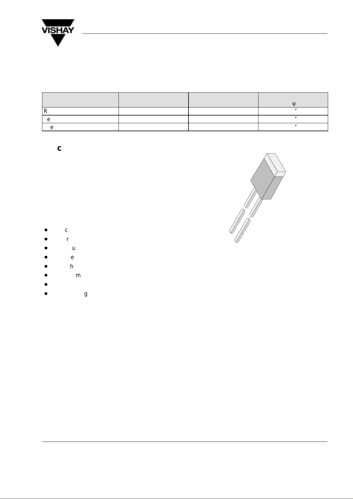
Description
This series was developed for use as compact surface
display .
It is housed in a 2x5 mm rectangular molded package.
This device has a flat tinted, top diffused package for
uniform brightness when used in panels.
The symbol LEDs are available in three bright colors:
high efficiency red, yellow and green.
±
ö
°
°
°
Features
D
Choice of three bright colors
D
Uniform illumination
D
Luminous intensity selected into groups
D
Suitable for DC and pulse operation
D
Flat light emitting surface
D
Direct symbol indication is possible
D
Yellow and green color categorized
D
Wide viewing angle
Applications
Status lights
Background illumination
Maintenance lights
Indicator of audio and visual equipment
Off / On indicator
Readout lights
Legend lights
Illumination of moving boards
96 11498
www.vishay .de • FaxBack +1-408-970-5600Document Number 83050
1 (8)Rev. A1, 04-Feb-99
TLS.210.
y
F Vmin Vmax
y
F Vmin Vmax
Vishay Telefunken
Absolute Maximum Ratings
T
= 25_C, unless otherwise specified
amb
TLSH210. ,TLSY210. ,TLSG210. ,
Parameter Test Conditions Symbol Value Unit
Reverse voltage V
DC forward current I
Surge forward current tp ≤ 10 ms I
Power dissipation T
Junction temperature T
Storage temperature range T
Soldering temperature t ≤ 5 s, 2 mm from body T
Thermal resistance junction/ambient R
Optical and Electrical Characteristics
T
= 25_C, unless otherwise specified
amb
Red (TLSH210. )
≤ 65°C P
amb
R
F
FSM
V
stg
sd
thJA
6 V
30 mA
1 A
100 mW
j
100
–55 to +100
260
°
C
°
C
°
C
350 K/W
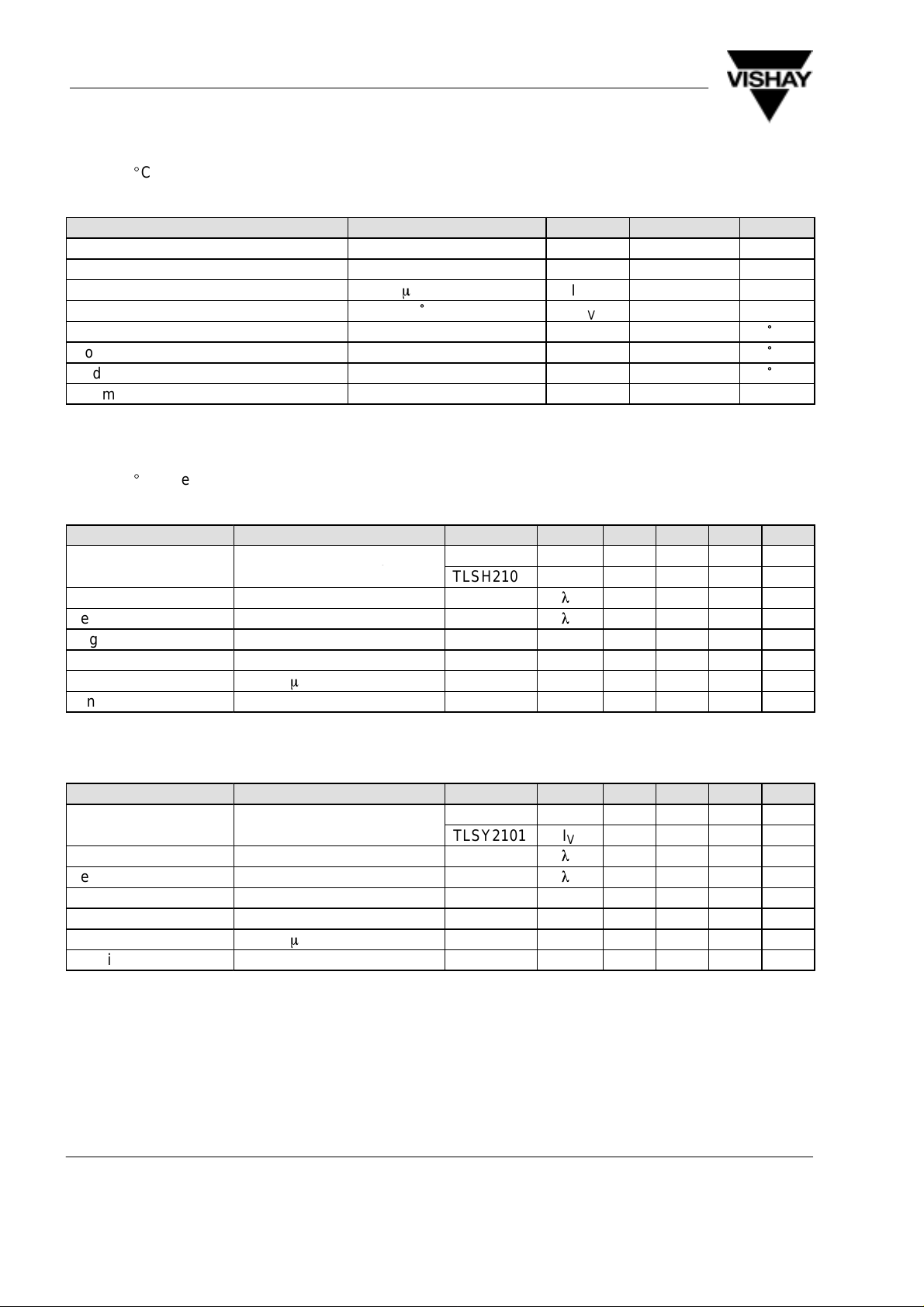
Parameter Test Conditions Type Symbol Min Typ Max Unit
Luminous intensity IF = 10 mA, I
Dominant wavelength IF = 10 mA
Peak wavelength IF = 10 mA
Vmin/IVmax
≥ 0.5 TLSH2100 I
TLSH2101 I
0.63 2 mcd
V
V
l
d
l
p
1 2.5 mcd
640 nm
650 nm
Angle of half intensity IF = 10 mA ϕ ±50 deg
Forward voltage IF = 20 mA V
Reverse voltage IR = 10 mA V
Junction capacitance VR = 0, f = 1 MHz C
F
R
j
6 15 V
2 3 V
50 pF
Yellow (TLSY210. )
Parameter Test Conditions Type Symbol Min Typ Max Unit
Luminous intensity IF = 10 mA, I
Dominant wavelength IF = 10 mA
Peak wavelength IF = 10 mA
Vmin/IVmax
≥ 0.5 TLSY2100 I
TLSY2101 I
0.63 2 mcd
V
V
l
d
l
p
1 2 mcd
581 594 nm
585 nm
Angle of half intensity IF = 10 mA ϕ ±50 deg
Forward voltage IF = 20 mA V
Reverse voltage IR = 10 mA V
Junction capacitance VR = 0, f = 1 MHz C
F
R
j
2.4 3 V
6 15 V
50 pF
www.vishay .de • FaxBack +1-408-970-5600 Document Number 83050
2 (8) Rev. A1, 04-Feb-99
TLS.210.
y
F Vmin Vmax
Vishay Telefunken
Green (TLSG210. )
Parameter Test Conditions Type Symbol Min Typ Max Unit
Luminous intensity IF = 10 mA, I
Vmin/IVmax
Dominant wavelength IF = 10 mA
Peak wavelength IF = 10 mA
Angle of half intensity IF = 10 mA ϕ ±50 deg
Forward voltage IF = 20 mA V
Reverse voltage IR = 10 mA V
Junction capacitance VR = 0, f = 1 MHz C
≥ 0.5 TLSG2100 I
TLSG2101 I
V
V
l
d
l
p
F
R
j
1 2 mcd
1.6 2.5 mcd
562 575 nm
565 nm
2.4 3 V
6 15 V
50 pF
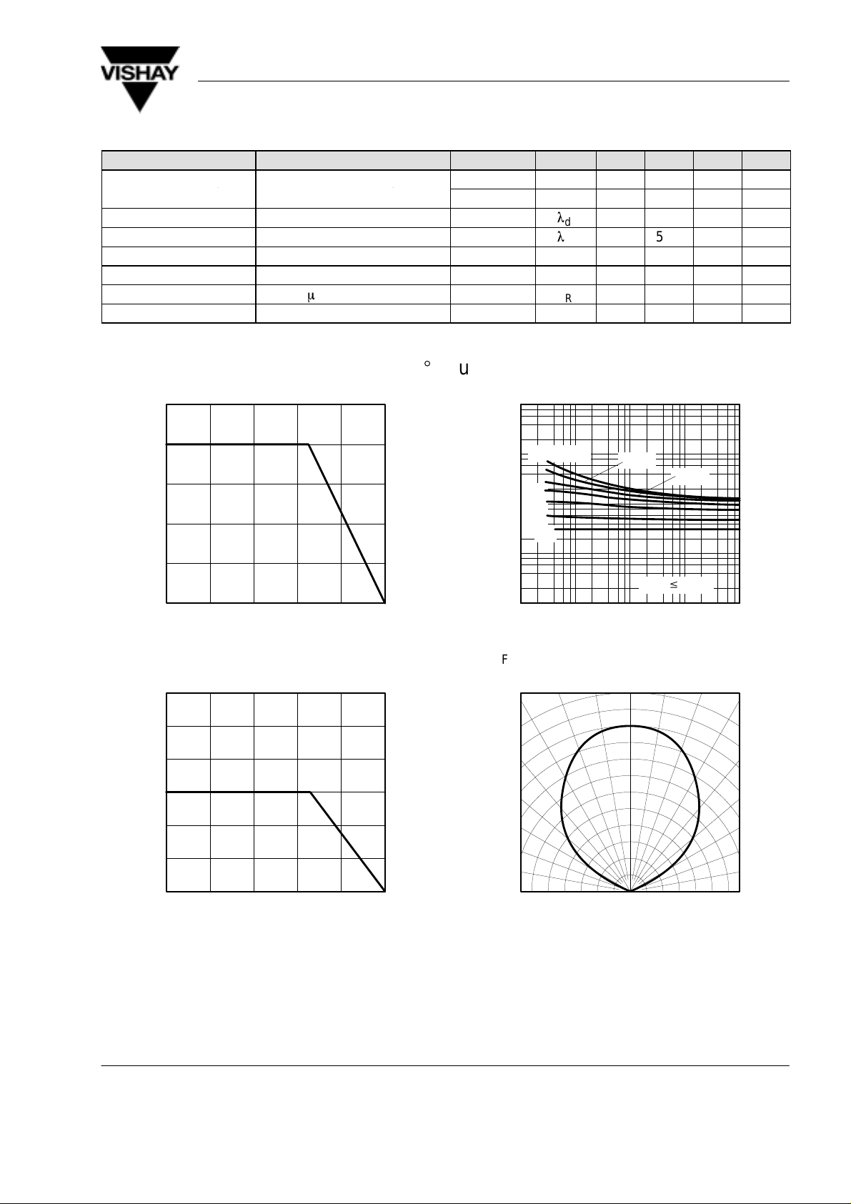
Typical Characteristics (T
125
100
75
50
V
25
P – Power Dissipation ( mW )
0
020406080
T
95 10918
– Ambient Temperature ( °C )
amb
= 25_C, unless otherwise specified)
amb
100
Figure 1 Power Dissipation vs. Ambient Temperature
60
50
40
30
10000
F
I – Forward Current ( mA )
95 10079
1000
tp/T=0.01
0.1
100
0.2
0.5
1
10
1
0.01 0.1 1 10
t
0.02
T
– Pulse Length ( ms )
p
amb
v
Figure 3 Forward Current vs. Pulse Length
0°
10°20
1.0
0.9
0.05
65°C
100
°
30°
40°
50°
F
I – Forward Current ( mA )
95 10046
Figure 2 Forward Current vs. Ambient Temperature
20
10
0
020406080
T
– Ambient Temperature ( °C )
amb
100
0.8
0.7
v rel
I – Relative Luminous Intensity
0.4 0.2 0 0.2 0.4
0.6
95 10082
60°
70°
80°
0.6
Figure 4 Rel. Luminous Intensity vs. Angular Displacement
www.vishay .de • FaxBack +1-408-970-5600Document Number 83050
3 (8)Rev. A1, 04-Feb-99
 Loading...