


TLR.440.
Vishay Telefunken
Resistor LED for 12 V Supply Voltage
Color Type Technology Angle of Half Intensity
High efficiency red TLRH4400 GaAsP on GaP 30
Soft orange TLRO4400 GaAsP on GaP 30
Yellow TLRY4400 GaAsP on GaP 30
Green TLRG4400 GaP on GaP 30
Pure green TLRP4400 GaP on GaP 30
±
ö
°
°
°
°
°
Description
These devices are developed for the automotive
industry and other industries which use 12 V sources.
The TLR.440. series contains an integrated resistor for
current limiting in series with the LED chip. This allows
the lamp to be driven from a 12 V source without an external current limiter.
Available colors are red, soft orange, yellow , green and
pure green. The luminous intensity of such an LED is
measured at constant voltage of 12 V.
These tinted diffused lamps provide a wide off-axis
viewing angle.
These LEDs are intended for space critical
applications such as automobile instrument panels,
switches and others which are driven from a 12 V
source.
Features
D
With current limiting resistor for 12 V
D
Cost effective: save space and resistor cost
D
Standard ø 3 mm (T-1) package
D
Wide viewing angle
D
Choice of five bright colors
D
Luminous intensity categorized
D
Yellow and green color categorized
D
Luminous intensity and color are measured at 12
V
94 8488
Applications
Status light in cars and other applications with a 12 V source
OFF / ON indicator in cars and other applications with a 12 V source
Background illumination for switches
Off / On indicator in switches
Document Number 83044
Rev. A1, 04-Feb-99
www.vishay .de • FaxBack +1-408-970-5600
1 (10)

TLR.440.
Vishay Telefunken
Absolute Maximum Ratings
T
= 25_C, unless otherwise specified
amb
TLRH4400 ,TLRO4400 ,TLRY4400 ,TLRG4400 ,TLRP4400
Parameter Test Conditions Symbol Value Unit
Reverse voltage V
Forward voltage T
Power dissipation T
≤ 65°C V
amb
≤ 65°C P
amb
Junction temperature T
Storage temperature range T
Soldering temperature t ≤ 5 s, 2 mm from body T
Thermal resistance junction/ambient R
R
F
V
j
stg
sd
thJA
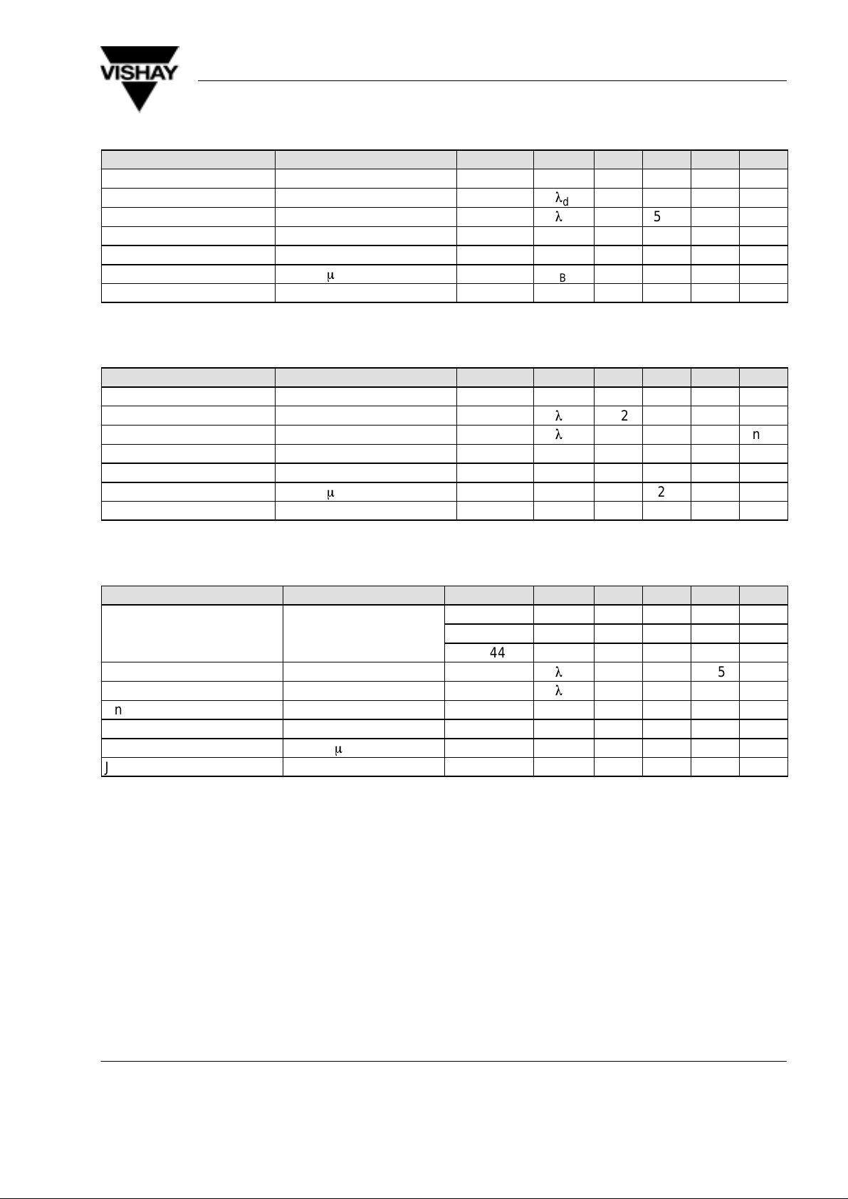
Optical and Electrical Characteristics
T
= 25_C, unless otherwise specified
amb
High efficiency red (TLRH4400 )
Parameter Test Conditions Type Symbol Min Typ Max Unit
Luminous intensity VF = 12 V I
Dominant wavelength VF = 12 V
Peak wavelength VF = 12 V
V
l
d
l
p
Angle of half intensity VF = 12 V ϕ ±30 deg
Forward current VS = 12 V I
Breakdown voltage IR = 10 mA V
F
BR
Junction capacitance VR = 0, f = 1 MHz C
1.6 4 mcd
612 625 nm
6 20 V
j
6 V
16 V
240 mW
100
–55 to +100
260
150 K/W
635 nm
10 12 mA
50 pF
°
C
°
C
°
C
Soft orange (TLRO4400 )
Parameter Test Conditions Type Symbol Min Typ Max Unit
Luminous intensity VF = 12 V I
Dominant wavelength VF = 12 V
Peak wavelength VF = 12 V
V
l
d
l
p
4 10 mcd
598 611 nm
605 nm
Angle of half intensity VF = 12 V ϕ ±30 deg
Forward current VS = 12 V I
Breakdown voltage IR = 10 mA V
Junction capacitance VR = 0, f = 1 MHz C
F
BR
6 20 V
j
10 12 mA
50 pF
www.vishay .de • FaxBack +1-408-970-5600 Document Number 83044
2 (10)
Rev. A1, 04-Feb-99
TLR.440.
y
F
Vishay Telefunken
Yellow (TLRY4400 )
Parameter Test Conditions Type Symbol Min Typ Max Unit
Luminous intensity VF = 12 V I
Dominant wavelength VF = 12 V
Peak wavelength VF = 12 V
V
l
d
l
p
Angle of half intensity VF = 12 V ϕ ±30 deg
Forward current VS = 12 V I
Breakdown voltage IR = 10 mA V
F
BR
Junction capacitance VR = 0, f = 1 MHz C
Green (TLRG4400 )
Parameter Test Conditions Type Symbol Min Typ Max Unit
Luminous intensity VF = 12 V I
Dominant wavelength VF = 12 V
Peak wavelength VF = 12 V
V
l
d
l
p
Angle of half intensity VF = 12 V ϕ ±30 deg
Forward current VS = 12 V I
Breakdown voltage IR = 10 mA V
F
BR
Junction capacitance VR = 0, f = 1 MHz C
1.6 4 mcd
581 594 nm
585 nm
10 12 mA
6 20 V
j
50 pF
1.6 4 mcd
562 575 nm
565 nm
10 12 mA
6 20 V
j
50 pF
Pure green (TLRP4400 )
Parameter Test Conditions Type Symbol Min Typ Max Unit
TLRP4400 I
Luminous intensity VF = 12 V TLRP4401 I
TLRP4406 I
Dominant wavelength VF = 12 V
Peak wavelength VF = 12 V
l
l
0.63 3 mcd
V
V
V
d
p
1.6 4 mcd
1.6 5 mcd
555 565 nm
555 nm
Angle of half intensity VF = 12 V ϕ ±30 deg
Forward current VS = 12 V I
Breakdown voltage IR = 10 mA V
Junction capacitance VR = 0, f = 1 MHz C
F
BR
6 20 V
j
10 12 mA
50 pF
Document Number 83044
Rev. A1, 04-Feb-99
www.vishay .de • FaxBack +1-408-970-5600
3 (10)
 Loading...