

Telefunken TF42K192A Service Manual
TF42K192A
.Safet y No ti ce 2 . Print ed C ir cuit Bo ar d 30
.Displ ay M od es
.Speci fi ca tions 4
.Wiring Dia gr am 36
.Locat io n an d Funct io n of
Contr ol s 6
. Ex pl oded Vi ew and Mech an ical Pa rt s 37
.Insta ll at ion and c on necti ng 8
. P ar ts L ist( Fo r Refer en ce O nly) 38
. Schem ti c Di agram s 16
2

2
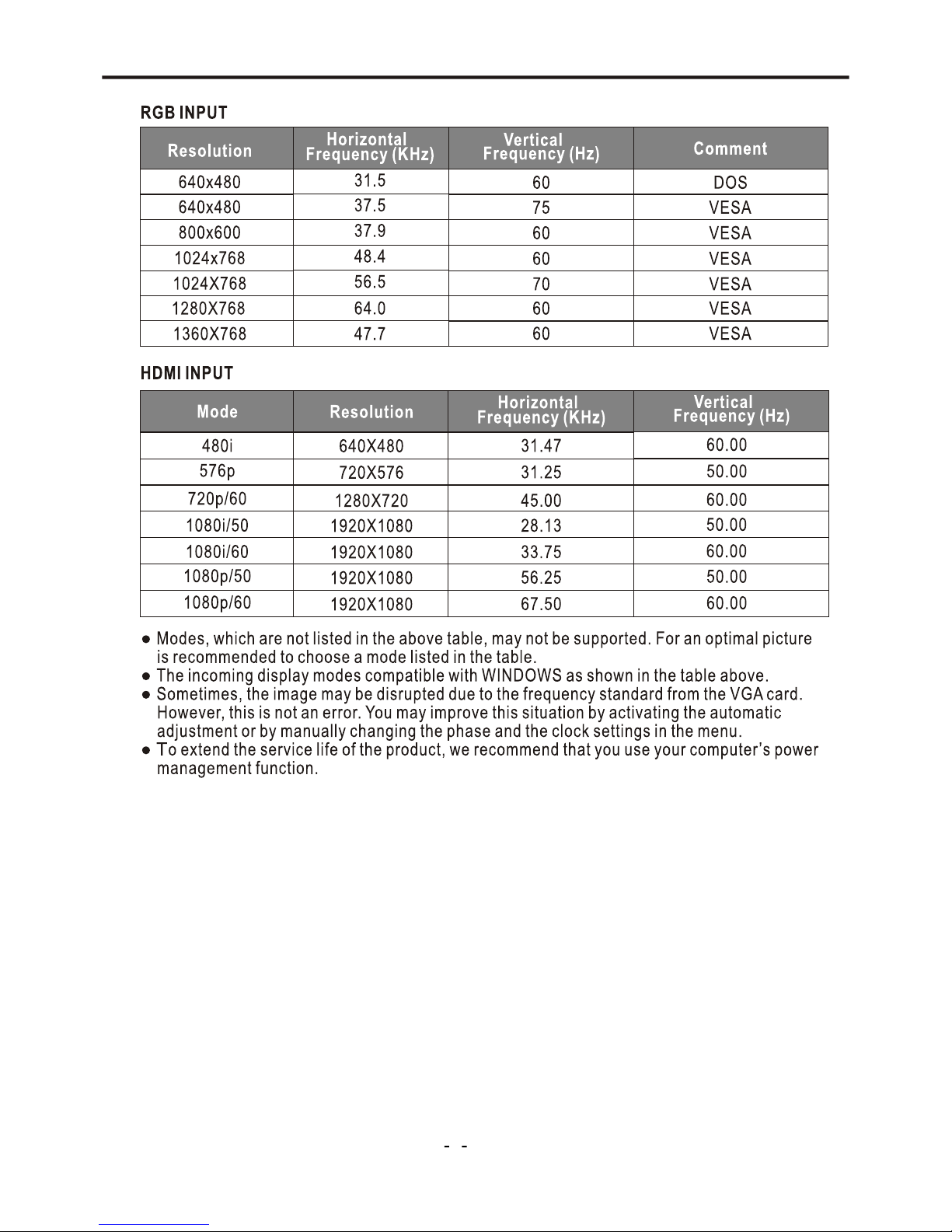
Display Modes
3

Specifications
4
LCD Panel
Size
Display size
Pixel Pitch
View Angle
Frequency
Horizontal
Vertical
Display color
Display Resolution
Maximum Mode
Optimum Mode
Input Source
Sync.
Video Signal
TV
Color System
Sound System
Video
Color System
Video Format
Power Supply
Input
RGB Signal
Power Consumption
Working
Standby
Environmental Considerations
Operating Temperature
Operating Humidity
Audio Characteristics
Dimension ( WXDXH) mm
Weight (Kg)
Net Weight
Audio Input
Frequency
Response
Audio Input (PC)
Note:
● Design and specifications are subject to change without notice.
● Weight and dimensions shown are approximate values only.
Gross Weight
Without Stand
With Stand
H/V separate, TTL, P. or N.
1Vp-p @ 75 ohm
0.7 Vp-p @ 75 ohm
PAL/SECAM
BG, DK, I, L
AC 100~240V, 50/60Hz
10℃ ~ 40 ℃(50°F ~ 104°F)
10% ~ 80%
RCA Jack (L, R), 0.5Vrms (-9dB)
RF: 100Hz~12KHz (at ± 3dB)
A/V: 100Hz~13KHz (at ± 3dB)
RCA Jack (L, R), 0.5Vrms (-9dB)
30~75KHz
56~75Hz
16.7M colors
PAL/SECAM/NTSC
CVBS, S-VHS, RGB
230W
< 3W
25
28.5
42” Diagonal
930.24(H) X 523.26 (V) mm
0.4845(H) X 0.4845 (V) mm
176 °/176°(H/V)
1360 X 768 @ 60Hz
1024 X 768 @ 60Hz
1068X122X753
1068X310X806
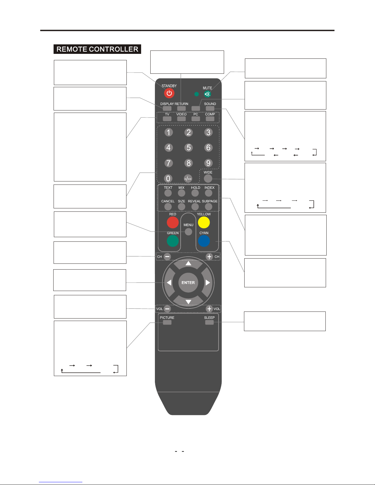
Location and Function of Controls
5
EQ MODE
You may recall the equalizer mode
by pressing this button. Each time
pressed, EQ mode is changed in
following sequence.
Off R ock Pop Live
Soft
Dance
Techno
Class ic
NICAM
Switch between NICAM Stereo,
NICAM DUAL1,NICAM DUAL2,
NICAM Mono or Mono.
INPUT SOURCE SELECT
TV button
Select the TV mode.
VIDEO button
Select a mode among AV,
S-Video and SCART.
PC button
Select the VGA and HDMI mode.
COMP button
Select the YPbPr mode.
RETURN
Return to previously selected
program number.
Note:
the prompt message “Invalid Key” will appear if you press a button for a function that is not
available.
STANDBY
Switch on the LCD TV when at
standby mode or vice versa.
MUTE
Switch the sound on or off.
DISPLAY
Display the source and channel
information.
PROGRAM SELECT
Press these buttons to select
a TV program directly.
DISPLAY MODE
You may recall the display mode
by pressing this button. Each time
pressed, display mode is changed
in following sequence.
4:3 16:9
Full
Auto
Normal
TELETEXT
These buttons are used for
certain models with Teletext
functions. For further details,
refer to “TELETEXT
FUNCTION” section.
COLOR BUTTONS
These buttons are used for program
editing function. For further details,
refer to ‘‘Program Edit ’’.
MENU SELECT
Enter or exit from the OSD
menu.
CH+/CH-
Select channel in ascending or
descending order.
p q t u and ENTER
select menu items and adjust
menu values.
VOL+/VOL-
Press to increase or decrease
volume.
SLEEP
To select the sleep time.
PICTURE MODE
You may recall the picture
mode by pressing this button.
Each time pressed, picture
mode is changed in following
sequence:
Sport Vivid Hi-Bright
User
NICAM

Location and Function of Controls
6
6
7
5
4
3
2
_
+
INPUT
1
Note:
If there is no signal input from VGA/HDMI mode for 5 minutes or other video modes for 15 minutes,
it will switch to standby mode automatically.
Main Power Switch Switch on/off the LCD TV
INPUT
8
FRO N T PANEL

Installation and Connecting
7
3
4
5
7
9
10
11
HDMI 2 IN
2
HDMI 1 IN
SCAR T1
SCAR T2
1
AC IN
S-VI DEO
VIDE O
R L
75
Y
Pb
Pr
R L
6
8
VGA IN
(D-S UB 15PI N)
LINE I N
1
AC Input Socket: Connect to an earth 100-240V, 50/60Hz AC outlet with the power cable.
2
HDMI1/2 Input Connectors: Connect it to the HDMI of DVD or other equipment.
3
VGA Input Terminal: For PC display. Connect it to the D-Sub 15 pins analog output connector
of the PC.
4
S-VIDEO Terminal: Connect it to S-Video output terminal of DVD.
5
LINE IN (VGA Audio) Terminal: Connect it to the audio output terminal of PC.
YPbPr Component Video Input Terminals: Connect them to the video output terminal of DVD.
6
7
VIDEO IN Terminal: Connect it to video output terminal of DVD.
8
YPbPr Audio In Terminals: Connect them to the audio output terminal of DVD with YPbPr mode.
9
AV Audio In Terminals: Connect them to the audio output terminal of DVD with VIDEO/S-VIDEO
mode.
SCART1/2 Connectors: Connect them to the composite terminal of DVD.
10
RF Input Socket: Connect antenna or cable 75 Ohm coaxial to receive TV signal.
11
Ω
8
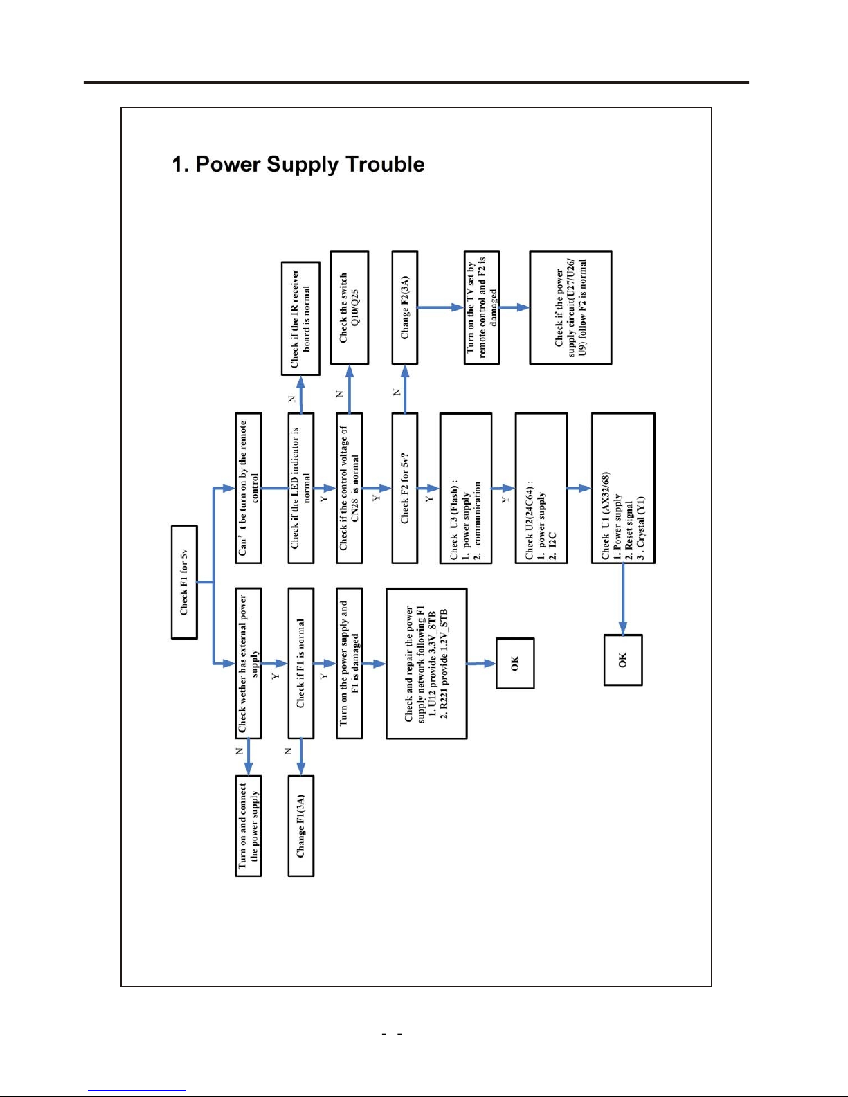
Trouble shooting charts
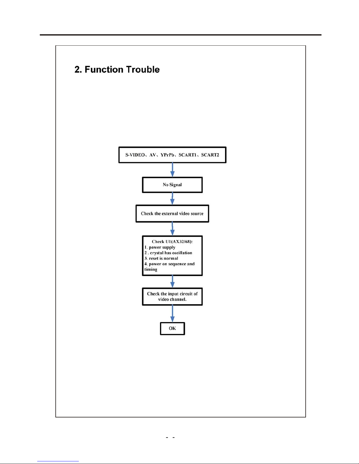
9
Trouble shooting charts
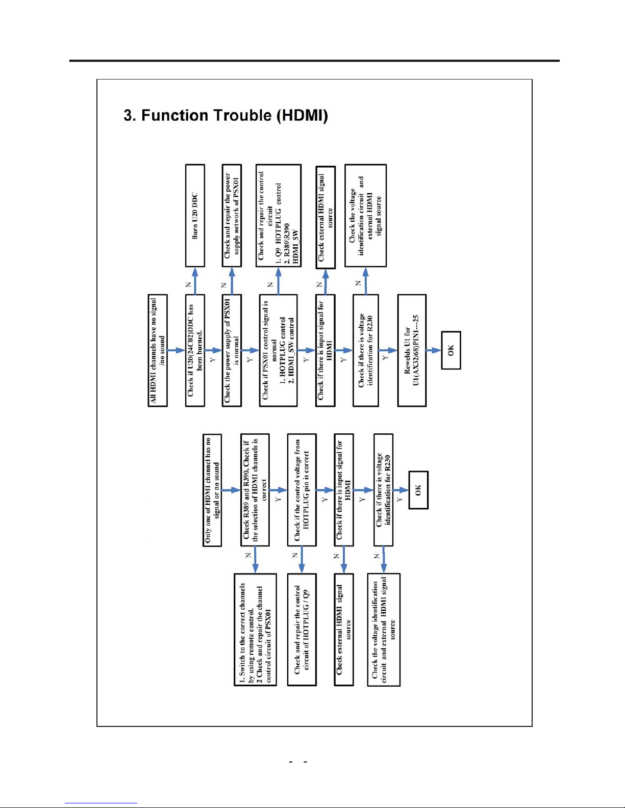
Trouble shooting charts
10
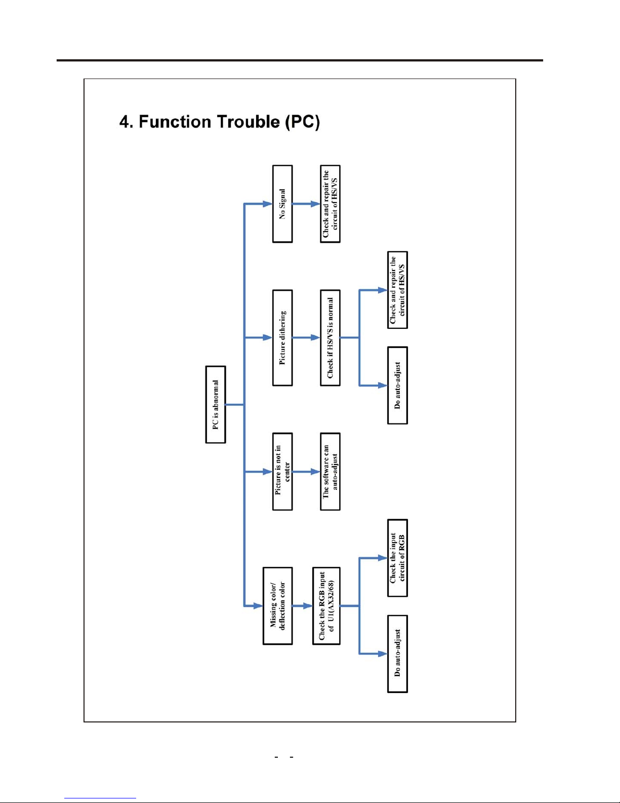
Trouble shooting charts
11

Trouble shooting charts
12
 Loading...