

Page 1
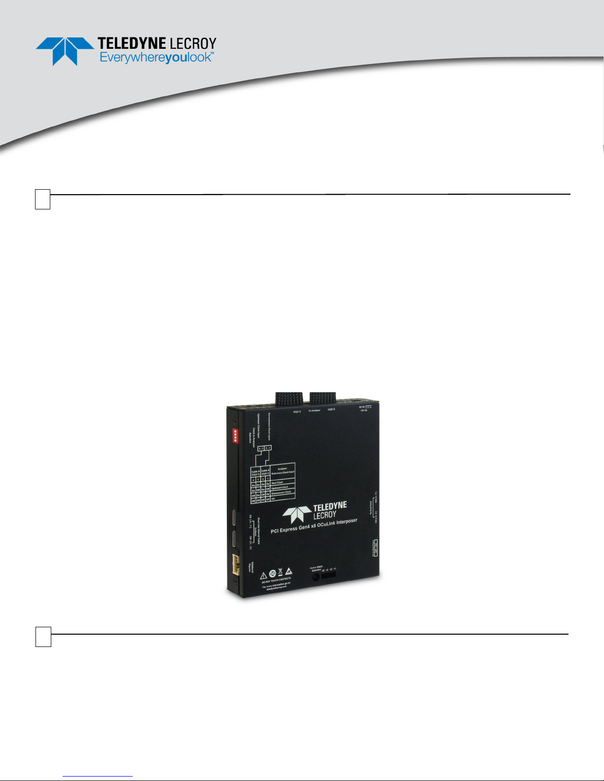
PCI Express® Gen4 x8 OCuLink Interposer
User Manual and Quick Start Guide
Before Starting
Use this document for quick installation and setup. If you experience problems or
need more information, see the product manuals available at the Teledyne LeCroy
web site or in the Documents folder in the PCIe Protocol Suite installation DVD.
1
Introduction
Teledyne LeCroy's PCI Express Gen4 x8 OCuLink Cable Interposer for the Summit™ PCI Express Protocol Analyzer product line provides
individual dedicated probes, making it easy to capture and analyze data traffic between a host and device that are connected using a
PCIe® OCuLink type cable based on the PCI Express OCuLink Cable specification. The PCI Express Gen4 x8 OCuLink Interposer taps
into the OCuLink point to point connection to allow an analyzer to capture and decode data traffic between two systems. It supports data
rates of 2.5 GT/s, 5.0 GT/s, 8.0 GT/s and 16.0 GT/s. The interposer assures reliable data transmission while providing 100% capture of
all data traffic flowing through the PCIe interface. Connecting the interposer to a Teledyne LeCroy analyzer allows analyzer to decode and
display data in both directions and across all lanes.
One PCIe OCuLink Cable can support PCIe link widths from x1 to x4. Larger links can be achieved by adding additional cables, e.g. a x8
link uses two PCIe OCuLink cables. The PCI Express OCuLink Specification allows in addition to in-band PCIe signaling the passage of
sideband signals such as PERST#, WAKE#, CLKREQ# and SMBus by passing them electrically through the link. The sideband signaling
(PERST#, WAKE#, CLKREQ#, SMBus and other functionality) can be monitored by the protocol analyzer through the interposer, where
protocol issues and performance metrics can be analyzed and debugged. RefClk signals external to the cable are also available on the
PCIe OCuLink Cable Interposer for use with the protocol analyzer.
The PCI Express Gen3 x8 OCuLink Interposer works with the PCIe OCuLink cable (or set of cables) up to 0.6 meter in length as defined
in the PCI Express OCuLink Cable specification.
PCI Express Gen4 x8 OCuLink Interposer
2
Components
The interposer package includes the following components:
• PCI Express Gen4 x8 OCulink Interposer
• PCIe OCuLink Internal Cables (Two PE017UCA-X cables 60cm each)
• DC Power Adapter (12 volts @ 5A)
• User Manual and Quick Start Guide (this document)
Inspect the received shipping container for any damage. Unpack the container and account for each of the system components listed on
the accompanying packing list. Visually inspect each component for absence of damage.
In the event of damage, notify the shipper and Teledyne LeCroy. Retain all shipping materials for shipper’s inspection.
Page 2

3
PCI Express Gen4 x8 OCuLink Interposer Interconnection Overview
12V DC from
adapter
supplied
Summit PCIe Gen 4
capable Analyzer
Switches Settings
for Clock inputs
(see Table 1 on
page iii below)
AB
OCuLink Device side
(use internal or external cables)
OCuLink Root side
(use internal cables)
+5V to
Device
(End-Point)
(see Ta bl e 3
on page iii)
Active
Width
Selection
Switch
(see
Table 2 on
page iii)
iPass Cable: Interposer to Analyzer
T416: PE016UCA-X
J11: Sideband
Signals Test Points
(see Table 4 on
page iv and Ta bl e 5
on page iv)
Upstream
Downstream
Calibration
connector
Connections
Perform to the following steps to connect the Interposer (see the image below):
1. Connect the supplied Teledyne LeCroy PCIe OCuLink Internal cable (PE017UCA-X) between the CH[0:3] port on the Root side of the interposer and
Port-0 of the OCuLink root. If x8 configuration is required, connect both Teledyne LeCroy PCIe OCuLink internal cables between the Root side ports
of the interposer and Port-0 and Port-1 of the OCuLink root.
2. If working in x4 configuration with an internal device, connect the second Teledyne LeCroy PCIe OCuLink Internal cable (PE017UCA-X) between the
CH[0:3] port on the Device side of the interposer and Port-0 of the OCuLink device. If x8 configuration is required use two off-the-shelf cables to connect the End Point side ports from the interposer to Port-0 and Port-1 of the OCuLink device. If working with external devices you will need an off the
shelf 0.6m external cable.
3. Connect the Summit PCIe Gen 4 capable analyzer to the interposer as indicated in the diagram below.
4. Install the PCIe Protocol Analysis Software on the host machine. This application is needed to control the protocol analyzer.
5. Connect the analyzer to a host machine (where the PCIe Protocol Analysis Software application will be running) using the USB or Ethernet port on
the back panel of the Summit analyzer (or other compatible Teledyne LeCroy analyzer.
6. Connect 12V DC using the AC adapter supplied with the interposer. Make sure that the AC adapter is turned on.
7. Power on the analyzer.
8. Power on the host/root complex system.
9. Use the Teledyne LeCroy software application to monitor, record and view PCI Express traffic in the PCIe expansion card DUT system. Use Internal
Clock in the recording options tab of the application. In order to improve lock time for analyzer provide reference clocks for upstream and downstream and use External Clock option.
Note: Steps 6, 7, and 8 are needed in this order for power on traces.
Page 3

Cable A
US[0:7]
Cable B
DS[0:7]
Analyzer
Reference
Clock Input
SW1-4 SW1-3 SW1-2 SW1-1
ON ON ON ON Host Clock
ON OFF ON OFF Upstream Clock
OFF ON OFF ON Downstream Clock
OFF OFF OFF OFF NA
Note 1: Factory settings for all switches are ON.
Note 2: Host Clock is sourced from the Root System OCuLink
connector VSP pins A12/A13.
Note: Factory settings for the switch is x8.
The Active Width Selection switch allows user to select the maximum link
width to be used for traffic capture. Keep toggling the switch to cycle through
all possible link widths: x1, x2, x4 and x8. An LED will indicate the current
selection.
SW3 Active Link Width Selection Switch
x8 Link Width Set to 8
x4 Link Width Set to 4
x2 Link Width Set to 2
x1 Link Width Set to 1
SW4
+5V Selector Switch
to Device (End-Point)
OFF No +5V to Device (End-Point)
ON +5V to Device (End-Point)
Note: Factory setting for the switch is OFF.
5V to End Point
OFF - ON
4
Switch Settings: Clocks, Link Width, Power to Device
Table 1: Switch Settings for Clock Inputs and Cable Configurations: SW1
Table 2: Switch Settings for Active Link Width Selection: SW3
Table 3: Switch Settings for +5V to Device (End-Point): SW4
Page 4

5
Test Points
Table 4: J11 Sideband Signal Test Points
PIN DESCRIPTION PIN DESCRIPTION
1 CH[0:3] Port BP TYPE 6 CH[4:7] Port PERST#
2 CH[4:7] Port BP TYPE 7 CH[0:3] Port CPRSNT#
3 CH[0:3] Port CWAKE# 8 CH[4:7] Port CPRSNT#
4 CH[4:7] Port CWAKE# 9 GND
5 CH[0:3] Port PERST# 10 GND
Table 5: J11 Sideband Signal Descriptions
SIGNAL NAME DESCRIPTION
BP TYPE Input required to enable a full crossover internal cable solution.
WAKE# Power management signal for Downstream device wakeup events.
PERST# PCI Express Reset indicates when the applied main power is within the specified tolerance and is stable.
CPRESNT# Cable present signal
6
Environmental Conditions
• Temperature: Operating 32° F to 122° F (0° C to 50° C)
• Temperature: Non-Operating 14° F to 176° F (-10° C to 80° C)
• Humidity: Operating 10% to 90% RH (non-condensing)
Teledyne LeCroy Customer Support
Online Download
Periodically check the Teledyne LeCroy Protocol Solutions Group
web site for software updates and other support related to this
product. Software updates are available to users with a current
Maintenance Agreement.
Trademarks and Servicemarks
Teledyne LeCroy, PCIe Protocol Suite, PCIe Protocol Analysis,
Summit T416 are trademarks of Teledyne LeCroy. All other
trademarks are property of their respective companies.
Web: teledynelecroy.com/tm/software/PCIe
E-mail: psgsupport@teledyne.com
Support: teledynelecroy.com/support/contact
Changes
Product specifications are subject to change without notice.
Teledyne LeCroy reserves the right to revise the information in this
document without notice or penalty.
© 2017 Teledyne LeCroy, Inc. All rights reserved. Part Number: 928747-00 Rev A
This document may be printed and reproduced without additional permission, but all copies should contain this copyright notice.
 Loading...