


Operator’s
Manual
ArbStudio
Arbitrary Waveform
Generator

ArbStudio
Arbitrary Waveform Generator
Operator’s Manual
January 2013

© 2013 Teledyne LeCroy, Inc. All rights reserved.
Unauthorized duplication of Teledyne LeCroy documentation materials other than for internal sales and distribution purposes is strictly prohibited. However, clients are encouraged to distribute and duplicate Teledyne LeCroy documentation for their own internal educational purposes.
ArbStudio and Teledyne LeCroy are registered trademarks of Teledyne LeCroy. Windows is a registered trademark of Microsoft Corporation. Other product or brand names are trademarks or requested trademarks of their respective holders. Information in this publication supersedes all earlier versions. Specifications are subject to change without notice.
Warranty
NOTE: THE WARRANTY BELOW REPLACES ALL OTHER WARRANTIES, EXPRESSED OR IMPLIED, INCLUDING BUT NOT LIMITED TO ANY IMPLIED WARRANTY OF MERCHANTABILITY, FITNESS, OR ADEQUACY FOR ANY PARTICULAR PURPOSE OR USE. TELEDYNE LECROY SHALL NOT BE LIABLE FOR ANY SPECIAL, INCIDENTAL, OR CONSEQUENTIAL DAMAGES, WHETHER IN CONTRACT OR OTHERWISE. THE CUSTOMER IS RESPONSIBLE FOR THE TRANSPORTATION AND INSURANCE CHARGES FOR THE RETURN OF PRODUCTS TO THE SERVICE FACILITY. TELEDYNE LECROY WILL RETURN ALL PRODUCTS UNDER WARRANTY WITH TRANSPORT PREPAID.
The ArbStudio is warranted for normal use and operation, within specifications, for a period of three years from shipment. Teledyne LeCroy will either repair or, at our option, replace any product returned to one of our authorized service centers within this period. However, in order to do this we must first examine the product and find that it is defective due to workmanship or materials and not due to misuse, neglect, accident, or abnormal conditions or operation.
Teledyne LeCroy shall not be responsible for any defect, damage, or failure caused by any of the following: a) attempted repairs or installations by personnel other than Teledyne LeCroy representatives or b) improper connection to incompatible equipment, or c) for any damage or malfunction caused by the use of non-Teledyne LeCroy supplies. Furthermore, Teledyne LeCroy shall not be obligated to service a product that has been modified or integrated where the modification or integration increases the task duration or difficulty of servicing the instrument. Spare and replacement parts, and repairs, all have a 90-day warranty.
The instrument's firmware has been thoroughly tested and is presumed to be functional. Nevertheless, it is supplied without warranty of any kind covering detailed performance. Products not made by Teledyne LeCroy are covered solely by the warranty of the original equipment manufacturer.
922244-00 Rev A
January 2013

Operator’s Manual |
|
TABLE OF CONTENTS |
|
Welcome .................................................................................................... |
1 |
Minimum System Requirements ................................................................. |
1 |
Suggested System Requirements ................................................................ |
2 |
Package Contents ........................................................................................ |
2 |
Safety Instructions ...................................................................................... |
3 |
Symbols........................................................................................................ |
3 |
Precautions .................................................................................................. |
3 |
Operating Environment ............................................................................... |
4 |
Cooling ......................................................................................................... |
5 |
Cleaning ....................................................................................................... |
5 |
Calibration.................................................................................................... |
5 |
Power........................................................................................................... |
6 |
Front Panel................................................................................................... |
7 |
Back Panel.................................................................................................... |
8 |
Getting Started with ArbStudio ................................................................. |
10 |
Overview.................................................................................................... |
10 |
Software and Driver Installation................................................................ |
10 |
Initial ArbStudio Software Interfaces ........................................................ |
17 |
Setup Examples and Common Tasks ......................................................... |
23 |
Channel Settings ....................................................................................... |
32 |
Overview.................................................................................................... |
32 |
Channel Settings - The General Tab........................................................... |
33 |
Channel Settings - The Run Mode Tab (Waveform Sequence) ................. |
35 |
Channel Settings - Run Mode Tab (Modulation) ....................................... |
39 |
Channel Settings - The Trigger IN Tab........................................................ |
40 |
Channel Settings - Trigger OUT Tab........................................................... |
42 |
Setup System............................................................................................ |
43 |
Setup Device............................................................................................. |
45 |
Timing Tab ................................................................................................. |
45 |
922244-00 Rev A |
i |
|

ArbStudio |
|
Channel Out Math Tab.............................................................................. |
47 |
Trigger OUT Math Tab............................................................................... |
48 |
Digital I/O Tab ........................................................................................... |
49 |
Strobe Tab................................................................................................. |
50 |
The Waveform Sequencer - Analog ........................................................... |
51 |
Creating Standard and Advanced Waveforms.......................................... |
51 |
Waveform Graph Toolset.......................................................................... |
59 |
Advanced Waveform Editing .................................................................... |
61 |
Segment Editing ........................................................................................ |
63 |
Component Type....................................................................................... |
66 |
Segment Parameters................................................................................. |
67 |
Waveform Parameters.............................................................................. |
67 |
Markers..................................................................................................... |
71 |
Sequencing Analog Waveforms ................................................................ |
73 |
Additional Waveform Sequencer Settings/Tools...................................... |
75 |
Modulation Editor - Arbitrary/DDS............................................................ |
83 |
Overview ................................................................................................... |
83 |
Hardware Resources................................................................................. |
83 |
Edit Modulation Rule ................................................................................ |
84 |
Modulation Type....................................................................................... |
84 |
Modulating Table...................................................................................... |
85 |
Command Bar ........................................................................................... |
85 |
Modulation Entry Editor ........................................................................... |
86 |
Modulation Segment Editor...................................................................... |
87 |
Amplitude Profile Editor (DDS) .................................................................. |
89 |
Limits Settings ........................................................................................... |
90 |
Profile Command ...................................................................................... |
90 |
Digital Pattern Generator - Sampler (Optional) .......................................... |
91 |
Pattern (Sampling and Acquisition) Settings ............................................ |
92 |
Example - Digital Pattern Generator Setup ............................................ |
103 |
ii |
922244-00 Rev A |
|

Operator’s Manual |
|
Waveform Sequencer - Digital Pattern.................................................... |
110 |
Signal Definitions ..................................................................................... |
125 |
Acquisition - Using The Pattern Generator as a Sampler ........................ |
127 |
Probes ...................................................................................................... |
137 |
The Pulse Width Modulation (PWM) Generator Workspace ..................... |
140 |
Pulse Definition Area ............................................................................... |
141 |
Duty Cycle Modulation Area.................................................................... |
142 |
Control Area............................................................................................. |
143 |
Example - PWM Setup ............................................................................. |
145 |
"How do I" Scenario Details .................................................................... |
146 |
Creating Your First Analog Waveform ..................................................... |
147 |
Creating a Sequence of Waveforms ........................................................ |
151 |
Creating an Amplitude Modulated Waveform ........................................ |
155 |
Creating a Frequency Modulated Waveform .......................................... |
161 |
Creating a Phase Modulated Waveform ................................................. |
166 |
Importing a Waveform from an Oscilloscope.......................................... |
171 |
Creating Digital Waveforms..................................................................... |
175 |
Creating Waveforms Using Formulas ....................................................... |
181 |
Overview.................................................................................................. |
181 |
Steps to Creating Advanced Waveform Components Using Formulas ... |
182 |
Exponentially Decaying Sine Wave.......................................................... |
187 |
Ramp........................................................................................................ |
188 |
Rising Exponential.................................................................................... |
189 |
Decaying Exponential .............................................................................. |
190 |
Sine .......................................................................................................... |
191 |
Linear Amplitude Sweep of a Sine Wave................................................. |
192 |
Frequency Modulation ............................................................................ |
193 |
Phase Modulation.................................................................................... |
194 |
Linear Frequency Sweep.......................................................................... |
195 |
Gaussian Pulse ......................................................................................... |
196 |
922244-00 Rev A |
iii |
|

ArbStudio |
|
Lorentzian Pulse...................................................................................... |
197 |
Amplitude Modulated Sine..................................................................... |
198 |
Full-Wave Rectified Sine ......................................................................... |
199 |
Half-Wave Rectified Sine......................................................................... |
200 |
Reference............................................................................................... |
201 |
Certifications........................................................................................... |
201 |
Windows® License Agreement ................................................................ |
203 |
End-User License Agreement for Teledyne LeCroy® X-Stream Software 203 |
|
Contact Teledyne LeCroy ........................................................................ |
215 |
Index...................................................................................................... |
216 |
iv |
922244-00 Rev A |
|

Operator’s Manual
Welcome
Thank you for purchasing a Teledyne LeCroy ArbStudio.
ArbStudio is a series of high performance Arbitrary Waveform Generators (AWG) consisting of 2 and 4 channel models, 2 Mpts/ch memory, 16 bit resolution and a maximum sample rate of 1 GS/s. Some models provide the ability to generate 18 or 36 channel digital patterns and all models can be operated in true arbitrary mode or Direct Digital Synthesis (DDS) mode.
We truly hope these materials provide increased comprehension when using Teledyne LeCroy's fine products.
Sincerely,
David C. Graef
Teledyne LeCroy Corporation
Vice President and Chief Technology Officer
Minimum System Requirements
Operative system Microsoft™ Windows® 2000, Windows® XP,
Windows® Vista 32 Bit Version, Windows® 7 32 Bit Version.
Pentium® III processor.
512 MBytes RAM.
150 MBytes hard disk available space for software set-up.
Video resolution 800 X 600.
USB 2.0 or 1.1 connections.
922244-00 Rev A |
1 |

ArbStudio
Suggested System Requirements
Operative system Microsoft™ Windows® XP, Windows® Vista 32 Bit
Version, Windows® 7 32 Bit Version.
Pentium® IV processor.
1.5 GBytes RAM.
Video resolution 1024 X 768.
USB 2.0 connection.
Package Contents
The standard ArbStudio 1102/1104 package includes the following:
ArbStudio 1102/1104 Arbitrary Waveform Generator
Standard USB 2.0 Cable
Power Supply Adapter
Power Cord
Installation CD containing the ArbStudio Software setup files,
ArbStudio Function Generator software, Drivers, and the Getting Started Manual.
Performance/Calibration Certificate
ArbStudio Introduction and Compliance document
-D Models include a ‘Digital Leadset’
2 |
922244-00 Rev A |
Operator’s Manual
Safety Instructions
This section contains instructions that must be observed to keep the instrument operating in a correct and safe condition. You are required to follow generally accepted safety procedures in addition to the precautions specified in this section. The overall safety of any system incorporating this instrument is the responsibility of the assembler of the system.
Symbols
These symbols appear on the instrument's front or rear panels and in its documentation to alert you to important safety considerations.
CAUTION of damage to instrument, or WARNING of hazard to health. Attend to the accompanying information to protect against personal injury or damage. Do not proceed until conditions are fully understood and met.
WARNING. Risk of electro-shock.
Measurement ground connection.
Safety (protective) ground connection.
Alternating Current.
Precautions
Use proper power cord. Use only the power cord shipped with this instrument and certified for the country of use.
Maintain ground. This product is grounded through the power cord grounding conductor. To avoid electric shock, connect the external AC adapter only to a grounded mating outlet.
Connect and disconnect properly. Do not connect/disconnect probes or test leads while they are connected to a voltage source.
922244-00 Rev A |
3 |

ArbStudio
Observe all terminal ratings. Do not apply a voltage to any input that exceeds the maximum rating of that input. Refer to the front of the instrument for maximum input ratings.
Use only within operational environment listed. Do not use in wet or explosive atmospheres.
Use indoors only.
Keep product surfaces clean and dry.
Do not block the cooling vents. Leave a minimum six-inch (15 cm) gap between the instrument and the nearest object. Keep the underside clear of papers and other objects.
Do not remove the covers or inside parts. Refer all maintenance to qualified service personnel.
Do not operate with suspected failures. Do not use the product if any part is damaged. Obviously incorrect measurement behaviors (such as failure to calibrate) might indicate impairment due to hazardous live electrical quantities. Cease operation immediately and sequester the instrument from inadvertent use.
Operating Environment
The instrument is intended for indoor use and should be operated in a clean, dry environment. Before using this product, ensure that its operating environment is maintained within these parameters:
Temperature: 0 °C to 50 °C
NOTE: Power Supply Adapter for ArbStudio 1104 is rated for 40 °C max.
Humidity: Maximum relative humidity 80% (non-condensing) for temperatures up to 40 °C decreasing linearly to 50 % relative humidity at 50 °C.
Altitude: Up to 10,000 ft (3,048 m) at or below 30 °C.
4 |
922244-00 Rev A |

Operator’s Manual
Cooling
The instrument relies on forced air cooling with internal fans and vents. Take care to avoid restricting the airflow to any part of the instrument. Around the sides and rear, leave a minimum of 15 cm (6 inches) between the instrument and the nearest object. At the bottom, the instrument feet (up or down) provide adequate clearance.
CAUTION. Do not block instrument vents. Always keep the area beneath the instrument clear of paper and other items.
The instrument also has internal fan control circuitry that regulates the fan speed based on the ambient temperature. This is performed automatically after start-up.
Cleaning
Clean only the exterior of the instrument using a damp, soft cloth. Do not use harsh chemicals or abrasive elements. Under no circumstances submerge the instrument or allow moisture to penetrate it. Avoid electric shock by unplugging the power cord from the AC outlet before cleaning.
CAUTION. Do not attempt to clean internal parts. Refer to qualified service personnel.
Calibration
The recommended calibration interval is one year. Calibration should be performed by qualified personnel only.
CAUTION. It is required that all inputs be removed from the instrument prior to performing a manual calibration.
Schedule an annual factory calibration as part of your regular maintenance. Extended warranty, calibration, and upgrade plans are available for purchase. Contact your Teledyne LeCroy sales representative or customersupport@teledynelecroy.com to purchase a service plan.
922244-00 Rev A |
5 |

ArbStudio
Power
Power Consumption
35 VA (35 W) Max
AC Power Source
For External AC Adapter:
100 to 240 VAC (+/-10%) at 45-66 Hz
No manual voltage selection is required because the external AC Adapter automatically adapts to line voltage.
Standby Power
The  Power (Standby) button controls the operational state of the instrument. Press the button to switch the instrument On or into Standby mode (Off).
Always use the Power button to execute a proper shut down process and preserve settings before powering down.
6 |
922244-00 Rev A |
Operator’s Manual
Hardware Inputs and Outputs
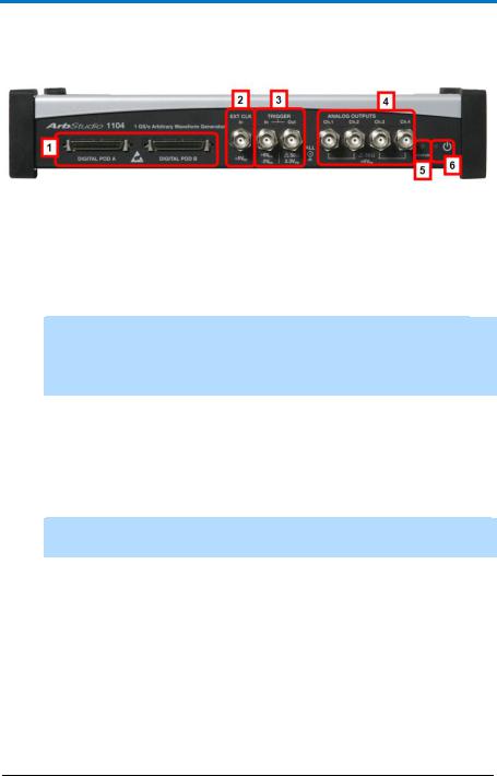
Front Panel
Figure 3-1. ArbStudio 1104 model with a POD B connector and two additional Channel Outputs. Although digital pods appear on all models, they are only active on 1102D and 1104D models.
DIGITAL POD A / DIGITAL POD B
1.DIGITAL POD A / DIGITAL POD B Probe connectors
NOTE: DIGITAL POD B is only available on ArbStudio 1104. POD A and POD B are only active on 1102D and 1104D models. ArbStudio 1102 and 1104 can be upgraded to include the digital pattern generator.
2.EXT CLK BNC input connector for external clock
3.TRIGGER
Trigger Out - BNC output connector for Trigger OUT.
Trigger In - BNC input connector for Trigger IN.
4.ANALOG OUTPUTS 12 V to 12 V BNC output connector
NOTE: Ch3 and Ch4 are only available on ArbStudio 1104 and 1104D
models.
5.STATUS LED Indicates instrument power status
6.POWER-ON LED Indicates the power status of the instrument. The status led can be OFF, ON, or Blinking denoting the following conditions:
OFF. The instrument is ON and connected to a PC, but drivers have not been installed.
ON. The instrument is ON, connected to a PC, and correctly configured.
Blinking. ArbStudio 1102/1104 is uploading firmware for channels.
922244-00 Rev A |
7 |
ArbStudio
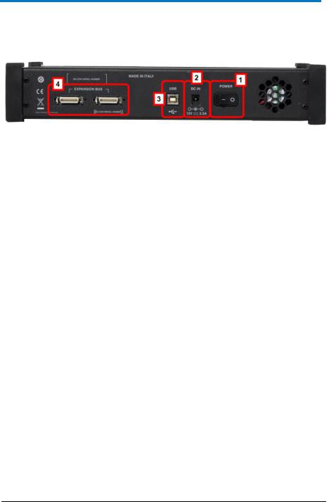
Back Panel
Numbered callouts on this image correspond with the following descriptions.
1.POWER - The power switch.
2.DC IN - 12 V – 2.5 A DC connector.
3.USB - USB 2.0 connector.
4.EXPANSION BUS - The Expansion bus connector is located on the rear panel of the ArbStudio 1104 and 1104D models only. Using the appropriate expansion cable, up to 8 total 4 Channel ArbStudio units may be connected.
It is possible to have a system with up to 8 independent arbitrary waveform generators, each with the ability to have a synchronized trigger.
PLEASE NOTE THE FOLLOWING:
ArbStudio 1104 and 1104D units sharing the Expansion bus must all be connected to the same controller (PC) via USB or hub.
If more than one ArbStudio 1104 or 1104D are connected to the same PC, they must also be linked through the Expansion bus.
Making Expansion Bus Connections
In order to connect several ArbStudio 1104 or 1104D units you must first:
Connect the ArbStudio units using the Expansion bus.
Connect all ArbStudio units to a single PC by using an USB connector or by using a HUB.
Ensure all ArbStudio units are correctly recognized by the operating system.
8 |
922244-00 Rev A |

Operator’s Manual
When you launch the ArbStudio software, if all the correct connections are made, the instruments are shown as connected together. The interconnected instruments make up your complete ArbStudio system.
Removing Expansion Bus Connections
Before disconnecting or switching off the instrument, it must be removed by left clicking the Safely Remove Hardware icon showing in the Windows System Tray on your PC.
When your operating system eventually shows a Safely Remove Hardware screen, select Safely remove Teledyne LeCroy ArbStudio, and then click the Stop button.
NOTE: If the instrument is switched off or disconnected without performing the proper safe removal process, the software may not operate correctly.
922244-00 Rev A |
9 |

ArbStudio
Getting Started with ArbStudio
Overview
This Getting Started section begins by providing essential installation instructions for Drivers and Software. Then, the initial software interfaces are introduced. Finally, Setup Examples and Common Tasks are provided to bring you up to speed as fast as possible.
The How do I section of the ArbStudio Welcome screen contains links to step-by-step explanations of standard functions and setups using your new product.
These titles along with others provided here and in other locations of this documentation provide accurate descriptions for regular tasks.
Software and Driver Installation
Insert the installation CD into your CD/DVD reader on your computer.
If the Welcome screen is not automatically shown, run the cdstart.exe file on the root directory of the installation files.
10 |
922244-00 Rev A |

Operator’s Manual
The one installer guides you through proper setup of both the ArbStudio software and necessary drivers for your computer as explained in the following topics.
Software Installation
NOTE: The Microsoft .NET Framework 2.0 Run-Time Engine (or greater) is required to run the ArbStudio 1102/1104 software properly.
After inserting the installation CD into your CD/DVD reader, the Welcome screen is eventually shown, click Install Teledyne LeCroy ArbStudio to start setting up the software.
The ArbStudio Setup Wizard is then shown. Click Next to proceed with the installation.
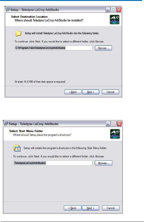
You can leave the default Installation Folder path, or specify a new location and click Next.
922244-00 Rev A |
11 |
ArbStudio
Now, either leave the default Start Menu folder path, or specify a new location and click Next.
12 |
922244-00 Rev A |
Operator’s Manual
Use the next screen in the wizard to have the installation configure Desktop shortcuts/icons for ArbStudio, ArbStudio Function Generator, and
ArbStudio PWM Generator. Mark the checkboxes for the desired tasks and and click Next.
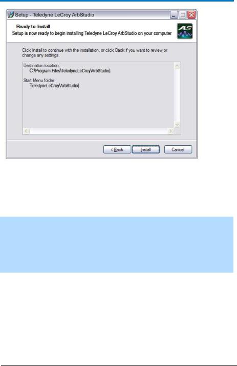
Review the installation summary shown on the Ready to Install screen and click Install when ready.
922244-00 Rev A |
13 |
ArbStudio
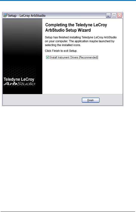
As the installation completes, the Completing the Teledyne LeCroy ArbStudio Setup Wizard screen is shown as follows. This same screen also provides a checkbox (marked by default) to continue the wizard and Install Instrument Drivers. Leave the checkbox marked and proceed by clicking the Finish button.
NOTE: While unmarking the checkbox and clicking the Finish button does complete the software installation, it does not install the necessary system drivers on your computer - making your ArbStudio system inoperable on your computer. This is why it is strongly recommended to leave the Install Instrument Drivers checkbox marked and proceed with the driver installation.
14 |
922244-00 Rev A |
Operator’s Manual
Driver Installation
Click Next to proceed past the Welcome to the Device Driver Installation Wizard screen.
922244-00 Rev A |
15 |

ArbStudio
Select your device on the table shown in the Completing the Device Driver Installation Wizard screen and click the Finish button.
16 |
922244-00 Rev A |
Operator’s Manual
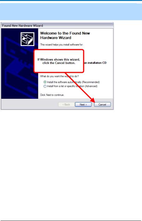
NOTE: If Windows shows the Found New Hardware Wizard, click Cancel. Only use the ArbStudio Software and Driver installation procedure to configure your system.
Now, with correct application software, drivers, and the latest .NET Framework installed, your ArbStudio is ready for use.
Initial ArbStudio Software Interfaces
The ArbStudio software environment provides access to all product functions. The interface allows you to control up to eight devices connected by the Expansion Bus Cable configuring them as Arbitrary Waveform Generators, Digital Pattern Generators, or Mixed Mode Generators.
ArbStudio Workspace
The ArbStudio software workspace consists of two main elements:
The main document editing area, shown on the right side on the following screen-shot.
The ArbStudio Control Navigation Tree, shown on the left side on the following screen-shot.
922244-00 Rev A |
17 |
ArbStudio
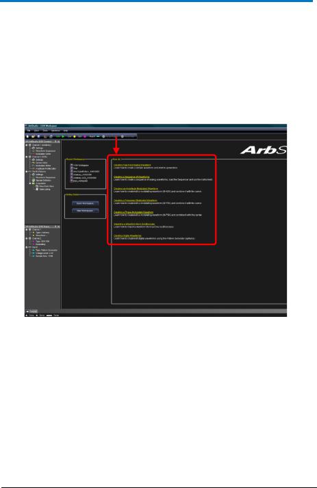
As mentioned, when you open the ArbStudio environment, the most common initial tasks are displayed on the Welcome screen for easy selection in a special view, called the How do I section.
The common tasks include the following:
"How do I" Scenario Details (on page 146)
Recent Workspaces
Open Workspace..
New Workspace..
18 |
922244-00 Rev A |

Operator’s Manual
Interface and Display
The user interface is shown when you open an existing project or create a new one. Numbered callouts on this image correspond with the following interface section descriptions.
1.Menu Bar - Provides drop-down menu access to device functions, workspace, window management, and online help.
2.Toolbar - Various functions including channel/pod selection, device setup and instrument start/stop are made available as icons in this area.
New Workspace - creates a new workspace.
Open Workspace - opens an existing workspace.
922244-00 Rev A |
19 |

ArbStudio
Save Workspace - saves newly-created or edited workspaces.
System Setup - selects the Master/Slave channel when multiple devices are connected by the expansion bus or when you want channels managed by an event.
Device Setup - accesses more detailed ArbStudio option settings.
RUN/STOP - first loads setting parameters and the waveforms into the instrument, and then it starts/stops the waveform generation for all enabled channels selected from the Channels Selection button.
Ch(1, 2, 3, 4) - selects Channel - You can use this
Pod x - activates or deactivates the RUN/STOP command for the specified Pod. This control is only
available when the Digital Pattern option is enabled.
Force Trigger - makes the instrument generate an internal trigger signal and forces a start event on the selected channels/pods.
Force Stop - forces a stop event on the selected channels/pods.
3.Editing Area - This main display area shows the waveforms selected from the Project Waveform List or Sequencer Window. You can also create/edit waveforms and load the Sequencer from this location.
4.Device Control Tree - The Device Control (navigation) tree provides access to channel settings and tools to edit standard/modulating waveforms, set the amplitude profile of the modulated signal, and load the sequencer.
20 |
922244-00 Rev A |

Operator’s Manual
The icon associated to the channel string indicates if it is master or slave, respectively.
The following icons are used based on Arbitrary or DDS mode selection.
|
|
Arbritrary |
DDS |
Settings |
Settings |
Waveform Sequencer |
Carrier Editor |
Modulation Editor |
Modulation Editor |
|
Amplitude Profile Editor |
Settings - This tool allows setting the sampling rate prescaler, the impedance output, the run mode (Single, Continuous, Burst), and the external control signals (trigger IN, trigger OUT).
922244-00 Rev A |
21 |
ArbStudio
Waveform Sequencer - This tool, available only in the Arbitrary mode, allows you to edit the waveforms loaded in the channel and to select generation order and number of repetitions. The waveforms generated by this tool are considered as carrier signals if the modulation is needed.
Modulation Editor - This tool allows editing a modulating waveform. The signal edited can modulate the waveform edited by the Waveform Editor tool, with a M-ASK, M-FSK or M-PSK modulation law.
Amplitude Profile Editor - This tool, available only in DDS mode, allows setting the amplitude profile of the modulated signal as a function of the frequency.
Carrier Editor - This tool, available only in DDS mode, allows editing the carrier waveform of the modulated signal.
5.Editing Area Tag - These tags conserve screen space by toggling the display of your open waveforms.
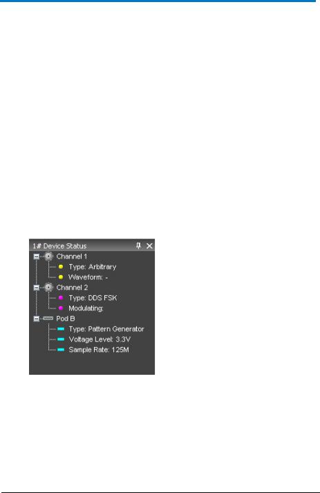
6.Device Status Tree - Lists various channel/pod instrument properties such as sampling rate, channel type, and voltage level.
Type - Shows the channel functionality (Arbitrary, DDS, Digital Pattern).
Waveform - In Arbitrary mode, it shows the current waveform generated by the instrument.
Modulating - In DDS mode, it shows the phase or the frequency of the modulating signal.
Voltage Level - Displays the Pod voltage level.
Sample Rate - The Sample rate of the Digital Pattern
Generator.
22 |
922244-00 Rev A |
 Loading...