

Teledyne Lecroy HVD3000 Series, HVD3102, HVD3106, HVD3106-6M Operator's Manual

Operator's Manual
HVD3000 Series
High-Voltage
Differential Probes


HVD3000 Series
High-Voltage Differential Probes
Operator's Manual
July, 2015

HVD3000 Series High-Voltage Differential Probes Operator's Manual
© 2015 Teledyne LeCroy, Inc. All rights reserved.
Unauthorized duplication of Teledyne LeCroy documentation materials other than for internal
sales and distribution purposes is strictly prohibited. However, clients are encouraged to
duplicate and distribute Teledyne LeCroy documentation for their own internal educational
purposes.
Teledyne LeCroy is a trademark of Teledyne LeCroy, Inc. Other product or brand names are
trademarks or requested trademarks of their respective holders. Information in this
publication supersedes all earlier versions. Specifications are subject to change without notice.
925782-00
July, 2015

Contents
Introduction 1
Safety 2
Voltage Derating for HVD3000 Accessories 4
HVD310x Probes 5
HVD310x Probe Kit 5
HVD310x Specifications 7
HVD3206 Probe 12
HVD3206 Probe Kit 12
HVD3206 Specifications 13
HVD3605 Probe 16
HVD3605 Probe Kit 16
HVD3605 Specifications 17
Functional Test Procedure 20
Performance Verification Procedure 21
Required Equipment 21
Preliminary Procedure 22
Certification Procedure 22
Checking Probe Attenuation in XStream Browser 23
HVD3000 Test Record 24
Operation 25
Connecting to the Test Instrument 25
Connecting to the Test Circuit 25
Operating with an Oscilloscope 26
Maintenance 29
Cleaning 29
Calibration Interval 29
Service Strategy 29
Replacement Parts 29
Returning a Product for Service 30
Contact Us 31
Reference 32
Common Mode Rejection Ratio 32
Differential Mode and Common Mode 32
Differential Mode Range and Common Mode Range 33
IEC/EN 61010-031 Definitions 33
i

HVD3000 Series High-Voltage Differential Probes Operator's Manual
Certifications 34
EMC Compliance 34
Safety Compliance 35
Environmental Compliance 35
Warranty 36
ii

Introduction
Introduction
The HVD3000 series high-voltage active differential probes are safe, easy-to-use, and ideally
suited for power electronics applications where the reference potential is elevated from
ground. The probes feature:
l Differential voltage measurement capability in high common-mode environments
(up to 6kVrms)
l Exceptional common-mode rejection ratio (CMRR) across a broad frequency range
l Wide differential voltage range
l High offset voltage capability
l 1% DC and low frequency gain accuracy
l AC or DC coupling
l ProBus interface with automatic scaling
l Auto Zero capabilities
The CMRR for the probes is exceptional out to very high frequencies. This greatly assists in
measuring signals in the noisy, high common-mode environments of power electronics. High
CMRR combined with low probe noise and high offset capability makes the probes capable of
measuring very small control signals floating on high common-mode voltages.
Specifications are provided for using each probe within a wide differential voltage range, and
the probe can be safely operated even above this range. The probes will display signal up to the
measurable differential voltage before the saturation limit, although the specifications cannot
be guaranteed. Within the specified range, the probe is operating below the saturation point of
the amplifier, and very reasonable results can be expected.
The probes are calibrated for high-precision measurements to within 1% at DC to low
frequency (~10 kHz). This provides for high accuracy of top and base voltage levels of pulsewidth modulated signals. The AutoZero capability permits further measurement precision by
allowing small offset drifts to be calibrated out of the measurement.
All HVD3000 probes are compatible with any Teledyne LeCroy oscilloscope equipped with the
ProBus interface. The ProBus interface makes the probe an integral part of the oscilloscope.
Power is provided to the probe through the interface, so there is no need for a separate power
supply or batteries. Attenuation is automatically selected based on the oscilloscope gain range
(V/div) setting, and the offset adjust is unified with that of the oscilloscope (maximum offset
depends on the V/div setting and the oscilloscope model). In general, Teledyne LeCroy 12-bit
High Resolution Oscilloscopes (HRO) and HD4096 High Definition Oscilloscopes (HDO) provide
the most offset capability over the widest range of V/div settings.
The HVD310x probes require XStream™ software version 7.4 or greater. The HVD3206 and
HVD3605 probes require XStream software version 7.8 or greater.
1
HVD3000 Series High-Voltage Differential Probes Operator's Manual
Safety
To maintain the probe in a correct and safe condition, observe generally accepted safety
procedures in addition to the precautions specified in this section. The overall safety of any
system incorporating this product is the responsibility of the assembler of the system.
Symbols
These symbols on the probe and accessories or in documentation to alert you to important
safety considerations.
CAUTION of damage to instrument, or WARNING of hazard to health. Attend to the
accompanying information to protect against personal injury or damage. Do not
proceed until conditions are fully understood and met.
HIGH VOLTAGE WARNING. Risk of electric shock.
Double Insulation
Measurement Ground
Precautions
WARNING. To avoid personal injury or damage due to electric shock or fire:
Do not overload; observe all terminal ratings. Do not apply any potential that exceeds
the maximum rating of the probe and/or the probe accessory, whichever is less.
Comply with the Voltage vs. Frequency derating curve when measuring higher
frequency signals.
Connect and disconnect properly. Always connect the probe input lead to the probe
accessories before connecting to a voltage source. Ensure the connections are secure
before applying voltage. Do not disconnect leads or accessories from a live circuit.
Keep the probe body and output cable away from the circuits being measured. Only
accessory tips are intended for contact with electrical sources.
Use only accessories compatible with the probe. Use only accessories that are rated
for the application. Substituting other accessories than those specified in this manual
may create a shock /burn hazard.
Keep fingers behind the finger guard of the probe accessories.
Do not remove the probe's casing. Touching exposed connections may result in
electric shock.
2

Safety
CAUTION.
Use only as specified. The probe is intended to be used only with compatible Teledyne
LeCroy instruments. Use of the probe and/or the equipment it is connected to in a
manner other than specified may impair the protection mechanisms.
Do not bend cables excessively. The input leads have a jacket wear indicator that
shows through when the jacket is excessively worn. If the white "WEAR" indicator on
the input leads is visible, cease use and contact Teledyne LeCroy service for repair or
replacement.
Use only within the operational environment listed. Do not use in wet or explosive
atmospheres.
Keep product surfaces clean and dry.
Do not operate with suspected failures. Before each use, inspect the probe and
accessories for any damage such as tears or other defects in the probe body, cable
jacket, accessories, etc. If any part is damaged, cease operation immediately and
sequester the probe from inadvertent use.
Operating Environment
Temperature, Operating 0 C to 50 C
Temperature, Non-operating - 40 C to 70 C
Relative Humidity, Operating 5% to 80% RH (Non-Condensing)
45% RH above 30 C
Relative Humidity, Non-operating 5% to 95% RH (Non-Condensing)
75% RH above 30 C
45% RH above 40 C
Altitude 3000 m (9842 ft) max.
Derated to 2000 m (6561 ft.) when used with clip accessories
Usage Indoors
3
HVD3000 Series High-Voltage Differential Probes Operator's Manual
Voltage Derating for HVD3000 Accessories
Accessory Part Number
Derated Max. Input Voltage for
Combined Probe and
Accessory (from either input to
ground) *
Spade Terminals PK-HVA-05 1000 V CAT III
Safety Alligator Clips PK-HVA-01 1000 V CAT III
Plunger Alligator Clips PK-HVA-04 1000 V CAT III
Plunger Pincer Clips PK-HVA-02 1000 V CAT II
Plunger Hook Clips PK-HVA-03 1000 V CAT II
6kV Alligator Clips PK-HVA-06 6000 V CAT I **
1000 Vrms CAT III
1500 Vdc CAT III
* See "IEC/EN 61010-031 Definitions" on page 33.
** CAT I per IEC IEC/EN 61010-031/A1:2008.
"O" (No Rated Measurement Category) per IEC/EN 61010-031:2015.
CAUTION. The operating altitude of the probe is derated to 2000 m (6560 ft) when
used with the accessories above.
WARNING. Each accessory has a different measurement (overvoltage) category
(CAT) rating. The voltage and CAT rating of the probe are derated to the values in the
table above when used with the corresponding accessory.
WARNING. The HVD3206 and HVD3605 probes may be used with the HVD310x
accessories. However, the voltage and CAT rating of the probe are derated to the
values in the table above when used with the corresponding accessory.
WARNING. To avoid risk of electric shock or fire, do not exceed either the voltage
rating or category rating. Keep your fingers behind the finger guard of the probe.
Keep the probe body and output cable away from the circuits being measured. Use
only the specified accessories.
4

HVD310x Probes
HVD310x Probes
HVD310x Probe Kit
HVD310x Probe Kit
The HVD310x probes are delivered with the following:
Item Description Safety Rating* Part Number
‡
QTY
Spade
Terminals
(1)
Designed to connect to terminal
strips, posts and screws, the overall
length is 63 mm (2.48 inches). 4 mm
Banana (female) connector. 1 ea.
red/black.
Insulated
1000 V CAT III
PK-HVA-05 2
Safety
Alligator Clips
(2)
Designed to reliably grip large
components, such as bus bars and
large bolts, the overall length is 92.8
mm (3.65 inches) and the jaw opens
to 32 mm (1.26 inch). Only the lower
jaw is conducive; the top jaw is
insulating plastic. 4 mm Banana
(female) connector.1 ea. red/black.
Insulated
1000 V CAT III
PK-HVA-01 2
5

HVD3000 Series High-Voltage Differential Probes Operator's Manual
Item Description Safety Rating* Part Number
‡
QTY
Plunger
Alligator Clips
(3)
The clip is designed to securely
grasp thick wires, cables, ground
leads, rails, and screw heads. The
overall length is 153 mm (6.02
inches); the jaw opens to 23 mm
(0.905 inch) max. 4 mm Banana
(female) connector. 1 ea. red/black.
Insulated
1000 V CAT III
PK-HVA-04 2
Plunger
Pincer Clips
(4)
Designed with a long, thin, flexible
stem for attaching to hard-to-reach
test points, the entire body is fully
insulated. The overall length is 161.6
mm (6.36 inch). The pincers can grab
leads, pins and wires up to 4 mm
(0.157 inch) in diameter. 4 mm
Banana (female) connector. 1 ea.
red/black.
Insulated
1000 V CAT II
PK-HVA-02 2
Plunger
Hook Clips
(5)
Designed with a flexible stem to
access deep targets in dense
environments and a 4.5 mm (0.177
inch) hook to attach to wire leaded
parts. The overall length is 157.6 mm
(6.20 inches). 4 mm Banana (female)
connector. 1 ea. red/black.
Insulated
1000 V CAT II
PK-HVA-03 2
Case Soft storage case. SAC-01A 1
Foam Custom foam insert for storage case.
HVD3106
924228-00
HVD3106-6M
925473-00
1
Operator's
Manual
NA 1
* See "IEC/EN 61010-031 Definitions" on page 33 for measurement category definitions.
‡ See "Replacement Parts" on page 29 for information about ordering replacement accessories.
NOTE: The HVD310x-NOACC option offers the probe without the accessories.
WARNING. To avoid injury or death due to electric shock, do not handle probe input
leads connected to the Spade Terminals while they are connected to a voltage source.
Do not use Spade Terminals as hand-held accessories; they are meant to be used as a
permanent installation in a test set up.
6

HVD310x Probes
HVD310x Specifications
For the current specifications, see the product datasheet at teledynelecroy.com. Below are
some key product specifications.
Specifications are subject to change without notice.
Guaranteed Specifications
HVD3102 HVD3106 HVD3106-6M
Bandwidth (probe only) 25 MHz 120 MHz 80 MHz
Risetime 10-90 % 14 ns 2.9 ns 4.4 ns
CMRR Test Limits, 23 C 80 db @ 50 Hz
60 db @ 1 MHz
80 db @ 50 Hz
60 db @ 1 MHz
80 db @ 50 Hz
60 db @ 1 MHz
Electrical Characteristics
Max. Rated Diff. Voltage
(between each input)
1500 V (DC + Peak AC)
Max. Measurable Diff. Voltage
(before saturation)
2000 V (DC + Peak AC)
Max. Common Mode Voltage
(from either input to ground)
± 1500 V (DC + Peak AC)
1000 Vrms
Max. Input Voltage to Earth
(from either input to ground)
± 1500 Vpk
Max. Safe Input Voltage *
(per IEC 61010-031)
1000 Vrms CAT III
Pollution Degree * 2
* See "IEC/EN 61010-031 Definitions" on page 33.
Vertical Sensitivity
100 mV/Div to 500 V/Div.
7
HVD3000 Series High-Voltage Differential Probes Operator's Manual
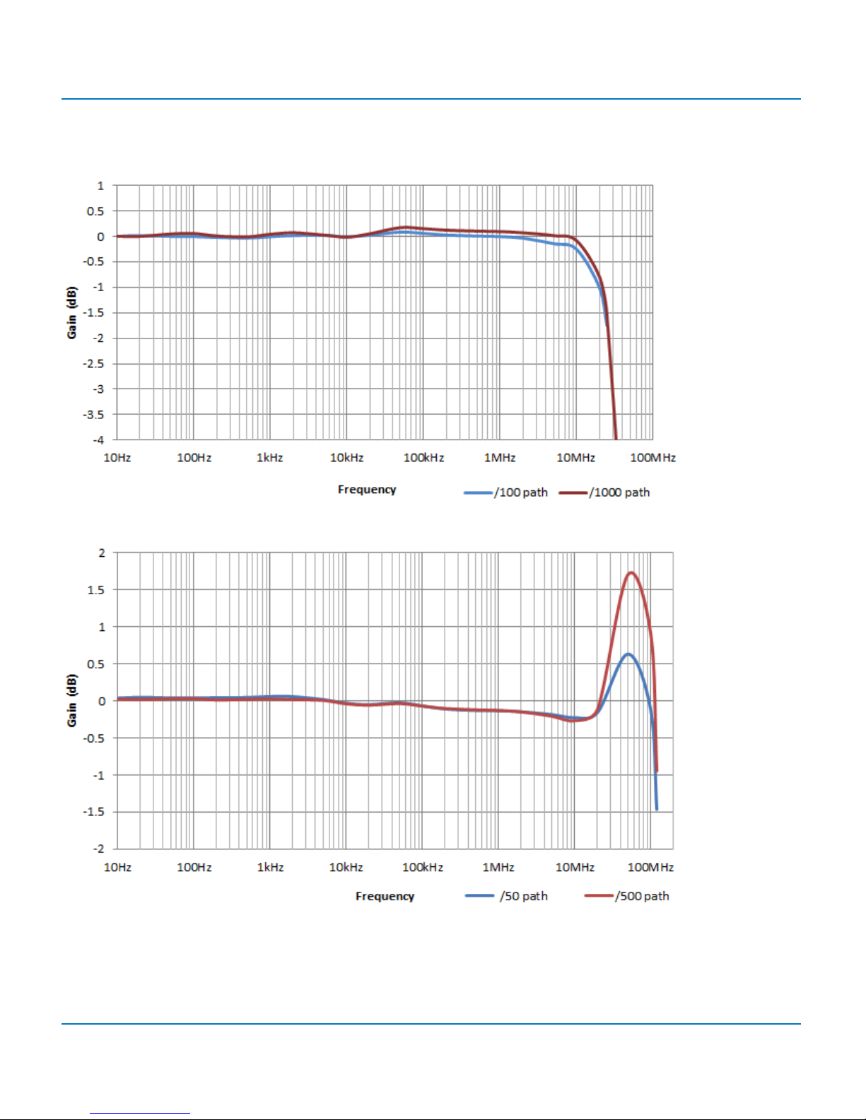
Bandwidth
HVD3102 TYPICAL BANDWIDTH
HVD3106 TYPICAL BANDWIDTH
8
 Loading...