

Teledyne Lecroy HVD3000, HVD3000A Operator's Manual

Operator’s Manual
HVD3000 / HVD3000A
High
Differential Probes
-Voltage
www. .com
information@itm.com1.800.561.8187

Operator’s Manual
Contents
Introduction .................................................................................................................................... 1
Safety .............................................................................................................................................. 3
Voltage Derating for Accessories ................................................................................................. 5
HVD310x and HVD310xA Probes .................................................................................................. 6
HVD3206 and HVD3206A Probes ............................................................................................... 13
HVD3605 and HVD3605A Probes ............................................................................................... 18
Functional Test Procedure .......................................................................................................... 22
Performance Verification Procedure .......................................................................................... 23
Required Equipment ................................................................................................................. 23
Preliminary Procedure.............................................................................................................. 24
Certification Procedure ............................................................................................................ 24
Checking Probe Attenuation in XStreamBrowser ................................................................. 26
HVD3000 / HVD3000A Test Record ........................................................................................ 27
Operation ...................................................................................................................................... 28
Connecting to the Test Instrument ......................................................................................... 28
Connecting to the Test Circuit ................................................................................................. 28
Operating with an Oscilloscope .............................................................................................. 29
Maintenance ................................................................................................................................. 33
Cleaning .................................................................................................................................... 33
Calibration Interval ................................................................................................................... 33
Service Strategy ....................................................................................................................... 33
Replacement Parts ................................................................................................................... 33
Returning a Product for Service .............................................................................................. 34
Technical Support .................................................................................................................... 35
Reference ...................................................................................................................................... 36
Certifications ................................................................................................................................ 39
i
www. .com
information@itm.com1.800.561.8187

HVD3000 / HVD3000A High-Voltage Differential Probes
Warranty
THE WARRANTY BELOW REPLACES ALL OTHER WARRANTIES, EXPRESSED OR IMPLIED,
INCLUDING BUT NOT LIMITED TO ANY IMPLIED WARRANTY OF MERCHANTABILITY, FITNESS, OR
ADEQUACY FOR ANY PARTICULAR PURPOSE OR USE. TELEDYNE LECROY SHALL NOT BE LIABLE
FOR ANY SPECIAL, INCIDENTAL, OR CONSEQUENTIAL DAMAGES, WHETHER IN CONTRACT OR
OTHERWISE. THE CUSTOMER IS RESPONSIBLE FOR THE TRANSPORTATION AND INSURANCE
CHARGES FOR THE RETURN OF PRODUCTS TO THE SERVICE FACILITY. TELEDYNE LECROY WILL
RETURN ALL PRODUCTS UNDER WARRANTY WITH TRANSPORT PREPAID.
The product is warranted for normal use and operation, within specifications, for a period of
one year from shipment. Teledyne LeCroy will either repair or, at our option, replace any
product returned to one of our authorized service centers within this period. However, in
order to do this we must first examine the product and find that it is defective due to
workmanship or materials and not due to misuse, neglect, accident, or abnormal conditions
or operation.
Teledyne LeCroy shall not be responsible for any defect, damage, or failure caused by any
of the following: a) attempted repairs or installations by personnel other than Teledyne
LeCroy representatives, b) improper connection to incompatible equipment, or c) use of
non-Teledyne LeCroy supplies. Furthermore, Teledyne LeCroy shall not be obligated to
service a product that has been modified or integrated where the modification or
integration increases the task duration or difficulty of servicing the product. Spare and
replacement parts and repairs all have a 90-day warranty.
Products not made by Teledyne LeCroy are covered solely by the warranty of the original
equipment manufacturer.
ii
www. .com
information@itm.com1.800.561.8187

Operator’s Manual
Note:
Introduction
The HVD3000 and HVD3000A high-voltage active differential probes are safe, easy-to-use,
and ideally suited for power electronics applications where the reference potential is
elevated from ground. The probes feature:
• Differential voltage measurement capability in high common-mode environments
(up to 6kVrms)
• Exceptional common-mode rejection ratio (CMRR) across a broad frequency range
• Wide differential voltage range
• High offset voltage capability
• 1% DC and low frequency gain accuracy
• AC or DC coupling
• ProBus interface with automatic scaling
• Auto Zero capabilities
The CMRR for the probes is exceptional out to very high frequencies. This greatly assists in
measuring signals in the noisy, high common-mode environments of power electronics.
High CMRR combined with low probe noise and high offset capability makes the probes
capable of measuring very small control signals floating on high common-mode voltages.
The maximum rated differential voltage specifications are provided for using each probe
within a wide differential voltage range. The probes will even display signals above the
maximum rated differential voltage, up to the maximum measurable differential voltage
before saturation limit, although the specifications cannot be guaranteed. Within this range,
the probe is operating below the saturation point of the amplifier, and very reasonable
results can be expected.
HVD3000A probes are fitted with detection circuits that will indicate when the
differential or common mode voltages are beyond the operating ranges of the probe. A
warning will be displayed in the oscilloscope message bar.
The probes are calibrated for high-precision measurements to within 1% at DC to low
frequency (~10 kHz). This provides for high accuracy of top and base voltage levels of
pulse-width modulated signals. The Auto Zero capability permits further measurement
precision by allowing small offset drifts to be calibrated out of the measurement.
1
www. .com
information@itm.com1.800.561.8187

HVD3000 / HVD3000A High-Voltage Differential Probes
The ProBus interface makes the probe an integral part of the oscilloscope. Power is
provided to the probe through the interface, so there is no need for a separate power supply
or batteries. Attenuation may be either automatically selected based on the oscilloscope
gain range (V/div) setting, with the offset adjust unified with that of the oscilloscope, or
locked to the maximum attenuation setting.
Maximum offset depends on the V/div setting and the oscilloscope model. In general,
Teledyne LeCroy 12-bit High Resolution Oscilloscopes (HRO) and HD4096 High Definition
Oscilloscopes (HDO) provide the most offset capability over the widest range of V/div
settings.
Compatibility
HVD3000 and HVD3000A probes are compatible with most Teledyne LeCroy MAUI
oscilloscopes equipped with the ProBus interface. See the HVD3000 product page on our
website for all compatible oscilloscope models.
Some legacy oscilloscopes, such as WavePro 7000A and WaveSurfer XS, can be made
compatible with HVD3000 probes if upgraded to the Windows XP Professional operating
system and requisite firmware. Contact your regional service center regarding upgrades.
Required Firmware
Proper functioning of the HVD3000 and HVD3000A probes requires a minimum version of
the XStreamDSO™ firmware to be installed on the oscilloscope:
• The HVD310x probes require firmware version 7.4.x.x or greater.
• The HVD3206 and HVD3605 probes require firmware version 7.8.x.x or greater.
• All HVD3xxxA probes require firmware version 8.5.1.0 or greater.
2
www. .com
information@itm.com1.800.561.8187
Operator’s Manual
The overall safety of any
system incorporating this product is the responsibility of the assembler of the system.
WARNING, HIGH VOLTAGE. Risk of electric shock or burn.
CAUTION of damage to probe or instrument, or WARNING of hazard to health.
ESD CAUTION. Risk of Elecstostatic Discharge (ESD) that can damage the probe or
WARNING.
Do not overload; observe all terminal ratings.
Comply with the Voltage vs. Frequency derating curve
Connect and disconnect properly
Keep the probe body and output cable away from the circuits being measured.
Use only accessories compatible with the probe.
Safety
To maintain the probe in a correct and safe condition, observe generally accepted safety
procedures in addition to the precautions specified in this section.
Symbols
These symbols appear on the probe and accessories or in this manual to alert you to
important safety considerations.
Attend to the accompanying information to protect against personal injury or
damage. Do not proceed until conditions are fully understood and met.
instrument if anti-static measures are not taken.
Precautions
To avoid personal injury or damage due to electric shock or fire:
Do not apply any potential that exceeds the
maximum rating of the probe and/or the probe accessory, whichever is less.
when measuring higher frequency
signals.
accessories before connecting to a voltage source. Ensure the connections are secure
before applying voltage. Do not disconnect leads or accessories from a live circuit.
accessory tips are intended for contact with electrical sources.
. Always connect the probe input lead to the probe
Only
Use only accessories that are rated for the
application. Substituting other accessories than those specified in this manual may create
a shock /burn hazard.
www. .com
3
information@itm.com1.800.561.8187

HVD3000 / HVD3000A High-Voltage Differential Probes
Keep fingers behind the finger guard of the probe accessories.
Do not remove the probe's casing.
CAUTION.
Use only as specified
Do not bend cables excessively.
Use only within the operational environment listed.
Keep product surfaces clean and dry.
Do not operate with suspected failures.
Temperature, Operating
Temperature, Non-operating
Relative Humidity, Operating
Relative Humidity, Non-operating
Altitude
Usage
Touching exposed connections may result in electric
shock or burn.
To prevent damage to the equipment:
. The probe is intended to be used only with compatible Teledyne
LeCroy instruments. Use of the probe and/or the equipment it is connected to in a manner
other than specified may impair the protection mechanisms.
atmospheres.
for any damage such as tears or other defects in the probe body, cable jacket, accessories,
etc. If any part is damaged, cease operation immediately and sequester the probe from
inadvertent use.
Operating Environment
0 C to 50 C
40 C to 70 C
5% to 80% RH (Non-Condensing)
5% to 95% RH (Non-Condensing)
3000 m (9842 ft.) max.
Indoors
Do not use in wet or explosive
Before each use, inspect the probe and accessories
45% RH above 30 C
75% RH above 30 C
45% RH above 40 C
Derated to 2000 m (6561 ft.)
when used with clip accessories
4
www. .com
information@itm.com1.800.561.8187

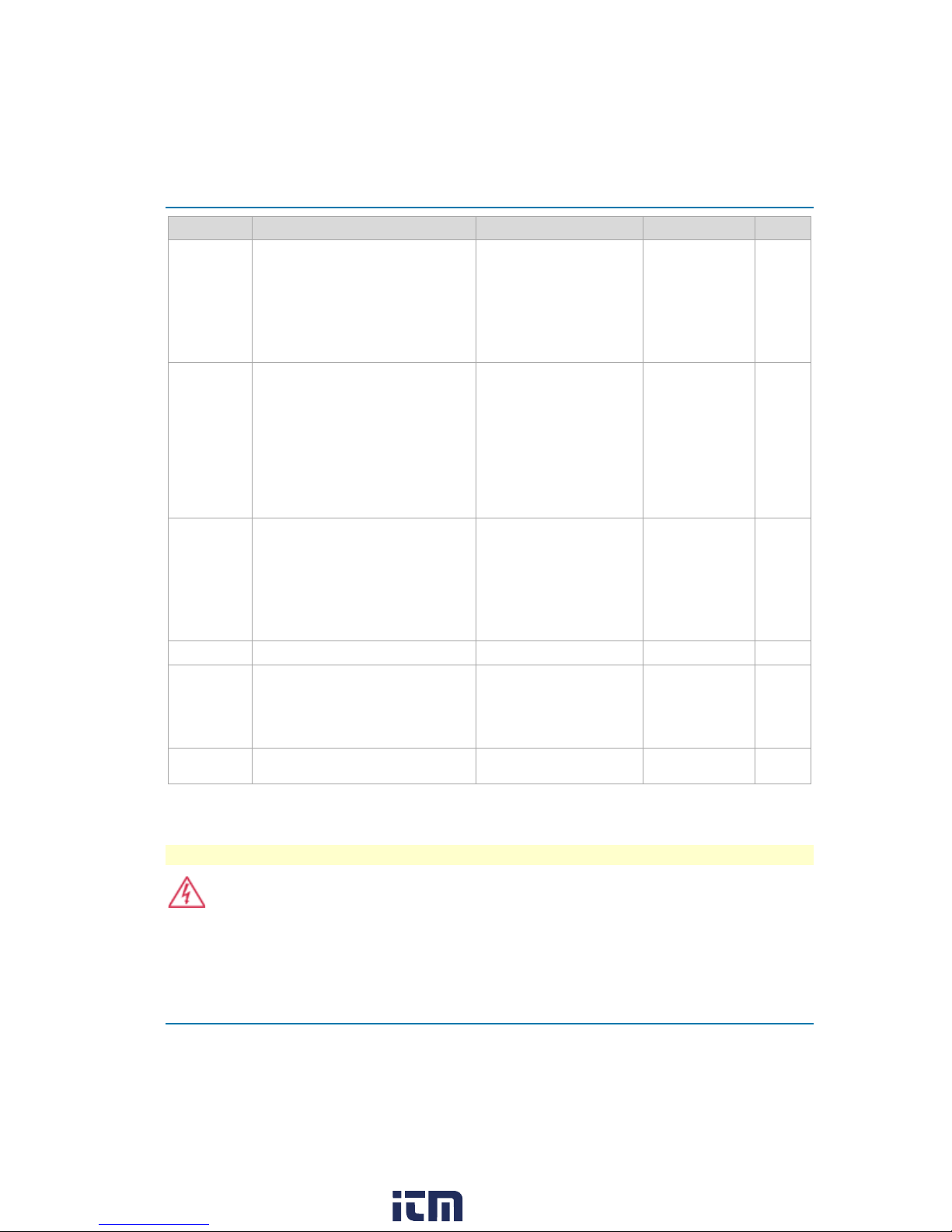
Voltage Derating for Accessories
(either input to ground)*
Plunger Pincer Clips
PK-HVA-02
1000 V CAT II
Plunger Hook Clips
PK-HVA-03
1000 V CAT II
1500 Vdc CAT III
CAUTION.
WARNING.
WARNING.
WARNING.
Operator’s Manual
Accessory Part Number
Spade Terminals PK-HVA-05 1000 V CAT III
Safety Alligator Clips PK-HVA-01 1000 V CAT III
Plunger Alligator Clips PK-HVA-04 1000 V CAT III
6kV Alligator Clips PK-HVA-06
2kV Plunger Alligator Clips PK-HVA-07
* See "IEC/EN 61010-031 Definitions" on p.38.
** CAT I per IEC/EN 61010-031/A1:2008. No Rated Measurement Category per IEC/EN 61010-031:2015.
Derated Max. Input Voltage for
Combined Probe & Accessory
6000 V CAT I **
1000 Vrms CAT III
2000 V (DC + Peak AC) CAT I **
1000 Vrms CAT III
1500 Vdc CAT III
The operating altitude of the probe is derated to 2000 m (6560 ft) when
used with the above accessories.
Each accessory has a different measurement (overvoltage) category
(CAT) rating. The voltage and CAT rating of the probe are derated to the values in
the table above when used with the corresponding accessory.
While all probes may be used with the HVD310x accessories (spade
terminals, plunger clips, etc.), the voltage and CAT ratings of the probe are derated
to the values in the table above when used with the corresponding accessory.
To avoid risk of electric shock or fire, do not exceed either the voltage
rating or category rating. Keep your fingers behind the finger guard of the probe.
Keep the probe body and output cable away from the circuits being measured. Use
only the specified accessories.
www. .com
5
information@itm.com1.800.561.8187

HVD3000 / HVD3000A High-Voltage Differential Probes
HVD310x and HVD310xA Probes
Probe Kit
The probes are delivered with the following:
Item Description Safety Rating* Part Number QTY
Spade
Terminals
(1)
Safety
Alligator
Clips
(2)
Designed to connect to terminal
strips, posts and screws, the overall
length is 63 mm (2.48 inches). 4 mm
Banana (female) connector. 1 ea.
red/black.
Designed to reliably grip large
components, such as bus bars and
large bolts, the overall length is 92.8
mm (3.65 inches) and the jaw opens
to 32 mm (1.26 inch). Only the lower
jaw is conducive; the top jaw is
insulating plastic. 4 mm Banana
(female) connector.1 ea. red/black.
Insulated 1000 V CAT III PK-HVA-05 2
Insulated 1000 V CAT III PK-HVA-01 2
6
www. .com
information@itm.com1.800.561.8187
Operator’s Manual
NOTE:
WARNING.
Item Description Safety Rating* Part Number QTY
Plunger
Alligator
Clips
(3)
Plunger
Pincer Clips
(4)
Plunger
Hook Clips
(5)
Case
Foam
Operator's
Manual
The clip is designed to securely
grasp thick wires, cables, ground
leads, rails, and screw heads. The
overall length is 153 mm (6.02
inches); the jaw opens to 23 mm
(0.905 inch) max. 4 mm Banana
(female) connector. 1 ea. red/black.
Designed with a long, thin, flexible
stem for attaching to hard-to-reach
test points, the entire body is fully
insulated. The overall length is 161.6
mm (6.36 inch). The pincers can
grab leads, pins and wires up to 4
mm (0.157 inch) in diameter. 4 mm
Banana (female) connector. 1 ea.
red/black.
Designed with a flexible stem to
access deep targets in dense
environments and a 4.5 mm (0.177
inch) hook to attach to wire leaded
parts. The overall length is 157.6
mm (6.20 inches). 4 mm Banana
(female) connector. 1 ea. red/black.
Soft storage case. SAC-01A 1
Custom foam insert for storage
case.
NA 1
Insulated 1000 V CAT III PK-HVA-04 2
Insulated 1000 V CAT II PK-HVA-02 2
Insulated 1000 V CAT II PK-HVA-03 2
HVD3106
924228-00
HVD3106-6M
925473-00
1
* See "IEC/EN 61010-031 Definitions" on p.38 for measurement category definitions.
‡ See "Replacement Parts" on page 32 for information about ordering replacement accessories.
The *-NOACC options offer the probe without the accessories.
To avoid injury or death due to electric shock, do not handle probe input
leads connected to the Spade Terminals while they are connected to a voltage
source. Do not use Spade Terminals as hand-held accessories; they are meant to
be used as a permanent installation in a test set up.
www. .com
7
information@itm.com1.800.561.8187

HVD3000 / HVD3000A High-Voltage Differential Probes
HVD3102
HVD3102A
HVD3106
HVD3106A
HVD3106
HVD3106A
Bandwidth (probe only)
25 MHz
120 MHz
80 MHz
Risetime 10-90 %
14 ns
2.9 ns
4.4 ns
CMRR Test Limits, 23 C
80 db @ 50 Hz
60 db @ 1 MHz
80 db @ 50 Hz
60 db @ 1 MHz
80 db @ 50 Hz
60 db @ 1 MHz
Max. Rated Diff. Voltage
(between each input)
1500 V (DC
Max. Measurable Diff. Voltage
(before saturation)
2000 V (DC
Max. Common Mode Voltage
(
± 1500 V (DC
1000 Vrms
Max. Input Voltage to Earth
(
± 1500 Vpk
Max. Safe Input Voltage*
(per IEC 61010
1000 Vrms CAT III
Pollution Degree *
2
HVD310x / HVD310xA Specifications
For the current specifications, see the product datasheet a Below are
some key product specifications.
Specifications are subject to change without notice.
GUARANTEED SPECIFICATIONS
/
/
-6M/
-6M
ELECTRICAL CHARACTERISTICS (ALL PROBES)
+ Peak AC)
+ Peak AC)
either input to ground)
either input to ground)
-031)
* See "IEC/EN 61010-031 Definitions" on p.38.
VERTICAL SENSITIVITY (ALL PROBES)
100 mV/Div to 500 V/Div.
+ Peak AC)
8
www. .com
information@itm.com1.800.561.8187

HVD310x / HVD310xA Bandwidth
HVD3102 / HVD3102A TYPICAL BANDWIDTH
HVD3106 / HVD3106A TYPICAL BANDWIDTH
Operator’s Manual
www. .com
9
information@itm.com1.800.561.8187

HVD3000 / HVD3000A High-Voltage Differential Probes
HVD3106-6M / HVD3106A-6M TYPICAL BANDWIDTH
10
www. .com
information@itm.com1.800.561.8187
 Loading...