

Teledyne TIENet 310 Ex Installation And Operation Manual
TIENet® 310 Ex
Ultrasonic Level Sensor
Installation and Operation Guide
Ultrasonic Level Sensor
Manual Body #69-4313-010
Copyright © 2012. All rights reserved, Teledyne Isco
Revision E, March 2019


Foreword
This instruction manual is designed to help you gain a thorough understanding of the operation of
the equipment. Teledyne ISCO recommends that you read this manual completely before placing
the equipment in service.
Although Teledyne ISCO designs reliability into all equipment, there is always the possibility of a
malfunction. This manual may help in diagnosing and repairing the malfunction.
If a problem persists, call or e-mail Teledyne ISCO technical support for assistance. Simple
difficulties can often be diagnosed over the phone. For faster service, please have your serial
number ready.
If it is necessary to return the equipment to the factory for service, please follow the shipping
instructions provided by technical support, including the use of the Return Material
Authorization (RMA) specified. Be sure to include a note describing the malfunction. This will
aid in the prompt repair and return of the equipment.
Teledyne ISCO welcomes suggestions that would improve the information presented in this
manual or enhance the operation of the equipment itself.
Teledyne ISCO is continually improving its products and reserves the right to change
product specifications, replacement parts, schematics, and instructions without notice.
Contact Information
Customer Service
Phone: (800) 228-4373 (USA, Canada, Mexico)
Fax: (402) 465-3022
Email: isco.orders@teledyne.com
Technical Suppor t
Phone: Toll Free (866) 298-6174 (Samplers and flowmeters)
Email: iscoEPS@teledyne.com
Return equipment to: 4700 Superior Street, Lincoln, NE 68504-1398
Other Correspondence
Mail to: P.O. Box 82531, Lincoln, NE 68501-2531
Email: IscoInfo@teledyne.com
(402) 464-0231 (Outside North America)
EAR-Controlled Technology Subject to Restrictions Contained on the Cover Page.


TIENet™ Model 310 Ex Ultrasonic Level Sensor
Safety
TIENet™ Model 310 Ex Ultrasonic Level Sensor
Safety
General Warnings Before installing, operating, or maintaining this equipment, it is
imperative that all hazards and preventive measures are fully
understood. While specific hazards may vary according to
location and application, take heed of the following general
warnings:
WARNING
Avoid hazardous practices! If you use this instrument in
any way not specified in this manual, the protection
provided by the instrument may be impaired.
AVERTISSEMENT
Éviter les usages périlleux! Si vous utilisez cet instrument
d’une manière autre que celles qui sont specifiées dans ce
manuel, la protection fournie de l’instrument peut être
affaiblie; cela augmentera votre risque de blessure.
Hazard Severity Levels This manual applies Hazard Severity Levels to the safety alerts,
These three levels are described in the sample alerts below.
CAUTION
Cautions identify a potential hazard, which if not avoided, may
result in minor or moderate injury. This category can also warn
you of unsafe practices, or conditions that may cause property
damage.
WARNING
Warnings identify a potentially hazardous condition, which
if not avoided, could result in death or serious injury.
DANGER
DANGER – limited to the most extreme situations
to identify an imminent hazard, which if not
avoided, will result in death or serious injury.
v

TIENet™ Model 310 Ex Ultrasonic Level Sensor
Safety
Hazard Symbols The equipment and this manual use symbols used to warn of
hazards. The symbols are explained below.
Hazard Symbols
Warnings and Cautions
The exclamation point within the triangle is a warning sign alerting you of
important instructions in the instrument’s technical reference manual.
The lightning flash and arrowhead within the triangle is a warning sign alerting you of “dangerous voltage” inside the product.
Symboles de sécurité
Ce symbole signale l’existence d’instructions importantes relatives au produit dans ce manuel.
Ce symbole signale la présence d’un danger d’électocution.
Warnungen und Vorsichtshinweise
Advertencias y Precauciones
Das Ausrufezeichen in Dreieck ist ein Warnzeichen, das Sie darauf
aufmerksam macht, daß wichtige Anleitungen zu diesem Handbuch
gehören.
Der gepfeilte Blitz im Dreieck ist ein Warnzeichen, das Sei vor “gefährlichen
Spannungen” im Inneren des Produkts warnt.
Esta señal le advierte sobre la importancia de las instrucciones del manual
que acompañan a este producto.
Esta señal alerta sobre la presencia de alto voltaje en el interior del
producto.
vi

TIENet™ Model 310 Ex
Ultrasonic Level Sensor
Table of Contents
Section 1 Introduction
1.1 Description......................................................... 1-1
1.2 310 Ex Sensor Design ................................................ 1-2
1.3 Operation ..........................................................1-2
1.4 Technical Specifications .............................................. 1-3
1.5 Accessories .........................................................1-4
1.5.1 Ordering Information ..........................................1-4
1.5.2 TIENet 310 Ex Ultrasonic Level Sensor ...........................1-5
Section 2 Installation and Setup for Signature
2.1 Sensor Installation Considerations ..................................... 2-1
2.1.1 Beam Angle ..................................................2-1
2.1.2 Humidity ....................................................2-1
2.1.3 Surface ......................................................2-1
2.1.4 Temperature ..................................................2-1
2.1.5 Waves .......................................................2-2
2.1.6 Wind ........................................................2-2
2.1.7 Hazardous Locations ...........................................2-2
2.2 Connecting the Cable ................................................2-2
2.2.1 Permanent Meters ............................................. 2-2
2.2.2 Connecting to Signature Portable via a TIENet Receptacle ............ 2-5
2.3 Sensor Installation ..................................................2-6
2.3.1 Dead Band ...................................................2-7
2.3.2 Submersion and Fouling ........................................2-7
2.3.3 Mounting Options ............................................. 2-7
2.4 Installation in Hazardous Locations ....................................2-8
2.4.1 Important Information Regarding “X” Marking .....................2-9
2.4.2 Electrical Requirements ....................................... 2-10
2.4.3 Ambient Environment .........................................2-10
2.5 Configuring the System ............................................. 2-14
2.5.1 Updating the Device List .......................................2-14
2.5.2 Measurement Setup ........................................... 2-16
2.6 Level Calibration ................................................... 2-17
2.7 Firmware Updates .................................................2-18
2.8 Troubleshooting TIENet 310 Ex USLS .................................2-18
2.9 Contact Teledyne Isco ...............................................2-18
A.1 Replacement Parts ..................................................A-1
A.1.1 TIENet 310 Ex Ultrasonic Level Sensor Replacement Parts ...........A-2
vii

TIENet™ Model 310 Ex Ultrasonic Level Sensor
Table of Contents
List of Figures
1-1 Basic Signature monitoring system with 310
(mounting hardware not shown) ....................................... 1-1
1-2 310 Ultrasonic TIENet Sensor with unterminated leads (l) or TIENet plug (r) . . 1-2
2-1 TIENet Device terminal strips ........................................ 2-3
2-2 Installing cable with a cord-grip fitting ................................. 2-3
2-3 TIENet Device terminal connections ...................................2-4
2-4 Attach wired terminal strip to case board socket .......................... 2-4
2-5 Position and secure the cable ..........................................2-5
2-6 How to connect a TIENet plug to the Signature Portable ...................2-6
2-7 Sensor mounting options .............................................2-8
2-8 Sensor labeling regarding hazloc installations ...........................2-11
2-9 Hazardous Location Installation Control Drawing-Atex ...................2-12
2-10 Hazardous Location Installation Control Drawing-CSA ..................2-13
2-11 Character grid ...................................................2-14
2-12 Menu Tree: 310 Configuration ....................................... 2-15
2-13 Configuring ultrasonic level measurement .............................2-16
2-14 Ultrasonic level adjustment and calibration ...........................2-17
viii
TIENet® Model 310 Ex
Ultrasonic Level Sensor
Section 1 Introduction
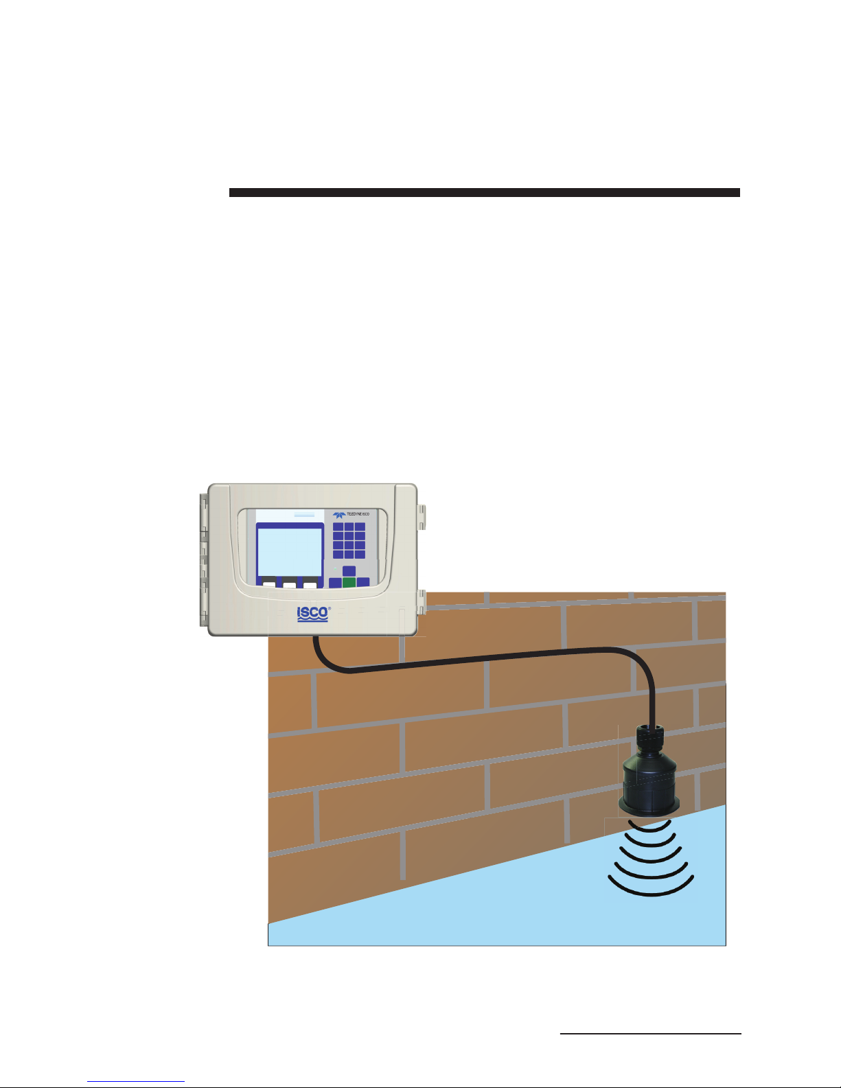
The Signature® Flow Meter uses the TIENet 310 Ex Device to
provide non-contact liquid level measurement. The flow meter
has built-in level-to-flow conversions that cover the majority of
open channel flow measurement situations.
1.1 Description The ultrasonic sensor is mounted over the flow stream. The flow
meter measures the time interval between transmission of a
sound pulse from the sensor, and receiving its echo off the surface
of the liquid, to determine the level of the stream.
Signature Flow Meter
Figure 1-1 Basic Signature monitoring system with
310 Ex (mounting hardware not shown)
310 Ex TIENet Sensor
1-1
TIENet® Model 310 Ex Ultrasonic Level Sensor
Section 1 Introduction
This non-contact measurement method reduces the frequency of
maintenance, and is ideal for applications where the flow may
contain chemicals, grease, silt, or suspended solids.
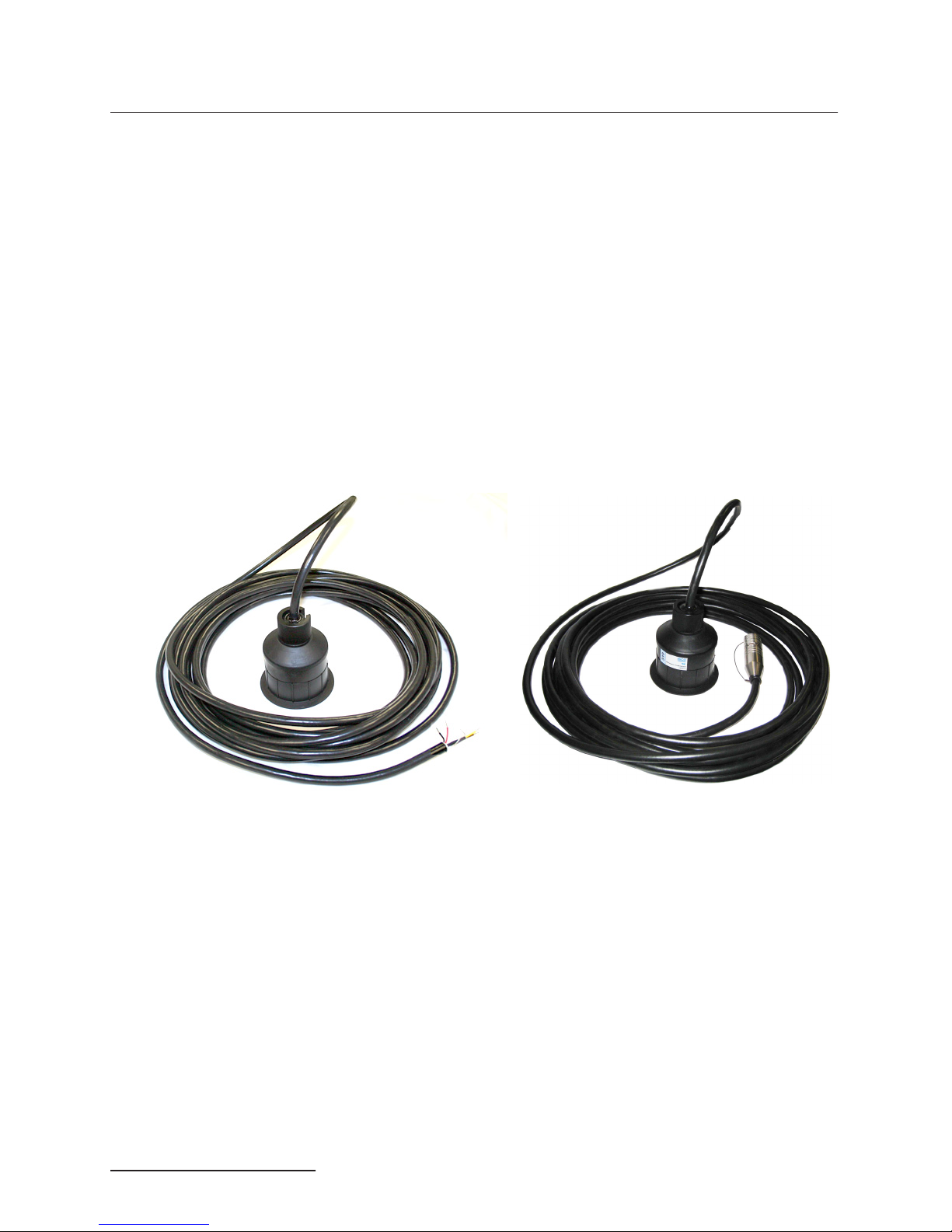
1.2 310 Ex Sensor Design The ultrasonic level sensor consists of a housing with a single
transducer that is both pulse transmitter and echo receiver. A
temperature sensor within the housing measures the ambient
temperature, and a microprocessor automatically compensates
for speed-of-sound changes due to any changes in air temperature.
The 310 Ex is available with a 10m, 23m, and special order to
150m or less cable lengths with or without connectors. For
greater distances, external connection via conduit, and connection of additional TIENet devices, the TIENet Expansion Box
is available. Bulk TIENet cable may also be used for greater distances.
Figure 1-2 310 Ex Ultrasonic TIENet Sensor with
unterminated leads (l) or TIENet plug (r)
1.3 Operation The sensor emits multiple ultrasonic pulses per second. Between
1-2
pulses, the transducer switches from transmitter to receiver.
When the transducer receives the echo from the water’s surface,
the sound energy is converted into an electrical signal. The
signal is then amplified and processed by the Signature flow
meter into an “echo-received” signal. The time between the transmitted pulse and the echo-received signal is proportional to the
distance between the transducer and the liquid surface. This distance in turn determines the liquid level used to calculate flow.

TIENet® Model 310 Ex Ultrasonic Level Sensor
Section 1 Introduction
1.4 Technical
Specifications
Table 1-1 310 Ex TIENet Device Specifications
Sensor Dimensions 3.63" x 4" tall (9.1cm x 10.2cm tall)
Cable Length 10 or 23 meters standard (32.8 or 75.5ft) standard
3
Mounting Attachment
Weight 4 lbs (1.8 kg)
Body Material PVDF
Enclosure IP68 when connected and properly sealed with cord-grip fitting.
Temperature Range
Operating (compensated)
Storage
Hazardous Locations
/4" NPT Pipe thread nipple w/ Conduit lock nut
-22 to 140°F (-30 to 60°C)
-40 to 158°F (-40 to 70°C)
-40 to 140°F (-40 to 60°C)
a
Measurement Range Minimum: 1 ft (0.3m) from sensor to liquid surface
Measurement Accuracy
at 72 °F (22 °C)
Temperature Coefficient within compensated
range
Beam Angle 10° 5° From center line
Ultrasonic Signal 50KHz
Certifications Group II, Category 1G (zone 0), T4
a. All specifications are subject to change without notice.
Maximum: 11 ft (3.3m) from sensor to liquid at minimum level
±0.02ft (0.006m) at 1ft level change or less;
±0.03ft (0.009m) at greater than 1ft level change
± 0.0002 x D (m) per degree C
± 0.00011 x D (ft) per degree F
(Where D is the distance from the transducer to the liquid surface)
Class I, Division 1 (and Zone 0), T4
1-3

TIENet® Model 310 Ex Ultrasonic Level Sensor
Section 1 Introduction
1.5 Accessories Accessories used in sensor installation are briefly described
below. Refer to the next section for ordering information.
Note
Only the Wall Mount Bracket is approved for use in classified
hazardous locations. Other accessories must undergo a hazardous location evaluation in order to fulfill safe installation
requirements.
Spreader Bar – The Spreader Bar is an expandable pipe for
suspending equipment inside a manhole. Outward spring
pressure secures it against the manhole walls, like a shower
curtain rod. Depending on your application, you can then
suspend the 310 Ex TIENet Device, or the Signature Flow Meter
itself, from the bar.
Cable Straightener – The cable straightener is designed for
use in installations where the transducer is suspended by its
cable only, such as from the Spreader Bar. The straightener helps
hold the transducer vertically plumb, thereby stabilizing
alignment.
Cable Clamp – The cable clamp is used with the Spreader Bar
to secure the mounting of the sensor.
Wall Mount Bracket – This device lets you install the ultrasonic level sensor on a convenient nearby wall over a flow
stream, such as the side of a bridge, or other structure.
Floor Mount – The Ultrasonic Floor Mount is a collapsible
metal stand attached to the floor, for extending the sensor out
over a flow stream.
Ultrasonic Calibration Target – This option is designed to
make calibration of the level sensor more accurate during the
installation process by letting you calibrate the level sensor from
outside the manhole.
Sunshade – The ultrasonic sunshade is a white plastic cap that
fits over the top of the ultrasonic transducer. Its purpose is to
keep sunlight from heating the body of the level transducer and
introducing temperature errors to the internal temperature compensation.
1.5.1 Ordering Information Options and accessories can be purchased by contacting Teledyne
1-4
Isco’s Customer Service Department.
Teledyne Isco
Customer Service Dept.
P.O. Box 82531
Lincoln, NE 68501 USA
Phone: 800 228-4373
402 464-0231
FAX: 402 465-3022
E-mail:IscoInfo@teledyne.com
TIENet® Model 310 Ex Ultrasonic Level Sensor
Section 1 Introduction
1.5.2 TIENet 310 Ex
Ultrasonic Level
Sensor
310 Ex Ultrasonic Level Sensor with Signature connection ending in unterminated leads.
For use with Signature 6 position plug-in (green) terminal strip.
Includes cord grip and sensor with cable. (See cable lengths below).
310 Ex Ultrasonic sensor w/ 10m cable................................................................................... 60-4314-005
310 Ex Ultrasonic sensor w/ 23m cable................................................................................... 60-4314-006
310 Ex Ultrasonic sensor Cut-to-length.................................................................................. 60-4314-014
Cut to length cable up to 999 ft* ............................................................................................. 60-4304-050
*Cable lengths can go up to 150 m with an expansion box.
310 Ex Ultrasonic Level Sensor with Signature connection ending in TIENet plug. For use
with portable Signature TIENet receptacle.
Includes cord grip and sensor with cable. (See cable lengths below).
310 Ex Ultrasonic sensor w/ connector and 10m cable .......................................................... 60-4314-009
310 Ex Ultrasonic sensor w/ connector and 23m cable .......................................................... 60-4314-011
310 Ex Ultrasonic sensor w/ connector Cut-to-length*. ......................................................... 60-4314-013
Cable Assembly with TIENet Y w/ connector ......................................................................... 60-4304-066
*Cable lengths can go up to 150 m with an expansion box.
Sunshade for ultrasonic sensor ............................................................................................... 60-3004-142
Spreader bar for suspension of sensor or flow meter in manhole shaft ................................ 60-3004-110
Cable clamp .............................................................................................................................. 60-3004-129
Sensor Mounting Bracket U/S ................................................................................................. 60-2003-615
Floor mount for horizontal surfaces ........................................................................................60-2004-611
Cable straightener for suspension over stream...................................................................... 60-4313-009
Ultrasonic calibration target ................................................................................................... 60-3004-143
TIENet Expansion Box............................................................................................................. 60-4307-023
Kit includes 10ft TIENet cable
Cord grip fitting,3/4" NPT, for TIENet cable ........................................................................... 209-0073-12
Barrier for Signature (SPA 2060) ............................................................................................60-5324-060
Note
Teledyne Isco uses FreeRTOS version 5.4.2 in its TIENet
devices. In accordance with the FreeRTOS license, FreeRTOS
source code is available on request. For more information, visit
www.FreeRTOS.org.
1-5
 Loading...