

Teledyne THCD-101 Instruction Manual
INSTRUCTION MANUAL
ISO 9001
CERTIFIED
www.teledyne-hi.com
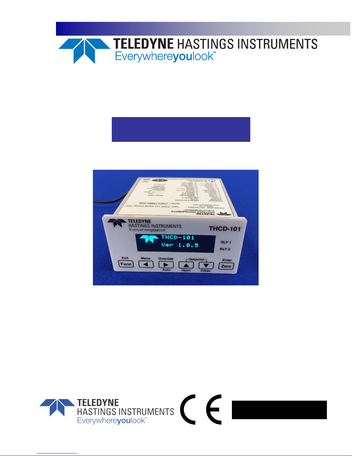
THCD-101
Manual Print History
The print history shown below lists the printing dates of all revisions created for this manual. The revision level
letter increases alphabetically as the manual undergoes subsequent updates. Each new revision includes a
revised copy of this print history page.
Revision A (Document Number 181-122018) ................................................................................ December 2018
Visit www.teledyne-hi.com for WEEE disposal guidance.
Description of Symbols and Messages used in this manual
WARNING: indicates a hazardous situation, which, if not avoided, could result in death or
serious injury. Do not proceed beyond a WARNING notice until the indicated conditions are
fully understood.
CAUTION: indicates a hazardous situation, which if not avoided, could result in minor or
moderate injury. Do not proceed beyond a CAUTION notice until the indicated conditions are
fully understood and met.
NOTICE: calls attention to a procedure or practice that if not correctly performed or adhered
to, could result in equipment damage, loss of data, or inaccurate data.
NOTE: is used for tips and other digressions.
Hastings Instruments reserves the right to change or modify the design of its equipment without any obligation
181-122018_THCD-101 Instruction Manual Page 2 of 26
to provide notification of change or intent to change.

Table of Contents
1. GENERAL INFORMATION .................................................................................................... 5
FEATURES .................................................................................................................. 6
SPECIFICATIONS ............................................................................................................ 6
ACCESSORIES ............................................................................................................... 7
1.3.1. Power Supplies ................................................................................................... 7
1.3.2. Cables ............................................................................................................. 7
2. INSTALLATION AND SETUP ................................................................................................. 8
RECEIVING INSPECTION ..................................................................................................... 8
MECHANICAL CONNECTIONS ................................................................................................ 8
2.2.1. Mounting .......................................................................................................... 8
ELECTRICAL CONNECTIONS ................................................................................................. 9
2.3.1. Transducer socket Pinout – 15 Pin 'D' Connector ........................................................... 9
2.3.2. Interface Socket Pinout – 15 Pin HD 'D' Connector ...................................................... 10
2.3.3. USB Connector – USB Type-C ................................................................................ 10
2.3.4. Power Input Jack .............................................................................................. 10
3. OPERATION .................................................................................................................. 11
FEATURES ................................................................................................................ 11
3.1.1. Analog Input .................................................................................................... 11
3.1.2. Setpoint Control ............................................................................................... 11
3.1.3. User Rezero ..................................................................................................... 11
3.1.4. Adaptive Filtering ............................................................................................. 12
3.1.5. Analog Output ................................................................................................. 12
3.1.6. Alarm Relays ................................................................................................... 12
FRONT PANEL INTERFACE ................................................................................................ 12
4. REMOTE COMMUNICATIONS .............................................................................................. 16
WEBSERVER .............................................................................................................. 16
4.1.1. Main page ....................................................................................................... 16
4.1.2. Live data ........................................................................................................ 16
4.1.3. Channel Configuration page ................................................................................. 16
4.1.4. Control Configuration page ................................................................................. 17
SERIAL & TCP COMMUNICATION ..................................................................................... 17
4.2.1. Introduction .................................................................................................... 17
4.2.2. Command/Query format ..................................................................................... 18
4.2.3. Main commands ................................................................................................ 18
4.2.4. Communication commands .................................................................................. 20
4.2.5. Channel Setup commands .................................................................................... 20
4.2.6. Filtering commands ........................................................................................... 21
181-122018_THCD-101 Instruction Manual Page 3 of 26

Relay control commands ..................................................................................... 21
4.2.7.
4.2.8. Other commands .............................................................................................. 21
4.2.1. Command Set Summary ...................................................................................... 22
5. TROUBLESHOOTING ....................................................................................................... 24
AUTHORIZED MAINTENANCE .............................................................................................. 24
TROUBLESHOOTING ...................................................................................................... 24
5.2.1. Instrument Lists and Codes .................................................................................. 24
5.2.2. Possible Problems and Solutions............................................................................ 24
6. WARRANTY .................................................................................................................. 25
WARRANTY POLICY ....................................................................................................... 25
RETURN POLICY .......................................................................................................... 25
7. DRAWINGS ................................................................................................................... 26
181-122018_THCD-101 Instruction Manual Page 4 of 26
1. General Information
The THCD-101 is a multi-featured process display controller, capable of interfacing directly to a mass flow
meter, mass flow controller or another process transducer such as the HVG-2020 Vacuum Transducer. The
THCD-101 is a single channel unit which can be used to power a bipolar (±15Vdc @ 300mA) or unipolar (24Vdc @
400mA) device. The THCD-101 can display the output from a transducer that supplies voltage signals up to 10
VDC or 4 – 20 mA current signals. There is also an input that can be used for external command (setpoint)
control (+10Vdc full scale). Digital interfaces to the THCD-100 include USB (Serial Port Emulation) and
Ethernet.
Hastings vacuum instruments do not require any periodic maintenance under normal operating conditions with
clean gases. No damage will occur from the use of moderate overpressures (< 25 psig).
The following sections contain the steps needed to get a new power supply operating as quickly and easily as
possible. Please read the following thoroughly before attempting to install the instrument.
NOTICE: The instruments described in this manual may be available with multiple pin-outs.
Ensure that all electrical connections are correct.
NOTICE: The instruments described in this manual are designed for INDOOR use only.
NOTICE: The instruments described in this manual are designed for Class 2 installations in
accordance with IPC standards.
CAUTION: There are no operator serviceable parts or adjustments inside the product.
CAUTION: If this equipment is used in a manner other than that specified, the protection
provided by the equipment may be impaired.
181-122018_THCD-101 Instruction Manual Page 5 of 26

Features
± (0.02% Reading + 0.01% FS) Accuracy. The displayed valued is a highly accurate representation of the
analog input value.
0-5 Vdc, 0-10 Vdc Set Point Via Front Panel Or Digitally (USB/Ethernet). The desired control setpoint can be
set locally or via a remote computer.
Dual Programmable Alarms with Relays. The THCD-101 provides two double throw relays with 2A (@30 Vdc)
switching capacity and 220Vdc max switching voltage.
USB, Ethernet and Analog Output (Standard). The THCD-101 has multiple ways to provide the user with a
remote indication of the controlled parameter.
6 Digit Graphical Display. The display provided with THCD-101 can provide the user simultaneous indications
of the magnitude of the controlled parameter, unit of measure, valve over-ride status and alarm status.
Specifications
WARNING: Do not operate instruments exceeding the specifications listed below. Failure to
heed this warning could result in serious personal injury and/or damage to the equipment.
Display Range: 6-digit value including decimal point, 99999 max value
Analog Input -10.8 Vdc → +10.8 Vdc, Input Impedance > 100 kΩ
Measurement Accuracy: ±(0.02% Reading + 0.01% FS)
Setpoint Output 0 – 10 Vdc, Accuracy ±(0.03% Reading + 0.01% FS)
Operating Temperature: 5°C to 60°C
Humidity: max 90 %RH @ 50°C, non-condensing
Power Requirements: 24 VDC ±5%, 600 mA minimum
Class 2 power 150 VA max fused
NOTICE: Use of an underpowered or under-voltage supply could result in equipment damage.
CE Mark EN55011, EN61326, EN61010
RoHS Compliant YES
Weight (approx.): 0.44 lb. (0.2 kg)
Dual Alarm Relays: 2A (@30 Vdc) switching capacity and 220Vdc max switching voltage
Connectors: 2.1 x 5.5mm bayonet-style power jack (power)
15-pin “D” connector (Transducer connection)
15-pin high density “D” connector (Relay connections)
USB type-C (virtual COM port for serial communications)
RJ45 (Ethernet communications)
181-122018_THCD-101 Instruction Manual Page 6 of 26

Accessories
1.3.1. Power Supplies
Hastings offers power supplies that convert 100, 115 or 230VAC to the 24Vdc voltage required to
operate the THCD-101 and have a circular power plug that will mate with the power jack on the back
of the THCD-101. 24VDC power supply (P/N 12-01-169).
1.3.2. Cables
Hastings offers interface cables to connect the THCD-101 up to Hastings 200/300 series flow
instruments with the standard 15 pin D Connector or the 9 pin D connector used on the 24 Volt versions
as well as the HVG-2020 series of vacuum gauges
±15 Vdc Flow Instruments – 15 pin D connector (std H Pinout)
Stock# Length
65-431 18 inches
65-576 4 feet
65-149 8 feet
65-148 25 feet
65-160 50 feet
65-193 100 feet
65-576-SPECIAL Custom Length cable
±15 Vdc Flow Instruments – 15 pin D connector (U Pinout)
Stock# Length
65-791 8 feet
65-791-99 Custom Length cable
24 Vdc Flow Instruments (includes D300B series) –9 pin D connector
Stock# Length
CB-AF-8-24VM 8 feet
CB-AF-xxx-24VM Custom Length cable
IP-67 Digital Flow Instruments – 12 pin Circular connector
Stock# Length
CB-12PCF-8-AM 8 feet
CB-12PCF-XXX-AM Custom Length cable
HVG-2020 – 9 pin D connector
Stock# Length
CB-AF-8-HVG9M 8 feet
CB-AF-xxx-HVG9M Custom Length cable
Digital AVC – 15 pin High Density D connector
Stock# Length
CB-DAVC-8-AM 8 feet
CB-DAVC-XXX-AM Custom Length cable
More information about the power supplies and cables can be found on the Hastings web site:
http://www.teledyne-hi.com
181-122018_THCD-101 Instruction Manual Page 7 of 26
2. Installation and Setup
This section contains the necessary steps to assist in getting a new vacuum gauge into operation as quickly and
easily as possible. Please read the following thoroughly before attempting to install the instrument.
Receiving Inspection
Prior to opening, inspect for obvious signs of damage to the shipment. Immediately advise the carrier who
delivered the shipment if any damage is suspected. If the shipment has arrived intact, carefully unpack the
gauge and any accessories that have been ordered. Check each component shipped with the packing list.
Ensure that all parts are present (i.e. gauge, power supply, cables, etc.). Optional equipment or accessories
will be listed separately on the packing list.
Mechanical Connections
2.2.1. Mounting
NOTICE: The THCD-101 should be installed in a clean and careful manner. Take care not to drop the
product and avoid impacts to prevent damage.
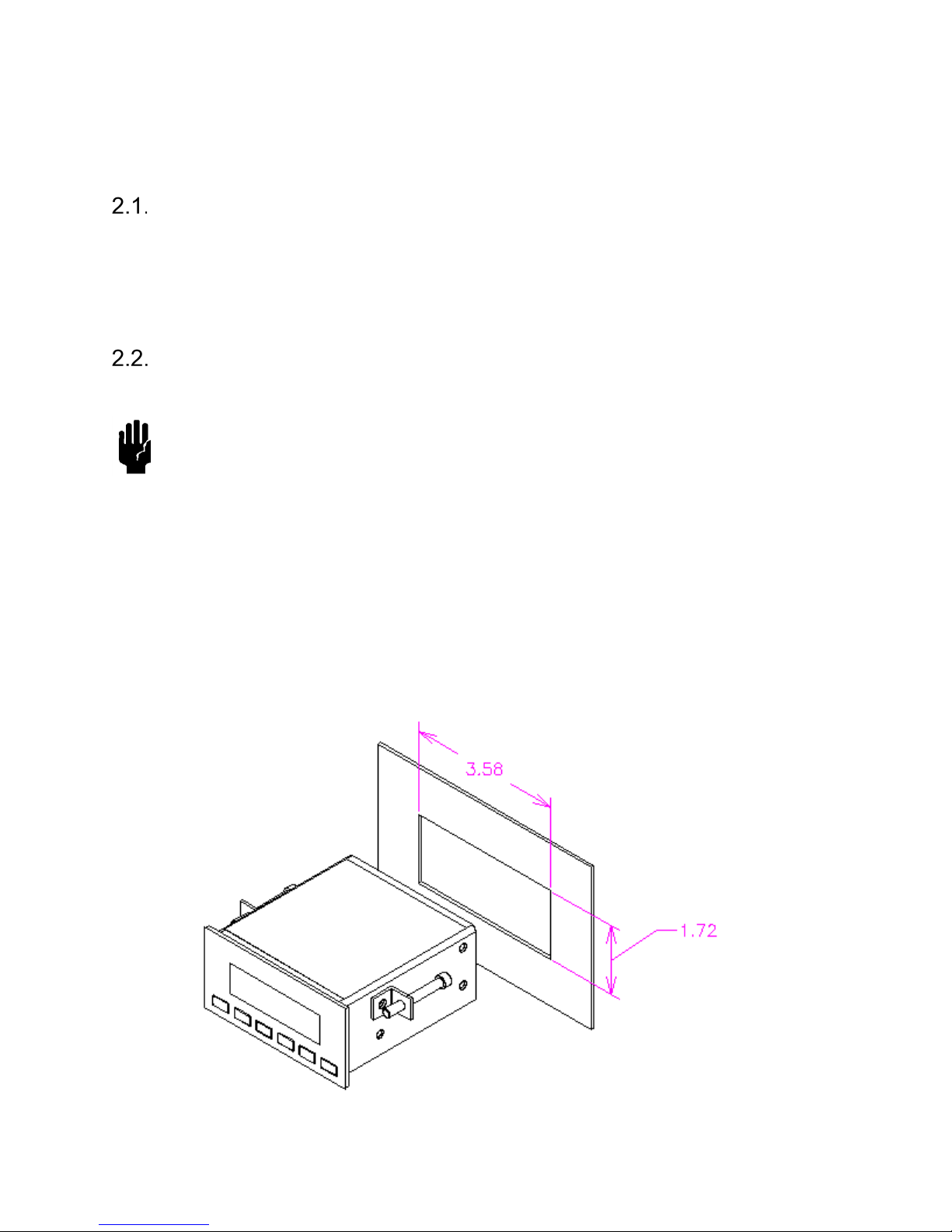
The THCD-100 can be panel mounted, or used on a bench top and is a standard 96 x 48mm panel meter
enclosure. Note that the instrument must always be situated in such a way as to enable adequate air
circulation about the unit. If a transducer was supplied with the THCD-101, a suitable cable may have been
included.
A panel mount kit will have been supplied with the instrument. This consists of two screws (M3x6), two
brackets and two screws (50mm). Fit the M3x6 screws into the side of the unit into the diagonally opposed
holes. Do not tighten these screws, to allow the bracket to slide over the screw head. Thread locking adhesive
may be used but is not required, as these screws cannot rotate once the bracket is tightened. Insert the meter
into the panel. A cutout of 3.63” x 1.84” (92 x 45mm) is recommended. Slip the mounting bracket over the
screw head and tighten the 50mm screws. The unit should now be secure.
181-122018_THCD-101 Instruction Manual Page 8 of 26
 Loading...