


MANUAL ADDENDUM
MODEL T102
TOTAL REDUCED SULFU R ANALYZER
with
MODEL 501 TRS
THERMAL CONVERTER
(to be used in conjunction with T101 Operation Manual, PN 07266)
© TELEDYNE API (TAPI)
9970 Carroll Canyon Road
SAN DIEGO, CA 92131-1106
USA
Toll-free Phone:
800-324-5190
Phone:
+1 858-657-9800
Fax:
+1 858-657-9816
Email:
api-sales@teledyne.com
Website:
http://www.teledyne-api.com/
Copyright 2011-2012
07267B DCN6485
Teledyne API (TAPI)
11 June 2012


i
NOTICE OF COPYRIGHT
© 2011-2012 Teledyne API (TAPI). All rights reserved.
TRADEMARKS
All trademark s, regi ster ed trad emark s, bran d nam es or pr oduct names
appearing in t hi s docu ment ar e the p rop ert y of thei r resp ect i ve ow ne rs
and are used herein for identification purposes only.
07267B DCN6485

ii
This page intentionally left blank.
07267B DCN6485
iii
SAFETY MESSAGES
Important safety messages are provided throughout this manual for the purpose of
avoiding personal injury or instrument damage. Please read these messages
carefully. Each safety message is associated with a safety alert symbol, and are
placed throughout this manual; the safety symbols are also located inside the
instrument. It is imperative that you pay close attention to these messages, the
descriptions of which are as follows:
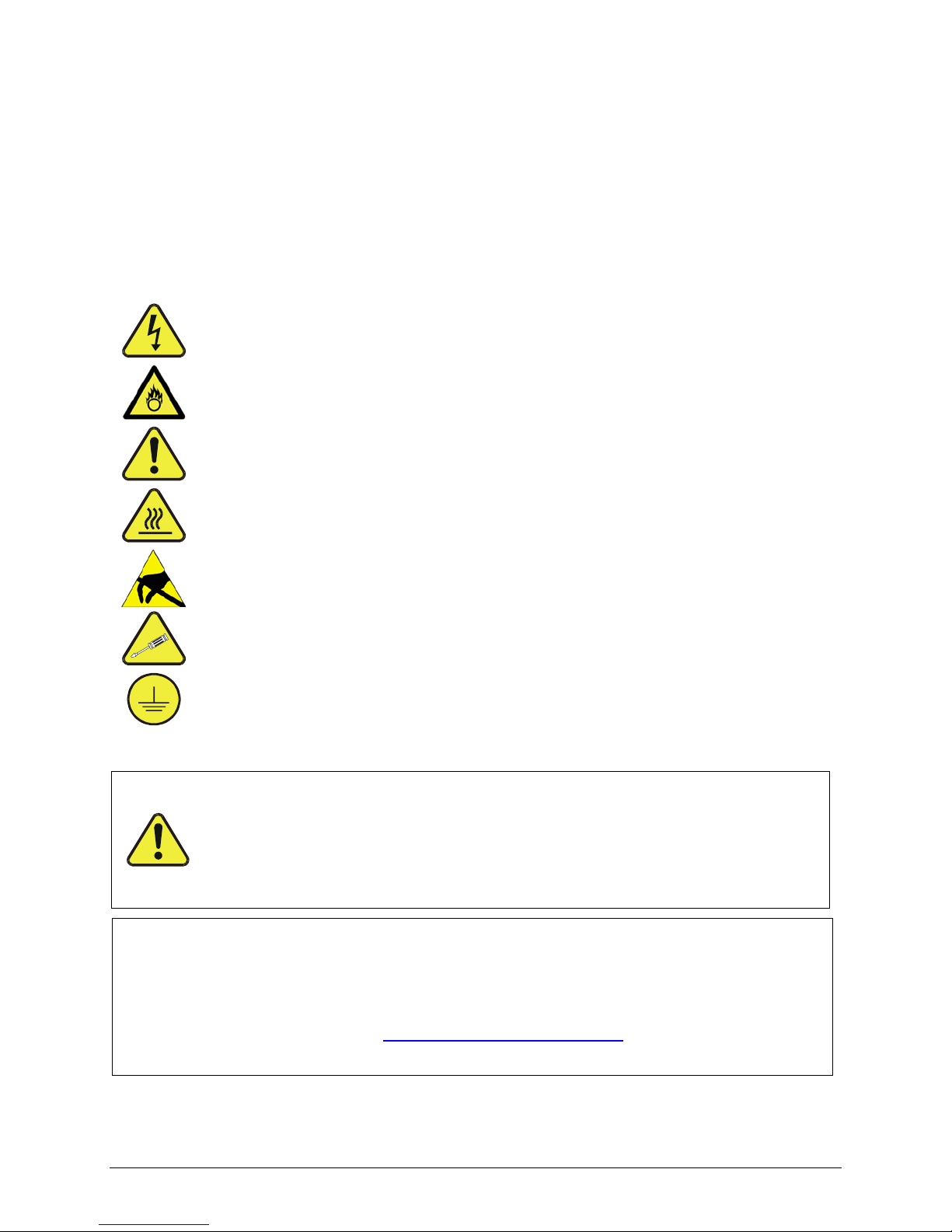
WARNING: El ect rical Shock Hazard
HAZARD: Strong oxidizer
GENERAL WAR NING/CAUTION: Read the accompanying message for
spec ific information.
CAUTION: Hot Surface Warning
Do Not Touch: Touching some parts of the instrument without protection or
proper tools could result in damage to the part(s) and/or the instrument.
Technician Symbol: All operations marked with this symbol are to be
performed by qualified maintenance personnel only.
Electrical Grou nd: This symbol inside the instrument marks the central
safety grounding point for the instrument.
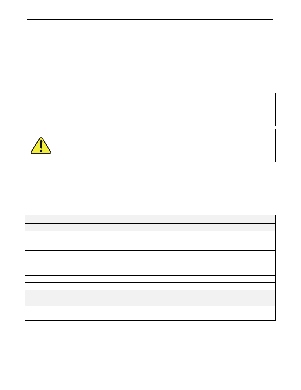
CAUTION
This instrument should only be used for the purpose
and in the
manner described in this manual. If you use this instrument
in a
manner other than that for which
it was intended, unpredictable
behavior could ensue with possible hazardous consequences.
NEVER use any gas analyzer to sample combustible gas(es)!
Note
For Technical Assistance regarding the use and maintenance of this instrument or any other
Teledyne API product, contact Teledyne API’s Technical Support Department:
Telephone: 800-324-5190
Email: sda_techsupport@teledyne.com
or access any of the service options on our website at http://www.teledyne-api.com/
07267B DCN6485
iv
CONSIGNES DE SÉCURITÉ
Des consignes de sécurité importantes sont fournies tout au long du
présent manuel dans le but d’éviter des blessures corporelles ou
d’endommager les instruments. Veuillez lire attentivement ces consignes.
Chaque consigne de sécurité est représentée par un pictogramme
d’alerte de sécurité; ces pictogrammes se retrouvent dans ce manuel et à
l’intérieur des instruments. Les symboles correspondent aux consignes
suivantes :
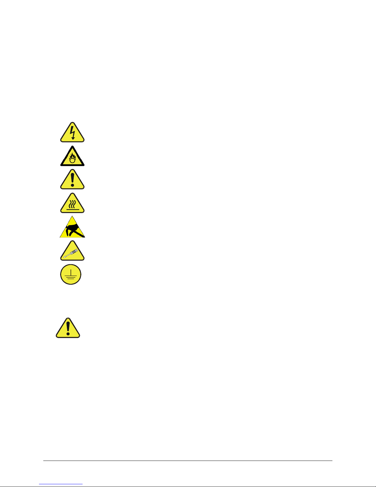
AVERTISSEMENT : Risque de choc électrique
DANGER : Oxydant puissant
AVERTISSEMENT GÉNÉRAL / MISE EN GARDE : Lire la consigne
complémentaire pour des renseignements spécifiques
MISE EN GARDE : Surface chaude
Ne pas toucher : Toucher à certaines parties de l’instrument sans protection ou
sans les outils appropriés pourrait entraîner des dommages aux pièces ou à
l’instrument.
Pictogramme « technicien » : Toutes les opérations portant ce symbole doivent
être effectuées uniquement par du personnel de maintenance qualifié.
Mise à la terre
: Ce symbole à l’intérieur de l’instrument détermine le point central
de la mise à la terre sécuritaire de l’instrument.
MISE EN GARDE
Cet instrument doit être utilisé aux fins décrites e t de la manière décrite dans
ce manuel. Si vous utilisez cet instrument d’une autre manière que celle pour
laquelle il a été prévu, l’instrument pourrait se comporter de façon imprévisible
et entraîner des conséquences dangereuses.
NE JAMAIS utiliser un analyseur de gaz pour échantillonner des gaz
combustibles!
07267B DCN6485
v
WARRANTY
WARRANTY POLICY (02024 F)
Teledyne API (TAPI), a business unit of Teledyne Instruments, Inc., provides that:
Prior to shipment, TAPI equipment is thoroughly inspected and tested. Should
equipment failure occur, TAPI assures its customers that prompt service and support
will be available.
COVERAGE
After the warranty period and throughout the equipment lifetime, TAPI stands ready
to provide on-site or in-plant service at reasonable rates similar to those of other
manufacturers in the industry. All maintenance and the first level of field
troubleshooting are to be performed by the customer.
NON-TAPI MANUFACTURED EQUIPMENT
Equipment provided but not manufactured by TAPI is warranted and will be repaired
to the extent and according to the current terms and conditions of the respective
equipment manufacturer’s warranty.
Product Return
All units or components returned to Teledyne API should be properly packed for
handling and returned freight prepaid to the nearest designated Service Center.
After the repair, the equipment will be returned, freight prepaid.
The complete Terms and Conditions of Sale can be reviewed at
http://www.teledyne-api.com/terms_and_conditions.asp
CAUTION – Avoid Warranty Invalidation
Failure to comp ly wi th proper ant i-Electro-
Static Discharge (ESD) handling and packing
instructions and Retu
rn Merchandise Authorization (RMA) procedures when returning
parts for repair or calibration may void your warranty. For anti-
ESD handling and
packing i nstructions pl ease refer to “Pack ing Componen ts for Return t o Teledyne AP I’s
Customer Ser v ice” in the Primer on Electro-Static Discharge section of this manual, and
for RMA pro cedures pl ease ref er to our W ebsite at
http://www.teledyne-api.com under
Customer Support > Return Authorization.
07267B DCN6485

vi
This page intentiona lly left blank.
07267B DCN6485

vii
ABOUT THIS MANUAL
This T102 Addendum, PN 07267, is comprised of multiple documents as follows.
Part
No.
Rev
Name/Description
07267 B T102 Addendum
05515 B T102 Menu Trees (inserted as Appendix A in this addendum)
07349 1/7/11 Spare Parts List (located in Appendix B of this addendum)
05517 C Repair Questionnaire (inserted as Appendix C in this addendum)
03404 L Assembly Diagram, M501TS Converter
05764
A Wiring Diagram, M501TS (034040100) (located in Appendix D of this
addendum)
NOTE
Please read this manual in its entirety before making any attempt made to ope r a te the in s tru me nt.
REVISION HISTORY
T102/501 TRS Addendum, PN07267
Date
Rev
DCN
Change Summary
2012 June 11
B
6485
Administrative updates
2011 February 4
A
5975
Initial Release
07267B DCN6485

viii
This page intentionally left blank.
07267B DCN6485

ix
TABLE OF CONTENTS
1. INTRODUCTION ..........................................................................................................................13
1.1. Reference Number in g Con vention .............................................................................................. 14
2. SPECIFICATIONS AND APPR O VAL S.............................................................................................15
2.1. Specifications .......................................................................................................................... 15
2.1.1. M501-TRS Specification s .................................................................................................... 15
2.2. EPA Equivalency Des ign a tion .................................................................................................... 15
2.3. CE Mark Compliance ................................................................................................................ 16
3. GETTING STARTED ......................................................................................................................17
3.1. Unpacking the T102 ................................................................................................................. 17
3.2. Unpacking the M501-TRS ......................................................................................................... 17
3.2.1. M501-TRS Ventilation Clear ance ......................................................................................... 17
3.3. Interna l L a youts ...................................................................................................................... 19
3.4. T102 and M501-TRS Internal Pneumatic Flow ............................................................................. 20
3.5. Rear Panel Layou t f or the T102 & M 501-TRS ............................................................................... 22
3.6. Initial Setup ............................................................................................................................ 23
3.6.1. Electrica l Connections ........................................................................................................ 23
3.6.1.1. T102 Analog Output Connections .................................................................................. 23
3.6.1.2. M501-TRS A la rm Output Connec tions ............................................................................ 24
4. PNEUMATIC CONNECTIONS ........................................................................................................25
4.1.1.1. Connections with Inte r nal Valve Options Installed ........................................................... 28
4.2. Initial Operation ...................................................................................................................... 30
4.2.1. Startup / Warm U p of the T 102 .......................................................................................... 30
4.2.2. Functional Check of the T102 ............................................................................................. 30
4.2.3. Startup / Warm U p of the M 501-TRS ................................................................................... 31
4.3. Initial Ca libr ation ..................................................................................................................... 32
5. OPTIONAL HARDWARE AND SOFTWARE .....................................................................................33
5.1. Rack Mount Kits (Opti on s 20a , 20b, 21, 22 & 81) ........................................................................ 33
5.2. Calibration Valves Options ........................................................................................................ 33
5.2.1. Zero/Span Va lv es (Opti on 50) & Internal Zero/Spa n Gas Generator (Option 51) ....................... 33
6. T102 OPERATING INSTRUCTIONS ..............................................................................................37
6.1.1. T102 Analog Output S ignals ............................................................................................... 37
6.1.2. Setting the T102 Ga s M ea s urement Mode ............................................................................ 38
6.2. SETUP – DIAG: Using the Diagnostics Functions .......................................................................... 38
6.2.1. T102 Analog I/O Configuration ........................................................................................... 38
6.2.2. T102 Test Channel O utput ................................................................................................. 39
6.3. SETUP – COMM: Setting Up the T102’s Communication P orts ........................................................ 39
6.3.1. T102 ID Code ................................................................................................................... 39
6.3.2. T102 Ethernet Host N a me .................................................................................................. 39
6.4. Remote Operation of the Analyzer ............................................................................................. 40
6.4.1. Control I nputs .................................................................................................................. 40
6.4.2. Using th e T102 with a Hessen P r otocol Network .................................................................... 41
6.4.2.1. T102 Hessen Protocol Gas ID List. ................................................................................ 41
6.4.2.2. Setting Hessen Protocol Status Flags ............................................................................ 42
7. M501-TRS OPERATING INSTRUCTIONS ......................................................................................43
7.1. Basic M501-TRS Controls .......................................................................................................... 43
7.2. To Display The Current Temper a ture .......................................................................................... 45
7.3. To Manually Adju s t the Converter Oven Temperatur e ................................................................... 45
7.4. Autotune the Tempera ture Controller ......................................................................................... 46
7.4.1. Initiating the Autotune Process ........................................................................................... 46
7.4.2. Aborting the Autotune Process ............................................................................................ 47
7.5. M501TRS Alarm Relay A djustment ............................................................................................. 47
8. CALIBRATION PROCEDURES .......................................................................................................49
8.1. T102 Calibration ...................................................................................................................... 49
8.2. M501-TRS Calibr a tion .............................................................................................................. 49
9.1. Additional and Update d M a intenance Procedures ......................................................................... 53
9.1.1. Maintaining the SO2 Scrubber ............................................................................................. 53
9.1.1.1. Predicting When to Replace the SO2 Scrubber ................................................................ 53
9.1.1.2. Checking the Function of the SO2 Scrubber .................................................................... 54
07267B DCN6485

TABLE OF CONTENTS Teledyne API - T102/501 TRS, Addendum to T101 Operation Manual
x
9.1.1.3. Changing the SO2 Scrubber Material ............................................................................. 54
10. THEORY OF OPERATION ............................................................................................................55
10.1. Measurement Principle ........................................................................................................... 55
10.1.1. TRS Conversion .............................................................................................................. 55
10.1.2. SO2 Ultraviolet Fluorescence ............................................................................................. 56
10.2. The UV Light Path .................................................................................................................. 58
10.2.1. UV Lamp Shutter & PMT O ff s et ......................................................................................... 58
10.3. Pneumatic Operation .............................................................................................................. 59
10.3.1. Sample gas Flow ............................................................................................................. 59
10.3.2. M501 SO2 Scrubber ......................................................................................................... 59
10.4. Electronic O p eration ............................................................................................................... 60
10.4.1. Sensor Module ................................................................................................................ 60
10.4.1.1. Sample Cham ber ...................................................................................................... 61
10.4.1.2. Sample Cham ber Heating Circuit ................................................................................ 61
10.4.2. M501-TRS Elec tronics ...................................................................................................... 62
10.4.2.1. Thermal Sw itch ........................................................................................................ 62
10.4.2.2. Temperature A larms and Alarm Output ....................................................................... 63
11. TROUBLESHOOTING AND REPAIR .............................................................................................65
11.1.1. Fault Diagnosis with Warning Messages ............................................................................. 65
11.1.1.1. T102 Warning Mess a ges ............................................................................................ 65
11.1.1.2. M501-TRS Error Codes .............................................................................................. 65
11.1.2. Fault Diagnosis with Test Functions ................................................................................... 66
11.2. M501-TRS Trou b les hooting ..................................................................................................... 67
11.2.1. TRS Converter Not Heating: ............................................................................................. 67
11.3. Other Performance Problems ................................................................................................... 68
11.3.1. Excessive n oise ............................................................................................................... 68
11.4. Subsystem Checkout .............................................................................................................. 68
11.4.1. Checking th e Ef f ic iency of the M501-TRS SO2 Scrubber ........................................................ 68
11.4.2. Checking th e Ef f ic iency of the M501-TRS TRS SO2 Converter ............................................ 68
11.5. Additional Repair Pro c edures ................................................................................................... 70
11.5.1. UV Lamp Adjustment and/or Replacement .......................................................................... 71
11.5.1.1. Adjusting the UV Lamp (Peaking the Lamp) ................................................................. 71
11.5.1.2. Replacing the UV La m p.............................................................................................. 72
11.5.2. Repla cing the U V Filter/ Lens .............................................................................................. 73
11.5.3. Replacing the PMT , HVPS or TEC ....................................................................................... 74
11.5.4. T102 PMT Hardw a re Ca libra tion (FACTORY CAL).................................................................. 77
11.5.5. Replacing the TRS C onverter Heating Tube ......................................................................... 80
11.5.6. Replacing the Ther m ocouple ............................................................................................. 81
11.6. Manually Progra m m in g the M501-TRS Temperature C ontroller .................................................... 84
11.6.1. Temperature Controller Primary Menu P a r a m eters ............................................................... 85
11.7. Technical Assistance .............................................................................................................. 87
LIST OF APPENDICES
APPENDIX A - VERSION SPECIFIC SOFTWARE DOCUMENTATION
APPENDIX A-1: T102 Software Menu Trees, Revision A.2
APPENDIX A-2: Setup Variables For Serial I/O, Revision A.2
APPENDIX A-3: Warnings and Test Functions, Revision A.2
APPENDIX A-4: T102 Signal I/O Definitions, Revision A.2
APPENDIX A-5: T102 iDAS Functions, Revision A.2
APPENDIX B - T102 SPARE PARTS LIST
APPENDIX C - T102 REPAIR REQUEST FORM
APPENDIX D - ELECTRONIC SCHEMATICS
07267B DCN6485

Teledyne API - T102/501 TRS, Addendum to T101 Operation Manual TABLE OF CONTENTS
xi
LIST OF FIGURES
Figure 3-1. T102 Internal Layout .......................................................................................... 19
Figure 3-2. M501-TRS Internal Layout .................................................................................. 20
Figure 3-3. Internal Pneumatic Diagram of the T102 Standard Configuration ............................. 21
Figure 3-4. T102 Rear Panel (with Zero Air Scrubber attached) ................................................ 22
Figure 3-5. M501-TRS Rear Panel Layout ............................................................................... 22
Figure 3-6. Analog Output Connector .................................................................................... 23
Figure 4-1. Pneumatic Connections–Basic Configuration–Using Gas Dilution Calibrator ................ 26
Figure 4-2. Pneumatic Connections–Basic Configuration–Using Bottled Span Gas ....................... 26
Figure 4-3. Basic Pneumatic Connections for Units with Zero/Span Valve Option ........................ 28
Figure 4-4. Pneumatic Connections for Formal Calibration of Units w/ IZS Valve Option .............. 29
Figure 4-5. Pneumatic Connections for Informal Calibration Checks of Units with IZS Valve Op t io n 29
Figure 4-6. M501-TRS Temperature Controller Startup ............................................................ 31
Figure 5-1. Internal Pneumatic Diagram of the T102 With Z/S Option Installed .......................... 34
Figure 5-2. Internal Pneumatic Diagram of the T102 with IZS Options Installed ......................... 35
Figure 6-1. Analog Output Connector .................................................................................... 37
Figure 6-2. Control Inputs with Local 5 V Power Supply ........................................................... 40
Figure 6-3. Control Inputs with External 5 V Power Supply ...................................................... 41
Figure 7-1. M501-TRS Temperature Controls ......................................................................... 43
Figure 10-1. UV Absorption in the T102 Reaction Cell .............................................................. 56
Figure 10-2. T102 Sensor Module ......................................................................................... 60
Figure 10-3. T102 Sample Chamber ..................................................................................... 61
Figure 10-4. M501-TRS Electronic Block Diagram ................................................................... 62
Figure 11-1. Shutter Assembly - Exploded View ..................................................................... 72
Figure 11-2. Disassembling the Shutter Assembly .................................................................. 73
Figure 11-3. PMT Assemb ly - Exploded View .......................................................................... 74
Figure 11-4. Pre-Amplifier Board Layout ................................................................................ 78
Figure 11-5. The rmo couple .................................................................................................. 82
Figure 11-6. C av ity for Thermocouple ................................................................................... 82
Figure 11-7. Thermocouple Installed ..................................................................................... 83
Figure 11-8. Ti e-W rap H old-Down Location ............................................................................ 83
LIST OF TABLES
Table 2-1: Model 501 Basic Unit Specifications ....................................................................... 15
Table 3-1. TRS – SO2 Switching Valve Operating Modes .......................................................... 21
Table 3-2. Analog output Pin Outs ........................................................................................ 23
Table 4-1. Table 3-3: Inlet / Outlet Connector Labels and Functions ..................................... 25
Table 4-2. NIST-SRM's Available for Traceability of H2S & SO2 Calibration Gases ....................... 28
Table 5-1. Zero/Span Valve Operating States......................................................................... 34
Table 5-2. IZS Valve Operating States .................................................................................. 35
Table 6-1. T102 Gas Measurement Modes ............................................................................. 38
Table 6-2. Analog Output Pin Assignments ............................................................................ 38
Table 6-3. Test Parameters Av ailable for Analog Output A4...................................................... 39
Table 6-4. T102 Control Input Pin Assignments ...................................................................... 40
Table 6-5. T102 Default Hessen Gas ID’s ............................................................................... 41
Table 6-6. Default Hessen Status Bit Assignments .................................................................. 42
Table 7-1. M501-TRS Temperature Controls and Definitions ..................................................... 44
Table 8-1. T102 Preventive Maintenance Schedule .................................................................. 51
Table 11-1. Test Functions - Possible Causes for Out-Of-Range Values ...................................... 66
Table 11-2. Test Functions - Possible Causes for Out-Of-Range Values ...................................... 66
Table 11-3. Temperature Controller – Primary Parameter Settings ............................................ 86
Table 11-4. Temperature Controller – Secondary Parameter Settings ........................................ 87
07267B DCN6485

TABLE OF CONTENTS Teledyne API - T102/501 TRS, Addendum to T101 Operation Manual
xii
This page intentionally left blank.
07267B DCN6485

13
1. INTRODUCTION
NOTE
The information contained in this addendum is pertinent to T102 analyzers running
software revision G.4. Some or all of the information may not be applicable to
previous revision of that software.
This addendum is based on the Model T101 Operators Manual (PN 07266). In most
ways the T102 is identical to the T101 in design and operation; therefore most of the
basic set up information, operating instructions as well as calibration, maintenance,
troubleshooting and repair methods are found in that manual.
This addendum documents only those areas where the T102 is different in design or
operating method from the T101.
Specifically:
• Areas where updates and improvements to the Model T10X software
have been implemented since the publication date of the T101 Manual PN 07266.
• EXTERNAL TRS CONVERSION: Like the T101, which converts H
2
S to
SO
2,
then measures the amount of SO2 present using a UV fluorescence
technique, the T102 converts total reduced sulfur (TRS) gases into SO
2
before measuring the SO
2
using the same UV fluorescence method.
Unlike the T101, which performs the H2S SO2 conversion internally, the T102
requires an external TRS converter, in this case a TAPI M501-TRS.
Therefore this addendum includes instructions and information regarding:
• Are as of operation and setup of the T102 that depart from the
method described by the T101 operator’s manual due to the TRS
SO2 conversion being performed externally.
• The proper setup and operation on the M501-TRS.
07267B DCN6485

INTRODUCTION Teledyne API - T102/501 TRS, Addendum to T101 Operation Manual
14
1.1. Reference Numbering Convention
Unless otherwise specified, chapter, section, figure and table reference numbers referred
to within this text are relative to this document.
EXAMPLE: “Figure 2-1” refers to the figure, within this document, labeled
as 2-1.
References to chapters, sections, figures and tables in the original document will be
labeled as such.
EXAMPLE: “Front Panel Display Figure in Overview of Operating modes
section of the T101 Operators Manual (PN 07266)”.
07267B DCN6485

15
2. SPECIFICATIONS AND APPROVALS
2.1. Specifications
As there are no significant differences between the performance specifications for the
T102 an d the T101 please refer to in the Specification section of th e T101 Manual - PN
07266. However, the AC power specifications for the T102 are as follows:
T102 AC Power: 100V – 120V, 60Hz (200W); 220V – 240V, 50Hz (211W)
2.1.1. M501-TRS Specifications
Table 2-1: Model 501 Basic Unit Specifications
Minimum Converter Efficiency
H
2
S >95%
COS >90%
CS
2
>90%
Maximum TS Concentration for
specified conversion efficiency
20 ppmv
Sample Flow Rate 650cc/min. ±10% - driven by T102 pneum atic sys te m
Optimum Converter
Temperature
850°C (factory setup)
Maximum Converter
Temperature
1100°C
Dimensions H x W x D 7" x 17" x 23.5" (178 mm x 432 mm x 597 mm)
Weight
16 lbs (7.3 kg)
26 lbs (11.8 kg ) CE version
AC Power Rating
115 V, 50/60 Hz - 400 Watts;
230 V, 50/60 Hz - 575 Watts; CE Version
Internal Alarms
High Alarm Point: 900°C
Low Alarm Point: 800°C
Alarm Output Relay
SPST - 1 point: Alarm output is energized should either the temperature
controller’s high or low internal alarm set points be activ ate d.
Alarm Output Rating
220V AC/30V DC, 1A (resistive load)
Environmental Installation category (over-volta g e c ateg or y ) II ; Pollutio n d eg r ee 2
Certifications
IEC 1010-1 / 61010-1:93 (includes A1) + A2:95,
For indoor use at altitudes ≤ 2000m only
2.2. EPA Equivalency Designation
No EPA equivalency standards exist for TRS measurement, however, the T102 analyzer
qualifies for EPA equivalency designation as Reference Method Number EQSA-0495100 per 40 CFR Part 53 when operated under the following conditions:
• Measurement Mode: SO2 single gas mode.
07267B DCN6485

SPECIFICATIONS AND APPROVALS Teledyne API - T102/501 TRS, Addendum to T101 Operation Manual
16
• Range: Any range from 50 parts per billion (ppb) to 10 parts per million
(ppm).
• Ambient temperature range of 5
o
C to 40 oC.
• Line voltage range of 105-125 VAC or 220-240 VAC, at 50 or 60 Hz.
• Sample filter: Equipped with PTFE filter element in the internal filter
assembly.
• Sample flow of 650 +/- 65 cc/min.
• Vacuum pump (internal or external) capable of 14"Hg Absolute pressure
@ 1 slpm or better.
• Software settings:
Dynamic span
OFF
Dynamic zero
OFF
Dilution factor
OFF
AutoCal
ON or OFF
Dual range
ON or OFF
Auto-range
ON or OFF
Temp/Pressu r e com pensation
ON
Under the designation, the analyzer may be operated with or without the following
optional equipment:
• Rack mount with chassis slides.
• Rack mount without slides, ears only.
• Zero/span valve options.
• Inter nal zero/span (IZS) option with either:
• SO2 permeation tube - 0.4 ppm at 0.7 liter per minute;
certified/uncertified.
• SO2 permeation tube - 0.8 ppm at 0.7 liter per minute;
certified/uncertified. Under the designat ion, the IZS option cannot be
used as the sourc e of calibration.
• 4-20mA isolated ana log outputs.
• Status outputs.
• Control inputs.
• RS-232 output.
• Ethernet output.
• Zero air scrubber.
• 4-20mA, isolated o utput.
2.3. CE Mark Compliance
See Section titled CE Mark Compliance in the T101 Manual - PN 07266
07267B DCN6485
17
3. GETTING STARTED
3.1. Unpacking the T102
Unpack the T102 as per the directions in section titled Unpacking and Initial Setup in
the T101 Manual - PN 07266.
There are no shipping screws to be removed in the T102.
3.2. Unpacking the M501-TRS
There are no shipping screws to be removed in the M501-TRS.
1. Inspect the shipping package for external damage. If damaged, please
advise the shipper first, then Teledyne API (TAPI).
2. Carefully remove the top cover of the converter and check for internal
shipping damage.
a. Remove the screws fastening the top cover to the unit (four per
side).
b. Lift the cover straight up.
WARNING
Never disconnect electronic circuit boards, wiring harnesses or
electronic sub assemblies while the unit is under power.
3. Inspect the interior of the instrument to make sure all components are in
good shape and properly seated.
4. Check the connectors of the various internal wiring harnesses and
pneumatic hoses to make sure they are firmly and properly seated.
5. Replace the top cover and fasten with original screws.
NOTE
The M501-TRS will not operate properly with the top cover removed.
The air cooling required to stabilize the temperature of the converter tube is
dependen t on air flow patterns that only exist with the top cover in place.
Without the top cover in place, the thermal cutout may overheat and shut off the
heating element.
3.2.1. M501-TRS Ventilation Clearanc e
Whether the M501-TRS is set up on a bench or installed into an instrument rack, be sure
to leave sufficient ventilation clearance.
07267B DCN6485

GETTING STARTED Teledyne API - T102/501 TRS, Addendum to T101 Operation Manual
18
AREA MINIMUM REQUIRED CLEARANCE
Behind the instrument 10 cm / 4 inches
Sides of the instrument 2.5 cm / 1 inch
Above and below the instrument. 2.5 cm / 1 inch
NOTE
If the M501-TRS is installed in an instrument rack or any type of enclosure, make
sure that the rack/enclosure itself is ad equately ventilat ed.
Failure to provide proper ven tilation ca n result in the ambient temperat ure exceeding
the maximum operating temperature s pecification for the T102 (40°C)
07267B DCN6485
Teledyne API - T102/501 TRS, Addendum to T101 Operation Manual GETTING STARTED
19
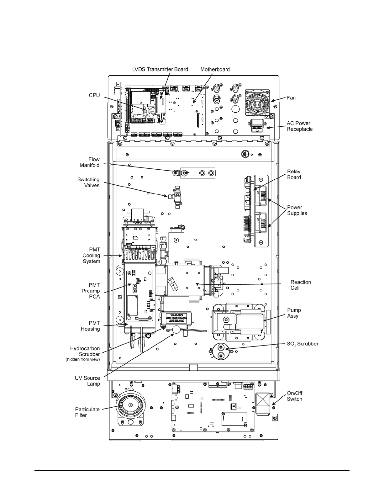
3.3. Internal Layouts
Figure 3-1 supersedes the T101 internal chassis layo ut i n the T101 Manual - PN 07266.
Figure 3-1. T102 Internal Layo ut
07267B DCN6485
GETTING STARTED Teledyne API - T102/501 TRS, Addendum to T101 Operation Manual
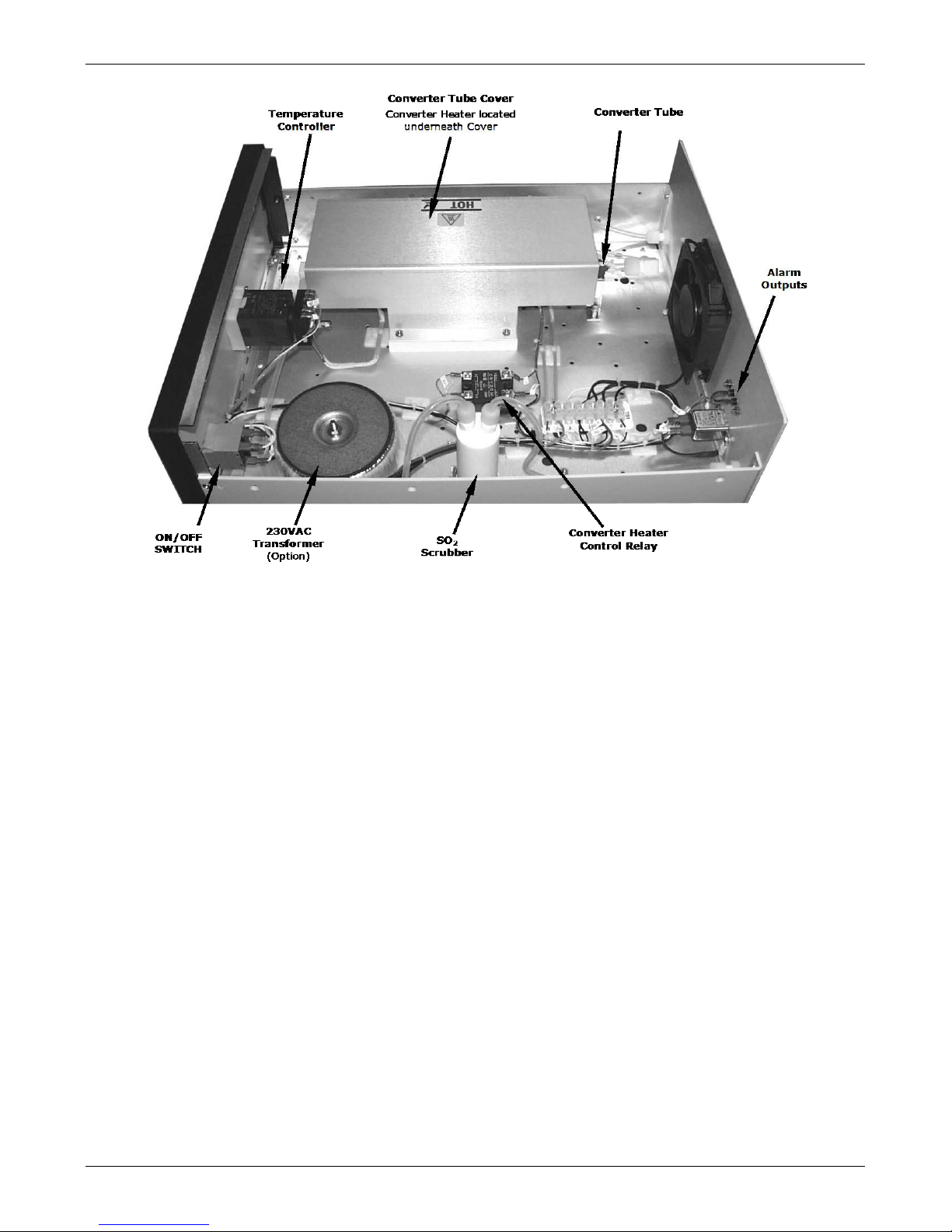
20
Figure 3-2. M501-TRS Internal Layout
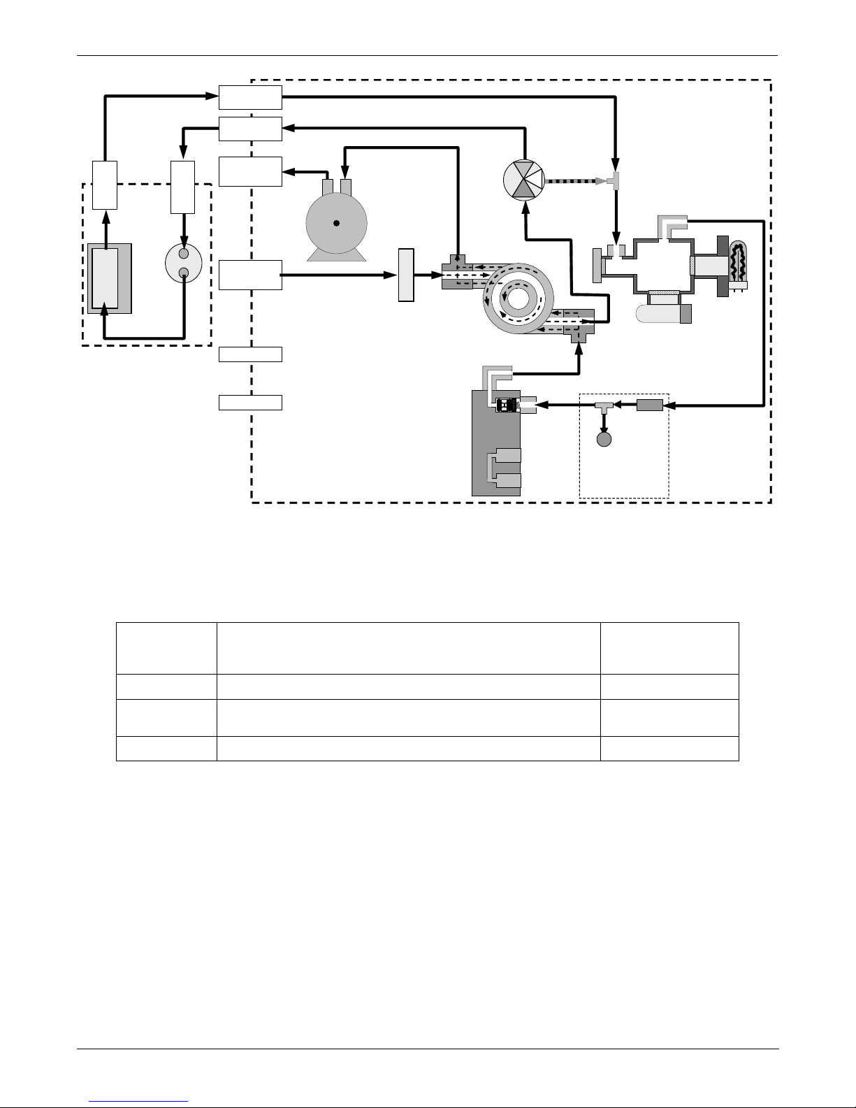
3.4. T102 and M501-TRS Internal Pneumatic Flow
Figure 3-3 shows the internal pneumatic flow of the T102 in its Standard configuration.
For information on instruments with the various zero/span valve options refer to Section
5.2, Figure 5-1 and Figure 5-2.
07267B DCN6485
Teledyne API - T102/501 TRS, Addendum to T101 Operation Manual GETTING STARTED
21
COM
NO
NO
SAMPLE GAS
INLET
SPAN GAS INLET
ZERO AIR INLET
VACUUM MANIFOLD
FLOW
CONTROL
ASSY
EXHAUST TO OUTER
LAYER OF KICKER
SAMPLE FILTER
INSTRUMENT
CHASSIS
EXHAUST GAS
OUTLET
KICKER EXHAUST
TO PUMP
HYDROCARBON
SCRUBBER
(KICKER)
UV
LAMP
PMT
SAMPLE
CHAMBER
FLOW
SENSOR
FLOW / PRESSURE
SENSOR PCA
SAMPLE
PRESSURE
SENSOR
PUMP
TRS / SO2
MODE
VALVE
Gas Flow in SO2 phase
of multigas mode or
when in SO2
measurement mode
TO
CONVERTER
FROM
CONVERTER
M501-TRS
SO
2
Scrubbe
r
CONVERTER OVEN
TRS SO
2
TO
ANALYZER
FROM
ANALYZER
Figure 3-3. Internal Pneumatic Diagram of the T102 Standard Configuration
Table 3-1. TRS – SO
2
Switching Valve Operating Modes
GAS
MODE
CONDITION OF TRS –SO2 SWITCHING VALVE VALVE PORT
CONNECTION
(FIG. 5-2)
TRS
Open to SO
2
Scrubber and Molybdenum Converter
COM NO
SO2
Open to directly to Sample Chamber.
Bypasses M501-TRS
COM NC
TRS –SO2
Switches between above two states every 10 minutes.
- -
07267B DCN6485
GETTING STARTED Teledyne API - T102/501 TRS, Addendum to T101 Operation Manual
22
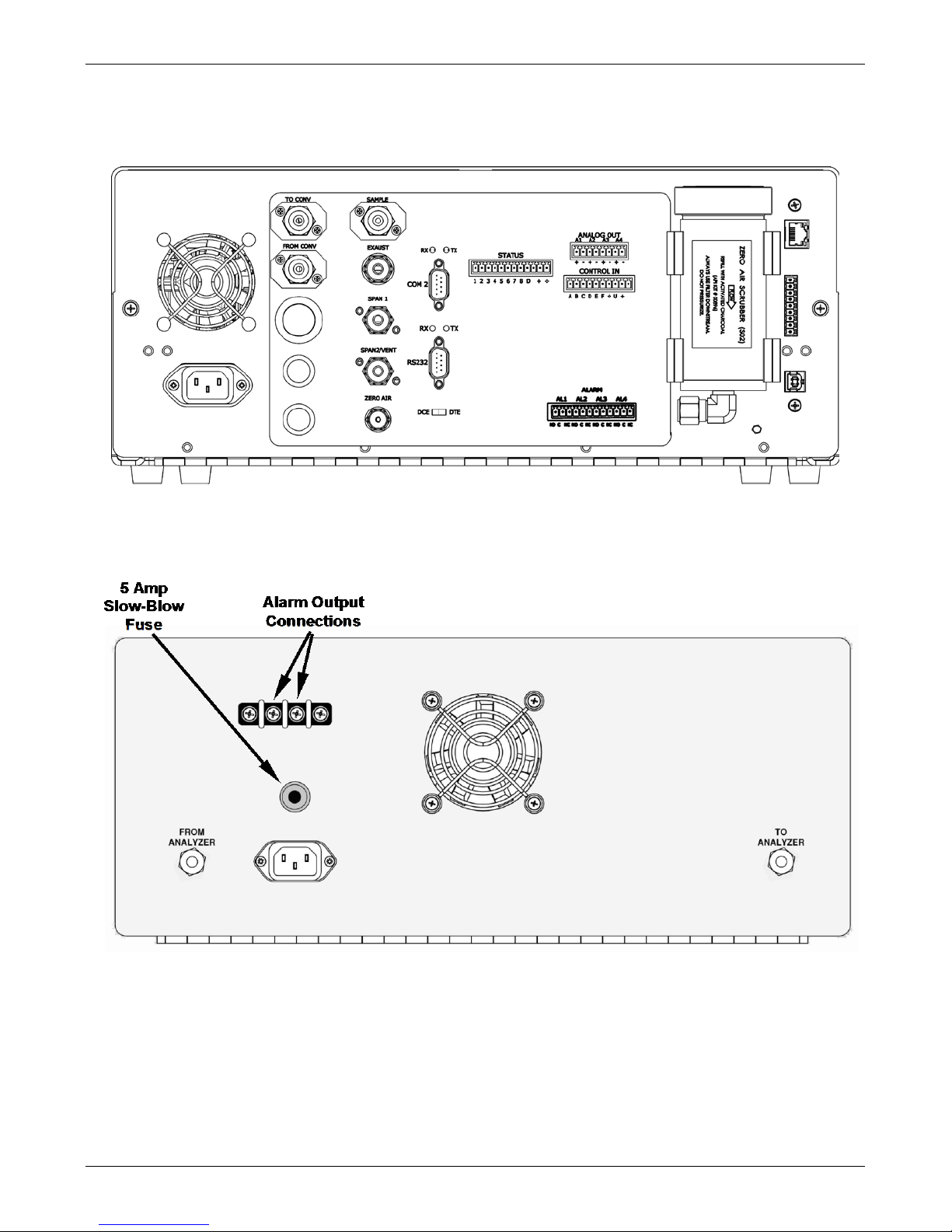
3.5. Rear Panel Layout for the T102 & M501-TRS
Figure 3-4 and Figure 3-5 supersede Rear Panel Layout in the T101 Manual - PN 07266.
Figure 3-4. T102 Rear Panel (with Zero Air Scru bber attached)
Figure 3-5. M501-TRS Rear Panel Layout
07267B DCN6485
Teledyne API - T102/501 TRS, Addendum to T101 Operation Manual GETTING STARTED
23
3.6. Initial Setup
3.6.1. Electrical Connections
The electrical connections for the T102 are the same as those described in the Electrical
Connections Section of t he T101 Manual - PN 07266 except for the test channel analog
output.
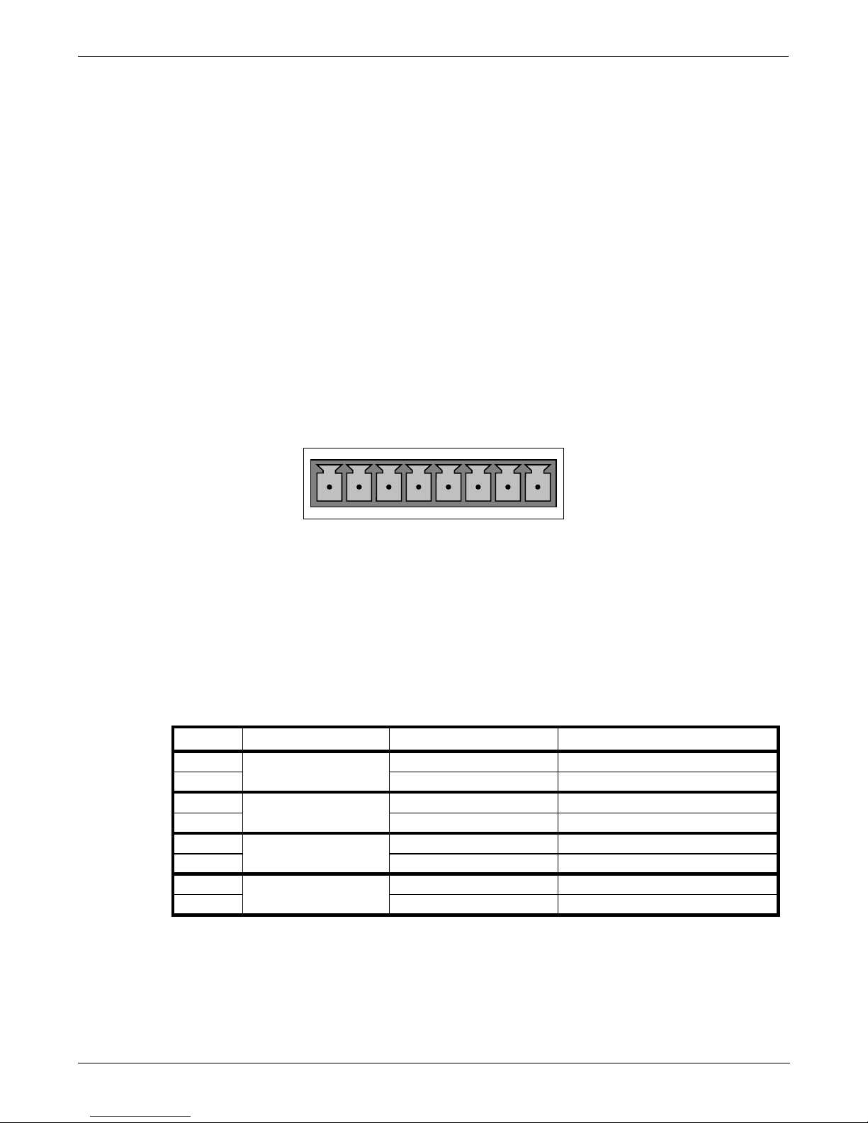
3.6.1.1. T102 Analog Output Connections
This section supersedes the Analog Output Connections section in the T101 Manual PN 07266.
Attach a strip chart recorder and/or data-logger t o the appropriate contacts of the analog
output connecter on the rear panel of the analyzer.
ANALOG OUT
A1 A2 A3 A4
+ - + - + - + -
Figure 3-6. Analog Output Connector
The A1 and A2 channels output a signal that is proportional to the SO2 concentration of
the sample gas.
The output, labeled A3 is special. It can be set by the user (see Test Channel Output
section in the T101 Manual - PN 07266) to output any one of the parameters accessible
through the <TST TST> keys of the units sample display.
Pin-outs for the Analog Output connector at the rear panel of the instrument are:
Table 3-2. Analog output Pin Outs
PIN ANALOG OUTPUT VOLTAGE OUTPUT CURRENT LOOP OPTION
1
A1
V Out
I Out +
2
Ground
I Out -
3
A2
V Out
I Out +
4
Ground
I Out -
5
A3
V Out
I Out +
6
Ground
I Out -
7
A4
Not Available
Not Available
8
Not Available
Not Available
• The defa ult analog output voltage setting of the T102 UV Fluorescence
SO
2
Analyzer is 0 – 5 VDC with a range of 0 – 500 ppb.
• To change these settings, see Analog I/O Configuration and SETUP –
RNGE: Analog Output Reporting Range Configuration sections,
respectively, in the T101 Manual - PN 07266.
07267B DCN6485

GETTING STARTED Teledyne API - T102/501 TRS, Addendum to T101 Operation Manual
24
3.6.1.2. M501-TRS Alarm Output Connections
The rear panel of the M501-TRS includes a terminal strip by which connections can be
made to the converter’s internal temperature alarm. For information on adjusting this
alarm see Section 7.5).
• Connect the input leads of your alarm-sensing device (e.g. datalogger)
to the center two pins of the alarm output connector (see).
• Make sure the load does not exceed the rated capacity of the relay.
07267B DCN6485
Teledyne API - T102/501 TRS, Addendum to T101 Operation Manual Pneumatic Connections
25
4. PNEUMATIC CONNECTIONS
This section supersedes the information contained in the Pneumatic Connections section
in the T101 Manual - PN 07266.
NOTE
To prevent dust from getting into the analyzer, it was shipped with small plugs
inserted into each of the pneumatic fittings on the rear panel. Make sure that all dust
plugs are removed before attaching exhaust and supply gas lines.
CAUTION
Sample and calibration gases should only come into contact with PTFE
(Teflon) or glass materials. They should not come in co nta ct with FEP or
stainless steel materials.
Figure 4-1 and Figure 4-2 show the most common configurations for gas supply and
exhaust lines to the Model T102 Analyzer. Figure 4-3, Figure 4-4, and Figure 4-5 show
the connections for units with valve options installed.
Please refer to Figure 3-4 and Figure 3-5 for the location of pneumatic connections at the
rear panel of the T102 and the M501-TRS instruments.
Table 4-1. Table 3-3: Inlet / Outlet Connector Labels and Functions
T102 PNEMATIC CONNECTERS
REAR PANEL LABEL
FUNCTION
SAMPLE
Connects the sample gas to the analyzer. When operating the analyzer without zero/span
option, this is also the inlet for any calibration gases.
EXHAUST
Exhausts the gas sampled by the analyzer. Connect to an outside area away from people.
SPAN
On units with zero/span/shutoff valve options installed, connect a gas line to the source of
calibrated span gas here.
ZERO AIR
On Units with zero/span valve or IZS option installed, this port connects the zero air gas or
the zero air cartridge to the analyzer.
TO CONVERTER
Sample gas leaves the T102 to be conditioned by the M501-TRS via this port.
FROM CONVERTER
Sample gas returns to the T102 after being conditioned by the M501-TRS via this port.
M501-TRS PNEUMATIC CONNECTERS
REAR PANEL LABEL
FUNCTION
FROM ANALYZER
Sample gas enters the M501-TRS from the T102 via this port.
TO ANALYZER
Sample gas leaves the M501-TRS to return to the T102 via this port.
07267B DCN6485
Pneumatic Connections Teledyne API - T102/501 TRS, Addendum to T101 Operation Manual
26
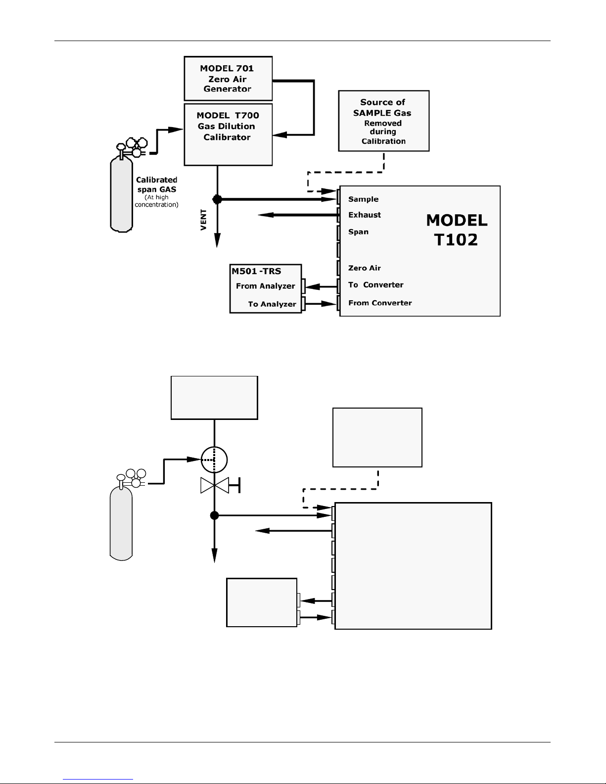
Figure 4-1. Pneumatic Connections–Basic Configuration–Using Gas D il ut ion Calibrator
VENT
Calibrated
Span GAS
Valve
Needle
valve to
control
flow
MODEL 701
Zero Air
Generator
Source of
SAMPLE Gas
Removed
during
Calibration
MODEL
T102
Sample
Zero Air
Exhaust
Span
To Converter
From Converter
M501-TRS
From Analyzer
To Analyzer
Figure 4-2. Pneumatic Connections–Basic Configuration–Using Bottled Span Gas
07267B DCN6485

Teledyne API - T102/501 TRS, Addendum to T101 Operation Manual Pneumatic Connections
27
1. Attach the 1/4" exhaust line to the exhaust port.
CAUTION
The exhaust from the instrument must be vented outside the immediate area or
shelter surrounding the instrument and conform to all safety requirements using
a maximum of 10 meters of 1/4” PTFE tubing.
2. Attach the sample line to the sample inlet port. Ideally, the pressure of
the sample gas should be equal to ambient atmospheric pressure.
NOTE
Maximum pressure of any gas at the sample inlet should not exceed 1.5 in-Hg above ambient
pressure and ideally should equal ambient atmospheric pressure.
In applications where the sample gas is received from a pressurized manifold, a vent must be
provided to equalize the sample gas with ambient atmospheric pressure before it enters the analyzer.
The vented gas needs to be routed outside the immediate area or shelter surrounding the instrument.
3. Attach zero air and span gas supply lines as appropriate (s ee Figure 3-4
and Figure 3-5).
Zero air and span gas inlets should supply their respective gases in excess of the 700
cc
3
/min demand of the analyzer. Supply and vent lines should be of sufficient length and
diameter to prevent back diffusion and pressure effects.
For this type of analyzer, zero air and span gas are defined as follows:
SPAN GAS
While it is possible to calibrate the T102 using SO2 as the span calibration gas by setting
the analyzer’s gas measurement mode to SO
2
, TAPI r ecommends that H2S be used and
that calibration operations be carried out with the analyzer’s TRS gas measurement
mode selected. Please note that verifying converter efficiency requires that the
instrument be calibrated on both TRS and SO
2
, and the slope factors compared between
the TRS and SO
2
modes.
It is recommended that the H
2
S span gas be equal to 90% of the analyzer’s selected
reporting range.
O2 is a quenching agent in fluorescent Sulfur analyzers. If the balance gas is pure
nitrogen, then false positive readings will result, both at zero and span. Therefore the
user should either use cylinders with zero air as the balance gas, or should use higher
concentration cylinders with an N
2
balance, and dilute further with zero air using a
calibrator, such as the TAPI M700.
EXAMPLE: If the selected reporting rang is 0 ppb 500 ppb, an appropriate span gas
concentration would be 450 ppb H
2
S.
Cylinders of calibrated H
2
S gas traceable to NIST-Standard Reference Material
specifications (also referred to as SRM’s or EPA protocol calibration gases) are
commercially available. Table 3-4 lists specific NIST-SRM reference numbers for various
concentrations of H
2
S.
07267B DCN6485
Pneumatic Connections Teledyne API - T102/501 TRS, Addendum to T101 Operation Manual
28
Table 4-2. NIST-SRM's Available for Traceability of H2S & SO2 Calibration Gases
NIST-SRM4 TYPE
NOMINAL
CONCENTRATION
2730
2731
Hydrogen sulfide in N
2
Hydrogen sulfide in N2
5000 ppb
20 ppm
ZERO AIR
Zero air is similar in chemical composition to the earth’s atmosphere but without the
gas(es) being measured by the analyzer, in this case total reduced sulfur (TRS). While
TRS typically includes Hydrogen sulfide (H
2
S), Dimethyl sulfide (CH3)2 , Dimethyl
disulfide (CH
3)2S2
and Methyl mercaptan (MeSH), CH4S many other gases fall into this
category as well. Other interferent gases may be present in ambient air as well.
To ensure that high quality zero air is available, a zero air generator such as the TAPI
Model 701 should be used.
If your analyzer is equipped with an IZS option, it is capable of creating zero air that is
adequate for performing informal calibration checks, but a zero air generator such as the
TAPI Model 701 is still recommended for performing formal calibration operations.
Once the appropriate pneumatic connections have been made, check all pneumatic
fittings for leaks using a procedure similar to that defined in the Detailed Pressu re Le ak
Check section in the T101 Manual - PN 07266.
4.1.1.1. Connections with Internal Valve Options Installed
If your analyzer is equipped with either the zero/span valve option (Option 50) or the
internal zero/span option (Option 51), the pneumatic connections should be made as
shown in Figure 4-3, Figure 4-4, and Figure 4-5.
Figure 4-3. Basic Pneumatic Connections for Units with Zero/Span Valve Option
07267B DCN6485

Teledyne API - T102/501 TRS, Addendum to T101 Operation Manual Pneumatic Connections
29
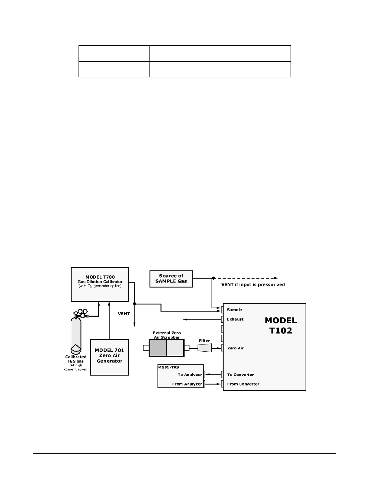
Figure 4-4. Pneumatic Connections for Formal Calibration of Units w/ I ZS Valve Option
Source of
SAMPLE Gas
VENT if input is pres surized
Ambient
Air
MODEL
T102
From Converter
Sample
Zero Air (Scrubber)
Exhaust
Span
M501-TRS
To Converter
From Analyzer
To Analyzer
Figure 4-5. Pneumati c Connections for Informa l Calibration Checks of Units with IZS
Valve Option
NOTE
Gas flow must be maintained at all times for units with IZS Options installed. The IZS
option requires a permeation tube (customer supplied) which emits H2S. Insufficient
gas flow can build up H2S to levels that will damage the instrument.
Remove the permeation device when taking the analyzer out of operation.
07267B DCN6485

Pneumatic Connections Teledyne API - T102/501 TRS, Addendum to T101 Operation Manual
30
4.2. Initial Operation
4.2.1. Startup / Warm Up of the T102
Startup procedures and warm up behavior of the T102 are identical to those described in
the T101 Manual - PN 07266.
Possible Warning Messages at Start-Up
Warning messages for the T102 is the same as the list of warning messages included in
Appendix A: Mode 101E Warnings and Test Measurements in the T101 Manual - PN
07266 with the exception that there is no CONV TEMP WARNING (converter
Temperature Warning).
4.2.2. Functional Check of the T102
To performing an initial functional check of the T102, follow the steps contained in the
Functional Check section in the T101 Manual - PN 07266.
Test Functions
The following diagram supersedes the diagram found in Step 2 of the Functional Check
section in the T101 Manual - PN 07266.
1
Only appears if IZS option is
installed.
2
Only appears if analog output A4
is actively reporting a test function.
3
Shown as they appear when analyzer
is in TRS mode. In SO2 mode appear as SO2 STB, SO2 OFFS &
SO2 SLOPE. In multigas mode, both versions appear.
RANGE
TRS STB
3
PRES
SAMP FL
PMT
NORM PMT
UV LAMP
LAMP RATIO
STR. LGT
DARK PMT
DARK LAMP
TRS SLOPE
3
TRS OFFS
3
HVPS
RCELL TEMP
BOX TEMP
PMT TEMP
IZS TEMP
1
TEST
2
TIME
SAMPLE RANGE = 500.0 PPB TRS = X.X
< TST TST >
CAL
SETUP
Refer to the T101
Manual for
definitions of these
test functions.
Toggle
<TST TST> to scroll
through list of functions
07267B DCN6485

Teledyne API - T102/501 TRS, Addendum to T101 Operation Manual Pneumatic Connections
31
4.2.3. Startup / Warm Up of the M501-TRS
After electrical and pneumatic connections are made, turn on the instrument and pump
power. The exhaust fan should start.
The M501-TRS’ temperature controller is preprogrammed at the factory so no special
setup operation is required. The temperature controller (see Figure 4-6) should
immediately come on in operation mode: the current temperature of the converter oven
should the display immediately appear in the display area and the process value (PV)
LED should be lit.
It may take as much as 30 minutes for the oven to reach its nominal operating
temperature.
During that initial warm up period the high and low alarms and the M501-TRS single
alarm output are disabled. Both the internal alarms and the alarm output will be
automatically enabled once the converter oven temperature rises above the lower alarm
limit.
Figure 4-6. M501-TRS Temperature Controller Startup
07267B DCN6485

Pneumatic Connections Teledyne API - T102/501 TRS, Addendum to T101 Operation Manual
32
4.3. Initial Calibration
Initial calibration of the T102 should be performed with:
• Zero air supplied by a zero air generator such as the TAPI Model 701;
• Calibrated H
2
S span gas of the appropriate concentration:
• With external pneumatic connections as described in Figure 4-1 through
Figure 4-5 of this addendum, and;
• Using the i n formation and procedure included in the Initial Calibration
section in the T101 Manual - PN 07266.
No initial calibration of the M501-TRS instrument is required.
NOTE
Once you have completed the above set-up procedures, please fill out the quality
questionnaire that was shipped with your unit and return it to TAPI. This informat i on
is vital to our efforts in continuously improving our service and our product s . Thank
you.
07267B DCN6485

33
5. OPTIONAL HARDWARE AND SOFTWARE
This section includes descriptions of the hardware and software options available for the
Model T102 analyzer and M501-TRS converter that are different from or not included in
the Options section of the T101 Manual - PN 07266. For all other available options see
that manual.
For assistance with ordering these options please contact the sales department of TAPI
at:
TOLL-FREE:
800-324-5190
TEL:
+1 858-657-9800
FAX:
+1 858-657-9816
E-MAIL:
apisales@teledyne.com
WEB SITE:
http://www.teledyne-api.com
5.1. Rack Mount Kits (Options 20a, 20b, 21, 22 & 81)
The following table supersedes the table included in Rack Mount Kits (Option 20a, 20b
& 21) section in the T101 Manual - PN 07266.
OPTION NUMBER DESCRIPTION
OPT 20A
Rack mount brackets with 26 in. chassis slides.
OPT 20B
Rack mount brackets with 24 in. chassis slides.
OPT 21
Rack mount brackets only
OPT 22
Rack Mount for M501-TRS
OPT 81
Rack Mount for M501-TRS with slides
5.2. Calibration Valves Options
5.2.1. Zero/Span Valves (Option 5 0 ) & Inte rna l Zero/Span Gas Generator
(Option 51)
The description of the construction and operation for the zero span and IZS valve
options for the T102 TRS is identical to that information contained in Calibration Valves
Option section in the T101 Manual - PN 07266.
However, the internal pneumatic flow or the T102 with either of these options installed
is different. See:
• Figure 5-1 for an illustration of t he T102 internal gas flow with the
zero/span valves option
• Figure 5-2 for an illustration of t he T102 internal gas flow with the IZS
valve option
07267B DCN6485

OPTIONAL HARDWARE AND SOFTWARE Teledyne API - T102/501 TRS, Addendum to T101 Operation Manual
34
3
2
1
SAMPLE/CAL
VALVE
ZERO/SPAN
VALVE
3 2
1
2
3
1
SPAN GAS INLET
ZERO AIR INLET
VACUUM MANIFOLD
FLOW
CONTROL
ASSY
EXHAUST TO OUTER
LAYER OF KICKER
SAMPLE FILTER
T102
INSTRUMENT
CHASSIS
EXHAUST GAS
OUTLET
KICKER EXHAUST
TO PUMP
HYDROCARBON
SCRUBBER
(KICKER)
UV
LAMP
PMT
SAMPLE
CHAMBER
FLOW
SENSOR
FLOW / PRESSURE
SENSOR PCA
SAMPLE
PRESSURE
SENSOR
PUMP
TRS / SO2
MODE
VALVE
Gas Flow in SO2 phase
of multigas mode or
when in SO2
measurement mode
TO
CONVERTER
FROM
CONVERTER
M501-TRS
SO
2
Scrubbe
r
CONVERTER OVEN
TRS SO
2
TO
ANALYZER
FROM
ANALYZER
SAMPLE GAS
INLET
Figure 5-1. Internal Pneumatic Diagram of the T102 With Z/S Option Installed
The following table describes the state of each valve during the analyzer’s various
operational modes.
Table 5-1. Zero/Span Valve Operating States
MODE VALVE CONDITION VALVE PORT
CONNECTION
(FIG. 5-2)
SAMPLE
Sample/Cal Open to SAMPLE inlet
3 2
Zero/Span Open to ZERO AIR inlet
3 2
ZERO CAL
Sample/Cal Open to zero/span inlet
1 2
Zero/Span Open to ZERO AIR inlet
3 2
SPAN CAL
Sample/Cal Open to zero/span inlet
1 2
Zero/Span Open to SPAN GAS inlet
1 2
07267B DCN6485

Teledyne API - T102/501 TRS, Addendum to T101 Operation Manual OPTIONAL HARDWARE AND SOFTWARE
35
`
FLOW
SENSOR
FLOW / PRESSURE
SENSOR PCA
SAMPLE
PRESSURE
SENSOR
EXHAUST TO OUTER LAYER
OF KICKER
3
2
1
SAMPLE/CAL
VALVE
ZERO/SPAN
VALVE
3 2
1
2
3
1
ZERO AIR INLET
VACUUM MANIFOLD
CRITICAL
FLOW
ORIFICE
SAMPLE
FILTER
T102
INSTRUMENT
CHASSIS
EXHAUST GAS
OUTLET
KICKER EXHAUST
TO PUMP
HYDROCARBON
SCRUBBER
(KICKER)
UV
LAMP
PMT
SAMPLE
CHAMBER
PUMP
TRS / SO2
MODE
VALVE
Gas Flow in SO2 phase
of multigas mode or
when in SO2
measurement mode
TO
CONVERTER
FROM
CONVERTER
M501-TRS
SO
2
Scrubbe
r
CONVERTER OVEN
TRS SO
2
TO
ANALYZER
FROM
ANALYZER
SAMPLE GAS
INLET
IZS
Permeation Tube
SO2 Source
ZERO AIR
SCRUBBER
CRITICAL
FLOW
ORIFICE
Figure 5-2. Internal Pneumatic Diagram of the T102 with IZS Options Installed
The following table describes the state of each valve during the analyzer’s various
operational modes.
Table 5-2. IZS Valve Operating St ate s
MODE VALVE CONDITION VALVE PORT
CONNECTIONS
SAMPLE
Sample/Cal Open to SAMPLE inlet
3 2
Zero/Span Open to ZERO AIR inlet
3 2
ZERO CAL
Sample/Cal Open to zero/span valve
1 2
Zero/Span Open to ZERO AIR inlet
3 2
SPAN CAL
Sample/Cal Open to zero/span valve
1 2
Zero/Span Open to SPAN GAS inlet
1 2
07267B DCN6485

OPTIONAL HARDWARE AND SOFTWARE Teledyne API - T102/501 TRS, Addendum to T101 Operation Manual
36
This page intentionally left blank.
07267B DCN6485

37
6. T102 OPERATING I NSTRUCTIONS
NOTE
For the most part the operation instruction for the T102are the same as those
described in Chapter 6 of the T101 Manual - PN 07266 with the exception that the
terms “TRS” & “total reduced sulfur” should be substituted for the terms “H2S” &
“hydrogen sulfide ” unless ot herwise stated in this a ddendum.
6.1.1. T102 Analog Output Signals
The information contained in the available Analog Output Signals section in the T101
Manual - PN 07266 is correct except that the test channel output is located on analog
output A3 rather than A4 .
ANALOG OUT
A1 A2 A3 A4
+ - + - + - + -
SO2 concentration
outputs
HIGH range when
DUAL mode is selected
Test Channel
Not Used
LOW range when
DUAL mode is selected
Figure 6-1. Analog Output Connector
NOTE
On analyzers with the SO2-TRS multigas gas measurement option available, the outputs
of A1 and A2 correspond to:
Output SO
2
SO2 – TRS TRS
Channel Mode Mode Mode
A1
SO2
SO2
TRS
A2
SO2
TRS
TRS
07267B DCN6485

T102 OPERATING INSTRUCTIONS Teledyne API - T102/501 TRS, Addendum to T101 Operation Manual
38
As the instrument switches between TRS mode to SO2 mode , only the reporting range
and analog output associated with the gas currently being measured will be active. The
reporting range and analog output for the gas not being measured will continue to
report the last valid reading.
The output, labeled A3 is special. It can be set by the user (see Test Channel Output
section in the T101 Manual - PN 07266) to output many of the parameters accessible
through the <TST TST> buttons of the units Sample Display.
Output A4 is not available on the Model T102 Analyzer.
6.1.2. Setting the T102 Gas Measurement Mode
Setting the gas measurement mode on the T102 is identical to the method described in
the Setting the Gas Measurement section in the T101 Manual - PN 07266 except that the
available measurement modes are as described in the following table:
Table 6-1. T102 Gas Measurement Modes
GASMODE DESCRIPTION
TRS
The sample gas stream is stripped of any ambient SO
2
by a special
chemical scrubber, then passed through a catalytic converter that
changes the TRS present in to S O2 which is then measured using the
UV Fluorescence method
SO2
The sample gas stream bypasses the SO
2
Scrubber and catalytic
converter allow ing the only ambient SO
2
to be measured.
TRS –SO2
The switching valve alternates the gas stream between the two paths
at regular interv a ls allowing the in s trument to measur e b oth gases.
6.2. SETUP – DIAG: Using the Diagnostics Functions
6.2.1. T102 Analog I/O Configuration
The following table supersedes the Analog Output Pin Assignments table in the Analog
I/O Configuration section of the T101 Manual - PN 07266
Table 6-2. Analog Output Pin Assignments
PIN ANALOG
OUTPUT
VOLTAGE
SIGNAL
CURRENT
SIGNAL
1
A1
V Out I Out +
2 Ground I Out 3
A2
V Out I Out +
4 Ground I Out 5
A3
V Out not available
6 Ground not available
7-8
A3
Not Used Not Used
See Figure 3-4 for the location of the analog output connector on the instrument’s rear
panel.
07267B DCN6485

Teledyne API - T102/501 TRS, Addendum to T101 Operation Manual T102 OPERATING INSTRUCTIONS
39
6.2.2. T102 Test Channel Output
The following table supersedes the Test Parameters Available for Analog Output A4
table in the Test Channel Output section in the T101 Manual - PN 07266
Table 6-3. Test Parameters Available for Analog Output A4
TEST CHANNEL TEST PARAMETER RANGE 1
NONE Test channel is turned off
PMT READING 0-5000 mV
UV READING 0-5000 mV
SAMPLE PRESSURE 0-40 in-Hg-A
SAMPLE FLOW 0-1000 cm³/min
RCELL TEMP 0-70° C
CHASSIS TEMP 0-70° C
IZS TEMP 0-70° C
PMT TEMP 0-50° C
CHASSIS TEMP 0-70° C
HVPS VOLTAGE 0-5000 V
1
This refers to the voltage r a nge of the parameter and
not the output sign a l of the test channel.
Once a TEST function is selected, the instrument begins to report a signal on the A36
output and adds TEST= to the list of test functions viewable on the display (just before
the TIME display).
6.3. SETUP – COMM: Setting Up the T102’s Communication Ports
6.3.1. T102 ID Code
The default ID code for all T102 analyzers is 102.
To edit the instrument’s ID code, see Analyzer ID Section of the T101 Manual - PN
07266.
6.3.2. T102 Ethernet Host Name
The default name for all TAPI Model T102 analyzers is T102.
To change the Ethernet Host Name see Changing the Analyzer’s HOSTNAME section in
the T101 Manual - PN 07266.
07267B DCN6485

T102 OPERATING INSTRUCTIONS Teledyne API - T102/501 TRS, Addendum to T101 Operation Manual
40
6.4. Remote Operation of the Analyzer
6.4.1. Control Inputs
The following table and figures supersede the Control Input Pin Assignment table and
the figures for Control Inputs with Local 5 V Power Supply and Control Input with
External 5 V Power Supply in the Control Inputs section in the T101 Manual - PN
07266 respectively.
Table 6-4. T102 Control Input Pin Assignments
INPUT STATUS CONDITION WHEN E NA BLED
A External Zero Cal
Zero calibration m ode is activated. T he mode field of the
display will read ZERO CAL R.
B External Span Cal
Span calibration mode is activated. T he mode field of the
display will read SPAN CAL R.
C, D, E, & F
Unused
Digital Ground Provided to ground an external device (e.g., r ec order).
U
DC Power For
Input Pull Ups
Input for +5 VDC r eq uired to activate inpu ts A - F. This voltag e
can be taken from an external sourc e or from the “+” pin.
+
Internal +5v
Supply
Internal source of +5V which can be used to activate inputs
when connected to pin U.
CONTROL IN
A B C D E F U +
SPAN
ZERO
Figure 6-2. Control Inputs with Local 5 V Power Supply
07267B DCN6485

Teledyne API - T102/501 TRS, Addendum to T101 Operation Manual T102 OPERATING INSTRUCTIONS
41
CONTROL IN
-
+
5 VDC Power
Supply
LOW SPAN
ZERO
SPAN
A B C D E F U +
Figure 6-3. Control Inputs with External 5 V Power Supply
6.4.2. Using the T102 with a Hessen Protocol Network
6.4.2.1. T102 Hessen Protocol Gas ID List.
The default Hessen Gas Id’s for all T102 analyzers are:
Table 6-5. T102 Default Hessen Gas ID’s
Gas Type Hessen Gas ID
SO2 111
TRS 112
To edit the instrument’s ID code, see the Hessen Protocol Gas ID section in the T101
Manual - PN 07266.
07267B DCN6485

T102 OPERATING INSTRUCTIONS Teledyne API - T102/501 TRS, Addendum to T101 Operation Manual
42
6.4.2.2. Setting Hessen Protocol Status Flags
The following table supersedes the Setting Hessen Protocol Status Flags Table in the
T101 Manual - PN 07266 /
Table 6-6. Default Hessen Status Bit Assignments
STATUS FLAG NAME
DEFAULT BIT
ASSIGNMENT
WARNING FLAGS
SAMPLE FLOW WARNING 0001
PMT DET WARNING 0002
UV LAMP WARNING 0002
HVPS WARNING 0004
DARK CAL WARNING 0008
RCELL TEMP WARNING 0010
IZS TEMP WARNING 0020
PMT TEMP WARNING 0040
CONV TE M P WARNING 1050
OPERATIONAL FLA GS
In Manual Calibration Mode 0200
In Zero Calibration Mode 0400
In Span Calibration Mode 0800
UNITS OF MEASURE FLAGS
UGM 0000
MGM 2000
PPB 4000
PPM 6000
SPARE/UNUSED BITS 0080, 0100, 1000,
8000
UNASSIGNED FL A G S
Box Temp Warning Front Panel Warning
Sample Press Warning Analog Cal Warning
System Reset Cannot Dyn Zero
Rear Board Not Detected Cannot Dyn Span
Relay Board Warning Invalid Conc
07267B DCN6485

43
7. M501-TRS OPERATING INSTRUCTIONS
CAUTION!
DO NOT OPERATE WITHOUT THE COVER INSTALLED ON THE
M501TS CONVERTER. OVEN TEMPERATURE WILL NOT REGULATE
PROPERLY WITHOUT THE COVER IN PLACE.
NOTE:
Changing the Converter temperature from the value preprogrammed at the factory
may have undesirable effects on TRS converter’s efficiency.
Do not change the factory-preprogrammed value unles s absolutely necessary or
unless directed to do so by TAPI Technical Support.
7.1. Basic M501-TRS Controls
Figure 7-1. M501-TRS Temperature Controls
07267B DCN6485

M501-TRS OPERATING INSTRUCTIONS Teledyne API - T102/501 TRS, Addendum to T101 Operation Manual
44
Table 7-1. M501-TRS Temperature Controls and Definitions
NAME FUNCTION
Process Value A 4-digit, 7 segment LED display on wh ich the current value of the PV and as
well as error codes and programming parameters and data are all displayed.
Set Value A 4-digit, 7 segment LED display which shows th e cu rre nt value of the S V. It
also displays the the param eter s ettings in parameter setting mode
It flickers during Standyby Mode.
Select Key This key is used to switch between the 1st, 2nd or 3rd parameter block . It is
sued to switch between the para m eter a nd the data at the 1
st
, 2nd and 3rd
block.
To access the 1st parameter block press an d hold the select key for 1 sec.
To access the 2nd parameter block press an d hold the select key for 3 sec.
To access the 3rd parameter block press and hold the select key for 5 sec.
To return to the main display after entering a paremeter bl ock press and hold
the key for 2 sec.
Used to confirm parameter value changes by pressing onc e.
Set value
Indicator
Is lit indicates when a the set value (SV) is displayed.
Up Key Used to increase the numerical value. The numerical value is increased by
pressing the key once. Th e numerical value keeps oon increasing by pressing
the key continuously.
Used to search for parameters within the 1
st
, 2nd and 3rd blocks.
Down Key Used to decrease the n umerical value. The numeric a l v a lue is increased by
pressing the key once. Th e numerical value keeps oon increasing by pressing
the key continuously.
Used to search for parameters within the 1
st
, 2nd and 3rd blocks.
Autotune
Indicator
The lamp blinks while the PID autotuning or self tuning is being performed.
Control
Indicator
Lit when the controller is actively c ontrolling the heater temperatu re.
Alarm
Indicator1
(AL1)
Lit when the PV equ a ls or exceeds the upper alarm limit.
Alarm
Indicator2
(AL2)
Lit when the PV equ a ls or falls below the low e r a larm limit.
07267B DCN6485

Teledyne API - T102/501 TRS, Addendum to T101 Operation Manual M501-TRS OPERATING INSTRUCTIONS
45
7.2. To Display The Current Temperature
If the Process Value is displaying a numerical value, the process value is currently
being displayed.
If it is not being displayed press the select key for 2 seconds.
7.3. To Manually Adjust the Converter Oven Temperature
CAUTION !
DO NOT SET THE TEMPERATURE HIGHER THAN 1050 ºC
4. Set the main display to show the current value of the set variable by
pressing the PV/SV mode key.
5. To set each digit:
c. Press the up-arrow under that digit once. The digit will flash.
d. To increment that digit press and hold the UP key until the
appropriate number is displayed.
e. To decrement that digit press and hold the DOWN key until the
appropriate number is displayed.
f. To increment/decrement the 1000’s digit it is necessary to adjust
increment/decrement the 100’s digit up and down. Each time the
100’s digit passes “0” the 1000s digit will increment or decrement
correspondingly. See EXAMPLE table below.
6. Once the desired value is reached, press the ENT key to store the new
set value
7. Return the main display to process mode by pressing the PV/SV mode
button once.
EXAMPLE to change the set value from 950 to equal 1050.
ACTION RESULT
Press the PV/SV mode key The SV indicator w ill lit up and the displa y will
show 950.
Press the 10’s UP key once The 10’s digit will begin to blink
Press the DOWN key The 10’s digit will decremen t f r om “5”. Release
the DOWN key when the 10’s digi t r ea ds “5”.
Press the 100’s UP Key once The 100’s digit will b egin to blink
Press and hold the 100’s UP key Th e 10 0’s digit will increment from “9” . When it
passes “0” the 1000’s digit w ill inc r em ent to “1”.
Release the 100’s UP key.
-- The Display should n ow read “1050”
Press the ENTER key The new set value is recorded
Press the PV/SV mode key The current level of the process value will be
displayed.
07267B DCN6485

M501-TRS OPERATING INSTRUCTIONS Teledyne API - T102/501 TRS, Addendum to T101 Operation Manual
46
7.4. Autotune the Temperatur e Con t r olle r
The M501-TRS controller includes an auto tune feature which allows the controller to
find and set optimum values for various process control parameters so that the controller
can establish and maintain the converter oven at the temperature set value in the most
stable and efficient manner.
NOTE
Before initiating the autotune feature make sure that the converter temperature oven
has reached a stable, constant temperature.
7.4.1. Initiating the Autotune P rocess
1. Press the SELECT key once. The main display will show
2. Use the SELECT , DOWN or 100’s UP key to scroll through the primary
menu parameters until the display shows
(AT =Autotune).
3. Press the DATA key once. The display will show
(zero = Off).
4. Press the 1’s UP key once. The display will show
(1 = autotune based
on set point value).
5. Press the ENTER key to begin the autotune process. A blinking decimal
point will appear at the bottom right-hand corner of the main display.
6. Wait until the blinking light stops. This may take up to 30 minutes.
7. The autotune process is finished. The autotune p arameter value will
automatically reset to zero (off).
8. Press the PV/SV mode key to return to operational mode.
Note
The P-I-D parameters calculated by aut otu nin g will be retaine d even if the power is
lost. However, if the power is turned off during the auto-tuning process, you must
restart autotuning.
07267B DCN6485

Teledyne API - T102/501 TRS, Addendum to T101 Operation Manual M501-TRS OPERATING INSTRUCTIONS
47
7.4.2. Aborting the Autotune Process
1. Press the DATA key once. The display will show (1).
2. Press the 1’s UP key once. The
will begin blinking
3. Press the DOWN key once. The display will show
(zero).
4. Press the ENTER k e y on ce.
5. Press the PV/SV mode key to return to operational mode.
Note
Auto-tuning MUST to be repeated if there is a significant change in the set value.
If the temperature begins to oscillate excessively around the set value, it may be
necessary to repeat the autotune procedure.
7.5. M501TRS Alarm Relay Adjustment
To set the High and Low Alarm points:
1. Press the SELECT key once. T he main display will show
2. Use the SELECT , DOWN or 100’s UP key to scroll through the primary
menu parameters until the display shows either
(AL = Alarm Low)
or
(AH = High Alarm) .
3. Press the DATA key once. The current value of the alarm limit will be
displayed.
4. To set each digit:
a. Press the up-arrow under that digit once. The digit will flash.
b. To increment that digit, press and hold the digit until the appropriate
number is displayed.
c. To decrement that digit press and hold the DOWN key until the
appropriate number is displayed.
d. To increment/decrement the 1000’s digit it is necessary to adjust
increment/decrement the 100’s digit up and down. Each time the
100’s digit passes “0” the 1000s digit will increment or decrement
correspondingly.
5. Once the desired value is reached, press the ENT key to store the new
set value
6. Press the PV/SV mode key to return to operational mode.
07267B DCN6485

M501-TRS OPERATING INSTRUCTIONS Teledyne API - T102/501 TRS, Addendum to T101 Operation Manual
48
This page intentionally left blank.
07267B DCN6485

49
8. CALIBRATION PROCEDURES
8.1. T102 Calibration
Calibration of the T102 should be performed according to the procedures described in
the Calibration Procedures and EPA Protocol Calibration Chapters in the T101 Manual
- PN 07266.
NOTE
It is recommended that the T102 be calibrated in TRS gas measurement mode using
H2S as a span gas.
If you are using the T102 for US-EPA controlled monitoring of SO2, see the EPA
Protocol Calibration Chapter in the T101 Manual (PN 07266) for information on the
EPA calibration protocol.
8.2. M501-TRS Calibration
The M501-TRS converter does not require field calibration.
07267B DCN6485

CALIBRATION PROCEDURES Teledyne API - T102/501 TRS, Addendum to T101 Operation Manual
50
This page intentionally left blank.
07267B DCN6485

51
9. INSTRUMENT MAINTENANCE
The following table supersedes the T101 Preventative Maintenance Table in the Maintenance Schedule section in the T101 Manual - PN 07266.
Table 8-1. T102 Preventive Maintenance Schedule
ITEM ACTION FREQUENCY
CAL
CHECK
T101 MANUAL
SECTION
DATE PERFORMED
M501 SO2 scrubber
Replace scrubber
material
As required Yes
9.1.1.3 of this
addendum
1
Particulate filter Change particle filter Weekly
No 9.3.1
Verify test functions Review and evaluate Weekly No Appendix C
Zero/span check
Evaluate offset and
slope
Weekly -- 7.3, 7.6, 7.9
1
Zero/span
calibration
Zero and span
calibration
Every 3 months
--
7.2, 7.4, 7.5, 7.7,
7,8
1
External zero air
scrubber (option)
Exchange chemical Every 3 months
No 9.3.4
1
Perform flow check Check Flow Every 6 Months No 11.5.2
1
Sample chamber
optics
Clean windows and
filters
Annually or as
necessary
Yes 9.3.6
1
Critical flow orifice
& sintered filters
Replace Annually
Yes 9.3.7
Internal IZS
Permeation Tube
Replace Annually YES 9.3.2
Perform pneumatic
leak check
Verify Leak Tight
Annually or after
repairs involving
pneumatics
Yes 11.5.1
2
Pump diaphr agm Replace
Every 2 years, or as
necessary
Yes
See instruction in
diaphragm kit
PMT sensor
hardware calibration
Low-level hardware
calibration
On PMT/ preamp
changes if 0.7 < SLOPE
or SLOPE >1.3
Yes 11.5.4
Desiccant bags Replace
Any time sensor assy
inspection plate is opened
(reference Section 11.5.3
)
1
These Items are required to maintain full warranty, all other items are strongly recommended.
2
A pump rebuild kit is available from TAPI Technical Support including all ins tructions and required parts (see Appendix B for part numbers).
07267B DCN6485

07267B DCN6485

53
9.1. Additional and Updated Maintenance Procedures
The following procedures need to be performed regularly as part of the standard
maintenance of the Mod el T102.
9.1.1. Maintaining the SO2 Scrubber
This section supersedes the Changing the SO2 Scrubber Material section in the T101
Manual - PN 07266.
Unlike the T101 which includes an internal scrubber to remove SO
2
from the sample gas
before the H
2
S SO2 conversion takes place, the T102 relies on the SO2 scrubber of the
M501-TRS to perform the same function.
The SO
2
scrubber of your M501-TRS utilizes a consumable compound to absorb SO2
from the sample gas before the TRS is converted to SO
2
. This material must be replaced
periodically in order for the analyzer to continue measuring TRS accurately and
reliability.
This material is capable of efficiently scrubbing SO
2
for up to 1000 ppm-hours. This
means that if the SO
2
content of the sample gas is typically around 100 ppb, the scrubber
will function for approximately 10,000 hours, a little over 13 months. If, however, the
typical ambient SO
2
level of the sample gas is 250 ppb, the scrubber would only last for
approximately 4000 hours or about 5 ½ months.
9.1.1.1. Predicting When to Replace the SO2 Scrubber
To determine how long the SO2 scrubber will operate efficiently:
1. Measure the amount of SO2 in the sample gas.
• If your T102 has the multigas measurement options activated, this
can be done by following inst ructions found in the Setting the Gas
Measurement Mode section in the T101 Manual (PN 07266) and
selecting MEASURE MODE = SO
2
.
• Let the analyzer operate for 30 minutes, then note the SO
2
concentration.
2. Divide 1 000 by the SO
2
concentration.
EXAMPLE: If the SO
2
concentration is 125 ppb:
Operational hours = 1000 ppm/hr ÷ 0.125 ppm
Operational hours = 100 000 ppb/hr ÷ 125 ppb
Operational hours = 8000 hrs
07267B DCN6485

INSTRUMENT MAINTENANCE Teledyne API - T102/501 TRS, Addendum to T101 Operation Manual
54
9.1.1.2. Checking the Function of the SO2 Scrubber
To check to see if your SO2 scrubber is operating properly perform the following test:
1. Set the analyzer for TRS gas measurement mode (see Setting the Gas
Measurement Mode section in the T101 Manual - PN 07266).
2. Set the reporting range to range of 1000 PPB (see Sections 6.7.4, 6.7.5
and 6.7.6 of the T101 Manual - PN 07266).
3. Introduce a gas mixture into the sample gas stream that includes 500
PPB of SO
2
.
An increase of more than 10 PPB in the TRS reading is an indication that the efficiency
of the scrubber is decreasing to the point that the absorbing material should be replaced.
9.1.1.3. Changing the SO2 Scrubber Material
1. Input zero air for 5 minutes
2. Turn off the M501-TRS
3. Locates the SO2 scrubber cartridge on the right side of the converter:
It looks like a big white cylinder (See Figure 3-2 of this addendum).
4. Undo the two 1/4 inch fittings on the top of the scrubber
5. Remove the two screws holding the scrubber to the instrument chassis
and remove the scrubber
6. Take the two Teflon fittings off the instrument.
7. Empty the SO
2
scrubbing material into a hazmat bin.
8. Fill each side of the scrubber with new SO2 scrubber material until it is
½ inch from the bottom of the thread lines (about 1 inch from the to p of
the scrubber), do not fill it too high or the fitting will compact the
material, causing a restriction in the gas flow.
9. Remove the Teflon tape from both of the removed fittings, and wra p
them with new Teflon tape.
10. Install both fittings back onto the scrubber.
11. Put the scrubber back into the a nalyzer and replace the two screws on
the bottom.
12. Screw the two 1/4” fittings back onto the top of the scrubber (either
fitting can fit the inlet or the outlet). Return analyzer to normal
operation
07267B DCN6485

55
10. THEORY OF OPERATION
The T102 is a modified T101 which, when used in conjunction with a M501-TRS
determines the concentration of total reduced sulfur (TRS), in a sample gas drawn
through the instrument In most ways the theory of operation of the T102 & M501-TRS
system is identical to the T101 theory of operation as described in the Theory of
Operation Chapter in the T101 Manual - PN 07266.
This section describes those areas where differences between the T102 and the T101
exist as well as updated information made available since the publication date of the
T101 Manual - PN 07266.
10.1. Measurement Principle
This section supersedes the Measurement Principle section in the T101 Manual - PN
07266
10.1.1. TRS Conversion
The T102 TRS analyzer is basically an SO2 analyzer with a TRS SO2 converter (the
M501-TRS) inserted into the gas stream before the sample gas enters the sample
chamber.
The M501-TRS, receives sample gas from the T102 after it has been passed through a
particulate filter and has been scrubbed of hydrocarbon interferents. Once inside the
M501-TRS the sample gas is scrubbed of all naturally occurring SO
2
, then passed
through a special quartz converter which heats the gas to a very high temperature
causing it to react with the O
2
present in the sample gas creating SO2 in the following
manner .
TRS + O2 SO2
Equation 10-1
For TRS compounds, the converter is most efficient when it operates at 850°C,
converting >95% of the TRS into SO
2
. The c onverter temperature is viewable via the
front panel of the M501-TRS
When the converter is operating at peak efficiency there is a nearly 1:1 relationship
between the amount of TRS entering the converter and the amount of SO
2
leaving it.
Therefore, by measuring the amount of SO
2
in the gas after it leaves the converter, the
amount of TRS originally present on the sample gas can be directly inferred.
07267B DCN6485

THEORY OF OPERATION Teledyne API - T102/501 TRS, Addendum to T101 Operation Manual
56
10.1.2. SO2 Ultraviolet Fluorescence
The physical principle upon which the T102’s measurement method is based is the
fluorescence that occurs when sulfur dioxide (SO
2
) is changed to an excited state (SO2*)
by ultraviolet light with wavelengths in the range of 190 nm-230 nm. This reaction is a
two-step process.
The first stage (Equation 9-2) occurs when SO
2
molecules are struck by photons (hv) of
the appropriate ultraviolet wavelength. (In the case of the Model T102, a band pass filter
between the source of the UV light and the affected gas limits the wavelength of the light to
approximately 214 nm). The SO
2
absorbs some of energy from the UV light causing one
of the electrons of each of the affected SO
2
molecules to move to a higher energy orbital
state.
*
22142
SOhvSO
Ia
nm
→+
Equation 10-2
The amount of SO2 converted to SO2* in the sample chamber is dependent on the
average intensity of the UV light (Ia) and not its peak intensity because the intensity of
UV light is not constant in every part of the sample chamber. Some of the photons are
absorbed by the SO
2
as the light travels through the sample gas.
Figure 10-1. UV Absorption in the T102 Reaction Cel l
The equation for defining the average intensity of the UV light (Ia) is:
( )( )
[ ]
20
SOaxexp1IIa −−=
Equation 10-3
Where:
I
0
= Intensity of the excitation UV light.
a = The absorption coefficient of SO
2
(a constant).
SO
2
= Concentration of SO
2
in the sample chamber.
x = The distance between the UV source and the SO
2
molecule(s) being
affected (path length).
07267B DCN6485

Teledyne API - T102/501 TRS, Addendum to T101 Operation Manual THEORY OF OPERATION
57
The second stage of this reaction occurs after the SO2 reaches its excited state (SO2*).
Because the system will seek the lowest available stable energy state, the SO
2
* molecule
quickly returns to its ground state (Equation 10-3) by giving off the excess energy in the
form of a photon (h
ν
). The wavelength of this fluoresced light is also in the ultraviolet
band but at a longer (lower energy) wavelength centered at 330nm.
nm33022
hvSO*SO + →
Equation 10-4
The amount of detectable UV (F) given off by the decay of the SO2* is affected by the rate
at which this reaction occurs (k).
( )
*SOkF
2
=
Equation 10-5
Where:
F = the amount of fluorescent light given of f.
k = The rate at which the SO
2
* decays into SO
2.
SO2*
= Amount of excited state SO
2
in the sample chamber.
Therefore:
( )
nm
kF
hvSOSO
33022
* +→
Equation 10-6
Furthermore, the function (k) is affected by the temperature of the gas. The warmer the
gas, the faster the individual molecules decay back into their ground state and the more
photons of UV light are given off per unit of time.
Given that the absorption rate (a) of SO
2
is constant, the amount of fluorescence (F) is a
result of:
• The amount of SO2* created which is affected by the variable factors
from equation 10-2 above: concentration of SO
2
; intensity of UV light
(
I
0
); path length of the UV light (x) and;
• The amount of fluorescent light created which is affected by the variable
factors from equation 10-5: the amount of SO
2
* present and the rate of
decay (k) which changes based on the temperature of the gas.
The amount of fluorescent light emitted (F) is directly related to the concentration of the
SO
2
in the Sample Chamber, when:
• the intensity of the light (I0) is known
• the path length of excitation light is short (
x)
• the temperature of the gas is known and compensated for so that the rate
of SO
2
*decay is constant (k)
• there are no interfering conditions present (such as interfering gases or
stray light)
07267B DCN6485

THEORY OF OPERATION Teledyne API - T102/501 TRS, Addendum to T101 Operation Manual
58
The Teledyne API UV Fluorescence SO2 Analyzer is specifically designed to create
these circumstances.
• The light path is very short (x).
• A reference detector measures the intensity of the available excitation UV
light and is used to remove effects of lamp drift(
I
0
).
• The temperature of the sample gas is measured and controlled via
heaters attached to the sample chamber so that the rate of decay (k) is
constant.
• A special hydrocarbon scrubber removes the most common interfering
gases from the sample gas.
• And finally, the design of the sample chamber reduces the effects of
stray light via its optical geometry and spectral filter ing.
The net result is that any variation in UV fluorescence can be directly attributed to
changes in the concentration of SO
2
in the sample gas.
10.2. The UV Light Path
The following information is in addition to that contained in the UV Light Path section
in the T101 Manual - PN 07266.
10.2.1. UV Lamp Shutter & PMT Offset
Inherent in the operation of both the reference detector and the PMT are minor
electronic offsets. The degree of offset differs from detector to detector and from PMT
to PMT and can change over time as these components age.
To account for these offsets the T102 includes a shutter, located between the UV Lamp
and the source filter, that periodically cuts off the UV light from the sample chamber.
This happens every 30 minutes. The analyzer records the outputs of both the reference
detector and the PMT during this dark period and factors them into the SO
2
concentration calculation .
• The reference detector offset is stored as and viewable via the front
panel as the test function DRK LMP.
• The PMT offset is stored as and viewable via the front panel as the test
function DRK PMT
07267B DCN6485

Teledyne API - T102/501 TRS, Addendum to T101 Operation Manual THEORY OF OPERATION
59
10.3. Pneumatic Operation
10.3.1. Sample gas Flow
See Figures 3-4. 4-1 and 4-2 for depictions of the internal pneumatic flow of both the
T102 & the M501-TRS.
10.3.2. M501 SO2 Scrubber
In order to ensure that no ambient SO2 interferes with the analyzer’s TRS measurement
the sample gas stream is passed through a chemical scrubber that removes SO
2
from the
sample stream before it is passed though the M501-TRS converter oven.
The SO
2
scrubber is a Teflon encased, stand-alone unit containing a room-temperature
catalyst tube mounted in the right side of the converter case (see Figure 3.2).
The SO
2
scrubber material is consumed as it removes SO2. If the expected
concentrations of SO
2
are very high, the lifetime of the scrubber will be short. The
expected life of the scrubber is approximately 1000 ppm-hours. See Section 8.1.1.3 for
information on when and how to replace the SO
2
scrubber material)
07267B DCN6485

THEORY OF OPERATION Teledyne API - T102/501 TRS, Addendum to T101 Operation Manual
60
10.4. Electronic Operation
10.4.1. Sensor Module
This Section replaces the Sensor Module and Sample Chamber section in the T101
Manual - PN 07266.
Electronically, the T102 sensor module is a group of components that: create the UV
light that initiates the fluorescence reaction between SO
2
and O3; sense the intensity of
that fluorescence and generate various
electronic signals needed by the analyzer to
determine the SO
2
concentration of the sample gas (see Section 9.1) and sense and
control key environmental conditions such as the temperature of the sample gas and the
PMT.
Figure 10-2. T102 Sensor Module
These components are divided into two significant subassemblies. The sample chamber
and the PMT assembly.
• Figure 9-3 shows an exploded view of the sample chamber assembly
• Figure 9-5 shows an exploded view of the PMT Assembly
07267B DCN6485

Teledyne API - T102/501 TRS, Addendum to T101 Operation Manual THEORY OF OPERATION
61
10.4.1.1. Sample Chamber
The main electronic components of the sample chamber are the reference detector(see
the Reference Detector section in the T101 Manual - PN 07266); the UV Lamp (see the
UV source Lamp section in the T101 Manual - PN 07266) and its electronically operated
shutter (see Section 10.2.1 of this addendum); and the sample chamber heating circuit,
Figure 10-3. T102 Sample Chamber
10.4.1.2. Sample Chamber Heating Circuit
In order to reduce temperature effects, the sample chamber is maintained at a constant
50°C, just above the high end of the instrument’s operation temperature range. Two AC
heaters, one embedded into the top of the sample chamber, the other embedded directly
below the reference detector’s light trap, provide the heat source. These heaters operate
off of the instrument’s main AC power and are controlled by the CPU through a power
relay on the relay board. A thermistor, also embedded in the bottom of the sample
chamber, reports the cell’s temperature to the CPU through the thermistor interface
circuitry of the motherboard.
07267B DCN6485

THEORY OF OPERATION Teledyne API - T102/501 TRS, Addendum to T101 Operation Manual
62
10.4.2. M501-TRS Electronics
Electronically the M501-TRS is a simple device. The nucleus of the instrument is a
programmable, P-I-D temperature controller that manages the temperature of the
instrument’s AC powered converter oven based on analog input from the thermocouple
attached to the converter’s chamber.
HEATER
AC Heater
Control Relay
Quartz Converter Tube
Thermocouple
P-I-D
CONTROLLER
SPST ALARM
Thermal
Switch
Alarm Output
Connector
M501-TRS
Figure 10-4. M501-TRS Electronic Block Diagram
The P-I-D controller determines the differences between the actual temperature (called
the Process Value or PV) of the oven, compares it to the target temperature (called the
Set Point or SV) and changes the percentage of time the heater is turned on versus t he
time it is turned off accordingly. The higher the proportion of ON-time versus OFF-time
the faster the oven is heated. For instance, if the PV is much lower than the SV the P-I-D
will keep the heater turned on 100% of the time resulting in a relatively rapid increase in
the temperature of the oven. As the PV approaches the same temperature as the SV the
ON cycles get shorter compared to the OFF cycles.
The M501-TRS’s P-I-D controller includes sophisticated software that allows the
controller to track the rate change in temperature of the oven compared to the percentage
of heater ON-time and predict the proportion needed to reach and maintain the proper
oven temperature with a minimal amount of overshoot or fluctuation.
10.4.2.1. Thermal Switch
While the M501-TRS’s P-I-D Controller includes many safeguards that prevent runaway
heating of the converter oven, as an additional safety backup the M501-TRS includes a
heat sensitive switch which automatically interrupts power to the heater before the oven
temperature reaches critical levels.
07267B DCN6485

Teledyne API - T102/501 TRS, Addendum to T101 Operation Manual THEORY OF OPERATION
63
10.4.2.2. Temperature Alarms and Alarm Output
The M501-TRS’ controller has two user settable alarm points: High Alarm and Low
Alarm. A single SPST alarm output is triggered should the PV rise above the set level
of the high alarm point or fall below the level of the low alarm point.
The relay is normally open, and the contact closes in the alarm condition. The relay
contacts are isolated (dry) SPST, 220VAC / 30 VDC 1 Amp, resistive load. This alarm
output is available via a connector on the rear panel of the M501-TRS.
The M501-TRS temperature controller is programmed to hold off activation of either
alarm until after the process value rises above the lower limit for the first time after
power up.
07267B DCN6485

THEORY OF OPERATION Teledyne API - T102/501 TRS, Addendum to T101 Operation Manual
64
This page intentionally left blank.
07267B DCN6485

65
11. TROUBLESHOOTING and REPAIR
This section includes various troubleshooting and repair information supplemental to
that in the Troubleshooting and Repair section of the T101 manual (PN 07266).
CAUTION
The operations outlined in this section must be performed by qua lified
maintenance personnel only.
Please re a d the Troubleshooting and Repair section of the T101 Manual
(PN 07266) before attempting the following trouble shooting or repair
procedures
WARNING
Risk of electrical shock. Some operations need to be carried out with the
analyzer open and running. Exercise caution to avoid electrical shocks and
electrostatic or mechanical damage to the analyzer. Do not drop tools into
the analyzer or leave those after your procedures. Do not shorten or touch
electric connections with metallic tools while operating inside the
analyzer. Use common sense when operating inside a running an a lyzer.
11.1.1. Fault Diagnosis with Warning Messages
11.1.1.1. T102 Warning Messages
The warning messages for the T102 are identical to those included in the Fault
Diagnosis with Warning Messages section in the T101 Manual (PN 07266) except that
there is no CONV TEMP WARNING.
11.1.1.2. M501-TRS Error Codes
The following error codes may appear on the temperature controller display of the
M501-TRS
07267B DCN6485

TROUBLESHOOTING and REPAIR Teledyne API - T102/501 TRS, Addendum to T101 Operation Manual
66
Table 11-1. Test Functions - Possible Causes for Out -Of-Range Values
ERROR
MESSAGE
CAUSE NOTES
Thermocouple burnt out or wiring between
Thermocouple and Tem perature Controller is open.
The controller process value exceeds the upper
input range set point by 5% of full scale.
Controller will automatically turn off the
converter heater a nd allow the TR S converter
to cool down.
• Check the thermocouple for shorts or
opens.
• Check the condition of the wiring between
the thermocoupl e and the controlle r .
When the control ler process value is below the
lower input range set point by 5% of full scale.
When either the U pp er or lower limit of the
input range is set improper ly (e.g. Upper
limit is set to lower v alue than low er limit).
Controller will tu r n off heating elem ent until
error is corrected.
Undefined fault in controller
Turn off M501-TRS. Call TAPI Technical Support.
11.1.2. Fault Diagnosis with Tes t Funct ions
The Following table supersedes the Test Functions-Possible Causes for Out-of-Range
Values Table in the Fault Diagnosis with Test Functions section in the T101 Manual PN 07266.
Table 11-2. Test Functions - Possible Causes for Out-Of-Range Valu es
TEST
FUNCTION
NOMINAL
VALUE(S)
POSSIBLE CAUSE(S)
STABIL
≤1 ppb with zero
air
Faults that cause high stability values are: pneumatic leak; low or very unstable
UV lamp output; light leak; faulty HVPS; defective preamp board; aging PMT; PMT
recently exposed to room light; dirty/contaminated reaction cell.
SAMPLE FL
650 cm
3
/min
± 10%
Faults can be caused by: c logged critical flow orifice; pneumatic leak; faulty flow
sensor; sample line flow restriction.
PMT
-20 TO 150 mV
with zero air
High or noisy readings could be due to: calibration error; pneumatic leak; light
leak (improper assembly); aging UV filter; low UV reference output; PMT recently
exposed to room light; light leak in reaction cell; reaction cell contaminated; HVPS
problem.
It takes 24-48 hours for a PMT exposed to ambient light levels to return to normal
functioning.
NORM PMT - -
Noisy Norm PMT value (assuming unchanging SO
2
concentration of sample gas):
Calibration error; HVPS problem; PMT problem; UV refe re nce pr obl e m; UV lamp
problem.
UV LAMP 2000 -4000 mV
This is the instantaneous reading of the UV lamp intensity. Low UV lamp intensity
could be due to: aging UV lamp; UV lamp position out of alignment; faulty lamp
transformer; aging or faulty UV detector; dirty optical components.
Intensity lower than 600 mV will cause UV LAMP WARNING.
LAMP RATIO 30 TO 120%
The current output of the UV reference detector divid ed by the reading store d in
the CPU’s memory from the last time a UV Lamp calibration was performed . Out
of range lamp ratio could be due to: malfunctioning UV lamp; UV lamp position
out of alignment; faulty lamp transformer; aging or faulty UV detector; dirty
optical components; pin holes or scratches in the UV optical filters; light leaks.
STR LGT 40-100 ppb
High stray light could be caused by: aging UV filter; contaminated reaction cell;
light leak; pneumatic leak.
DRK PMT -50 - +200 mV
High dark PMT reading could be due to: light leak; shutter not closing
completely; high pmt temperature; high electronic offset.
DRK LMP -50 - +200 mV
High dark UV detector could be caused by: light leak; shutter not closing
completely; high electronic offset.
07267B DCN6485

Teledyne API - T102/501 TRS, Addendum to T101 Operation Manual TROUBLESHOOTING and REPAIR
67
TEST
FUNCTION
NOMINAL
VALUE(S)
POSSIBLE CAUSE(S)
HVPS
≈ 400 V to 900 V
Incorrect HVPS reading could be caused by; HVPS broken; preamp board circuit
problems.
RCELL TEMP 50ºC ± 1ºC
Incorrect temperature reading co uld be c aused by: malfunctioning heater; relay
board communication (I
1
C bus); relay burnt out
BOX TEMP
ambient
+ ~ 5ºC
Incorrect temperature reading co uld be c aused by: Env ironment out of
temperature operating range; broken thermistor; runaway heater
PMT TEMP
7ºC ± 2ºC
constant
Incorrect temperature reading co uld be c aused by: TEC coo ling c ir c ui t broken;
High chassis temperature; 12V power supply
IZS TEMP
(OPTION)
50ºC ± 1ºC Malfunctioning heater; relay board communication (I
1
C bus); relay burnt out
PRESS
ambient
± 2 IN-HG-A
Incorrect SAMPLE pressure could be due to: pneumatic le ak; malfunc tioning
valve; malfunctioning pump; clog ged f low orif ic e s ; sample inlet o v er pr ess ure;
faulty pressure sensor
SLOPE 1.0 ± 0.3
Slope out of range could be due to: poor calibration quality; span gas
concentration incorrec t; leaks; UV Lamp output decay.
OFFSET < 250 mV
High offset could be due to: incorrect span gas concentration/contaminated ze ro
air/leak; low-level calibration off; light leak; aging UV filter; contaminated
reaction cell; pneumatic leak.
TIME OF DAY Current time
Incorrect Time could be caused by: Internal clock drifting; move across time
zones; daylight savings time?
11.2. M501-TRS Troubleshooting
11.2.1. TRS Converter Not Heati ng:
Problems with heating the If the TRS converter oven can have several causes.
• The “UUUU” error code shown on the M501-TRS temperature controller
display indicating a problem with the thermoc ouple
• Check the resistance across the thermocouple leads for opens or
shorts.
• Check to make sure that the thermocouple leads are securely
connected to the wiring block at the back of the controller.
• Make sure that the wiring block/socket is correctly plugged onto
socket on the back of the controller.
• The set point for the process value is set incorrectly.
• Check the set value; if it is incorrect, reset it.
• The controller is not in operational mode.
• Press the PV/SV switch to return it to operation mode.
• The heater is malfunctioning.
07267B DCN6485

TROUBLESHOOTING and REPAIR Teledyne API - T102/501 TRS, Addendum to T101 Operation Manual
68
CAUTION
Make sure the M501-TRS is turned off and no AC power is being
supplied to the heater before proceeding.
• Check the resistance across the heater coil. It should be
approximately 16.5 ohms.
• Check the wiring between the heater and the power supply.
• Check to make sure the M501-TRS cooling fan is operating properly
and that the instrument is properly ventilated. Poor ventilation can
cause the M501-TRS’ thermal switch to turn off the converter to
prevent overheating.
• Check to make sure that the thermal switch and heater control relay
are operating properly.
11.3. Other Performance Problems
11.3.1. Excessive noise
In addition to the causes listed in the Excessive noise section in the T101 Manual (PN
07266), an excessively noisy TRS measurement can be caused by hysteresis or
fluctuations in the temperature of the TRS converter oven in the M501-TRS. If this is
the case, perform the autotune procedure described in Section 7.4. of this addendum.
11.4. Subsystem Checkout
In addition to the information contained in the Subsystem Checkout section in the T101
Manual - PN 07266, the following diagnostic procedures are useful for troubleshooting
and diagnosing problems with your T102 and M501-TRS.
11.4.1. Checking the Efficiency of the M501-TRS SO2 Scrubber
See Section 9.1.1.2 of this addendum
11.4.2. Checking the Efficiency of the M501-TRS TRS SO2 Converter
To check to see if your TRS SO2 converter is operating properly:
1. Set the analyzer to TRS measurement mode (see the Setting the Gas
Measurement section in the T101 Manual - PN 07266).
2. Bypass the scrubber inside the M501-TRS.
a. Unscrew the pneumatic fittings from the scrubber.
b. Connect them with a stainless steel or Teflon
®
union.
07267B DCN6485

Teledyne API - T102/501 TRS, Addendum to T101 Operation Manual TROUBLESHOOTING and REPAIR
69
3. Supply a gas with a known concentration of SO2 to the sample gas inlet
of the analyzer.
4. Wait until the analyzer’s output concentration measurement stabilizes.
This can be determined by setting the analyzer’s display to show the
TRS STB test function (see the Test Functions section in the T101
Manual - PN 07266). TRS STB should be 0.5 ppb or less before
proceeding.
5. Record the stable SO
2
concentration (although the concentration is
labeled TRS, we are measuring SO
2
).
6. Supply a gas with a concentration of H
2
S equal to that of the SO2 gas
used in steps 2 through 5 above, to the sample gas inlet of the
analyzer.
7. Wait until the analyzer’s output concentration measurement stabilizes.
This can be determined by setting the analyzer’s display to show the
TRS STB test function (see Section 6.2.1 of the T101 manual). TRS
STB should be 0.5 ppb or less before proceeding.
8. Record the stable TRS concentration.
9. Divide the TRS concentration by the SO
2
concentration.
EXAMPLE: If the SO
2
and TRS concentration of the two test gases used
is 500 ppb:
Measured SO
2
concentration = 499.1 ppb
Measured TRS concentration = 490.3 ppb
Conve rter Efficiency = 490.3 ÷ 499.1
Conve rter Efficiency = 0.982 (98.2%)
07267B DCN6485

TROUBLESHOOTING and REPAIR Teledyne API - T102/501 TRS, Addendum to T101 Operation Manual
70
10. If TRS SO2 converter efficiency is below 90% check for one of the
following possible causes:
• Pneumatic leak
• Perform a leak check (with the M501-TRS connected) as
described in the Detailed Pressure Leak Check section in the
T101 Manual - PN 07266.
• Plugged or constricted pneumatic flow
• Perform a sample flow check as described in the Performing a
Sample Flow Check section in the T101 Manual - PN 07266. This
tests the entire system
• Disconnect the gas feed line from the FROM ANALYZER port of
the M501-TRS. Attach the flow meter to the port and repeat the
test. Isolates the portions of the pneumatic system down stream
from the TRS SO
2
switching valve but includes the M501-TRS
in the flow test.
• Attach the flow meter to the FROM CONVERTER port at the
back of the T102. Retest. This bypasses M501-TRS during the
flow test.
• Improper Set point temperature
• Call Teledyne API’s Technical Support for advice.
• Incorrect/wrong concentration Span Gas used in efficiency
test
• Independently verify the concentration of the span gas.
• Contaminants in the converter chamber, pneumatic lines
• Sometimes contaminants such as tiny particles of scrubber
material from the M501-TRS’ SO
2
scrubber can get into the
converter tube and react with the TRS SO
2
conversion
process. This can oc cur if the filt er material inside the scrubber
lets any particulates through.
• Call TAPI Technica l Support for instruc t io ns on cleaning the
converter tube and M501-TRS pneumatic lines.
11.5. Additional Repair Procedures
The following repair procedures are in addition to those listed in the Repair Procedures
section in the T101 Manual - PN 07266,
07267B DCN6485

Teledyne API - T102/501 TRS, Addendum to T101 Operation Manual TROUBLESHOOTING and REPAIR
71
11.5.1. UV Lamp Adjustment and/or Replacement
There are three ways in which ambient conditions can affect the UV Lamp output and
therefore the accuracy of the TRS concentration measurement: lamp pow er supply f ailing,
lamp aging, and lamp position ing.
Lamp Power Supply Failing
If the UV lamp power supply begins to fail, it can cause the UV lamp value to decrease
in its output. Ensure the Lamp driver board has a Yellow Dot on the board. If it
doesn’t, contact TAPI Technical Support for a replacement board.
Lamp Aging
Over a period of months, the UV energy will show a downward trend, usually 30% 50% in the first 90 days, and then a slower rate, until the end of useful life of the lamp.
Periodically running the UV lamp calibration routine (see the Lamp Calibration section
in the T101 Manual - PN 07266) will compensate for this until the lamp output becomes
too low to function at all, 2-3 years nominally.
Lamp Positioning
The UV output level of the lamp is not even across the entire length of the lamp. Some
portions of the lamp shine slightly more brightly than others. At the factory the position
of the UV lamp is adjusted to optimize the amount of UV light shining through the UV
filter/lens and into the reaction cell. Changes to the physical alignment of the lamp can
affect the analyzer’s ability to accurately measure SO
2
.
11.5.1.1. Adjusting the UV Lamp (Peaking the Lamp)
CAUTION:
ALWAYS wear UV-Protective, Safe ty Glasses when working wit h the
UV Lamp Assembly
1. Set the analyzer display to show the signal I/O function,
UVLAMP_SIGNAL (see the Using the Diagnostic Signal I/O Function
section in the T101 Manual - PN 07266). UVLAMP_SIGNAL is function
35.
2. Slightly loosen the large brass thumbscrew located o n the shutter
housing (see Figure 11-1) so that the lamp can be moved.
3. While watching the UVLAMP_SIGNAL read ing, slow ly rotate the lamp
or move it back and forth vertically until the UVLAMP_SIGNAL reading
is at its maximum.
NOTE:
DO NOT grasp the UV lamp by its cap when changing its position (see Figure 11-1).
Always grasp the main body of the lamp.
Ideally, the reading should be 3500mV±200mV.
• If UVLAMP_SIGNAL is lower tha n 600mV, r ep lac e the lamp.
• If UVLAMP_SIGNAL is greater than 3800 mV, adjust the pot on the
UV reference boar d down un til t he outpu t re ads 3500 mV, and then
continue to peak the lamp.
07267B DCN6485

TROUBLESHOOTING and REPAIR Teledyne API - T102/501 TRS, Addendum to T101 Operation Manual
72
4. Finger tighten the thumbscrew.
NOTE:
DO NOT over-tighten the thumbscrew.
Figure 11-1. Shutter Assembly - Exploded View
11.5.1.2. Replacing the UV Lamp
1. Turn off the analyzer.
2. Disconnect the UV lamp from its power supply.
You can find the power supply connector by follow ing the two UV Lamp
power supply wires from the lamp to the power supply.
3. Loosen, but do not remove the two UV lamp bracket screws, and the
large brass thumbscrew located on the shutter housing (see Figure 10-
1) so that the lamp can be moved.
NOTE:
DO NOT grasp the UV lamp by its cap when changing its position (see Figure 10-1).
Always grasp the main body of the lamp.
4. Remove the UV Lamp by pulling it straight up.
5. Insert the new UV lamp into the bracket.
6. Tighten the two UV lamp bracket screws, but leave the brass thumb
screw un-tightened.
7. Connect the new UV lamp to the power supply.
8. Turn the instrument on and perform the UV adjustment p rocedure as
defined in Section 11.5.1.1of this addendum
9. Finger tighten the thumbscrew.
NOTE:
DO NOT over-tighten the thumbscrew.
07267B DCN6485

Teledyne API - T102/501 TRS, Addendum to T101 Operation Manual TROUBLESHOOTING and REPAIR
73
10. Perform a lamp calibration procedure (see the Lamp Calibration Section
in T101 Manual - PN 07266) and a zero point and span point calibration
(see the Calibration Procedures section in the T101 Manual - PN 07266).
11.5.2. Replacing the UV Filter/Lens
NOTE:
Be careful not to leave thumbprints on the interior of the sample chamber.
The various oils that make up fingerprints fluoresce brightly under UV light
and will significantly affect the accuracy of the analyzer’s SO2 measurement)
1. Turn off the instrume nt ’s power and remove the power cord from
the instrument.
2. Unplug the J4 connector from the motherboard to allow tool
access.
3. Remove 4 screws from the shutter cover (see Figure 11-2) and
remove the cover.
4. Remove 4 screws from the UV filter retainer (see Figure 11-2).
Figure 11-2. Disassembling the Shutter Assembly
5. Carefully remove the UV filter.
07267B DCN6485

TROUBLESHOOTING and REPAIR Teledyne API - T102/501 TRS, Addendum to T101 Operation Manual
74
6. Install the UV filter. Handle carefully and never touch the filter’s
surface. The UV filter’s wider ( ring ) side should be facing out.
Install the UV filter retainer and tighten screws.
7. Install the shutter cover and minifit connector. Tighten 4
screws.
8. Re-plug J4 connector into the motherboard.
11.5.3. Replacing the PMT, HVPS or TEC
Figure 11-3. PMT Assembly - Exploded View
The PMT should last for the lifetime of the analyzer. However, in some cases, the high
voltage power supply (HVPS) or the therm o-electric cooler (TEC) may fail.
NOTE
Any time that the black PMT housing end plate cover for the Sensor Assembly is
removed, always replace the 5 desiccant bags inside the housing.
To replace the PMT, the HVPS or the TEC:
07267B DCN6485

Teledyne API - T102/501 TRS, Addendum to T101 Operation Manual TROUBLESHOOTING and REPAIR
75
1. Power down the analyzer, disconnect the power cord, remove the cover
and disconnect all pneumatic and electrical connections from the sensor
assembly.
2. Remove the entire sensor module assembly from the analyzer.
3. Remove the reaction cell assembly.
4. Remove the two connectors (PMT O utput Connector and the PMT Power
Supply and Aux. Connector) on the PMT housing end plate facing
towards the front panel.
5. Remove the end plate itself (4 screws with plastic washers).
6. Remove and discard all of the desiccant bags inside the PMT housing
end plate.
7. Along with the plate, slide out the OPTIC TEST (O-Test) LED and the
thermistor (PMT Temperature Sensor).
The thermistor will be coated with a white, thermal conducting paste.
Do not contaminate the inside of the housing or the PMT tube with this
paste.
8. Unscrew the PMT assembly. It is held to the cold block by two plastic
screws.
Because the threads of the plastic screws are easily damaged it is
highly recommended to use new screws when reassembling the unit.
9. Carefully take out the assembly consisting of the HVPS, the insulation
gasket and the PMT.
10. Change the PMT or the HVPS or both, clean the PMT glass tube with a
clean, anti-static wipe and do not touch it after cleaning.
11. If the cold block or TEC is to be changed disconnect the TEC driver
board from the preamplifier board.
a. Remove the cooler fan duct (4 screws on its side) including the
driver board.
b. Disconnect the driver board from the TEC and set the sub-assembly
aside.
c. Remove the end plate with the cooling fins (4 screws) and slide out
the PMT cold block assembly, which contains the TEC.
d. Unscrew the TEC from the cooling fins and the cold block and
replace it with a new unit.
12. Re-assemble the TEC subassembly in reverse order.
07267B DCN6485

TROUBLESHOOTING and REPAIR Teledyne API - T102/501 TRS, Addendum to T101 Operation Manual
76
CAUTION
The thermo-electric cooler needs to be mounted flat to the heat sink. If there is any
significant gap, the TEC might burn out. Make sure to apply heat sink paste before
mounting it and tighten the screws evenly and cross-wise.
a. Make sure to use thermal pads between the TEC and the cooling fins
as well as between the TEC and the cold block.
b. Align the side opening in the cold block with the hole in the PMT
housing where the sample chamber attaches.
c. Evenly tighten the long mounting screws for good thermal
conductivity.
13. Re-insert the TEC subassembly. Make sure that the O-ring is placed
properly and the assembly is tightened evenly.
14. Insert the LED and thermistor into the cold block.
15. Re-insert the PMT/HVPS subassembly.
• Ensure to include the gasket between HVPS and PMT.
• Use new plastic screws to mount the PMT assembly on the PMT cold
block.
NOTE
Use extreme car e to not cross-thread the screws or they will break off in the cold block
assembly.
16. Insert the new desiccant bags.
17. Carefully replace the end plate.
Make sure that the O-ring is properly in place. Improperly placed Orings will cause leaks, which – in turn – cause moisture to condense on
the inside of the cooler causing the HVPS to short out.
18. Reconnect the cables and the reaction cell.
Be sure to tighten these screws evenly.
19. Replace the sensor assembly into the chassis and fasten with four
screws and washers.
20. Reconnect all electrical and pneumatic connections, leak check the
system and power up the analyzer. Verify the basic operation of the
analyzer using the ETEST and OTEST features (see the Optic Test and
Electrical Test sections in the T101 Manual - PN 07266) or by measuring
calibrated zero and span gases.
21. Perform a PMT Hardware calibration (see the Factory Cal (PMT Sensor,
Hardware Calibration) section in the T101 Manual - PN 07266)
07267B DCN6485

Teledyne API - T102/501 TRS, Addendum to T101 Operation Manual TROUBLESHOOTING and REPAIR
77
22. Perform a zero point and span calibration (see the Calibration
Procedures section in the T101 Manual - PN 07266)
11.5.4. T102 PMT Hardware Calibration (FACTORY CAL)
This procedure supersedes the one contained in the Factory Cal (PMT Sensor,
Hardware Calibration) section in the T101 Manual - PN 07266.
The sensor module hardware calibration adjusts the slope of the PMT output when the
Instruments slope and offset values are outside of the acceptable range and all other
more obvious causes for this problem have been eliminated.
1. Set the instrument reporting range to SNGL and 500 ppb (see the
Single Range Mode (SNGL)) section in the T101 Manual - PN 07266)
2. Perform a full zero–point calibration using zero air (see the Calibration
Procedures section in the T101 Manual - PN 07266).
3. Let the instrument stabilize by allowing it to run for one hour.
4. Adjust the UV Lamp. (See Section 11.5.1.1of this addendum)
5. Perform a LAMP CALIBRATION procedure (see the Lamp Calibration
section in the T101 Manual - PN 07266).
6. Locate the Preamp board (see Figure 3-1).
7. Locate the following components on the Preamp board (see Figure
11-4):
• HVPS coarse adjustment switch (Range 0-9, then A-F)
• HVPS fine adjustment switch (Range 0-9, then A-F)
• Gain adjustment potentiometer (Full scale is 10 to 12 turns).
07267B DCN6485

TROUBLESHOOTING and REPAIR Teledyne API - T102/501 TRS, Addendum to T101 Operation Manual
78
Figure 11-4. Pre-Amplifier Board Layout
8. Set the HVPS coarse adjustment to its minimum setting (0).
9. Set the HVPS fine adjustment switch to its maximum setting (F).
10. Turn the gain adjustment potentiometer clockwise to its maximum
setting.
11. Set the front panel display to show TRS STB (press SAMPLE, TEST,
<TST TST>. See Menu Tree in Appendix A of this manual)
12. Feed 400 ppb span gas into the analyzer.
NOTE
If a reporting range other than 500 ppb is used in this procedure:
Use a span gas equal to 80% of the reporting range and adjust the PMT to a target
NORM PMT value of twic e the ppb valu e of the span gas.
EXAMPLE
If the reporting range is 800 ppb:
Use 640 ppb span gas.
Adjust the PMT until NORM PMT equals 1280 mV ± 10 mV
13. Wait until the STB value is below 0.5 ppb,
07267B DCN6485

Teledyne API - T102/501 TRS, Addendum to T101 Operation Manual TROUBLESHOOTING and REPAIR
79
14. Scroll to the NORM PMT value.
15. Set the HVPS coarse adjustment s witch to the lowest setting that will
give you more than 1000 mV NORM PMT signal.
The coarse adjustment typically increments the NORM PMT signal in
100-300 mV steps.
16. Adjust the HVPS fine adjustment such that the NORM PMT value is at
or just above 800 mV.
NOTE
Do not overload the PMT by setting both adjustment switches to their maximum
setting. This can cause permanent damage to the PMT.
17. Continue adjusting the both the coarse and fine switches until NORM
PMT is as close to 800 mV as possible.
18. Adjust the gain adjustment potentiometer until the NORM PMT value is
800 mV ±10 mV.
19. Perform span and zero-point calibrations (see Calibration Procedures
section in the T101 Manual - PN 07266) to normalize the sensor
response to its new PMT sensitivity.
20. Review the slope and offset values, and compare them to the values in
Calibration Data Quality Evaluation Table in the Calibration Quality
section in the T101 Manual - PN 07266.
07267B DCN6485

TROUBLESHOOTING and REPAIR Teledyne API - T102/501 TRS, Addendum to T101 Operation Manual
80
11.5.5. Replacing the TRS Converter He a ting Tube
CAUTION
THE CONVERTER TUBE AND HEATER ARE VERY HOT
DO NOT TOUCH WHILE THE M501-TRS IS OPERATING NOR
UNTIL IT HAS COOLED TO ROOM TEMPERATURE AFTER
POWERING OFF THE M501-TRS.
1. Turn off and remove all power to the M501-TRS
2. Allow it to cool to room temperature before continuing with this
replacement procedure. This may take 30 minutes or more.
3. Remove the instrument’s top cover (see Section 3.2 of this addendum)
4. Remove the four nuts holding the converter cover in place.
5. Carefully lift the converter cover away.
6. Loosen front and rear pneumatic fittings at each end of the tube and
remove the gas lines from the converter tube.
7. Remove the front ceramic bobbin from the converter tube. The
thermocouple assembly will come with it.
NOTE:
Be Careful!
The ceramic bobbins at each end of the heater assembly are fragile.
8. Slide a new tube into the heater coil assembly.
9. Make sure tha t the thermocouple is slid through its notch on the center
hole of the front converter bobbin and properly seated in the
corresponding indentation in the body of the quartz heater tube.
10. Reattach the front bobbin onto the converter tube.
11. Reattach the gas lines and retighten the pneumatic fittings.
12. Reassemble the converter cover and reattach the M501-TRS top cover.
NOTE
The M501-TRS will not operate properly with the top cover removed.
The air cooling required to stabilize the temperature of the converter tub e i s
dependen t on air flow patterns that only exist with the top cover in place.
Without the top cover in place, the thermal cutout may overheat, and shut the
heating element off.
13. Restart the M501-TRS.
14. Check the converter efficiency. See Section 11.4.2 of this addendum.
07267B DCN6485

Teledyne API - T102/501 TRS, Addendum to T101 Operation Manual TROUBLESHOOTING and REPAIR
81
11.5.6. Replacing the Thermocouple
Continuous operation at high temperatures will eventually degrade the performance of
the thermocouple used to sense the temperature of the quartz oven. The following
instructions provide the necessary information to remove the existing thermocouple
from the Converter Heater Block and install the replacement thermocouple supplied in
KIT000255 (AKIT, Retrofit, M501TS, TC Type S RPLCMN), which you must obtain
from TAPI.
NOTE:
The Type S t hermocouple has a red wire and a black w i re. If you have any othe r wire
colors, please call Sales for the correct part.
To get started, you will need the following tools:
• Nutdriver, 5/16
• Nutdriver, 11/32
• Diagonal Cutter
• Philips head Screwdriver #2
CAUTION
THE CONVERTER TUBE AND HEATER ARE VERY HOT
DO NOT TOUCH WHILE THE M501-TRS IS OPERATING NOR UNTIL
IT HAS COOLED TO ROOM TEMPERATURE AFTER POWERING OFF
THE M501-TRS.
1. Turn off and remove all power to the M501TS Converter and allow it to
cool to room temperature befo re con t inuing with this replacement
procedure. This may take 30 minutes or more.
2. Remove the cover from the Converter chassis.
3. Unscrew the (4) nuts that secure the front panel to the c hassis. They are
located just behind the Front Panel along the top.
4. Lower the Front Panel to gain easier access to the end of the quartz tube.
5. Unscrew the (3) nuts that secure the Heater cover that protects the
Heater Block and quartz tube. Remove this cover.
6. Cut the tie-wrap that secures the thermocouple to the fitting at the end
of the quartz tube.
7. Loosen the Teflon fitting at the end of the quartz tube ta king care not to
put any stress on the tube and slide the fitting off the tube.
8. Remove the thermocouple.
9. Disconnect the thermocouple wires from the Tempera t u r e Con t roller.
07267B DCN6485

TROUBLESHOOTING and REPAIR Teledyne API - T102/501 TRS, Addendum to T101 Operation Manual
82
Figure 11-5. Thermocouple
10. In preparation for installing the new thermocouple, look into the end of
the Heater Block. You will see that there is an indentation (cavity) in
the wide part of the quartz tube. This is where the thermocouple you
are installing will reside. Refer to Figure 11-6.
Figure 11-6. Cavity for Th ermocouple
11. The thermocouple should slide into the Heater Block and into the
indentation of the quartz.
12. Align the thermocouple with this cavity and carefully push the
thermocouple all the way into the cavity until it comes to a stop, which
is the end of the cavity of the quartz tube.
13. Assure the thermocouple is seated flat. If it is not, the quartz tube will
have to be replaced (Part #03710000).
14. The thermocouple should now be properly seated in the cav ity o f the
quartz tube. Refer to Figure 11-7.
07267B DCN6485

Teledyne API - T102/501 TRS, Addendum to T101 Operation Manual TROUBLESHOOTING and REPAIR
83
Figure 11-7. Thermocouple Installed
15. Reconnect the Teflon fitting that was removed earlier from the end of
the quartz tube. Take care not to put any stress on the quartz tube as
you tighten Teflon fitting.
16. Clean the chassis where the Tie-Wrap Hold-Down will be placed (alcohol
is recommended), and place the Tie-Wrap Hold-Down as shown in
Figure 11-8.
Figure 11-8. Tie-Wrap Hold-Do wn Lo cation
17. Form the Thermocouple wire so that it rests in the cavity with little
movement.
18. Connect the two wires of the thermocouple to the Temperature
Controller. The Black wire should be connected to Pin 1 and the Red
wire should be connected to Pin 2. (If the wires are of any other color,
STOP. Get the correct part from
TAPI Sales or call Technical Support).
19. At this point, all connections have been made, both elec trically and
pneumatically. A leak check should be performed on the Converter to
07267B DCN6485

TROUBLESHOOTING and REPAIR Teledyne API - T102/501 TRS, Addendum to T101 Operation Manual
84
verify that all connections are leak free. If a leak is detected, the leak
should be resolved before continuing.
20. Install the inner cover of the Heater Block and secure with the three
nuts. Close the Front Panel and secure with the four nuts. Install the
top cover on the Converter chassis.
21. The Converter is now ready for the application of power. You will be
looking for an indication from the temperature controller that it is
functioning correctly and driving the heater to the desired “set”
temperature. Apply power now.
22. Check the Temp Controller to be sure that it knows which type of
Thermocouple it has in it. Follow the dir ectio ns in Section 7.3 of this
manual to be sure that the temp controller is set proper ly.
23. After the Converter comes to the regulated temperature, perform the
Auto Tune function (see Section 7.4) to tune the Temperature Controller
to the new thermocouple. .
24. After the Auto-Tune process is completed, verify that the “process”
temperature is indicating that the desired te m perature is stable and
being regulated.
25. The converter is now ready for operation.
11.6. Manually Programmi ng the M501-TRS Temperature
Controller
NOTE
The temperature controller has been programmed at the factory and should not be
altered, (except for temperature set point).
DO NOT manually alter the PID parameters of the M501-TRS temperature Controller
unless directed to do so by TAPI Technical Suppo rt personnel.
In the event that the temperature controller of the M501-TRS must be replaced, some
initial programming is required to set the control functions if reprogramming is
necessary. The tables in the following section define the approximate initial values for
various processes control parameters. Once they are set, perform an autotune procedure
as defined in Section 7.4 of this addendum
07267B DCN6485

Teledyne API - T102/501 TRS, Addendum to T101 Operation Manual TROUBLESHOOTING and REPAIR
85
11.6.1. Temperature Control le r Pr imary Menu Parameters
NOTE
Tables 10-3 and 10-4 show the typical primary P-I-D parameter values for operation
on 115V/60Hz with a set value of 850°C.
The P, I and d values may be different for other AC main voltages (call TAPI Technical
Support), and will vary somewhat after auto-tuning.
To set these parameters:
1. Open the appropriate menu
a. Press the SELECT key once to access the primary menu parameters.
The main disp lay will show
.
b. Press and Hold the SELECT key for 3 seconds to access the primary
menu parameters. The main display will show
.
2. Use the SELECT, DOWN or 100’s UP key to scroll through the primary
menu parameters until the appropriate parameter is displayed (see Table
10-3 or Table 10-4).
3. Press the DATA key once. The current value of the parameter will be
displayed.
4. To set each digit:
a. Press the up-arrow under that digit once. The digit will flash.
b. To increment that digit, press and hold the digit until the appropriate
number is displayed.
c. To decrement that digit press and hold the DOWN key until the
appropriate number is displayed.
d. To increment/decrement the 1000’s digit it is necessary to adjust
increment/decrement the 100’s digit up and down. Each time the
100’s digit passes “0” the 1000s digit will increment or decrement
correspondingly.
5. Once the desired value is reached, press the ENT key to store the new
set Parameter value.
6. Press the PV/SV mode key to return to operational mode.
07267B DCN6485

TROUBLESHOOTING and REPAIR Teledyne API - T102/501 TRS, Addendum to T101 Operation Manual
86
Table 11-3. Temperature Controller – Primary Pa r ameter Settings
DISPLAY
PARAMETER
NAME
SET TO COMMENTS
Proportional
Band
11
Sets the bandwidth of the proporti onal control fu nction
to ± 11% of full scale
Integral time
10
Sets the reaction time for the proportional control
function to 10 sec onds.
Derivative Time
7.7
Sets the reaction time for the derivative control
function (which reduces overshoot) to 7.7 seconds.
Low Alarm Limit
950
Sets the low alarm point to 950˚C
High Alarm Limit
1050
Sets the high ala r m point to 1050˚C
Cycle Time
2
Sets the cycle time ( which is divided proportionally
between On and Off) for 2 seconds.
EXAMPLE: for a duty cycle of 25% with a Cycle time of
2 seconds, the controller will turn the heater on for 0.5
seconds every 2 seconds
Hysteresis
3
Sets the bandwidth of the area around the set point
where the controlle r will not try to ch a nge the process
value (thereby inducing unnecessary fluctuations) to 3
% of full scale.
Autotune
0 (OFF)
Autotune is OFF
Parameter Lock
Can be either
0
1
2
All parameters are changeable
All parameters are locked
The set value can be changed but all other parameters
are locked
Ignore any other paramet er s th a t m a y a ppea r .
07267B DCN6485

Teledyne API - T102/501 TRS, Addendum to T101 Operation Manual TROUBLESHOOTING and REPAIR
87
Table 11-4. Temperature Controller – Secondary Parameter Settings
DISPLAY
PARAMETER
NAME
SET TO COMMENTS
OFF
0
Sets the controlle r to reverse action ( hotter
temperatures = less hea tin g; low er tem per atures =
more heating) and turns off the heater should the
thermocouple in put fail.
Input type
(Refer to
COMMENTS,
this row)
You may have one of three thermoc ouple Types; the
wire colors distin guish which one you have:
red & black (Type S): set to 6
red & yellow (Type K): set to 3
red & orange (Type N): set to 12
If replacing th e thermocouple, car e fully follow the
instructions provided in Section 11.5.6.
Digital Filter
5
Sets the response time of the digital noise filter to 5
sec.
Lower input range
limit
40
Sets the lower end of the controller f ull scale bandwidth
to 40˚C
Upper input range
limit
1100
Sets the upper end of the controller fu ll scale
bandwidth to 1100˚C
High Alarm Type
10
Sets the High alar m point to trigger wh en the process
value exceeds th e high alarm set point only after the
process value ris e s a b ove the lower limit for the first
time after power up
Low Alarm Type
10
Sets the Low alarm point to trigger when the process
value exceeds th e high alarm set point only after the
process value ris e s a b ove the lower limit for the first
time after power up
Alarm Hysteresis
3
Sets the hysteresis bandw idth for both alarm points to
3% of full scale.
Decimal Point
0
Sets the decimal point for PV & SV readings to NONE
Process variable
Offset
0
OFF
Set variable
Offset
0
OFF
Celsius/Fahrenheit
C
Sets controller to perform fu nction on Celsius
temperature scale.
Fuzzy Logic
ON
Turns of the con trollers advanced fuzz logic featur e
which further reduces overshoot a nd fluctuations.
Ignore any other paramet er s th a t m a y a ppea r .
11.7. Technical Assistance
If this addendum and its trouble-shooting / repair sections do not solve your problems,
technical assistance may be obtained from TAPI, Technical Support, 9970 Carroll
Canyon Road, San Diego, CA 92131. Phone: +1 858 657 9800 or 1-800 324 5190. Fax:
+1 858 657 9816. Email: sda_techsupport@teledyne.com
.
Before you contact Technical Support, fill out the problem report form in Appendix C,
which is also available online for electronic submission at
http://www.teledyne-
api.com/forms/index.asp.
07267B DCN6485

TROUBLESHOOTING and REPAIR Teledyne API - T102/501 TRS, Addendum to T101 Operation Manual
88
07267B DCN6485

Teledyne API Models T102, 102E Software Documentation, C5 (05515B DCN5975)
APPENDIX A - Version Specific Software Documentation
APPENDIX A-1: Model 102E Software Menu Trees, Version C.5
NOTE
The menu tree structure for the M102E is identical to that of the M101E, with minor
variations for the following menu trees which are included in this appendix:
Basic Sample Display Menu
Sample Display Menu for Units with Z/S Valve or IZS Option installed
HESSEN Submenu
DIAG Submenu
The remaining menu trees and all related tables can be found in
Appendix A of the T101 or 101E Manuals.
A-1

Teledyne API Models T102, 102E Software Documentation, C5 (05515B DCN5975)
07267B DCN6485
A-2

Teledyne API Models T102, 102E Software Documentation, C5 (05515B DCN5975)
A-3
APPENDIX A-1: M102E Software Menu Trees, Revision A.2
ZERO SPAN CONC
SAMPLE
<TST TST>
RANGE
TRS STB
STABIL
SAMP FL
PRES
PMT
NORM PMT
UV LAMP
LAM P RATIO
STR. LGT
DARK PMT
DARK LAMP
SO2 SL OPE
SO2 OFFS
TRS SLOPE
TRS OFFS
HVPS
RCELL TEMP
BOX TE MP
PMT TEMP
TIME
Only appear if
reporting range
is set for
AUT O ran ge
mode.
LOW HIGH
CAL
MS
G
1,2
TEST
CLR
1,3
TEST FUNCTIONS
Viewable by user while
instrument is in
SAMPLE Mode
1
Only appea rs when warn ing messages are act ivated
2
Press to cycle t hroug h list of a ctive w arnin g messages.
3
Press to cle ar/erase t he warning mes sage currently
displayed
COMM
DIAG
SETU
P
CFG DAS RANG PAS
S
CLK MORE
VARS
(Secon dary Setu p Menu )
(Primary Setup Menu)
ENTER SETUP PASS: 818
Figure A-1: Basic Sample Display Menu

Teledyne API Models T102, 102E Software Documentation, C5 (05515B DCN5975)
A-4
LO
W
HIGH
ZER
O
SPAN CONC
SAMPLE
<TST TST>
SETUP
COMM
DIAG
VARS
(Secondary Setup Menu)
CFG DA
S
RNGE PAS
S
CLK
MORE
(Primary Setu p Menu)
Only appear if
reporting range
is set for
AUTO range
mode.
LO
W
HIGH
ZER
O
LOW HIGH
SPAN CO NC
MSG
1,2
CLR
1,3
CAL
CALZ
CALS
TEST
1
Only appears whe n warning mes sages are activated
2
Press to cycle through l ist of a ctiv e wa rning
messages.
3
Pres s to cl ear/erase the warn ing mes sage currently
displayed
RANG E
TRS STB
STABIL
SAMP FL
PRES
PMT
NORM PMT
UV LAMP
LAMP RATIO
STR. LG T
DARK PMT
DARK LAMP
SO2 SLOPE
SO2 OFFS
TRS SLOPE
TRS OFFS
HVPS
RCEL L TEMP
BOX TE MP
PMT TEMP
IZS T EMP
TIME
TEST FUNCTI ONS
Viewab le by u ser while
instrument is in SAMPLE Mode
Figure A-2: Sample Display Menu - Units with Z/S Valve or IZS Option installed
07267B DCN6485

Teledyne API Models T102, 102E Software Documentation, C5 (05515B DCN5975)
A-5
.
YES NO
SAMPLE FLOW WARNING
BENC H T EMP WA RNING
SOURCE WARNING
BOX TEMP WARNING
WHEEL TEMP WARNING
SAMPLE TEMP WARNING
SAMPLE PRESSURE WARNING
INVAL ID CONC
INS TRUMENT OFF
IN MANUAL CALIBRATION MODE
IN Z ERO C ALIBRA TION MOD E
IN SPAN CALIBRATION MODE
UGM
MGM
PPB
PPM
TYPE 1
TYPE 2
CFG
ACAL
1
SETUP
CLK
PASS
RNGE DAS
MORE
COMM
VARS
See
DIAG menu
1
Only appears if a valve is installed.
2
Only appears when the HESSEN mode is enabled for
either COM1 or COM2.
3
Option only in E-Series if COM2 not used.
COM1 COM2
See main manual for
Flag Assignments
ID
<SET SET>
HESN
2
RESPONSE MODE GAS LIST STATUS FLAGS VARIATION
EDIT
BCC TEXT CMD
DEL EDIT PRNT
INS PREV NEXT
TR2, 112, REPORTED
DIAG
ENTER SETUP PASS : 818
(see Appx A, main manual)
SO2, 111, REPORTED
GAS TYPE
GAS ID
REPORTED
Select from list of
available gases
(see mai n manual).
ON
OFF
Set Hessen I D number for
selected gas type
(see mai n manual).
INET
3
Figure A-3: Secondary Setup Menu - HESSEN Submenu

Teledyne API Models T102, 102E Software Documentation, C5 (05515B DCN5975)
A-6
36 INTERNAL ANALOG
VOLTAGE SIGNALS
70 (see Appendix A, main manual)
CFG
ACAL
1
CLK
PAS
S
RN GE
DAS
MORE
COMM VARS
1
Only relevant to analyzers with IZS options installed
ANAL OG
OUTPUT
LAMP
CALIBRATION
0) EXT ZERO CAL
1) EXT SP AN CAL
2) SELECT SEC GAS
3) MAINT MODE
4) LANG2 SELECT
5) SAMPLE LED
6) CAL L ED
7) FAULT LED
8) AUDIBLE BEEPER
9) ELEC TEST
10) OPTIC TEST
11) PREAMP RANGE HIGH
13) ST SYSTEM OK
14) ST CONC VALID
15) ST ZERO CAL
16) ST SPAN CAL
17) ST DIAG MODE
18) ST TRS M ODE
19) ST LAMP ALARM
20) ST DARK CAL ALARM
21) ST FLOW ALARM
22) ST PRESS ALARM
23) SR TEMP ALARM
24) ST HVPS ALARM
25) ST_SYSTEM_ OK2
26) ST CONC ALARM 1
27) ST CONC ALARM 2
28) ST HIGH RANGE2
29) RELAY WATCHDOG
30) RCELL HEATER
31) IZS HEATER
1
32) CAL VA LVE
33) SPAN VALVE
34) TRS VALVE
35) DARK SHUTTER
SIGNAL
I/O
OFF
ON
ENTR
Start step Test
SAMPLE
DIAG
NONE
PMT READI NG
UV READING
SAMPLE PRESSURE
SAMPLE FLOW
RCE LL T EMP
CHASSIS TEMP
IZS TEMP
2
PMT TEMP
HVPS VO LTAGE
PREV NEXT
ENTR
ENTR
OPTIC
TEST
ELECTR ICAL
TEST
Starts Test Starts Test
AOUTS CALIBRATED
CONC OUT 1
CONC OUT 2
TEST OUTPUT
CAL
RANGE REC OF FSET
AUTO CAL CA LIBRATED
0.1 V 1V 5V 10V CURR
SET>
EDIT
CAL
OFF
ON
SET>
<SET
<SET
ANALOG I/O
CONFI GUR ATI ON
ENTR
Starts Test
PRESSURE
CAL IBRA TION
ENTR
Starts Test
ENTR
Starts Test
TEST
CHANNEL
OUTPUT
FLOW
CALIBRATION
ENTER SETUP PASS: 818
PREV NEXT
Figure A-4: Secondary Setup Menu (DIAG)
07267B DCN6485

APPENDIX B - Spare Parts
B-1
07267B DCN6485
Use of replacement parts other than those supplied by Teledyne Advanced
Note
Note
Pollution Instrumentation (TAPI) may result in non-compliance with European
standard EN 61010-1.
Due to the dynamic nature of part numbers, please refer to the TAPI Website at
http://www.teledyne-api.com or call Customer Service at 800-324-5190 for more
recent updates to part numbers.

B-2
07267B DCN6485
This page intentionally left blank.

T102 Spare Parts List
B-3
07267B DCN6485
(reference 07349, 01/07/2011)
PARTNUMBER DESCRIPTION
000940100 CD, ORIFICE, .003 GREEN
000940400 CD, ORIFICE, .004 BLUE
000940800 CD, ORIFICE, .012 (NO PAINT)
002690000 CD, LENS, PL-CON (KB)
002700000 CD, LENS, BI-CON (KB)
002720000 CD, FILTER, 330NM (KB)
003290000 THERMISTOR, BASIC (VENDOR ASSY)(KB)
005960000 AKIT, EXP, 6LBS ACT CHARCOAL (2 BT=1)
009690000 AKIT, TFE FLTR ELEM (FL6 100=1) 47mm
009690100 AKIT, TFE FLTR ELEM (FL6, 30=1) 47mm
011630000 HVPS INSULATOR GASKET (KB)
012720100 OPTION, NOx OPTICAL FILTER *
013140000 ASSY, COOLER FAN (NOX/SOX)
013210000 ASSY, VACUUM MANIFOLD
013390000 ASSY, KICKER
013400000 CD, PMT, SO2, (KB)
013420000 ASSY, ROTARY SOLENOID
013570000 THERMISTOR HOUSING ASSY SOX/NOX(KB)
014080100 ASSY, HVPS, SOX/NOX
014400100 OPTION, ZERO AIR SCRUBBER
014750000 AKIT, EXP KIT, IZS
016290000 WINDOW, SAMPLE FILTER, 47MM (KB)
016300700 ASSY, SAMPLE FILTER, 47MM, ANG BKT
029580000 ASSY, XFMR, 230V/115V 400VA
035710000 ASSY, SCRUBBER
037100000 TUBE, CONVERTER (KB)
037860000 ORING, TEFLON, RETAINING RING, 47MM (KB)
040010000 ASSY, FAN REAR PANEL
040030100 PCA, PRESS SENSORS (1X), w/FM4
041620100 ASSY, SO2 SENSOR (KB)
041800400 PCA, PMT PREAMP, VR
042410200 ASSY, PUMP, INT, SOX/O3/IR *
043570000 AKIT, EXPENDABLES
045230200 PCA, RELAY CARD
046250000 ASSY, RXCELL HEATER/FUSE
046260000 ASSY, THERMISTOR, RXCELL (KB)
048830000 AKIT, EXP KIT, EXHAUST CLNSR, SILCA GEL
049310100 PCA,TEC DRIVER,PMT,(KB)
050510200 PUMP, INT, 115/240V * (KB)
050610100 OPTION, 100-120V/60Hz (KB)
050610200 OPTION, 100-120V/50Hz (KB)
050610300 OPTION, 220-240V/50Hz, (KB)
050610400 OPTION, 220-240V/60Hz (KB)
050630100 PCA, REF DET w/OP20, DUAL OUT
052660000 ASSY, HEATER/THERM, IZS
055100200 ASSY, OPTION, PUMP, 240V *
055560000 ASSY, VALVE, VA59 W/DIODE, 5" LEADS
058021100 PCA, MOTHERBD, GEN 5-ICOP
059220000 THERMOCOUPLE, TYPE S, ALUMINA SHEATH

T102 Spare Parts List
B-4
07267B DCN6485
(reference 07349, 01/07/2011)
PARTNUMBER DESCRIPTION
061930000 PCA, UV LAMP DRIVER, GEN-2 43mA *
066970000 PCA, INTRF. LCD TOUCH SCRN, F/P
067240000 CPU, PC-104, VSX-6154E, ICOP *
067300000 PCA, AUX-I/O BD, ETHERNET, ANALOG & USB
067300100 PCA, AUX-I/O BOARD, ETHERNET
067300200 PCA, AUX-I/O BOARD, ETHERNET & USB
067900000 LCD MODULE, W/TOUCHSCREEN(KB)
068220100 DOM, w/SOFTWARE, STD, T100 *
068810000 PCA, LVDS TRANSMITTER BOARD
069500000 PCA, SERIAL & VIDEO INTERFACE BOARD
072150000 ASSY. TOUCHSCREEN CONTROL MODULE
072660000 MANUAL, T101, OPERATORS
072670000 MANUAL,T102, ADDENDUM TO T101
073500100 DOM, w/SOFTWARE, STD, T102 *
CN0000073 POWER ENTRY, 120/60 (KB)
CN0000458 PLUG, 12, MC 1.5/12-ST-3.81 (KB)
CN0000520 PLUG, 10, MC 1.5/10-ST-3.81 (KB)
CP0000035 CONTROLLER, TEMP, FUJI, PXR
FL0000001 FILTER, SS (KB)
FL0000003 FILTER, DFU (KB)
FM0000004 FLOWMETER (KB)
HE0000007 CERAMIC HEATER, 220W@60V
HW0000005 FOOT
HW0000020 SPRING
HW0000030 ISOLATOR
HW0000031 FERRULE, SHOCKMOUNT
HW0000036 TFE TAPE, 1/4" (48 FT/ROLL)
HW0000101 ISOLATOR
HW0000453 SUPPORT, CIRCUIT BD, 3/16" ICOP
HW0000685 LATCH, MAGNETIC, FRONT PANEL
KIT000093 AKIT, REPLCMNT(3187)214NM FLTR (BF)
KIT000095 AKIT, REPLACEMENT COOLER
KIT000207 KIT, RELAY RETROFIT
KIT000213 KIT, RETROFIT, M501TS, TC TYPE N RPLCMNT
KIT000219 AKIT, 4-20MA CURRENT OUTPUT
KIT000236 KIT, UV LAMP, w/ADAPTER (BIR)
KIT000253 ASSY & TEST, SPARE PS37
KIT000254 ASSY & TEST, SPARE PS38
KIT000255 AKIT, RETROFIT, M501TS, TC TYPE S RPLCMN
KIT000261 AKIT, SOX SCRUBBER MATERIAL (CH17), 1oz
OP0000031 WINDOW, QUARTZ, 1/2"DIA, .063" THICK (KB
OR0000001 ORING, 2-006VT *(KB)
OR0000004 ORING, 2-029V
OR0000006 ORING, 2-038V
OR0000007 ORING, 2-039V
OR0000015 ORING, 2-117V
OR0000016 ORING, 2-120V
OR0000025 ORING, 2-133V
OR0000027 ORING, 2-042V
OR0000039 ORING, 2-012V
OR0000046 ORING, 2-019V
 Loading...