

Page 1

OPERATION MANUAL
MODEL T101
UV FLUORESCENCE H
Also supports operation of:
S ANALYZER
2
Model T102 Analyzer
(when used in conjunction with T102 Addendum, PN 07267)
© TELEDYNE ADVANCED POLLUTION INSTRUMENTATION
9480 CARROLL PARK DRIVE
SAN DIEGO, CA 92121-5201
USA
Toll-free Phone: 800-324-5190
Phone:
Fax:
Email:
Website:
Copyright 2011 - 2012 07266B DCN6845
Teledyne Advanced Pollution Instrumentation 08 June 2012
858-657-9800
858-657-9816
api-sales@teledyne.com
http://www.teledyne-api.com/
Page 2

Page 3

07266B DCN6485
ABOUT TELEDYNE ADVANCED POLLUTION INSTRUMENTATION (TAPI)
Teledyne Advanced Pollution Instrumentation (TAPI), a business unit of
Teledyne Instruments, Inc., is a worldwide market leader in the design and
manufacture of precision analytical instrumentation used for air quality
monitoring, continuous emissions monitoring, and specialty process monitoring
applications. Founded in San Diego, California, in 1988, TAPI introduced a
complete line of Air Quality Monitoring (AQM) instrumentation, which comply
with the United States Environmental Protection Administration (EPA) and
international requirements for the measurement of criteria pollutants, including
CO, SO
Since 1988 TAPI has combined state-of-the-art technology, proven measuring
principles, stringent quality assurance systems and world class after-sales support
to deliver the best products and customer satisfaction in the business.
For further information on our company, our complete range of products, and the
applications that they serve, please visit www.teledyne-api.com or contact
sales@teledyne-api.com.
, NOx and Ozone.
2
NOTICE OF COPYRIGHT
© 2011-2012 Teledyne Advanced Pollution Instrumentation. All rights reserved.
TRADEMARKS
All trademarks, registered trademarks, brand names or product names appearing
in this document are the property of their respective owners and are used herein
for identification purposes only.
i
Page 4

07266B DCN6485
This page intentionally left blank.
ii
Page 5
07266B DCN6485
SAFETY MESSAGES
Important safety messages are provided throughout this manual for the purpose of
avoiding personal injury or instrument damage. Please read these messages
carefully. Each safety message is associated with a safety alert symbol, and are
placed throughout this manual; the safety symbols are also located inside the
instrument. It is imperative that you pay close attention to these messages, the
descriptions of which are as follows:
WARNING: Electrical Shock Hazard
HAZARD: Strong oxidizer
GENERAL WARNING/CAUTION: Read the accompanying
message for specific information.
CAUTION: Hot Surface Warning
Do Not Touch: Touching some parts of the instrument
without protection or proper tools could result in damage to the
This instrument should only be used for the purpose and in the
manner described in this manual. If you use this instrument in a
manner other than that for which it was intended, unpredictable
behavior could ensue with possible hazardous consequences.
part(s) and/or the instrument.
Technician Symbol: All operations marked with this symbol
are to be performed by qualified maintenance personnel only.
Electrical Ground: This symbol inside the instrument marks
the central safety grounding point for the instrument.
CAUTION
NEVER use any gas analyzer to sample combustible gas(es)!
Note
For Technical Assistance regarding the use and maintenance of this instrument or any other
Teledyne API product, contact Teledyne API’s Technical Support Department:
Telephone: 800-324-5190
Email: sda_techsupport@teledyne.com
or access any of the service options on our website at http://www.teledyne-api.com/
iii
Page 6
07266B DCN6485
CONSIGNES DE SÉCURITÉ
Des consignes de sécurité importantes sont fournies tout au long du présent
manuel dans le but d’éviter des blessures corporelles ou d’endommager les
instruments. Veuillez lire attentivement ces consignes. Chaque consigne de
sécurité est représentée par un pictogramme d’alerte de sécurité; ces
pictogrammes se retrouvent dans ce manuel et à l’intérieur des instruments. Les
symboles correspondent aux consignes suivantes :
AVERTISSEMENT : Risque de choc électrique
DANGER : Oxydant puissant
AVERTISSEMENT GÉNÉRAL / MISE EN GARDE : Lire la consigne
complémentaire pour des renseignements spécifiques
MISE EN GARDE : Surface chaude
Ne pas toucher : Toucher à certaines parties de l’instrument sans
protection ou sans les outils appropriés pourrait entraîner des
dommages aux pièces ou à l’instrument.
Pictogramme « technicien » : Toutes les opérations portant ce
symbole doivent être effectuées uniquement par du personnel de
maintenance qualifié.
Mise à la terre : Ce symbole à l’intérieur de l’instrument détermine le
point central de la mise à la terre sécuritaire de l’instrument.
MISE EN GARDE
Cet instrument doit être utilisé aux fins décrites et de la manière
décrite dans ce manuel. Si vous utilisez cet instrument d’une
autre manière que celle pour laquelle il a été prévu, l’instrument
pourrait se comporter de façon imprévisible et entraîner des
conséquences dangereuses.
NE JAMAIS utiliser un analyseur de gaz pour échantillonner des
gaz combustibles!
iv
Page 7
07266B DCN6485
WARRANTY
WARRANTY POLICY (02024 F)
Teledyne Advanced Pollution Instrumentation (TAPI), a business unit of Teledyne
Instruments, Inc., provides that:
Prior to shipment, TAPI equipment is thoroughly inspected and tested. Should
equipment failure occur, TAPI assures its customers that prompt service and support
will be available.
COVERAGE
After the warranty period and throughout the equipment lifetime, TAPI stands ready
to provide on-site or in-plant service at reasonable rates similar to those of other
manufacturers in the industry. All maintenance and the first level of field
troubleshooting are to be performed by the customer.
NON-TAPI MANUFACTURED EQUIPMENT
Equipment provided but not manufactured by TAPI is warranted and will be repaired
to the extent and according to the current terms and conditions of the respective
equipment manufacturer’s warranty.
Product Return
Failure to comply with proper anti-Electro-Static Discharge (ESD) handling and packing
instructions and Return Merchandise Authorization (RMA) procedures when returning
parts for repair or calibration may void your warranty. For anti-ESD handling and
packing instructions please refer to “Packing Components for Return to Teledyne API”
in the Primer on Electro-Static Discharge section of this manual, and for RMA
procedures please refer to our Website at http://www.teledyne-api.com
Customer Support > Return Authorization.
All units or components returned to Teledyne API should be properly packed for
handling and returned freight prepaid to the nearest designated Service Center.
After the repair, the equipment will be returned, freight prepaid.
The complete Terms and Conditions of Sale can be reviewed at
http://www.teledyne-api.com/terms_and_conditions.asp
CAUTION – Avoid Warranty Invalidation
under
v
Page 8

07266B DCN6485
This page intentionally left blank.
vi
Page 9
07266B DCN6485
ABOUT THIS MANUAL
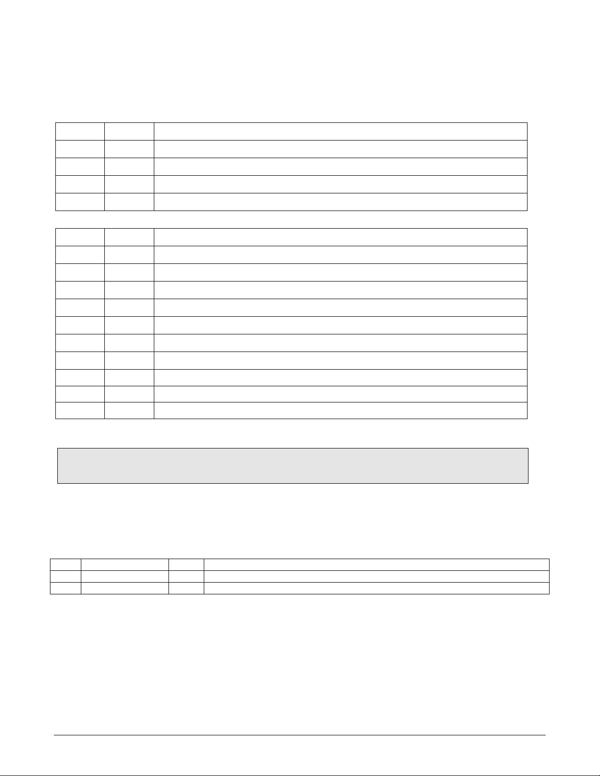
This T101 operation manual, PN 07266, is comprised of multiple documents in PDF
format, as listed below.
Part No. Rev Name/Description
07266 B Model T101 Operation Manual (this manual)
05492 D Menu Trees and Software Documentation (inserted as Appendix A of this manual)
07347
05494 D Repair Questionnaire (inserted as Appendix C of this manual)
03956
04354
04181
04420
04693
04932
04468
06731
05803 B Schem, Gen5 Motherboard
06698 D Schem, LCD Tchscrn Interface
06882 B Schem, LVDS transmitter
1/19/2011
A
D
H
B
E
C
B
B
Spare Parts List (in Appendix B of this manual)
Documents included in Appendix D:
PCA, 03955, Relay Driver
PCA, 04003, Pressure Flow Sensor Board
PCA, 04180, PMT Preamp
PCA, 04120, UV Detector Preamp
PCA, 04692, UV Lamp Driver
PCA, Thermo-Electric Cooler Board
PCA, 04467, Analog Output Isolator
Schem, Auxiliary IO
NOTE
Please read this manual in its entirety before making any attempt to operate the instrument.
REVISION HISTORY
T101 Operation Manual 072660000
REV DATE DCN DESCRIPTION
B 2012 June 08 6845 Administrative updates.
A 2011 February 14 5970 Initial Release
vii
Page 10

07266B DCN6485
This page intentionally left blank.
viii
Page 11

07266B DCN6485
TABLE OF CONTENTS
1. INTRODUCTION ......................................................................................................................... 19
1.1. Features ..............................................................................................................................19
1.2. Options................................................................................................................................20
2. SPECIFICATIONS AND APPROVALS............................................................................................ 23
2.1. Specifications........................................................................................................................23
2.2. Approvals and Certifications....................................................................................................24
2.2.1. Safety ...........................................................................................................................24
2.2.2. EMC .............................................................................................................................. 24
2.2.3. Other Type Certifications.................................................................................................. 24
3. GETTING STARTED..................................................................................................................... 25
3.1. Unpacking and Initial Setup ....................................................................................................25
3.2. Instrument Layout................................................................................................................. 26
3.2.1. Front Panel ....................................................................................................................26
3.2.2. Rear Panel ..................................................................................................................... 30
3.2.3. Internal Chassis Layout....................................................................................................32
3.3. Electrical Connections ............................................................................................................ 33
3.3.1. Analog Inputs (Option 64) Connections .............................................................................. 33
3.3.2. Connecting the Analog Outputs .........................................................................................34
3.3.2.1. Current Loop Analog Outputs (Option 41) Setup............................................................35
3.3.3. Connecting the Status Outputs..........................................................................................36
3.3.4. Connecting the Control Inputs...........................................................................................37
3.3.5. Connecting the Communications Ports................................................................................39
3.3.5.1. Connecting the Serial Ports ........................................................................................39
3.3.5.2. Connecting to a LAN or the Internet ............................................................................ 39
3.3.5.3. Connecting to a Personal Computer (USB Option)..........................................................39
3.3.5.4. Connecting to a Multidrop Network (Option) ................................................................. 39
3.4. Pneumatic Connections .......................................................................................................... 39
3.4.1.1. Connections with Internal Valve Options Installed..........................................................45
3.5. Startup, Functional Checks, and Initial Calibration...................................................................... 50
3.5.1. Startup.......................................................................................................................... 50
3.5.2. Warm-Up....................................................................................................................... 50
3.5.3. Warning Messages .......................................................................................................... 50
3.5.4. Functional Check.............................................................................................................52
3.6. Initial Calibration...................................................................................................................53
3.6.1. Basic Calibration Procedure .............................................................................................. 53
3.6.2. Interferences for H2S Measurements.................................................................................. 56
4. OPERATING INSTRUCTIONS ...................................................................................................... 57
4.1. Overview of Operating Modes .................................................................................................. 57
4.2. Sample Mode........................................................................................................................ 58
4.2.1. Test Functions ................................................................................................................58
4.2.2. Warning Messages .......................................................................................................... 61
4.3. Calibration Mode ................................................................................................................... 62
4.3.1. Calibration Password Security ...........................................................................................62
4.4. Setup Mode ..........................................................................................................................64
4.4.1. Setup – CFG: Viewing the Analyzer’s Configuration Information............................................. 65
4.4.2. Setup – ACAL: Auto Calibration.........................................................................................66
ix
Page 12

TABLE OF CONTENTS Teledyne API – T101 Operation Manual
07266B DCN6485
4.4.3. Setup – DAS: Data Acquisition.......................................................................................... 66
4.4.4. Setup – Range: Analog Output Reporting Range Configuration...............................................66
4.4.4.1. Available Analog Output Signals..................................................................................66
4.4.4.2. Physical Range versus Analog Output Reporting Ranges .................................................67
4.4.4.3. Reporting Range Modes .............................................................................................68
4.4.4.4. Single Range Mode (SNGL) ........................................................................................ 69
4.4.4.5. Independent Range Mode (IND)..................................................................................70
4.4.4.6. Auto Range Mode (AUTO) .......................................................................................... 71
4.4.4.7. Range Units .............................................................................................................72
4.4.4.8. Dilution Ratio ........................................................................................................... 73
4.4.5. Setup – Pass: Password Protection .................................................................................... 74
4.4.6. SETUP – CLK: Setting the Internal Time-of-Day Clock .......................................................... 75
4.5. SETUP – VARS: Using the Internal Variables..............................................................................77
4.5.1. Setting the Gas Measurement Mode...................................................................................80
4.6. SETUP – DIAG: Using the Diagnostics Functions.........................................................................81
4.6.1. Signal I/O ...................................................................................................................... 83
4.6.2. Analog Output Step Test ..................................................................................................84
4.6.3. Analog I/O Configuration.................................................................................................. 85
4.6.3.1. Analog Output Signal Type and Range Span Selection ....................................................87
4.6.3.2. Analog Output Calibration Mode..................................................................................88
4.6.3.3. Manual Analog Output Calibration and Voltage Adjustment .............................................90
4.6.3.4. Analog Output Offset Adjustment................................................................................92
4.6.3.5. Current Loop Output Adjustment.................................................................................92
4.6.3.6. AIN Calibration.........................................................................................................95
4.6.3.7. Analog Inputs (XIN1…XIN8) Option Configuration.......................................................... 96
4.6.4. Optic Test ......................................................................................................................97
4.6.5. Electrical Test.................................................................................................................98
4.6.6. Lamp Calibration.............................................................................................................99
4.6.7. Pressure Calibration ...................................................................................................... 100
4.6.8. Flow Calibration ............................................................................................................ 101
4.6.9. Test Channel Output...................................................................................................... 102
4.7. SETUP – COMM: Setting Up the Analyser’s Communication Ports ................................................ 103
4.7.1. Instrument ID .............................................................................................................. 103
4.7.2. COM Port Default Settings .............................................................................................. 105
4.7.3. RS-232 COM Port Cable Connections................................................................................ 105
4.7.4. RS-485 Configuration ....................................................................................................107
4.7.5. DTE and DCE Communication ......................................................................................... 107
4.7.6. Ethernet Configuration................................................................................................... 107
4.7.6.1. Configuring the Ethernet Interface Using DHCP ........................................................... 107
4.7.6.2. Manually Configuring the Ethernet with Static IP Addresses .......................................... 109
4.7.6.3. Changing the Analyzer’s HOSTNAME.......................................................................... 112
4.7.7. USB Configuration......................................................................................................... 114
4.7.8. Multidrop RS-232 Set Up................................................................................................ 116
4.7.9. MODBUS Set Up ........................................................................................................... 119
4.7.10. COM Port Communication Modes ................................................................................... 121
4.7.11. COM Port Baud Rate .................................................................................................... 123
4.7.12. COM Port Testing ........................................................................................................ 124
4.8. Using the Data Acquisition System (DAS )............................................................................... 124
4.8.1. DAS Structure .............................................................................................................. 125
4.8.1.1. DAS Channels ........................................................................................................ 125
4.8.1.2. DAS Parameters ..................................................................................................... 126
4.8.1.3. DAS Configuration Limits ......................................................................................... 127
4.8.1.4. DAS Triggering Events............................................................................................. 127
4.8.2. Default DAS Channels.................................................................................................... 128
4.8.2.1. Viewing DAS Data and Settings................................................................................. 130
4.8.2.2. Editing DAS Data Channels ......................................................................................131
4.8.2.3. Trigger Events........................................................................................................ 133
4.8.2.4. Editing DAS Parameters........................................................................................... 134
4.8.2.5. Sample Period and Report Period .............................................................................. 135
4.8.2.6. Number of Records ................................................................................................. 137
4.8.2.7. RS-232 Report Function........................................................................................... 139
4.8.2.8. Compact Report ..................................................................................................... 139
x
Page 13

Teledyne API – T101 Operation Manual TABLE OF CONTENTS
07266B DCN6485
4.8.2.9. Starting Date ......................................................................................................... 139
4.8.2.10. Disabling/Enabling Data Channels ........................................................................... 140
4.8.2.11. HOLDOFF Feature .................................................................................................141
4.8.3. Remote DAS Configuration ............................................................................................. 142
5. REMOTE OPERATION................................................................................................................ 143
5.1.1. Remote Operation Using the External Digital I/O................................................................ 143
5.1.1.1. Status Outputs ....................................................................................................... 143
5.1.1.2. Control Inputs........................................................................................................ 145
5.1.2. Remote Operation Using the External Serial I/O.................................................................146
5.1.2.1. Terminal Operating Modes .......................................................................................146
5.1.2.2. Help Commands in Terminal Mode............................................................................. 147
5.1.2.3. Command Syntax ................................................................................................... 148
5.1.2.4. Data Types ............................................................................................................ 148
5.1.2.5. Status Reporting..................................................................................................... 149
5.1.2.6. General Message Format.......................................................................................... 150
5.1.2.7. Remote Access by Modem........................................................................................ 150
5.1.2.8. COM Port Password Security..................................................................................... 153
5.1.2.9. APICOM Remote Control Program.............................................................................. 153
5.1.3. Additional Communications Documentation....................................................................... 154
5.1.4. Using the T101 with a Hessen Protocol Network................................................................. 155
5.1.4.1. General Overview of Hessen Protocol......................................................................... 155
5.1.4.2. Hessen COMM Port Configuration .............................................................................. 155
5.1.4.3. Activating Hessen Protocol ....................................................................................... 156
5.1.4.4. Selecting a Hessen Protocol Type .............................................................................. 157
5.1.4.5. Setting The Hessen Protocol Response Mode............................................................... 157
5.1.4.6. Hessen Protocol Gas ID ........................................................................................... 159
5.1.4.7. Setting Hessen Protocol Status Flags ......................................................................... 160
6. CALIBRATION PROCEDURES.................................................................................................... 163
6.1. Calibration Preparations ....................................................................................................... 163
6.1.1. Required Equipment, Supplies, and Expendables ............................................................... 163
6.1.2. Zero Air....................................................................................................................... 164
6.1.3. Gas Standards.............................................................................................................. 164
6.1.4. Permeation Tubes ......................................................................................................... 164
6.1.5. Calibration Gas Traceability ............................................................................................165
6.1.6. Data Recording Devices ................................................................................................. 165
6.2. Manual Calibration............................................................................................................... 165
6.3. Manual Calibration Checks .................................................................................................... 169
6.4. Manual Calibration with Zero/Span Valves............................................................................... 170
6.5. Manual Calibration with IZS Option ........................................................................................ 173
6.6. Manual Calibration Checks with IZS or Zero/Span Valves .......................................................... 174
6.7. Manual Calibration in INDEPENDENT or AUTO Reporting Range Modes......................................... 177
6.7.1. Calibration With Remote Contact Closures ........................................................................ 177
6.8. Manual Calibration in Multigas Measurement Mode ................................................................... 178
6.9. Automatic Calibration/Checks (AutoCal).................................................................................. 179
6.9.1. Autocal of Instruments in INDEPENDENT or AUTO Reporting Range Modes ............................ 183
6.9.2. Autocal of Instruments in Multigas Measurement Mode ....................................................... 184
6.10. Calibration Quality ............................................................................................................. 185
7. EPA PROTOCOL CALIBRATION ................................................................................................. 187
7.1. Calibration Requirements...................................................................................................... 187
7.1.1. Calibration of Equipment................................................................................................ 187
7.1.2. Data Recording Device................................................................................................... 189
7.1.3. Recommended Standards for Establishing Traceability ........................................................ 189
7.1.4. EPA Calibration Using Permeation Tubes ........................................................................... 189
7.1.5. Calibration Frequency .................................................................................................... 190
7.1.6. Record Keeping ............................................................................................................ 190
7.1.7. Summary of Quality Assurance Checks............................................................................. 191
7.2. Level 1 Calibrations versus Level 2 Checks .............................................................................. 191
7.3. ZERO and SPAN Checks........................................................................................................ 193
7.3.1. Zero/Span Check Procedures .......................................................................................... 193
7.4. Precisions Calibration Procedures and Checks .......................................................................... 193
7.4.1. Precision Calibration ...................................................................................................... 194
7.4.2. Precision Check............................................................................................................. 194
xi
Page 14

TABLE OF CONTENTS Teledyne API – T101 Operation Manual
07266B DCN6485
7.5. Dynamic Multipoint Span Calibration ...................................................................................... 195
7.6. Special Calibration Requirements for Independent Range or Auto Range...................................... 196
7.7. References ......................................................................................................................... 196
8. INSTRUMENT MAINTENANCE................................................................................................... 197
8.1. Maintenance Schedule.......................................................................................................... 197
8.2. Predictive Diagnostics .......................................................................................................... 201
8.3. Maintenance Procedures....................................................................................................... 202
8.3.1. Changing the Sample Particulate Filter ............................................................................. 202
8.3.2. Changing the IZS Permeation Tube.................................................................................. 203
8.3.3. Maintaining the SO2 Scrubber .........................................................................................203
8.3.3.1. Predicting When the SO2 Scrubber Should Be Replaced. ............................................... 203
8.3.3.2. Checking the Function of the SO2 Scrubber................................................................. 204
8.3.3.3. Changing the SO2 Scrubber Material .......................................................................... 204
8.3.4. Changing the External Zero Air Scrubber .......................................................................... 205
8.3.5. Maintaining the H2S SO2 Converter .............................................................................. 206
8.3.5.1. Predicting When the Converter Catalyst Should Be Replaced. ........................................ 206
8.3.5.2. Checking the Efficiency of the H2S SO2 Converter..................................................... 206
8.3.5.3. Changing the H2S SO2 Converter Catalyst Material ................................................... 207
8.3.6. Checking for Light Leaks ................................................................................................ 209
8.3.7. Changing the Critical Flow Orifice .................................................................................... 209
9. TROUBLESHOOTING & SERVICE............................................................................................... 211
9.1. General Troubleshooting....................................................................................................... 211
9.1.1. Fault Diagnosis with Warning Messages............................................................................ 212
9.1.2. Fault Diagnosis with Test Functions.................................................................................. 216
9.1.3. Using the Diagnostic Signal I/O Function .......................................................................... 217
9.1.4. Status LEDs ................................................................................................................. 218
9.1.4.1. Motherboard Status Indicator (Watchdog) .................................................................. 219
9.1.4.2. CPU Status Indicator ............................................................................................... 219
9.1.4.3. Relay Board Status LEDs.......................................................................................... 219
9.2. Gas Flow Problems .............................................................................................................. 220
9.2.1. Zero or Low Sample Flow ............................................................................................... 221
9.2.2. High Flow..................................................................................................................... 221
9.3. Calibration Problems ............................................................................................................ 221
9.3.1. Negative Concentrations ................................................................................................ 221
9.3.2. No Response ................................................................................................................ 222
9.3.3. Unstable Zero and Span................................................................................................. 222
9.3.4. Inability to Span - No SPAN Button.................................................................................. 222
9.3.5. Inability to Zero - No ZERO Button .................................................................................. 223
9.3.6. Non-Linear Response..................................................................................................... 223
9.3.7. Discrepancy Between Analog Output and Display............................................................... 224
9.4. Other Performance Problems................................................................................................. 224
9.4.1. Excessive Noise ............................................................................................................ 224
9.4.2. Slow Response ............................................................................................................. 224
9.4.3. The Analyzer Doesn’t Appear on the LAN or Internet .......................................................... 225
9.5. Subsystem Checkout ........................................................................................................... 225
9.5.1. Detailed Pressure Leak Check ......................................................................................... 225
9.5.2. Performing a Sample Flow Check..................................................................................... 226
9.5.3. AC Power Configuration ................................................................................................. 226
9.5.4. DC Power Supply .......................................................................................................... 227
9.5.5. I2C Bus........................................................................................................................ 228
9.5.6. Touchscreen Interface ................................................................................................... 228
9.5.7. LCD Display Module....................................................................................................... 228
9.5.8. Relay Board ................................................................................................................. 228
9.5.9. Motherboard................................................................................................................. 229
9.5.9.1. A/D functions......................................................................................................... 229
9.5.9.2. Analog Output Voltages ........................................................................................... 229
9.5.9.3. Status Outputs ....................................................................................................... 230
9.5.9.4. Control Inputs........................................................................................................ 230
9.5.10. CPU........................................................................................................................... 230
9.5.11. RS-232 Communication................................................................................................ 231
9.5.11.1. General RS-232 Troubleshooting ............................................................................. 231
9.5.11.2. Modem or Terminal Operation................................................................................. 231
xii
Page 15

Teledyne API – T101 Operation Manual TABLE OF CONTENTS
07266B DCN6485
9.5.12. PMT Sensor ................................................................................................................ 232
9.5.13. PMT Preamplifier Board ................................................................................................ 232
9.5.14. PMT Temperature Control PCA....................................................................................... 232
9.5.15. High Voltage Power Supply ........................................................................................... 233
9.5.16. Pneumatic Sensor Assembly.......................................................................................... 233
9.5.16.1. Sample Pressure................................................................................................... 233
9.5.17. IZS Option ................................................................................................................. 233
9.5.18. Box Temperature ........................................................................................................ 234
9.5.19. PMT Temperature........................................................................................................ 234
9.6. Repair Procedures ............................................................................................................... 234
9.6.1. Disk-on-Module Replacement.......................................................................................... 234
9.6.2. Adjusting the UV Lamp (Peaking the Lamp) ...................................................................... 235
9.6.3. Replacing the UV Lamp .................................................................................................. 237
9.6.4. Factory Cal (PMT Sensor, Hardware Calibration) ................................................................ 238
9.7. Frequently Asked Questions (FAQs)........................................................................................ 240
9.8. Technical Assistance ............................................................................................................ 241
10. PRINCIPLES OF OPERATION.................................................................................................. 243
10.1. Measurement Principle ....................................................................................................... 243
10.1.1. H2S Conversion ........................................................................................................... 243
10.1.2. SO2 Ultraviolet Fluorescence ......................................................................................... 244
10.2. The UV Light Path.............................................................................................................. 247
10.2.1. UV Source Lamp ......................................................................................................... 247
10.2.2. The Reference Detector................................................................................................ 248
10.2.3. The PMT..................................................................................................................... 248
10.2.4. Optical Filters ............................................................................................................. 249
10.2.4.1. UV Source Optical Filter ......................................................................................... 249
10.2.4.2. PMT Optical Filter.................................................................................................. 249
10.2.5. Optical Lenses ............................................................................................................ 250
10.2.6. Measurement Interferences .......................................................................................... 251
10.2.6.1. Direct Interference................................................................................................ 251
10.2.6.2. UV Absorption by Ozone ........................................................................................ 252
10.2.6.3. Dilution ............................................................................................................... 252
10.2.6.4. Third Body Quenching............................................................................................252
10.2.6.5. Light Pollution ...................................................................................................... 252
10.3. Pneumatic Operation.......................................................................................................... 253
10.3.1. Sample Gas Flow......................................................................................................... 254
10.3.2. Multigas Measurement & H2S SO2 Switching Valve........................................................ 255
10.3.3. Flow Rate Control........................................................................................................ 255
10.3.3.1. Critical Flow Orifice ............................................................................................... 255
10.3.4. Sample Particulate Filter............................................................................................... 256
10.3.5. Hydrocarbon Scrubber (Kicker) ..................................................................................... 257
10.3.6. SO2 Scrubber.............................................................................................................. 257
10.3.7. Pneumatic Sensors ...................................................................................................... 258
10.3.7.1. Sample Pressure Sensor ........................................................................................ 258
10.3.7.2. Sample Flow Sensor.............................................................................................. 258
10.4. Electronic Operation........................................................................................................... 259
10.4.1. CPU........................................................................................................................... 261
10.4.1.1. Disk On Module (DOM) .......................................................................................... 261
10.4.1.2. Flash Chip............................................................................................................ 261
10.4.2. Sensor Module & Sample chamber ................................................................................. 262
10.4.3. Sample Chamber Heating Circuit ................................................................................... 262
10.4.4. Photo Multiplier Tube (PMT) .......................................................................................... 263
10.4.5. PMT Cooling System .................................................................................................... 264
10.4.5.1. Thermoelectric Cooler (TEC) ................................................................................... 264
10.4.5.2. TEC Control Board................................................................................................. 265
10.4.6. PMT Preamplifier ......................................................................................................... 265
10.4.7. Pneumatic Sensor Board............................................................................................... 267
10.4.8. Relay Board................................................................................................................ 267
10.4.8.1. Heater Control...................................................................................................... 267
10.4.8.2. Valve Control ....................................................................................................... 267
10.4.9. Status LEDs & Watch Dog Circuitry ................................................................................ 268
10.4.10. Motherboard ............................................................................................................. 269
xiii
Page 16

TABLE OF CONTENTS Teledyne API – T101 Operation Manual
07266B DCN6485
10.4.10.1. A to D Conversion ............................................................................................... 269
10.4.10.2. Sensor Inputs..................................................................................................... 269
10.4.10.3. Thermistor Interface............................................................................................ 270
10.4.11. Analog Outputs ......................................................................................................... 270
10.4.12. External Digital I/O.................................................................................................... 271
10.4.13. I2C Data Bus............................................................................................................. 271
10.4.14. Power up Circuit ........................................................................................................ 271
10.5. Power Supply/ Circuit Breaker ............................................................................................. 271
10.6. Front Panel/Display Interface .............................................................................................. 273
10.6.1. LVDS Transmitter Board............................................................................................... 273
10.6.2. Front Panel Interface PCA ............................................................................................. 273
10.7. Software Operation............................................................................................................ 274
10.7.1. Adaptive Filter ............................................................................................................ 274
10.7.2. Calibration - Slope and Offset........................................................................................ 275
10.7.3. Temperature and Pressure Compensation (TPC) Feature ................................................... 276
10.7.4. Internal Data Acquisition System (DAS )......................................................................... 276
11. A PRIMER ON ELECTRO-STATIC DISCHARGE.......................................................................... 277
11.1. How Static Charges are Created........................................................................................... 277
11.2. How Electro-Static Charges Cause Damage ........................................................................... 278
11.3. Common Myths About ESD Damage ..................................................................................... 279
11.4. Basic Principles of Static Control .......................................................................................... 280
11.4.1. General Rules ............................................................................................................. 280
11.4.2. Basic anti-ESD Procedures for Analyzer Repair and Maintenance ........................................ 282
11.4.2.1. Working at the Instrument Rack.............................................................................. 282
11.4.2.2. Working at an Anti-ESD Work Bench........................................................................ 282
11.4.2.3. Transferring Components from Rack to Bench and Back.............................................. 283
11.4.2.4. Opening Shipments from Teledyne API..................................................................... 283
11.4.2.5. Packing Components for Return to Teledyne API........................................................ 284
LIST OF APPENDICES
APPENDIX A - VERSION SPECIFIC SOFTWARE DOCUMENTATION
APPENDIX B - T101 SPARE PARTS LIST
APPENDIX C - REPAIR QUESTIONNAIRE - T101
APPENDIX D - ELECTRONIC SCHEMATICS
xiv
Page 17

Teledyne API – T101 Operation Manual TABLE OF CONTENTS
07266B DCN6485
LIST OF FIGURES
Figure 3-1. Front Panel Layout ........................................................................................... 27
Figure 3-2. Display Screen and Touch Control ...................................................................... 27
Figure 3-3. Display/Touch Control Screen Mapped to Menu Charts.......................................... 29
Figure 3-4. Rear Panel Layout............................................................................................ 30
Figure 3-5. Internal Chassis Layout..................................................................................... 32
Figure 3-6. Analog In Connector......................................................................................... 33
Figure 3-7. Analog Output Connector .................................................................................. 34
Figure 3-8. Current Loop Option Installed on the Motherboard................................................ 35
Figure 3-9. Status Output Connector................................................................................... 36
Figure 3-10. Control Input Connector.................................................................................. 38
Figure 3-11. Pneumatic Connections, Basic Configuration Using Gas Dilution Calibrator .............. 40
Figure 3-12. Pneumatic Connections, Basic Configuration Using Bottled Span Gas ..................... 41
Figure 3-13. Pneumatic Diagram of the T101 Standard Configuration ...................................... 42
Figure 3-14. Basic Pneumatic Connections for Units with Valve Options.................................... 45
Figure 3-15. Pneumatic Diagram of the T101 With Z/S Option Installed ................................... 46
Figure 3-16. Pneumatic Diagram of the T101 with IZS Options Installed................................... 49
Figure 4-1. Viewing T101 TEST Functions ............................................................................ 60
Figure 4-2. Viewing and Clearing T101 WARNING Messages ................................................... 62
Figure 4-3. Analog Output Connectors Defined ..................................................................... 66
Figure 4-4. Setup for Calibrating Analog Outputs .................................................................. 91
Figure 4-5. Setup for Calibrating Current Outputs ................................................................. 93
Figure 4-6. DIAG – Analog Inputs (Option) Configuration Menu............................................... 96
Figure 4-7. Rear Panel Connector Pin-Outs for RS-232 Mode ................................................ 105
Figure 4-8. CPU Connector Pin-Outs for RS-232 Mode ......................................................... 106
Figure 4-9. Jumper and Cables for Multidrop Mode.............................................................. 117
Figure 4-10.Multidrop PCA Host/Analyzer Interconnect Diagram............................................ 118
Figure 4-11. Default DAS Channels Setup.......................................................................... 129
Figure 4-12. APICOM User Interface for Configuring the DAS ................................................ 142
Figure 5-1. Status Output Connector................................................................................. 144
Figure 5-2. Control Inputs with Local 5 V Power Supply ....................................................... 146
Figure 5-3.Control Inputs with External 5 V Power Supply .................................................... 146
Figure 5-4. APICOM Remote Control Program Interface ....................................................... 154
Figure 6-1. Setup for Manual Calibration without Z/S Valve or IZS Option .............................. 166
Figure 6-2. Setup for Manual Calibration with Z/S Valve Option Installed................................ 170
Figure 6-3. Setup for Manual Calibration Check with Z/S Valve or IZS Option.......................... 175
Figure 6-4. Typical Setup for Manual Calibratio in Multigas Measurement Mode ....................... 178
Figure 8-1. Sample Particulate Filter Assembly ................................................................... 202
Figure 8-2. Charcoal Canister Assembly............................................................................. 205
Figure 8-3. H2S - SO2 Converter Assembly........................................................................ 208
Figure 8-4. Critical Flow Orifice Assembly ......................................................................... 210
Figure 9-1. Viewing and Clearing Warning Messages ........................................................... 214
Figure 9-2. Example of Signal I/O Function ........................................................................ 218
Figure 9-3. CPU Status Indicator ...................................................................................... 219
Figure 9-4. Shutter Assembly........................................................................................... 236
Figure 9-5. Location of UV Reference Detector Potentiometer ............................................... 237
Figure 9-6. Pre-Amplifier Board Layout.............................................................................. 239
Figure 10-1. UV Absorption.............................................................................................. 245
Figure 10-2. UV Light Path .............................................................................................. 247
Figure 10-3. Source UV Lamp Construction ........................................................................ 248
Figure 10-4. Excitation Lamp UV Spectrum Before/After Filtration ......................................... 249
Figure 10-5. PMT Optical Filter Bandwidth.......................................................................... 250
Figure 10-6. Effects of Focusing Source UV in Sample Chamber ............................................ 250
Figure 10-7. T101 Gas Flow and Location of Critical Flow Orifice ........................................... 254
xv
Page 18

TABLE OF CONTENTS Teledyne API – T101 Operation Manual
07266B DCN6485
Figure 10-8. Typical Flow Control Assembly with Critical Flow Orifice ..................................... 256
Figure 10-9. T101 Hydrocarbon Scrubber (Kicker) .............................................................. 257
Figure 10-10. T101 Electronic Block Diagram ..................................................................... 259
Figure 10-11. T101 CPU Board ......................................................................................... 261
Figure 10-12. T101 Sample Chamber................................................................................ 262
Figure 10-13. PMT Assembly............................................................................................ 263
Figure 10-14. Basic PMT Design ....................................................................................... 264
Figure 10-15. PMT Cooling System ................................................................................... 265
Figure 10-16. PMT Preamp Block Diagram ......................................................................... 266
Figure 10-17. Relay Board Status LED Locations................................................................. 268
Figure 10-18. Power Distribution Block Diagram ................................................................. 272
Figure 10-19. Front Panel and Display Interface Block Diagram............................................. 273
Figure 10-20. Basic Software Operation............................................................................. 274
Figure 11-1. Triboelectric Charging ................................................................................... 277
Figure 11-2. Basic anti-ESD Work Station .......................................................................... 280
LIST OF TABLES
Table 1-1. Analyzer Options............................................................................................... 20
Table 2-1. Model T101 Basic Unit Specifications.................................................................... 23
Table 3-1. Display Screen and Touch Control Description ....................................................... 28
Table 3-2. Rear Panel Description....................................................................................... 31
Table 3-3. Analog Input Pin Assignments............................................................................. 34
Table 3-4. Analog Output Pin Assignmentss ......................................................................... 35
Table 3-5. Status Output Signals........................................................................................ 37
Table 3-6. Control Input Signals......................................................................................... 38
Table 3-7. Inlet / Outlet Connector Descriptions ................................................................... 40
Table 3-8. H2S – SO2 Switching Valve Operating States ......................................................... 42
Table 3-9. NIST-SRM's Available for Traceability of H2S & SO2 Calibration Gases ....................... 44
Table 3-10. Zero/Span Valve Operating States ..................................................................... 46
Table 3-11. IZS Valve Operating States............................................................................... 49
Table 3-12. Possible Warning Messages at Start-Up .............................................................. 51
Table 4-1. Analyzer Operating Modes .................................................................................. 57
Table 4-2. Test Functions Defined....................................................................................... 59
Table 4-3. List of Warning Messages ................................................................................... 61
Table 4-4. Primary Setup Mode Features and Functions ......................................................... 64
Table 4-5. Secondary Setup Mode Features and Functions ..................................................... 64
Table 4-6. Password Levels............................................................................................... 74
Table 4-7. Variable Names (VARS)...................................................................................... 77
Table 4-8. T101 Diagnostic (DIAG) Functions ....................................................................... 81
Table 4-9. DIAG - Analog I/O Functions............................................................................... 85
Table 4-10. Analog Output Voltage Ranges .......................................................................... 85
Table 4-11. Analog Output Current Loop Range .................................................................... 86
Table 4-12. Analog Output Pin Assignments ......................................................................... 86
Table 4-13. Voltage Tolerances for Analog Output Calibration ................................................. 90
xvi
Page 19

Teledyne API – T101 Operation Manual TABLE OF CONTENTS
07266B DCN6485
Table 4-14. Current Loop Output Calibration with Resistor ..................................................... 94
Table 4-15. Test Parameters Available for Analog Output A4 ................................................ 102
Table 4-16. Ethernet Status Indicators .............................................................................. 107
Table 4-17. LAN/Internet Default Configuration Properties ................................................... 109
Table 4-18. Internet Configuration Touchscreen Button Functions ......................................... 113
Table 4-19. COMM Port Communication Modes ................................................................... 121
Table 4-20. Front Panel LED Status Indicators for DAS ........................................................ 125
Table 4-21. DAS Data Channel Properties .......................................................................... 126
Table 4-22. DAS Data Parameter Functions........................................................................ 127
Table 5-1. Status Output Pin Assignments ......................................................................... 145
Table 5-2. Control Input Pin Assignments .......................................................................... 145
Table 5-3. Terminal Mode Software Commands .................................................................. 147
Table 5-4. Command Types ............................................................................................. 148
Table 5-5. Serial Interface Documents .............................................................................. 154
Table 5-6. Hessen RS-232 Communication Parameters........................................................ 155
Table 5-7. T101 Hessen Protocol Response Modes............................................................... 157
Table 5-8. Default Hessen Status Bit Assignments .............................................................. 160
Table 6-1. NIST-SRM's Available for Traceability of H2S and SO2 Calibration Gases ................. 165
Table 6-2. AutoCal Modes................................................................................................ 179
Table 6-3. AutoCal Attribute Setup Parameters................................................................... 180
Table 6-4. Example Auto-Cal Sequence ............................................................................. 181
Table 6-5. Example Auto-Cal Sequence ............................................................................. 185
Table 7-1. Activity Matrix for Calibration Equipment & Supplies............................................. 188
Table 7-2. Activity Matrix for Calibration Procedure ............................................................. 189
Table 7-3. Activity Matrix ................................................................................................ 191
Table 7-4. Definition of Level 1 and Level 2 Zero and Span Checks........................................ 192
Table 8-1 T101 Preventive Maintenance Schedule ............................................................... 199
Table 8-2 Predictive Uses for Test Functions....................................................................... 201
Table 9-1. Warning Messages - Indicated Failures............................................................... 214
Table 9-2. Test Functions - Possible Causes for Out-Of-Range Values .................................... 216
Table 9-3. Relay Board Status LEDs.................................................................................. 220
Table 9-4. DC Power Test Point and Wiring Color Code ........................................................ 227
Table 9-5. DC Power Supply Acceptable Levels ................................................................... 227
Table 9-6. Relay Board Control Devices ............................................................................. 229
Table 9-7. Analog Output Test Function - Nominal Values .................................................... 229
Table 9-8. Status Outputs Check Pin Out ........................................................................... 230
Table 9-9. Example of UV Lamp Power Supply Outputs........................................................ 237
xvii
Page 20

TABLE OF CONTENTS Teledyne API – T101 Operation Manual
07266B DCN6485
This page intentionally left blank.
xviii
Page 21

07266B DCN6485
1. INTRODUCTION
The Model T101 UV Fluorescence H2S Analyzer measures hydrogen sulfide in levels
commonly required for Ambient Air monitoring. The analyzer converts sulfur gases to
sulfur dioxide and measures the SO
1.1. FEATURES
Some features of the T101 include:
LCD Graphical User Interface with capacitive touch screen
concentrations using fluorescence technology.
2
Microprocessor controlled for versatility
Multi-tasking software allows viewing of test variables during operation
Bi-directional USB, RS-232, and 100BaseT Ethernet ports for remote
operation (optional RS-485)
Front panel USB ports for peripheral devices
Auto ranging, dual range and remote range selection
Built in self checks and diagnostic capabilities
Digital status outputs provide instrument condition
Auto Zero System
Adaptive signal filtering optimizes response time
Temperature & pressure compensation
Optional Calibration valves or permeation oven
User friendly operation and set up
Internal Zero Span
Internal Datalogger
Critical Orifices provide flow stability
19
Page 22
Introduction Teledyne API – T101 Operation Manual
07266B DCN6485
1.2. OPTIONS
The options available for your analyzer are presented in Table 1-1 with name, option
number, a description and/or comments, and if applicable, cross-references to technical
details in this manual, such as setup and calibration. To order these options or to learn
more about them, please contact the Sales department of Teledyne - Advanced Pollution
Instruments at:
TOLL-FREE: 800-324-5190
TEL: +1 858-657-9800
FAX: +1 858-657-9816
E-MAIL: apisales@teledyne.com
WEB SITE: http://www.teledyne-api.com/
Table 1-1. Analyzer Options
Option
Pumps
Rack Mount
Kits
Carrying Strap/Handle Side-mounted strap for hand-carrying analyzer
29
Option
Number
Pumps meet all typical AC power supply standards while exhibiting
same pneumatic performance.
10A External Pump 100V - 120V @ 60 Hz
10B External Pump 220V - 240V @ 50 Hz
10C External Pump 220V - 240V @ 60 Hz
10D External Pump 100V – 12V @ 50 Hz
10E External Pump 100V @ 60 Hz
11A Pumpless (if one is standard either internal or external)
13 High Voltage Internal Pump 240V @ 50Hz
20A Rack mount brackets with 26 in. chassis slides
20B Rack mount brackets with 24 in. chassis slides
21 Rack mount brackets only (compatible with carrying strap, Option 29)
23 Rack mount for external pump pack (no slides)
Options for mounting the analyzer in standard 19” racks
Extends from “flat” position to accommodate hand for carrying.
Recesses to 9mm (3/8”) dimension for storage.
Can be used with rack mount brackets, Option 21.
Cannot be used with rack mount slides.
Description/Notes
20
CAUTION
GENERAL SAFETY HAZARD
A FULLY LOADED T101 WITH VALVE OPTIONS WEIGHS >20 KG (45
POUNDS).
To avoid personal injury we recommend that two persons lift and carry the
analyzer. Disconnect all cables and tubing from the analyzer before moving it.
Page 23
Teledyne API – T101 Operation Manual Introduction
07266B DCN6485
Option
Analog Inputs
64 Also can be used for logging these signals in the analyzer’s internal DAS
Current Loop Analog
Outputs
41
Parts Kits
NO Optical Filter Recommended for High NOX backgrounds.
47B Required for EN Certification.
Calibration Valves
Option
Number
Used for connecting external voltage signals from other instrumentation (such
as meteorological instruments).
Adds isolated, voltage-to-current conversion circuitry to the
analyzer’s analog outputs.
Isolated 0-20 or 4-20 mA current output (up to three can be retrofitted if not
installed at the factory)
42A
43
45 Spare Parts Kit includes spares parts for one unit.
50A Ambient Zero and Ambient Span
Expendables Kit with IZS includes the items needed to refurbish the
internal zero air scrubber (IZS) that is included.
Used to control the flow of calibration gases generated from external
sources, rather than manually switching the rear panel pneumatic
connections.
Description/Notes
50G Zero Scrubber and Internal Span Source (IZS)
H2 S Permeation Tubes
(uncertified) 52A 106 ng/min .08 -.12 ppm 0.76 lpm (nominal) ± 25%
(certified) 52E 76 ng/min .04 - .06 ppm 0.76 lpm ± 5%
Communication Cables
Type Description
60A RS-232
60B RS-232
60C Ethernet
60D USB
Concentration Alarm
Relay
61
Replacement tubes for the IZS option; identical size/shape; different
effusion rates.
Effusion Rate
(@ 50°C)
For remote serial, network and Internet communication with the
analyzer.
Shielded, straight-through DB-9F to DB-25M cable, about 1.8 m
long. Used to interface with older computers or code activated
switches with DB-25 serial connectors.
Shielded, straight-through DB-9F to DB-9F cable of about 1.8 m
length.
Patch cable, 2 meters long, used for Internet and LAN
communications.
Cable for direct connection between instrument (rear panel USB
port) and personal computer.
Issues warning when gas concentration exceeds limits set by user.
Four (4) “dry contact” relays on the rear panel of the instrument. This relay
option is different from and in addition to the “Contact Closures” that come
standard on all TAPI instruments.
Approximate
Concentration
Specified Flow Rate (of indicated perm
tube rate)
21
Page 24
Introduction Teledyne API – T101 Operation Manual
07266B DCN6485
Option
RS-232 Multidrop
62
Special Features Built in features, software activated
N/A
N/A
N/A
Option
Number
Description/Notes
Enables communications between host computer and up to eight
analyzers.
Multidrop card seated on the analyzer’s CPU card.
Each instrument in the multidrop network requires this card and a
communications cable (Option 60B).
Maintenance Mode Switch, located inside the instrument, places the
analyzer in maintenance mode where it can continue sampling, yet ignore
calibration, diagnostic, and reset instrument commands. This feature is of
particular use for instruments connected to Multidrop or Hessen protocol
networks.
Call Technical Support for activation.
Second Language Switch activates an alternate set of display messages in
a language other than the instrument’s default language.
Call Technical Support for a specially programmed Disk on Module containing the
second language.
Dilution Ratio Option allows the user to compensate for diluted sample gas,
such as in continuous emission monitoring (CEM) where the quality of gas in a
smoke stack is being tested and the sampling method used to remove the gas
from the stack dilutes the gas.
Call Technical Support for activation.
22
Page 25

07266B DCN6485
2. SPECIFICATIONS AND APPROVALS
2.1. SPECIFICATIONS
Table 2-1. Model T101 Basic Unit Specifications
PARAMETER
Ranges H2S: Min 0-50 ppb Full scale; Max 0-10 ppm Full scale
SO
: Up to 0-20 ppm Full scale
2
(selectable, independent ranges and auto ranging supported)
Measurement Units ppb, ppm, µg/m3, mg/m3 (selectable)
Zero Noise1 <0.2 ppb (RMS)
Span Noise1 <0.5% of reading (RMS) above 50 ppb
Lower Detectable Limit2 0.4 ppb
Zero Drift (24 hours) <0.5 ppb
Span Drift (24 hours) <0.5% of full scale
Lag Time 20 seconds
Rise/Fall Time1 <120 seconds to 95%
Linearity 1% of full scale
Precision 0.5% of reading above 50 ppb
Sample Flow Rate
Temperature Coefficient < 0.1% per oC
Voltage Coefficient < 0.05% per V
Temperature Range 5-40oC
Humidity Range 0 - 95% RH, non-condensing
Dimensions H x W x D 7" x 17" x 23.5" (178 mm x 432 mm x 597 mm)
Weight, Analyzer
(Basic Configuration)
AC Power 100V-120V, 60 Hz (202W); 220V-240V, 50 Hz (200W)
Analog Output Ranges 10 V, 5V, 1V, 0.1V (selectable)
Analog Output Resolution 1 part in 4096 of selected full-scale voltage
Recorder Offset
Environmental Installation category (over-voltage category) II; Pollution degree 2
650 cm
41 lbs (18.3 kg)
45 lbs (20.5 kg) w/internal pump
±10%
3
/min ±10%
DESCRIPTION
23
Page 26

Specifications and Approvals Teledyne API – T101 Operation Manual
07266B DCN6485
PARAMETER
Standard I/O 1 Ethernet: 10/100Base-T
Optional I/O
For indoor use at altitudes ≤ 2000m only
2 RS-232 (300 – 115,200 baud)
2 USB device ports
8 opto-isolated digital status outputs
6 opto-isolated digital control inputs
4 analog outputs
1 USB com port
1 RS485
8 analog inputs (0-10V, 12-bit)
4 digital alarm outputs
Multidrop RS232
3 4-20mA current outputs
DESCRIPTION
2.2. APPROVALS AND CERTIFICATIONS
The Teledyne API Model T101 analyzer was tested and certified for Safety and
Electromagnetic Compatibility (EMC). This section presents the compliance statements
for those requirements and directives.
2.2.1. SAFETY
IEC 61010-1:2001, Safety requirements for electrical equipment for
measurement, control, and laboratory use.
CE: 2006/95/EC, Low-Voltage Directive
North American:
cNEMKO (Canada): CAN/CSA-C22.2 No. 61010-1-04
NEMKO-CCL (US): UL No. 61010-1 (2nd Edition)
2.2.2. EMC
EN 61326-1 (IEC 61326-1), Class A Emissions/Industrial Immunity
EN 55011 (CISPR 11), Group 1, Class A Emissions
FCC 47 CFR Part 15B, Class A Emissions
CE: 2004/108/EC, Electromagnetic Compatibility Directive
2.2.3. OTHER TYPE CERTIFICATIONS
For additional certifications, please contact Technical Support:
Toll-free Phone:
Phone:
Fax:
Email:
800-324-5190
858-657-9800
858-657-9816
Sda_techsupport@teledyne.com
24
Page 27
07266B DCN6485
3. GETTING STARTED
3.1. UNPACKING AND INITIAL SETUP
CAUTION
To avoid personal injury, always use two persons to lift and carry the Model T101.
CAUTION – Avoid Warranty Invalidation
Printed circuit assemblies (PCAs) are sensitive to electro-static discharges too small
to be felt by the human nervous system. Damage resulting from failure to use ESD
protection when working with electronic assemblies will void the instrument warranty.
See A Primer on Electro-Static Discharge in this manual for more information on preventing
ESD damage.
Remove dust plugs prior to operating instrument. It is recommended that you store shipping
containers/materials, including shipping screws and dust plugs for the pneumatic ports, for future use
if/when the instrument should be returned to the factory for repair and/or calibration service. See
Warranty section in this manual and shipping procedures on our Website at
http://www.teledyne-api.com under Customer Support > Return Authorization.
1. Inspect the received packages for external shipping damage. If damaged,
please advise the shipper first, then Teledyne API.
2. Included with your analyzer is a printed record (Form number 04551) of
the final performance characterization performed on your instrument at
the factory. This record is an important quality assurance and calibration
record for this instrument. It should be placed in the quality records file
for this instrument.
NO
TE
25
3. Carefully remove the top cover of the analyzer and check for internal
shipping damage.
Remove the set screw located in the top, center of the rear panel
Remove the screws fastening the top cover to the unit (four per side).
Lift the cover straight up.
Page 28

Getting Started Teledyne API – T101 Operation Manual
07266B DCN6485
4. Inspect the interior of the instrument to make sure all circuit boards and
other components are in good shape and properly seated.
5. Check the connectors of the various internal wiring harnesses and
pneumatic hoses to make sure they are firmly and properly seated.
6. Verify that all of the optional hardware ordered with the unit has been
installed. These are checked on the paperwork (Form 04551)
accompanying the analyzer.
7. VENTILATION CLEARANCE: Whether the analyzer is set up on a bench
or installed into an instrument rack, be sure to leave sufficient ventilation
clearance.
AREA MINIMUM REQUIRED CLEARANCE
Back of the instrument 10 cm / 4 inches
Sides of the instrument 2.5 cm / 1 inch
Above and below the instrument. 2.5 cm / 1 inch
Various rack mount kits are available for this analyzer.
3.2. INSTRUMENT LAYOUT
Instrument layout includes front panel and display, rear panel connectors, and internal
chassis layout.
3.2.1. FRONT PANEL
Figure 3-1 shows the analyzer’s front panel layout, followed by a close-up of the display
screen in Figure 3-2, which is described in Table 3-1. The two USB ports on the front
panel are provided for the connection of peripheral devices:
• plug-in mouse (not included) to be used as an alternative to the
touchscreen interface
• thumb drive (not included) to download updates to instruction software
(contact TAPI Technical Support for information).
26
Page 29
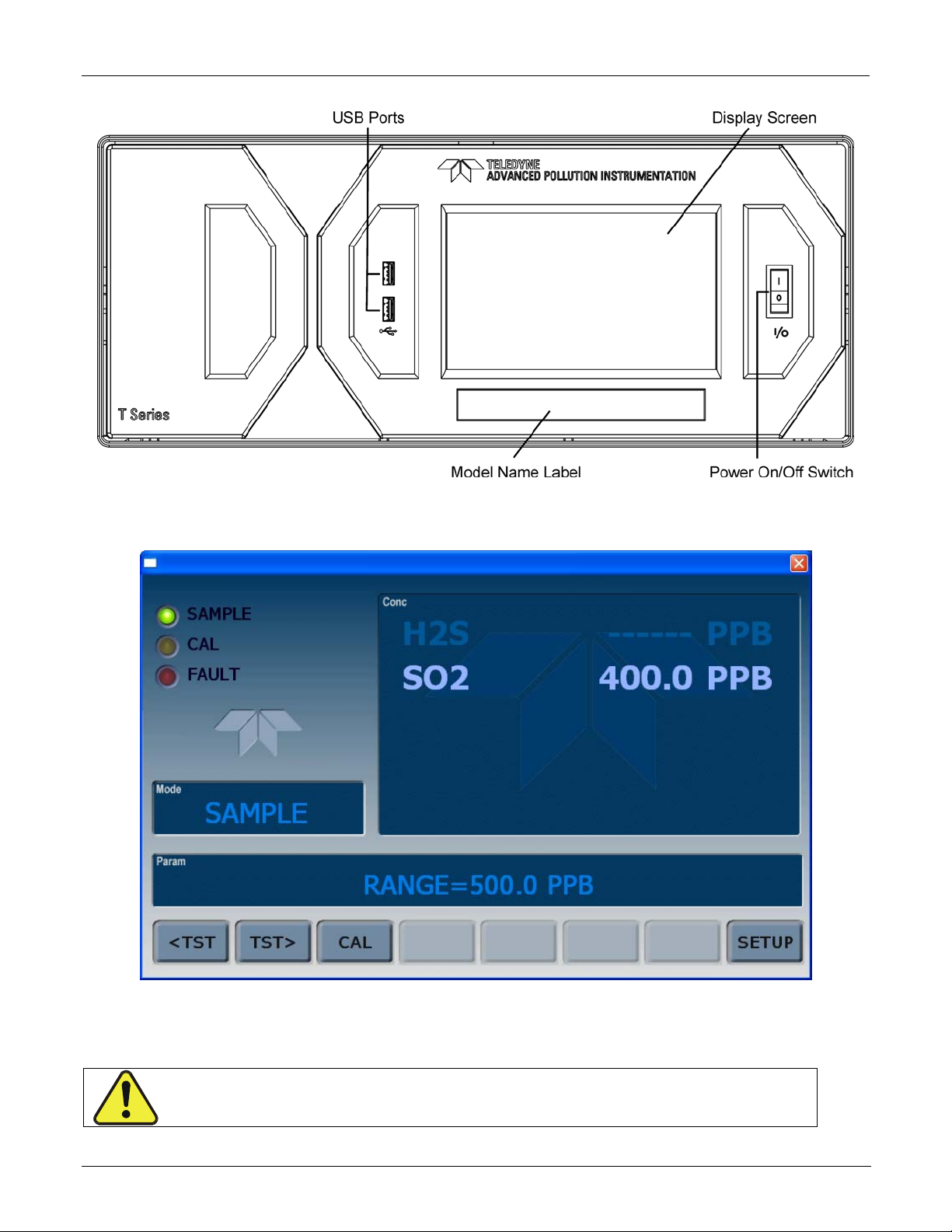
Teledyne API – T101 Operation Manual Getting Started
07266B DCN6485
Figure 3-1. Front Panel Layout
27
Figure 3-2. Display Screen and Touch Control
CAUTION – Avoid Damaging Touchscreen
Do not use hard-surfaced instruments such as pens to operat e the
touchscreen.
Page 30
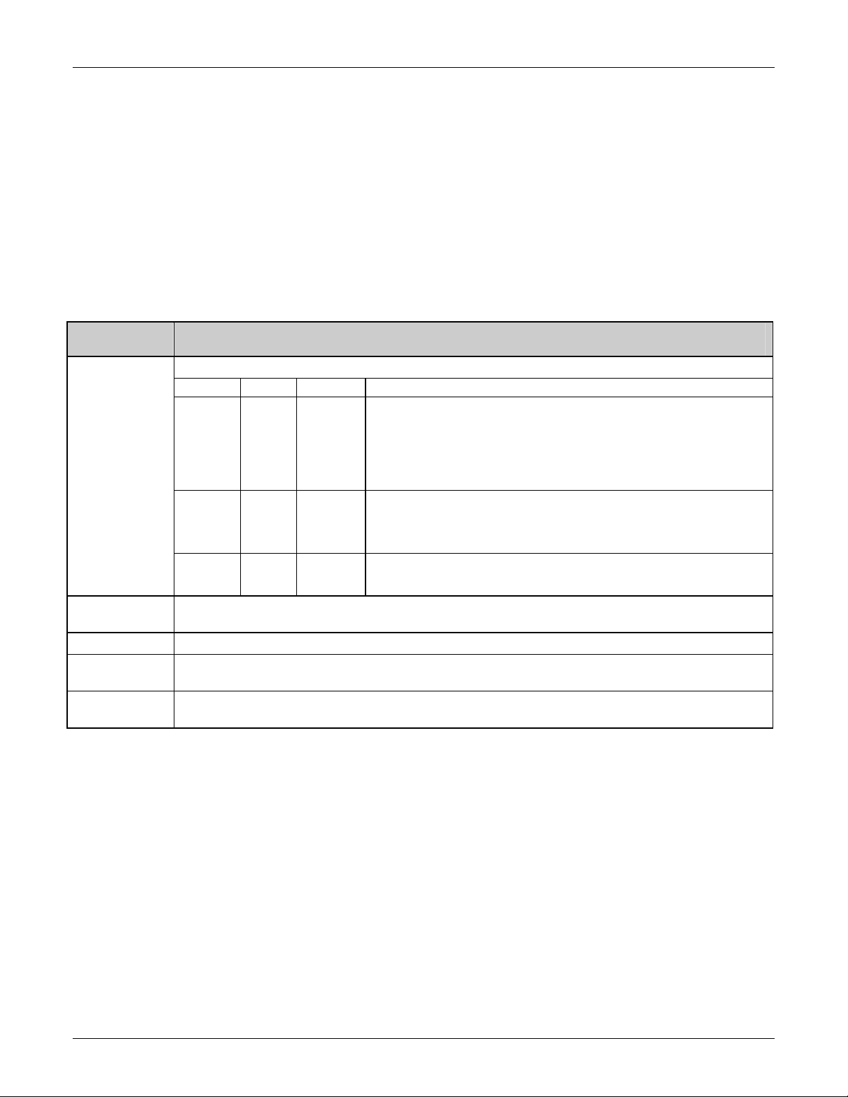
Getting Started Teledyne API – T101 Operation Manual
07266B DCN6485
The front panel liquid crystal display screen includes touch control. Upon analyzer startup, the screen shows a splash screen and other initialization indicators before the main
display appears, similar to Figure 3-2 above (may or may not display a Fault alarm). The
LEDs on the display scree
n indicate the Sample, Calibration and Fault states; also on the
screen is the gas concentration field (Conc), which displays real-time readouts for the
primary gas and for the secondary gas if installed. The display screen also shows what
mode the analyzer is currently in, as well as messages and data (Param). Along the
bottom of the screen is a row of touch control buttons; only those that are currently
applicable will have a label. Table 3-1 provides detailed information for each component
of the screen.
Table 3-1. Display Screen and Touch Control Description
Field Description/Function
Status
Conc
Mode Displays the name of the analyzer’s current operating mode
Param
Control
Buttons
LEDs indicating the states of Sample, Calibration and Fault, as follows:
Name Color State Definition
Off
On
SAMPLE Green
CAL Yellow
FAULT Red
Displays the actual concentration of the sample gas currently being measured by the
analyzer in the currently selected units of measure
Displays a variety of informational messages such as warning messages, operational data,
test function values and response messages during interactive tasks.
Displays dynamic, context sensitive labels on each button, which is blank when inactive until
applicable.
Blinking
Off
On
Blinking
Off
Blinking
Unit is not operating in sample mode, DAS is disabled.
Sample Mode active; Front Panel Display being updated; DAS
data being stored.
Unit is operating in sample mode, front panel display being
updated, DAS hold-off mode is ON, DAS disabled
Auto Cal disabled
Auto Cal enabled
Unit is in calibration mode
No warnings exist
Warnings exist
Figure 3-3 shows how the front panel display is m
apped to the menu charts illustrated in
this manual. The Mode, Param (parameters), and Conc (gas concentration) fields in the
display screen are represented across the top row of each menu chart. The eight touch
control buttons along the bottom of the display screen are represented in the bottom row
of each menu chart.
28
Page 31

Teledyne API – T101 Operation Manual Getting Started
07266B DCN6485
Figure 3-3. Display/Touch Control Screen Mapped to Menu Charts
29
Page 32

Getting Started Teledyne API – T101 Operation Manual
07266B DCN6485
3.2.2. REAR PANEL
Figure 3-4. Rear Panel Layout
30
Page 33

Teledyne API – T101 Operation Manual Getting Started
07266B DCN6485
Table 3-2. Rear Panel Description
Component Function
cooling fan
power
connect
SAMPLE
EXHAUST
SPAN 1
SPAN2/VENT
ZERO AIR
RX TX
COM 2
RS-232
DCE DTE
STATUS
ANALOG OUT
CONTROL IN
ALARM
Information Label
ETHERNET
ANALOG IN
USB
Pulls ambient air into chassis through side vents and exhausts through
rear.
Connector for three-prong cord to apply AC power to the analyzer.
AC
CAUTION! The cord’s power specifications (specs) MUST comply
with the power specs on the analyzer’s rear panel Model number
label
or
Connect a gas line from the source of sample gas here.
Calibration gases are also inlet here on units without zero/span/shutoff
valve options installed.
Connect an exhaust gas line of not more than 10 meters long here that
leads outside the shelter or immediate area surrounding the instrument.
On units with zero/span/shutoff valve options installed, connect a gas line
to the source of calibrated span gas here.
Used as a second cal gas input line when instrument is configured with
zero/span valves and a dual gas option, or as a cal gas vent line when
instrument is configured with a pressurized span option
details).
Internal Zero Air: On units with zero/span/shutoff valve options installed
but no internal zero air scrubber attach a gas line to the source of zero air
here.
LEDs indicate receive (RX) and transmit (TX) activity on the when blinking.
Serial communications port for RS-232 or RS-485.
Serial communications port for RS-232 only.
Switch to select either data terminal equipment or data communication
equipment during RS-232 communication.
For outputs to devices such as Programmable Logic Controllers (PLCs).
For voltage or current loop outputs to a strip chart recorder and/or a data
logger.
For remotely activating the zero and span calibration modes.
Option for concentration alarms and system warnings.
Identifies the analyzer model number and provides power specifications
Connector for network or Internet remote communication, using Ethernet
cable
Option for external voltage signals from other instrumentation and for
logging these signals
Connector for direct connection to personal computer, using USB cable.
(Call factory for
31
Page 34

Getting Started Teledyne API – T101 Operation Manual
07266B DCN6485
3.2.3. INTERNAL CHASSIS LAYOUT
32
Figure 3-5. Internal Chassis Layout
Page 35

Teledyne API – T101 Operation Manual Getting Started
07266B DCN6485
3.3. ELECTRICAL CONNECTIONS
NOTE
To maintain compliance with EMC standards, it is required that the cable length be no greater than
3 meters for all I/O connections, which include Analog In, Analog Out, Status Out, Control In,
Ethernet/LAN, USB, RS-232, and RS-485.
WARNING - ELECTRICAL SHOCK HAZARD
Never connect/disconnect PCAs, wiring harnesses or electronic subassemblies while
under power. Never operate with cover off.
CAUTION
Check the voltage and frequency label on the rear panel of the instrument for
compatibility with the local power before plugging the T101 into line power.
Do not plug in the power cord if the voltage or frequency is incorrect.
CAUTION
Power connection must have functioning ground connection. Do not defeat the ground
wire on power plug.
3.3.1. ANALOG INPUTS (OPTION 64) CONNECTIONS
The Analog In connector is used for connecting external voltage signals from other
instrumentation (such as meteorological instruments) and for logging these signals in the
analyzer’s internal DAS. The input voltage range for each analog input is 1-10 VDC, and
the input impedance is nominally 20kΩ in parallel with 0.1µF.
Figure 3-6. Analog In Connector
33
Pin assignments for the Analog In connector are presented in Table 3-3.
Page 36

Getting Started Teledyne API – T101 Operation Manual
07266B DCN6485
Table 3-3. Analog Input Pin Assignments
PIN DESCRIPTION
1 Analog input # 1 AIN 1
2 Analog input # 2 AIN 2
3 Analog input # 3 AIN 3
4 Analog input # 4 AIN 4
5 Analog input # 5 AIN 5
6 Analog input # 6 AIN 6
7 Analog input # 7 AIN 7
8 Analog input # 8 AIN 8
GND
1
See Section 4.8 for details on setting up the
DAS.
Analog input
Ground
DAS
PARAMETER
N/A
3.3.2. CONNECTING THE ANALOG OUTPUTS
Attach a strip chart recorder and/or data-logger to the appropriate contacts of the analog
output connecter on the rear panel of the analyzer.
ANALOG OUT
1
A1 A2 A3 A4
+ - + - + - + -
Figure 3-7. Analog Output Connector
The A1 and A2 channels output a signal that is proportional to the H2S concentration of
the sample gas.
The output, labeled A4 is special. It can be set by the user (Section 4.6.9) to output any
one of the parame
ters accessible through the <TST TST> buttons of the unit’s Sample
display.
Pin-outs for the Analog Output connector at the rear panel of the instrument are presented
in Table 3-4.
34
Page 37

Teledyne API – T101 Operation Manual Getting Started
07266B DCN6485
Table 3-4. Analog Output Pin Assignmentss
PIN ANALOG OUTPUT VOLTAGE OUTPUT CURRENT LOOP OPTION
1 V Out I Out +
2
3 V Out I Out +
4
5 Not Available I Out +
6
7 V Out Not Available
8
A1
A2
A3
A4
Ground I Out -
Ground I Out -
Not Available I Out -
Ground Not Available
The default analog output voltage setting of the T101 UV Fluorescence H2S Analyzer is 0
– 5 VDC with a range of 0 – 500 ppb. To change these settings, see Sections 4.6.3 and
4.4.4 respectively.
An optional Current Loop
output is available for each output.
3.3.2.1. Current Loop Analog Outputs (Option 41) Setup
35
Figure 3-8. Current Loop Option Installed on the Motherboard
Page 38

Getting Started Teledyne API – T101 Operation Manual
K
07266B DCN6485
3.3.3. CONNECTING THE STATUS OUTPUTS
The analyzer’s status outputs are accessed through a 12-pin connector on the analyzer’s
rear panel labeled STATUS. They are used to interface with a device that accepts closedcontact digital inputs, such as programmable logic controllers (PLC’s).
1 2 3 4 5 6 7 8 D +
SYSTEM O
CONC VALID
HIGH RANGE
STATUS
ZERO CAL
SPAN CAL
DIAGNOSTIC MODE
Connect to Internal
Ground of Monitoring
Figure 3-9. Status Output Connector
NOTE
Most PLCs have internal provisions for limiting the current the input will draw. When connecting to
a unit that does not have this feature, external resistors must be used to limit the current through
the individual transistor outputs to ≤50mA (120 Ω for 5V supply).
36
Page 39

Teledyne API – T101 Operation Manual Getting Started
07266B DCN6485
Table 3-5. Status Output Signals
REAR PANEL
LABEL
1 SYSTEM OK ON if no faults are present.
2 CONC VALID
3 HIGH RANGE ON if unit is in high range of the AUTO Range Mode
4 ZERO CAL ON whenever the instrument’s ZERO point is being calibrated.
5 SPAN CAL ON whenever the instrument’s SPAN point is being calibrated.
6 DIAG MODE ON whenever the instrument is in DIAGNOSTIC mode
7 - 8 SPARE
D EMITTER BUS The emitters of the transistors on pins 1-8 are bussed together.
SPARE
+ DC POWER + 5 VDC, 300 mA source (combined rating with Control Output, if used).
STATUS
DEFINITION
Digital
Ground
CONDITION
OFF any time the HOLD OFF feature is active, such as during calibration
or when other faults exist possibly invalidating the current concentration
measurement (example: sample flow rate is outside of acceptable limits).
ON if concentration measurement is valid.
The ground level from the analyzer’s internal DC power supplies
3.3.4. CONNECTING THE CONTROL INPUTS
If you wish to use the analyzer to remotely activate the zero and span calibration modes,
several digital control inputs are provided through a 10-pin connector labeled CONTROL
IN on the analyzer’s rear panel.
There are two methods for energizing the control inputs. The internal +5V available from
the pin labeled “+” is the most convenient method. However, if full isolation is required,
an external 5 VDC power supply should be used.
37
Page 40

Getting Started Teledyne API – T101 Operation Manual
07266B DCN6485
A B C D E F U
ZERO CAL
SPAN CAL
CONTROL IN
Local Power Connections
Figure 3-10. Control Input Connector
Table 3-6. Control Input Signals
CONTROL IN
+
A B C D E F U
ZERO CAL
SPAN CAL
5 VDC Power
Supply
-
External Power Connections
+
+
INPUT #
A
B
STATUS
DEFINITION
REMOTE ZERO CAL
REMOTE
LO SPAN CAL
C, D, E & F SPARE
Digital Ground
U External Power
input
+
5 VDC output
ON CONDITION
The analyzer is placed in Zero Calibration mode. The mode
field of the display will read ZERO CAL R.
The analyzer is placed in low span calibration mode as part
of performing a low span (midpoint) calibration. The mode
field of the display will read LO CAL R.
The ground level from the analyzer’s internal DC power
supplies (same as chassis ground)
Input pin for +5 VDC required to activate pins A – F.
Internally generated 5V DC power. To activate inputs A – F,
place a jumper between this pin and the “U” pin. The
maximum amperage through this port is 300 mA (combined
with the analog output supply, if used).
38
Page 41

Teledyne API – T101 Operation Manual Getting Started
07266B DCN6485
3.3.5. CONNECTING THE COMMUNICATIONS PORTS
3.3.5.1. Connecting the Serial Ports
To utilize either of the analyzer’s two serial interfaces, refer to Sections 4.7 and 5 of this
manual for instructions on configuration and usage. For RS-485 communication, contact
the factory.
3.3.5.2. Connecting to a LAN or the Internet
For network or Internet communication with the analyzer, connect an Ethernet cable from
the analyzer’s rear panel Ethernet interface connector to an Ethernet port. (DHCP setup is
the default, Section 4.7.6.1; manual setup for static IP address is recommended: see
Section 4.7.6.2).
3.3.5.3. Connecting to a Personal Computer (USB Option)
For direct communication between the analyzer and a personal computer (PC), connect a
USB cable between the analyzer and desktop or laptop USB ports. (If this option is
installed, the COM2 port can only be used for RS232 multidrop communication). See
Section 4.7.7 for setup instructions.
3.3.5.4. Connecting to a Multidrop Network (Option)
If your unit has the Teledyne API RS-232 Multidrop Option card installed, see Section
4.7.8 for setup instructions.
3.4. PNEUMATIC CONNECTIONS
CAUTION!
Do not operate this instrument until you’ve removed dust plugs from SAMPLE and
EXHAUST ports on the rear panel. (Plugs were inserted into the rear panel pneumatic
fittings to prevent dust from getting into the analyzer. It is recommended that these
dust plugs be stored for future use such as shipping or storage.
Sample and calibration gases should only come into contact with PTFE (Teflon) or glass
materials. They should not come in contact with FEP or stainless steel materials.
Figure 3-11 and Figure 3-12 show the most common configurations for gas supply and
exhaust lines to the Model
with valve options installed.
T101 Anal
yzer. Figure 3-14 shows the connections for units
39
Please r
their descriptions.
fer to Figure 3-4 for pneumatic connections at the rear panel and Table 3-2 for
e
Page 42

Getting Started Teledyne API – T101 Operation Manual
07266B DCN6485
Table 3-7. Inlet / Outlet Connector Descriptions
REAR PANEL LABEL FUNCTION
SAMPLE
Connects the sample gas to the analyzer. When operating the analyzer without
zero span option, this is also the inlet for any calibration gases.
EXHAUST Connects the exhaust of the analyzer with the external vacuum pump.
SPAN
ZERO AIR
On units with zero/span/shutoff valve options installed, connect a gas line to
the source of calibrated span gas here.
On Units with zero/span valve or IZS option installed, this port connects the
zero air gas or the zero air cartridge to the analyzer.
Calibrated
H
2S GAS
(A t hi gh
concentration)
MODE L T700 G as
Dilution
Calibrator
So urce of
SAMPLE Gas
Removed
durin g
Cal ibration
MODE L 701
Generator
Zero Air
Sa mple
Exhaust
Span
Zero Air
Chassis
Figure 3-11. Pneumatic Connections, Basic Configuration Using Gas Dilution Calibrator
40
Page 43

Teledyne API – T101 Operation Manual Getting Started
f
07266B DCN6485
Calibrated
2 or H2S
SO
GAS
(At span gas
concentration)
Needle valve to
control flow
So urce o
SAMPLE Gas
Removed
durin g
calibrati on
MODE L 701
Zero Air
Generator
Valve
VENT
Sample
Ex haust
Span
Zero Air
Chassis
Figure 3-12. Pneumatic Connections, Basic Configuration Using Bottled Span Gas
41
Page 44

Getting Started Teledyne API – T101 Operation Manual
07266B DCN6485
SAMPLE GAS
EXH AUST GAS
SPAN GAS INLET
ZERO AIR INLET
INSTRUMENT CHASSIS
INLET
OUTLET
EX HA UST THRO UGH O UT E R
LAYER OF KI CK ER
FL OW
CONTR OL
AS SY
VACUUM MANIFOLD
KICKER EX H AUST TO PUMP
MOLYBDENUM
CONVERTER
PUMP
SAMPLE
R E AC T ION CE LL PURGE
PRESSURE
SENSOR
SO2 H2S
G as Fl ow wh en m ulti gas ver si on of
Analyzer is measuring SO
SAMPLE
CHAMBER
PMT
2.
MODE VALVE
UV
LAM P
Scrubber
H2S / S O2
SO
2
NC NO
COM
HYDROCARBON
SCRUB BER
(KICKE R)
FLO W
SENSOR
FLOW / PRESSURE
SENSOR PCA
SAMPLE
FILTER
Figure 3-13. Pneumatic Diagram of the T101 Standard Configuration
Table 3-8. H
GAS
MODE
H2S
SO2
H2S –SO2
S – SO2 Switching Valve Operating States
2
CONDITION OF H2S –SO2 SWITCHING
VALVE
Open to SO
Scrubber and Molybdenum
2
Converter
Open to directly to Sample Chamber. Bypasses
SO
Scrubber and Molybdenum Converter
2
Switches between above two states every 10
minutes.
VALVE PORT
CONNECTION
COM NO
COM NC
- -
1. Attach the 1/4" exhaust line to the EXHAUST port of the analyzer and to
the inlet port of the pump.
42
Page 45

Teledyne API – T101 Operation Manual Getting Started
07266B DCN6485
CAUTION
The exhaust from the external pump needs to be vented outside the immediate area or
shelter surrounding the instrument and conform to all safety requirements using a
maximum of 10 meters of 1/4” PTFE tubing.
2. Attach the sample line to the SAMPLE inlet port. Ideally, the pressure of
the sample gas should be equal to ambient atmospheric pressure.
NOTE
Maximum pressure of any gas at the sample inlet should not exceed 0.5 in-Hg above ambient pressure
and ideally should equal ambient atmospheric pressure.
In applications where the sample gas is received from a pressurized manifold, a vent must be provided to
equalize the sample gas with ambient atmospheric pressure before it enters the analy zer. The v ented gas
needs to be routed outside the immediate area or shelter surrounding the instrument.
3. Attach zero air and span gas supply lines as appropriate (see Figures 3-6
& 3.7). For this type of analyzer, zero air and span gas are defined as
follows:
Zero air and span gas inlets should supply their respective gases in excess
of the 700 cc
3
/min demand of the analyzer. Supply and vent lines should
be of sufficient length and diameter to prevent back diffusion and pressure
effects.
SPAN GAS
Span gas is specifically mixed to match the chemical composition of the type of gas being
measured at near full scale of the desired measurement range. In the case of H
measurements made with the Model T101 UV Fluorescence H
recommended that you use a span gas with a H
concentration equal to 90% of the
2S
S Analyzer it is
2
2
S,
measurement range for your application.
EXAMPLE: If the application is to measure between 0 ppb and 500 ppb, an appropriate
span gas concentration would be 450 ppb H
Cylinders of calibrated H
S gas traceable to NIST-Standard Reference Material
2
S in air.
2
specifications (also referred to as SRM’s or EPA protocol calibration gases) are
commercially available. Table 3-5 lists specific NIST-SRM reference numbers for various
concentrations of H
S.
2
Some applications, such as EPA monitoring, require a multipoint calibration procedure
where span gases of different concentrations are needed. We recommend using a bottle of
calibrated H
S gas of higher concentration in conjunction with a gas dilution calibrator such
2
as a Teledyne API Model T700. This type of calibrator precisely mixes a high
concentration gas from zero air (both supplied externally) to accurately produce span gas
of the correct concentration. Linearity profiles can be automated with this model and run
unattended over night.
43
Page 46

Getting Started Teledyne API – T101 Operation Manual
07266B DCN6485
Table 3-9. NIST-SRM's Available for Traceability of H2S & SO2 Calibration Gases
ZERO AIR
NIST-SRM4 TYPE
2730
2731
1693a
1694a
1661a
Hydrogen sulfide in N
Hydrogen sulfide in N2
Sulfur dioxide in N
Sulfur dioxide in N
Sulfur dioxide in N2
2
2
2
NOMINAL
CONCENTRATION
5000 ppb
20 ppm
50 ppm
100 ppm
500 ppm
Zero air is similar in chemical composition to the earth’s atmosphere but without the gas
being measured by the analyzer, in this case H
S. If your analyzer is equipped with an
2
IZS or external zero air scrubber option, it is capable of creating zero air.
For analyzers without these options, a zero air generator such as the Teledyne API Model
701 can be used.
Once the appropriate pneumatic connections have been made, check all pneumatic fittings
for leaks using a procedure similar to that defined in Section 9.5.1.
44
Page 47

Teledyne API – T101 Operation Manual Getting Started
e
r
Span
07266B DCN6485
3.4.1.1. Connections with Internal Valve Options Installed
This section covers pneumatic connections for the optional valves, Z/S and IZS.
MOD EL T7 0 0
Gas Dilution Calibrator
Source of
SAMPLE Gas
Zero/Span Valves – Option 50
VENT if input is pressurized
Calibrated
or H2S
SO
2
gas
(At high
con cen trati on)
MODEL 701
Zero Air
Generator
VENT
Source of
SAMPLE Gas
Ambient
Air
External Zero
Air Scrub ber
Sample
Exhaust
Zero Ai r
Filter
Chassis
Inter n al Zer o/S pan Opti on (IZS) – Op tio n 51
VENT if input is pressurized
Sampl
Exhaust
Span
Zero Ai
Chassis
Figure 3-14. Basic Pneumatic Connections for Units with Valve Options
CAUTION
Gas flow must be maintained at all times for units with IZS Options installed. The IZS option includes a
permeation tube which emits H2S. Insufficient gas flow can build up H2S to levels that will damage the
instrument.
Remove the permeation device when taking the analyzer out of operation.
45
Page 48

Getting Started Teledyne API – T101 Operation Manual
07266B DCN6485
ZERO/SPAN (Z/S) VALVE GAS FLOW
SAMPLE GAS
INLET
EXHAUST GAS
OUTLET
SP AN GAS
INLET
ZERO AIR
INLET
INSTRUMENT CHASSIS
FL OW
CONT R O L
AS SY
VACUUM MANIFO LD
EXHAUST TO OUTER
LAYER OF KICKER
R E AC T ION CE LL PURGE
PUMP
KICK E R E XH AUST TO P UM P
MOLYBDENUM
CONVERTER
SO2 H2S
Gas Flow wh en m ult i gas ver si on of
Analyzer is measur ing SO
SAMPLE
CHAMBER
PMT
SAMPLE
PRESSURE
SENSOR
2.
MODE VALVE
UV
LAM P
Scrubbe r
H2S / S O2
SO2
NC
NO
COM
HYD ROCARB ON
SCRUB BER
(KICKE R)
ZERO/SPAN
VALVE
NC
NO
COM
SAMPLE/ CAL
NO
COM
NC
VALVE
FLO W
SENSOR
FLOW / PRESSURE
SENSOR PCA
SAMPLE
FILTER
Figure 3-15. Pneumatic Diagram of the T101 With Z/S Option Installed
The following table describes the state of each valve during the analyzer’s various
operational modes.
Table 3-10. Zero/Span Valve Operating States
MODE VALVE CONDITION VALVE PORT CONNECTION
SAMPLE
ZERO CAL
SPAN CAL
Sample/Cal Open to SAMPLE inlet
Zero/Span Open to ZERO AIR inlet
Sample/Cal Open to zero/span inlet
Zero/Span Open to ZERO AIR inlet
Sample/Cal Open to zero/span inlet
Zero/Span Open to SPAN GAS inlet
NO COM
NO COM
NC COM
NO COM
NC COM
NC COM
46
Page 49

Teledyne API – T101 Operation Manual Getting Started
07266B DCN6485
The state of the zero/span valves can also be controlled:
Manually from the analyzer’s front panel by using the SIGNAL I/O
controls located under the DIAG Menu (Section 4.6.1),
By activati
Remotely
Section 6.7.1), or
Remotely through the R
appropriate commands).
ng the instrument’s AutoCal feature (Section 4.4.2),
by using the external digital control inputs (Section 5.1.1.2 and
S-232/485 serial I/O ports (see Appendix A for the
Sources of zero and span gas flow must be capable of supplying at least 600 cm3/min.
Both supply lines should be vented outside of the analyzer’s enclosure. In order to prevent
back-diffusion and pressure effects, these vent lines should be between 2 and 10 meters in
length.
INTERNAL ZERO/SPAN (IZS) VALVE GAS FLOW
The T101 can be equipped with an internal zero air and span gas generator (IZS). This
option includes a heated enclosure for a permeation tube for containing the calibration gas
under high pressure (not included; H
perm tubes must be ordered from a manufacturer), an external scrubber for producing
SO
2
2
zero air and a set of valves for switching between the sample gas inlet and the output of
the zero/span subsystem, functionally very similar to the valves included in the zero/span
valve option.
Sources of zero and span gas flow must be capable of supplying at least 600 cm
Both supply lines should be vented outside of the analyzer’s enclosure. In order to prevent
back-diffusion and pressure effects, these vent lines should be between 2 and 10 meters in
length.
S perm tubes can be ordered from Teledyne API;
3
/min.
NOTE
The instrument can only be fitted with one type of permeation tube at a time. Therefore the IZS option can
only be used to calibrate or check the instrument for one gas, H2S or SO2, but not both.
External Zero Air Scrubber
The IZS option includes an external zero air scrubber assembly that removes all H2S the
zero air source. The scrubber is filled with activated charcoal.
The Permeation Source
Span gas is created when zero air passes over a permeation tube containing liquid H2S
under high pressure, which slowly permeates through a PTFE membrane into the
surrounding air. The speed at which the H
S permeates the membrane is called the
2
effusion rate. The concentration of the span gas is determined by three factors: membrane
size, sample gas temperature, and zero air flow rate
Size of the membrane: The larger the area of the membrane, the more permeation
occurs.
47
Page 50

Getting Started Teledyne API – T101 Operation Manual
07266B DCN6485
Temperature of the H2S: Increasing the temperature of the increases the pressure inside
the tube and therefore increases the effusion rate.
Flow rate of the zero air: If the previous two variables are constant, the permeation rate
of the calibration gas into the zero air stream will be constant. Therefore, a lower flow
rate of zero air produces higher concentrations of H
S. The T101 usually has a constant
2
flow rate and a constant permeation rate; hence, variations in concentration can be
achieved by changing the IZS temperature.
NOTE
The permeation tube is not included in the IZS Option and must be ordered separately.
Permeation Tube Heater
In order to keep the permeation rate constant, the IZS enclosure is heated to a constant
50° C (10° above the maximum operating temperature of the instrument). The IZS heater
is controlled by a precise PID (Proportional/Integral/Derivative) temperature control loop.
A thermistor measures the actual temperature and reports it to the CPU for control
feedback.
48
Page 51

Teledyne API – T101 Operation Manual Getting Started
R
07266B DCN6485
FILTER
ZER O AIR
INSTRUMENT CHASSIS
SAMPLE GAS
INLET
EXHAUST GAS
SPAN GAS INLET
ZERO AIR INLET
SCRUBBER
OUTLET
ZER O/ S PAN
V ALVE C O M
NO
NC
VACUUM MANIFOLD
NO
COM
NO
IZS
Pe r m ea ti o n Tub e
2S Sou r ce
H
EXHAUST TO OUTER
LAY E R O F KI C KE R
FLOW
CONTROL
ASSY
SAMPLE/CAL
VALVE
12 MIL ORIFICE
REA CTION
5 MIL ORI F IC E
IZS PERME ATION TUBE EXIT
KIC KER EXH AUST TO PU M P
MOLYBDENUM
CONVERTER
PUMP
CEL L P UR GE
SAMPLE
PRESSURE
SENSOR
FLOW
SENSO
FLOW / PRESSURE
SENSOR PCA
SO2 H2S
Gas F l ow wh en mult igas v ers io n of
Anal yzer is m e asur i ng SO
SAMPLE
CHAMBER
PMT
2.
MODE VALVE
UV
LAMP
Scrubber
H2S / SO 2
SO
2
NC NO
COM
HYDROCARBON
SCRUBB ER
(KICKER)
SAMPLE
FILTER
Figure 3-16. Pneumatic Diagram of the T101 with IZS Options Installed
The following table describes the state of each valve during the analyzer’s various
operational modes.
Table 3-11. IZS Valve Operating States
MODE VALVE CONDITION VALVE PORT
CONNECTIONS
SAMPLE
ZERO CAL
SPAN CAL
Sample/Cal Open to SAMPLE inlet
Zero/Span Open to ZERO AIR inlet
Sample/Cal Open to zero/span valve
Zero/Span Open to ZERO AIR inlet
Sample/Cal Open to zero/span valve
Zero/Span Open to SPAN GAS inlet
NO COM
NO COM
NC COM
NO COM
NC COM
NC COM
49
Page 52

Getting Started Teledyne API – T101 Operation Manual
07266B DCN6485
The state of the IZS valves can also be controlled:
Manually from the analyzer’s front panel by using the SIGNAL I/O
controls located under the DIAG Menu (Section 4.6.1),
By activati
Remotely
Section 6.7.1), or
Remotely through the R
the appropriate commands).
ng the instrument’s AutoCal feature (Section 6.9),
by using the external digital control inputs (Section 5.1.1.2 and
S-232/485 serial I/O ports (see Appendix A-6 for
3.5. STARTUP, FUNCTIONAL CHECKS, AND INITIAL CALIBRATION
If you are unfamiliar with the T101 theory of operation, we recommend that you read
Section 10 before proceeding.
For information on navi
described in Appendix A.1.
3.5.1. STARTUP
After the electrical and pneumatic connections are made, an initial functional check is in
order. Turn on the instrument. The pump and exhaust fan should start immediately. The
front panel display screen will briefly show a logo splash screen at the start of
initialization.
gating the analyzer’s software menus, see the menu trees
The analyzer should automatically switch to Sample Mode after completing the boot-up
sequence and start monitoring H
warm-up period before reliable gas measurements can be taken. During the warm-up
period, the front panel display may show messages in the Parameters field.
3.5.2. WARM-UP
Allow a 60-minute warm-up period before collecting sample data.
3.5.3. WARNING MESSAGES
Because internal temperatures and other conditions may be outside of specified limits
during the analyzer’s warm-up period, the software will suppress most warning
conditions for 60 minutes after power up.
If warning messages persist after 60 minutes, investigate their cause using the
troubleshooting guidelines in Section 9. The following table includes a brief description
of the various
warning m
S gas. However, there is an approximately one hour
2
essages that may appear.
50
Page 53

Teledyne API – T101 Operation Manual Getting Started
07266B DCN6485
Table 3-12. Possible Warning Messages at Start-Up
WARNING MESSAGE MEANING
ANALOG CAL WARNING
BOX TEMP WARNING The temperature inside the T101 chassis is outside the specified limits.
CANNOT DYN SPAN
CANNOT DYN ZERO
CONFIG INITIALIZED Configuration was reset to factory defaults or was erased.
SHUTTER WARNING
DATA INITIALIZED DAS data storage was erased.
HVPS WARNING High voltage power supply for the PMT is outside of specified limits.
IZS TEMP WARNING
PMT DET WARNING
PMT TEMP WARNING PMT temperature is outside of specified limits.
RCELL TEMP WARNING Sample chamber temperature is outside of specified limits.
REAR BOARD NOT DET The CPU is unable to communicate with the motherboard.
RELAY BOARD WARN The firmware is unable to communicate with the relay board.
SAMPLE FLOW WARN The flow rate of the sample gas is outside the specified limits.
SAMPLE PRESS WARN Sample pressure outside of operational parameters.
SYSTEM RESET The computer was rebooted.
UV LAMP WARNING
The instrument’s A/D circuitry or one of its analog outputs is not
calibrated.
Remote span calibration failed while the dynamic span feature was set to
active
Remote zero calibration failed while the dynamic zero feature was set to
active
Dark offset above limit specified indicating that too much stray light is
present in the sample chamber.
On units with IZS options installed: The permeation tube temperature is
outside of specified limits.
PMT detector output outside of operational limits.
The UV lamp intensity measured by the reference detector reading too
low or too high
To view and clear warning messages:
TEST suppresses th e
warni ng messag es
If the warni ng message persists
after several attempts to clear it,
the message may indicate a
real problem and not an arti fact
NOTE:
of the warm-up perio d
51
SAMPLE HVPS WARNING SO2 = 0.00
TEST CAL MSG CLR SETUP
SAMPLE RAN GE= 500. 000 P P B SO2 = 0.00
< TST TST > CAL MSG CLR SETUP
SA MPLE SYSTEM RESET SO2 = 0.0 0
T EST CAL MSG CLR SETUP
MSG returns active war ning
messages to the P aram field.
Press CLR to clear the displa yed
If more than one war ning is active, the
message.
next message i s disp layed.
Page 54

Getting Started Teledyne API – T101 Operation Manual
1
g
07266B DCN6485
3.5.4. FUNCTIONAL CHECK
1. After the analyzer’s components have warmed up for at least 30 minutes,
verify that the software properly supports any hardware options that were
installed.
2. Check to make sure that the analyzer is functioning within allowable
operating parameters. Appendix C includes a list of test functions viewable
from the analyzer’s front panel as well as their expected values. These
functions are also useful tools for diagnosing performance problems with
your analyzer (Section 9.1.2). The enclosed Final Test and Validation Data
sheet (part number 04551) lists
these values before the
the factory.
To view the current values of these parameters press the following button
sequence on the analyzer’s front panel. Remember until the unit has
completed its warm up these parameters may not have stabilized.
instrument left
SAMPLE RANGE = 500. 0 PPB H2S = X. X
< TST TST > CAL SETUP
RANGE
H2S STB
SAMP FL
Toggle <T ST TST> to scroll
thro u
h list of functions
Only appears if IZS option is
installed.
2
Only appears if analog output A4
is actively reporting a test function.
3
Shown as they appear when analyzer
is in H
S mode. In SO
2
mode appear as SO2 STB, SO 2 O FF S &
2
PRES
PMT
NORM PMT
UV LAMP
LAMP RATIO
STR. LGT
DARK PMT
DARK LAMP
H2S SLOP E
H2S OFFS
HVPS
RCELL TEMP
BOX TEMP
PMT TEMP
CONV TEMP
IZS TEMP
TEST
TIME
SO2 SLOPE. In multigas mode, both versions appear.
3
3
3
1
2
Once you have completed the above set-up procedures, please fill out the Quality Questionnaire that was
52
NOTE
shipped with your unit and return it to Teledyne API.
This information is vital to our efforts in continuously improving our service and our products.
THANK YOU.
Page 55

Teledyne API – T101 Operation Manual Getting Started
c
07266B DCN6485
3.6. INITIAL CALIBRATION
3.6.1. BASIC CALIBRATION PROCEDURE
The following three-step procedure assumes that the instrument does not have any of the
available zero/span (Z/S) or IZS valve options installed. Section 6 contains instructions
for calibrating instrume
The initial calibration should be carried out with the analyzer’s reporting range for
SINGLE range mode with a range span of 500 PPB (factory default settings for most
units). This will enable you to compare your results to the factory calibration.
STEP ONE: Set/verify the analog output reporting range of the T101:
nts with valve options.
Pr ess th is butt on to set
the analyzer for
DUAL or AUTO ranges
To chang e th e val ue of the reporting
ra ng e s pa n, en te r t he nu mb er by
pressing the button under each digit
unt il the e xpec ted valu e ap pe ars .
SNGL
SAMPLE RANGE = 500.0 PPB H2S =XXX.X
< TST TST > CAL SETUP
SAMPLE ENTER SETUP PASS : 818
8 1 8 ENTR EXIT
SETUP X.X
CFG DAS RNGE PASS CLK MORE EXIT
SETUP X.X RANGE CONTROL MENU
S E T UNIT EXI T
MODE
SETUP X.X RANGE: 500.0 CONC
0 0 5 0 0 .0 ENTR EXIT
SETUP X.X R ANG E: 500. 0 C on
0 0 0 5 0 .0 ENTR EXIT
Pr es s th i s but t on to se lect th e
concentration units of measure:
PPB, PPM, UGM, MGM
EXIT ignores the new setting and
return s to the RAN GE CONTRO L
ENTR accep ts t he new set tin g and
RANGE CONTROL MENU.
MENU.
returns to the
53
Page 56

Getting Started Teledyne API – T101 Operation Manual
c
07266B DCN6485
The H2S span
conce ntra ti on v al ues
autom atically default to
45 0 .0 Con c .
To change this value to
the a c tual co ncentr atio n of
the span gas, en t er t he
number by pressing the
butt on under e ach d igit
until th e e xpect ed va lue
appears.
STEP TWO: Set the expected H
SAMPLE RANGE = 500.0 PPB H2S =XXX.X
< TST TST > CAL SE TUP
M-P CAL RANGE = 500.000 PPB H2S =X.XXX
< TST TST > ZERO CONC EXIT
M-P CAL H2S SPAN CONC: 450.0 Con
0 0 0 4 5 0 .0 ENTR EXIT
S span gas concentration.
2
This sequence causes the
analyzer to pro mpt for the
expe cted H
con centration .
EXIT ign ore s th e ne w se ttin g
and ret ur ns to the pr evio us
ENTR accept s the n ew s etting
and returns to the
previous display..
S spa n
2
display.
54
Page 57

Teledyne API – T101 Operation Manual Getting Started
A
A
p
07266B DCN6485
STEP THREE: Perform the zero/span calibration procedure:
SAMPLE RANGE = 500.0 PPB H2 S =XXX.X
< TST TST > CAL SET UP
SAMPLE H2S STB=X.XXX PPB H2S =X.XXX
< TST TST > CAL SET UP
Set the Display to show the H2S
STB test function.
This function calculates the
stability of the H
measur ement
S
2
The SPAN button now
appea rs du ring the
transition from zero to
span. You may see
both buttons.
If either the ZERO or
SPAN buttons fail to
appear see Section 11
for t rou blesho ot ing tip s .
Allow zero gas to enter the sample port at the
CTION:
rear of the instrument.
M-P CAL H2 S STB=X.XXX PPB SO2 =X.XXX
< TST TST > CAL SE TU P
M-P CAL H2S STB= X.XXX PPB SO2 =X.XXX
< TST TST > ZERO CONC EXIT
M-P CAL H 2 S ST B= X .X XX PPB SO2 =X.XXX
< TST TST > ENTR CONC EXIT
CTION:
Allow span g as to enter the sample port at the
rear of the instrument.
M-P CAL H2S STB=X .X XX PPB H2S =X.XXX
< TST TST > S PAN CONC EXIT
M-P CAL RANGE = 500.0 PPB H2S =X.XXX
< TST TST > ENTR SPAN CONC EXIT
Wait until H2 S ST B
falls below 0.5 ppb.
This may take several
minutes.
Press ENTR to edit th e OFFSET &
SLOPE val ues for the H
m easurem ents.
Press EXIT t o l eave th e calib ratio n
unchan ged an d re turn to t he
previous menu.
The value of
H2 S ST B may jum p
significa ntly.
Wait until it falls back
bel ow 0. 5 pp b.
This may take several
minutes.
Press ENT R to chan ge the of fse t &
slope values for the H
measurements.
Press EXIT t o l eave th e c alibra tion
uncha nged and re t urn t o th e
revious menu.
S
2
S
2
55
M- P C A L RANG E = 500 . 0 PP B H2S =X. X XX
< TST TST > ENTR CONC EXIT
The Model T101 analyzer is now ready for operation.
EXIT returns to the mai n
SAMPLE display
Page 58

Getting Started Teledyne API – T101 Operation Manual
07266B DCN6485
3.6.2. INTERFERENCES FOR H2S MEASUREMENTS
It should be noted that the fluorescence method for detecting H2S is subject to
interference from a number of sources. Since the T101 converts H
measures the UV fluorescence of the SO
from other gases that fluoresce in a similar fashion to SO
, the most common source of interference is
2
, when exposed to UV Light
2
such poly-nuclear aromatics (PNA), of which certain hydrocarbons such as meta-xylene
and naphthalene are the most pervasive. The T101 has been successfully tested for its
ability to reject interference from most of these sources.
For a more detailed discussion of this topic, see Section 10.2.6.
NOTE
Once you have completed the above set-up procedures, please fill out the quality questionnaire that was
shipped with your unit and return it to Teledyne API. This information is vital to our efforts in
continuously improving our service and our products. Thank you.
S into SO2 and
2
56
.
Page 59

07266B DCN6485
4. OPERATING INSTRUCTIONS
The T101 is a micro-computer-controlled analyzer with a dynamic menu interface for
easy and yet powerful and flexible operation. All major operations are controlled from
the front panel touch screen control.
To assist in navigating the system’s software, a series of menu trees can be found in
Appendix A of this manual.
NOTE
The ENTR button may disappear if you select a setting that is invalid or out of the allowable range for that
parameter, such as trying to set the 24-hour clock to 25:00:00. Once you adjust the setting to a n
allowable value, the ENTR button will reappear.
4.1. OVERVIEW OF OPERATING MODES
The T101 software has a variety of operating modes. Most commonly, the analyzer will
be operating in SAMPLE mode. In this mode, a continuous read-out of the H
concentration is displayed on the front panel and output as an analog voltage from rear
panel terminals, calibrations can be performed, and TEST functions and WARNING
messages can be examined.
The second most important operating mode is SETUP mode. This mode is used for
performing certain configuration operations, such as for the DAS system, the reporting
ranges, or the serial (RS-232/RS-485/Ethernet) communication channels. The SET UP
mode is also used for performing various diagnostic tests during troubleshooting.
The Mode field of the front panel display indicates to the user which operating mode the
unit is currently running.
In addition to SAMPLE and SETUP, other modes the analyzer can be operated in are:
Table 4-1. Analyzer Operating Modes
S
2
57
MODE DESCRIPTION
DIAG One of the analyzer’s diagnostic modes is active (Section 4.6).
M-P CAL This is the basic calibration mode of the instrument and is activated by pressing
the CAL button.
SAMPLE Sampling normally, flashing text indicates adaptive filter is on.
SAMPLE A Indicates that unit is in SAMPLE mode and AUTOCAL feature is activated.
Page 60

Operating Instructions Teledyne API – T101 Operation Manual
07266B DCN6485
MODE DESCRIPTION
SETUP X.#2 SETUP mode is being used to configure the analyzer. The gas measurement will
continue during this process.
SPAN CAL A1 Unit is performing SPAN calibration initiated automatically by the analyzer’s
AUTOCAL feature
SPAN CAL M1 Unit is performing SPAN calibration initiated manually by the user.
SPAN CAL R1 Unit is performing SPAN calibration initiated remotely through the COM ports or
digital control inputs.
ZERO CAL A1 Unit is performing ZERO calibration procedure initiated automatically by the
AUTOCAL feature
ZERO CAL M
ZERO CAL R1 Unit is performing ZERO calibration procedure initiated remotely through the COM
1
Only Appears on units with Z/S valve or IZS options
2
The revision of the analyzer firmware is displayed following the word SETUP, e.g., SETUP c.4
1
Unit is performing ZERO calibration procedure initiated manually by the user.
ports or digital control inputs.
Finally, the various CAL modes allow calibration of the analyzer. Calibration is described
in Section 6.
4.2. SAMPLE MODE
This is the analyzer’s standard operating mode. In this mode, the instrument is analyzing
H
4.2.1. TEST FUNCTIONS
A series of test functions is available at the front panel while the analyzer is in SAMPLE
mode. These parameters provide information about the present operating status of the
instrument and are useful during troubleshooting (Section 9.1.2). They can also be
recorded in one of the DAS channels (Section 4.8) for data ana
functions, press one of the <TST TST
calculating concentrations.
2S and
lysis. To view the test
> buttons repeatedly in either direction.
58
Page 61

Teledyne API – T101 Operation Manual Operating Instructions
07266B DCN6485
Table 4-2. Test Functions Defined
DISPLAY PARAMETER UNITS DESCRIPTION
RANGE Range
- -
Range1
Range2
H2S STB
1
Stability PPB
SAMP FL Sample Flow
PRES
Sample
Pressure
PPB, PPM,
UGM &
MGM
cm³/min
(cc/m)
in-Hg-A
PMT PMT Signal mV
NORM
PMT
UV LAMP
LAMP
RATIO
NORMALIZED
PMT Signal
Source UV
Lamp Intensity
UV Source
lamp ratio
mV
mV
%
STR. LGT Stray Light ppb
DRK PMT Dark PMT mV
DRK LMP
SO2
SLOPE
1
Dark UV
Source Lamp
SO
2
measurement
mV
-
Slope
SO2
OFFS
1
SO
2
measurement
mV
Offset
H2S
SLOPE
1
H2S
measurement
-
Slope
H2S
OFFS
1
H2S
measurement
mV
Offset
HVPS - - V
RCELL
TEMP
BOX
TEMP
PMT
TEMP
IZS
TEMP
CONV
1
Sample
Chamber Temp
Box
Temperature
Pmt
Temperature
IZS
Temperature
H
S SO2
2
1
°C
°C
°C
°C
°C
The full scale limit at which the reporting range of the analyzer’s
ANALOG OUTPUTS are currently set. THIS IS NOT the physical range
of the instrument.
If IND or AUTO Range modes have been selected, two RANGE
functions will appear, one for each range.
Standard deviation of H2S Concentration readings. Data points are
recorded every ten seconds. The calculation uses the last 25 data
points.
The flow rate of the sample gas through the sample chamber.
The current pressure of the sample gas as it exits the sample
chamber, measured after the sample chamber.
The raw output voltage of the PMT.
The output voltage of the PMT after normalization for
temperature/pressure compensation (if activated).
The output voltage of the UV reference detector.
The current output of the UV reference detector divided by the
reading stored in the CPU’s memory from the last time a UV Lamp
calibration was performed.
The offset due to stray light recorded by the CPU during the last zeropoint calibration performed.
The PMT output reading recorded the last time the UV source lamp
shutter was closed.
The UV reference detector output reading recorded the last time the
UV source lamp shutter was closed.
The sensitivity of the instrument as calculated during the last
calibration activity. The slope parameter is used to set the span
calibration point of the analyzer.
The overall offset of the instrument as calculated during the last
calibration activity. The offset parameter is used to set the zero point
of the analyzer response.
The PMT high voltage power supply.
The current temperature of the sample chamber.
The ambient temperature of the inside of the analyzer case.
The current temperature of the PMT.
The current temperature of the internal zero/span option. Only
appears when IZS option is enabled
The current temperature of the catalytic converter that changes the
59
Page 62

Operating Instructions Teledyne API – T101 Operation Manual
g
07266B DCN6485
TEMP Converter
Temperature
2
TEST
TIME Clock Time hh:mm:ss
1
Shown as they appear when analyzer is in H2S mode. In SO2 mode appear as SO2 STB, SO2 OFFS & SO2 SLOPE. In
multigas mode, both versions appear.
Test Signal
2
mV
H2S present in the sample gas into SO2.
Signal of a user-defined test function on output channel A4.
The current day time for DAS records and calibration events.
To view the TEST Functions press the following touchscreen control button sequence:
SAMPLE R ANGE = 50 0.0 PPB SO2 400 PPB
< TST TST > CAL SETUP
Toggle <TST TST> buttons
to scroll t hrou
1
Only appears if IZS option is
installed.
2
Only appears if analog output A4
h list of
is actively reporting a test function.
3
Shown as they appear when analyzer
is in H
S mode. In SO
2
mode appear as SO2 STB, SO 2 OF FS &
2
RANGE
H2 S STB
SAMP FL
PRES
PMT
NORM PMT
UV LAMP
LAMP RATIO
STR. LGT
DARK PMT
DARK LAMP
H2S SLOPE
H2S OFFS
HVPS
RCE L L TEMP
BOX TEMP
PMT T EMP
CONV TEMP
IZS TEMP
TEST
TIME
3
3
3
1
2
SO2 SLOPE. In multigas mode, both versions appear.
60
Figure 4-1. Viewing T101 TEST Functions
NOTE
A value of “XXXX” displayed for any of the TEST functions indicates an out-of-range reading or the
analyzer’s inability to calculate it.
All pressure measurements are represented in terms of absolute pressure. Absolute, a tmosph eric
pressure is 29.92 in-Hg-A at sea level. It decreases about 1 in-Hg per 300 m gain in altitude. A variety of
factors such as air conditioning and passing storms can cause changes in the absolute atmospheric
pressure.
Page 63

Teledyne API – T101 Operation Manual Operating Instructions
07266B DCN6485
4.2.2. WARNING MESSAGES
The most common instrument failures will be reported as a warning on the analyzer’s
front panel and through the COM ports. Section 9.1.1 explains how to use these messages
to troubleshoot problems. Table 4-3 lists the warning messages.
Table 4-3. List of Warning Messages
MESSAGE MEANING
ANALOG CAL WARNING
BOX TEMP WARNING
CANNOT DYN SPAN
CANNOT DYN ZERO
CONFIG INITIALIZED Configuration was reset to factory defaults or was erased.
CONV TEMP WARNING The temperature of the H
DARK CAL WARNING
DATA INITIALIZED DAS data storage was erased.
HVPS WARNING
IZS TEMP WARNING
PMT DET WARNING PMT detector output outside of operational limits.
PMT TEMP WARNING PMT temperature is outside of specified limits.
RCELL TEMP WARNING Sample chamber temperature is outside of specified limits.
REAR BOARD NOT DET The CPU is unable to communicate with the motherboard.
RELAY BOARD WARN The firmware is unable to communicate with the relay board.
SAMPLE FLOW WARN The flow rate of the sample gas is outside the specified limits.
SAMPLE PRESS WARN Sample pressure outside of operational parameters.
SYSTEM RESET The computer was rebooted.
UV LAMP WARNING
The instrument’s A/D circuitry or one of its analog outputs is not
calibrated.
The temperature inside the T101 chassis is outside the specified
limits.
Remote span calibration failed while the dynamic span feature was
set to turned on
Remote zero calibration failed while the dynamic zero feature was
set to turned on
S SO2 catalytic converter is outside its
2
optimal operating range.
Dark offset above limit specified indicating that too much stray
light is present in the sample chamber.
High voltage power supply for the PMT is outside of specified
limits.
On units with IZS options installed: The permeation tube
temperature is outside of specified limits.
The UV lamp intensity measured by the reference detector reading
too low or too high
61
Page 64

Operating Instructions Teledyne API – T101 Operation Manual
07266B DCN6485
To view and clear warning messages:
TEST deactivates warning
messages
If the warning mes sage persists
after several attempts to clear it,
the mes sage may indicate a
real problem and not an artifact
NOTE:
of the war m-up perio d
SAMPLE HV PS WARNING H 2S = 0.00
TEST CAL MSG CLR SETUP
SAMPLE RANGE=500.000 PPB H2S = 0.00
< TST TST > CAL MSG CLR SETUP
SA MPLE HVPS WARN ING H2S = 0.00
T EST C AL MSG CLR SETUP
Make sure war ning messages are
not due to real problems.
Figure 4-2. Viewing and Clearing T101 WARNING Messages
4.3. CALIBRATION MODE
Pressing the CAL button switches the T101 into multi-point calibration mode. In this
mode, the user can calibrate the instrument or check the instrument’s calibration with the
use of calibrated zero or span gases.
MSG activates warning
<TST TST> replaced with TEST
Press CLR to clear the c urrent
If more than one warning is active, the
next message will take its place
Once the l ast warning has been
cleared, the analyzer returns to
message s.
message.
SAMPLE m ode
If the instrument includes either the zero/span valve option or IZS option, the display will
also include CALZ and CALS buttons. Pressing either of these buttons also puts the
instrument into multipoint calibration mode.
The CALZ button is used to initiate a calibration of the zero point.
The CALS button is used to calibrate the span point of the analyzer. It is
recommended that this span calibration is performed at 90% of full scale
of the analyzer’s currently selected reporting range.
Because of their critical importance and complexity, calibration operations are described
in Section 6 of this manual.
4.3.1. CALIBRATION PASSWORD SECURITY
The T101 calibration functions may be password protected for to prevent inadvertent
adjustments. When the calibration password has been enabled using the PASS menu item
found under the Setup Menu (Section 4.4.5), the system will prompt the user for a
password anytime CAL,
CALZ, CALS activated.
62
Page 65

Teledyne API – T101 Operation Manual Operating Instructions
07266B DCN6485
The default status of the calibration password is OFF. To enable the calibration password
press:
SAMPLE RANGE = 500.0 PPB H2S =X.XXX
< TST TST > CAL SETUP
SAMPLE ENTER SETUP PASS : 818
8 1 8
SETUP X.X
CFG DAS RNGE
PRIMARY SETUP MENU
PASS
ENTR
EXIT
CLK MORE EXIT
ENTR accepts
displayed
password value
EXIT returns to
SAMPLE
display
CAL. PASSWORD
default state is
OFF
If the calibration password (101) is enabled, the following menu button sequence will be
required to enter one of the calibration modes:
SETUP X.X
OFF ENTR EXIT
SETUP X.X PASSWORD ENABLE:ON
ON ENTR EXIT
SETUP X.X PASSWORDENABLE: ON
ON ENTR EXIT
Prompts
passwo rd
num be r
CAL. PASSWORD ENABLE: OFF
SAMPLE RANGE = 500.0 PPB H2S =X.XXX
< TST TST > CAL CALZ CALS SETUP
SAMPLE ENTER SETUP PASS : 0
0 0 0 ENTR EXIT
Toggles
password
status On/Off
ENTR
accepts
the change
EXIT
ignores
the change
63
Pr ess
individual
buttons to set
101
SAMPLE ENTER SETUP PASS : 0
1 0 1 ENTR EXIT
M-P CAL RANGE = 500.0 PPB H2S =X.XXX
< TST TST > ZERO CONC EXIT
Contin ue cal ib rat io n pr ocess …
Page 66

Operating Instructions Teledyne API – T101 Operation Manual
07266B DCN6485
4.4. SETUP MODE
The SETUP mode allows you to configure the analyzer’s hardware and software features,
perform diagnostic procedures, gather information on the instrument’s performance and
configure or access data from the internal data acquisition system (DAS). For a visual
representation of the software menu trees, refer to Appendix A.
Pressing the SETUP button activates a prompt for a security password. The default
password is 818. Press ENTR to proceed.
However, there is the option to enable a higher level of security; described in Section
4.4.5.
Other passwo
rd levels exist allowing ac
cess to special diagnostic tools and variables used
only for specific and rarely needed troubleshooting and adjustment procedures. They
may be made available as needed by Teledyne API’s Technical Support department.
The following two tables decribe the menus under Setup mode:
Table 4-4. Primary Setup Mode Features and Functions
MODE OR FEATURE
Analyzer Configuration CFG
Auto Cal Feature ACAL
Internal Data Acquisition
system (DAS )
Analog Output Reporting
Range Configuration
Calibration Password
Security
Internal Clock
Configuration
Advanced SETUP
features
TOUCHSCREEN
BUTTON
Lists key hardware and software configuration
information
Used to set up and operate the AutoCal feature.
Only appears if the analyzer has one of the internal
valve options installed
DAS
RNGE
PASS Turns the calibration password feature ON/OFF 4.4.5
CLK
MORE
Used to set up the DAS system and view recorded
data
Used to configure the output signals generated by
the instrument’s Analog outputs.
Used to Set or adjust the instrument’s internal
clock
This button accesses the instrument’s secondary
setup menu
Table 4-5. Secondary Setup Mode Features and Fu nctions
DESCRIPTION
MANUAL
SECTION
4.4.1
6.9
4.8
4.4.4
4.4.6
(Table
4-5)
External Communication
System Status Variables VARS
64
MODE OR FEATURE
Channel Configuration
System Diagnostic
Features
TOUCHSCREEN
BUTTON
COMM
DIAG
DESCRIPTION
Used to set up and operate the analyzer’s various
external I/O channels including RS-232; RS 485,
modem communication and/or Ethernet access.
Used to view various variables related to the
instrument’s current operational status
Used to access a variety of functions that are used
to configure, test or diagnose problems with a
variety of the analyzer’s basic systems
MANUAL
SECTION
4.7 & 5
4.5
4.6
Page 67

Teledyne API – T101 Operation Manual Operating Instructions
play
1
07266B DCN6485
NOTE
If the analyzer beeps when you press the EXIT butt on, it means that you’ve made a
change/entered a new value for a parameter but have not caused it to be accepted by
pressing ENTR first.
4.4.1. SETUP – CFG: VIEWING THE ANALYZER’S CONFIGURATION INFORMATION
Pressing the CFG button displays the instrument configuration information. This display
lists the analyzer model, serial number, firmware revision, software library revision, CPU
type and other information. Use this information to identify the software and hardware
when contacting Technical Support. Special instrument or software features or installed
options may also be listed here.
SAMPLE* RANGE = 500.0 PPB H2S =X.XXX
< TST TST > CAL SETUP
Press NEXT of PREV to move back
and f ort h through the followin g list
of Configuration information:
MODEL NAME
SERIAL NUMBER
SOFTWARE REVISION
LIBRARY REVISION
iC HIP SOFTWARE REVIS ION
HESSEN PROTOCOL REVISION
ACTIV E S PECIAL SOFTWARE
CPU TYPE
DATE FACTORY CONFIGURATION
Onl y ap pe ars if rele vant op t ion of Feat ur e is active.
OPTIONS
SAVED
1
1
1
SAMPLE ENTER SET UP PASS : 818
8 1 8 ENTR EXIT
SAMPLE PRIMARY SE TUP MENU
CFG DAS RNGE PASS CLK MORE EXIT
SAMPLE T101 SO2-H2S ANALYZER
NEXT PREV EXIT
Press EXIT at
any time to
return to the
SAMPL E dis
Press EX IT at
any time to
return to
SETUP menu
65
Page 68

Operating Instructions Teledyne API – T101 Operation Manual
H
d
07266B DCN6485
4.4.2. SETUP – ACAL: AUTO CALIBRATION
Used to set up and operate the internal valve options if installed. Section 6 provides
details.
4.4.3. SETUP – DAS: DATA ACQUISITION
Used to set up the data acquisition system and record data.
4.4.4. SETUP – RANGE: ANALOG OUTPUT REPORTING RANGE CONFIGURATION
4.4.4.1. Available Analog Output Signals
The analyzer has three active analog output signals, accessible through a connector on the
rear panel.
AN AL OG OU T
S/SO
2
concentration outputs
2
Not Used
Test Channel
A1 A2 A3 A4
+ - + - + - + -
LOW range when
DUAL mode is selected
Figure 4-3. Analog Output Connectors Defined
HIGH range when
DUAL mode is selecte
All three outputs can be configured either at the factory or by the user for full scale
outputs of 0.1 VDC, 1VDC, 5VDC or 10VDC. Additionally A1 and A2 may be equipped
with optional 0-20 mADC current loop drivers and configured for any current output
within that range (e.g. 0-20, 2-20, 4-20, etc.). The user may also adjust the signal level
and scaling of the actual output voltage or current to match the input requirements of the
recorder or data logger (See Sections 4.6.3.3 and 4.6.3.5).
66
In its basic configuration,
proportional to the H
the A1 and A2 channels of the T101 output a signal that is
S concentration of the sample gas. Several operating modes are
2
available which allow them to be slaved together (SNGL Mode, see Section 4.4.4.4 or
Page 69

Teledyne API – T101 Operation Manual Operating Instructions
07266B DCN6485
AUTO mode, see section 4.4.4.6) or operate independently (IND mode, see Section
4.4.4.5) The user may also select between a variety of reporting range spans as well:
EXAMPLE:
A1 OUTPUT: Output Signal = 0-5 VDC representin
g 0-1000 ppm concentration values
A2 OUTPUT: Output Signal = 0 – 10 VDC representing 0-500 ppm concentration
values.
NOTE
On analyzers with the SO2-H2S multigas measurement option installed the outputs of A1
and A2 correspond to:
Output SO
Channel Mode Mode Mode
A1 SO2 SO2 H
A2 SO2 H
As the instrument switches from H2S mode to SO2 mode and back, only the reporting range and analog
output associated with the gas currently being measured will be active. The reporting range and analog
output for the gas no being measured will continue to report the last valid reading.
2 SO2
– H2S H
S H
2
S
2
S
2
S
2
The output, labeled A4 is special. It can be set by the user (see Section 4.6.9) to output
many of the parameters accessible through the <TST TST> buttons of the units Sample
Display.
Output A3 is not available on the Model T101 Analyzer.
4.4.4.2. Physical Range versus Analog Output Reporting Ranges
The T101 UV Fluorescence H2S Analyzer has two hardware physical ranges that cover
H
S concentrations between 0 and 20,000 ppb. The low range is 0 to 2,000 ppb, while the
2
high range is 0 to 20,000 ppb. The proper physical range is determined by the software to
include the maximum measurement concentration selected by the user. Once properly
calibrated, the analyzer’s front panel will accurately report concentrations along the entire
span of its 0 and 20,000 ppb physical range.
Because, most applications use only a small part of the analyzer’s two physical ranges,
the width of the Model T101’s physical range can create data resolution problems for
most analog recording devices. For example, in an application where the expected
concentration of SO
only 0.25% of the instrument’s 20,000 ppb physical range. Unmodified, the
corresponding output signal would also be recorded across only 0.25% of the range of the
recording device.
The T101 solves this problem by allowing the user to select a scaled reporting range for
the analog outputs that only includes that portion of the physical range relevant to the
specific application. Only the reporting range of the analog outputs is scaled, the physical
range of the analyzer and the readings displayed on the front panel remain unaltered.
is typically less than 500 ppb, the full scale of expected values is
x
67
Page 70

Operating Instructions Teledyne API – T101 Operation Manual
T
07266B DCN6485
4.4.4.3. Reporting Range Modes
The T101 provides three analog output range modes to choose from. The actual signals
output on the two analog signal channels depends on whether or not the analyzer includes
a SO
Single range (SNGL) mode: This mode sets a single maximum range for
Independent range (IND) mode: This mode allows the A1 and A2 outputs to be
configured with different measurement spans (see Section 4.4.4.5) as well as separate
electronic sign
SO
Auto range (AUTO) mode: As in single range mode, both outputs are
S multigas measurement option and if so which measurement mode is selected.
2/H2
the analog output. If single range is selected (see Section 4.4.4.4) both
puts are slaved together and will represent the same measurement
out
span (e.g. 0-50 ppm), however their electronic signal levels may be
configured differently (e.g. 0-10 VDC vs. 0-.1 VDC – see Section 4.6.3.1).
In SO
S multigas measurement mode, although the two inputs are
2/H2
measuring different gases, the two measurements scales are identical.
al levels (see Section 4.6.3.1) and, if the instrument is equipped with the
S multigas measurement option, different gas measurements.
2/H2
slaved together and will represent the same measurement span; however
this mode gives the analyzer the ability switch to automatically switch
between the two user selected ranges (High and Low). This switching
occurs dynamically as the concentration value fluctuates.
High/low range status is output via the External Digital I/O Status Bits (see Section
5.1.1.1).
To select the Analog Output Range Type press:
SAMPLE RANGE = 500.0 PPB H2S =X XX . X
< TST TST > CAL SETUP
SAMPLE ENT E R SE TU P PAS S : 81 8
8 1 8 ENTR EX IT
SETUP X.X
CFG DAS RNGE PASS CL K MO RE EXI T
Only on e of the
range modes may
be a cti ve at any
tim e.
SETUP X.X R ANGE CONTROL MENU
MODE
SET U NIT EXIT
SETUP X.X R ANGE MODE: SNG L
SNGL IND AUTO ENTR EXIT
EXI
Returns
to the Main
SAMPLE Display
68
Page 71

Teledyne API – T101 Operation Manual Operating Instructions
07266B DCN6485
4.4.4.4. Single Range Mode (SNGL)
The default range mode for the analyzer is single range, in which all analog concentration
outputs are set to the same reporting range. This reporting range can be set to any value
between 5.0 ppb and 20 000 ppb.
While the two outputs always have the same reporting range, the span and scaling of their
electronic signals may also be configured for different differently (e.g., A1 = 0-10 V; A2
= 0-0.1 V).
To select SNGLE range mode and to set the upper limit of the range, press:
SAMPLE RANGE = 500.0 PPB H2S =X XX. X
< TST TST > CAL SETUP
SAMPLE ENTER SETUP PASS : 818
8 1 8 ENTR EXIT
SETU P C.3 RANGE MODE: SNGL
SNGL
IND AUT O ENTR EXIT
SETU P C. 3
CFG DAS RNGE PASS CLK MORE EXIT
SETUP C.3 RANGE CONTROL MENU
MODE
SETU P C. 3 R A NGE M O DE: SNGL
SNGL
PRIMA RY SETU P MENU
SET UNIT EXIT
IND AUTO ENTR EXIT
SETU P C.3 RANGE CONTROL MENU
MODE
SET UNI T EXIT
SETU P C.3 RANGE: 500.0 Conc
0 0 5 0 0 .0 ENTR EXIT
SETU P C.3 RANGE CONTROL MENU
MODE SET UNIT EXIT
EXIT x 2 returns
to the main
SAMPLE display
NOTE
On analyzers with the multigas option activated (see Sections 4.5.1 and 6.8) the concentration v alue will
switch back and forth between from “H2S=XXX.X” to “SO2=XXX.X” depending on which gas is currently
being measured.
69
Page 72

Operating Instructions Teledyne API – T101 Operation Manual
c
E
07266B DCN6485
4.4.4.5. Independent Range Mode (IND)
Selecting independent range mode allows the A1 and A2 outputs to be configured with
different measurement ranges. The analyzer software calls these two ranges LOW and
HIGH. The LOW range setting corresponds with the analog output labeled A1 on the
rear panel of the instrument. The HIGH range setting corresponds with the A2 output.
While the software names these two ranges LOW and HIGH, they do not have to be
configured that way.
Also, in this mode the RANGE Test function displayed on the front panel during
SAMPLE mode will be replaced by two separate functions, RANGE1 & RANGE2.
LOW range = RANGE1 = Range value for output A1 = 0-1500 ppb
S.
H
2
HIGH range = RANGE2 = Range value for output A2 = 0-500 ppb
S.
H
2
For T101’s configured to measure both SO2 and H2S in multigas measurement mode:
LOW range = RANGE1 = Range value for output A1= 0-1500 ppm
.
SO
2
HIGH range = RANGE2 = Range value for output A2 =0-1000 ppm
S.
H
2
To select the independent reporting range mode and set the upper measurement limits for
the two outputs, press:
SAMPLE RANGE = 500.0 PPB H2S =XXX.X
< TST TST > CAL SETUP
SAMPLE ENTER SETU P P ASS : 81 8
8 1 8 ENTR EXIT
SETUP X. X
CFG DAS RNGE PASS CLK MORE EXIT
SETUP X.X RANGE CONTROL MENU
MODE
SETUP X. X RAN GE MODE : SNGL
SNG L IND AUTO ENTR EXIT
PRIMARY SETUP MENU
SET UNIT EXIT
SET U P X. X RAN G E MOD E : DUAL
SNGL
IND AUTO ENTR EXIT
SETUP X.X RANGE CONTROL MENU
MODE
SET UNIT EXIT
SETUP X.X LOW RANG
0 0 1 0 0 .0 ENTR EXIT
SETUP X.X HIGH RANGE: 500.0 Co n
0 0 5 0 0 .0 ENTR EXIT
SETUP X.X R ANGE CONTROL MENU
MODE
SET UNIT EXIT
: 500.0 Conc
Toggle the
buttons under
each digit to set
the u ppe r limit
of ea c h ra ng e.
EXIT Returns
to the Main
SAMPLE Displa y
In INDEPENDENT range mode the two reporting ranges have separate slopes and offsets
70
NOTE
for computing concentration and MUST be independently calibrated.
Page 73

Teledyne API – T101 Operation Manual Operating Instructions
A
c
c
07266B DCN6485
NOTE
On analyzers with the multigas option activated (see Sections 4.5.1 and 6.8) the titles
displayed on the instrument’s front panel during the previous operation appear as:
LOW range appears as SO2 RANGE
high range appears as H2S RANGE
As the instrument switches from H2S mode to SO2 mode and back, only the reporting
range and analog output associated with the gas currently being measured will be active.
The reporting range and analog output for the gas no being measured will continue to
report the last valid reading.
4.4.4.6. Auto Range Mode (AUTO)
In AUTO range mode, the analyzer automatically switches the reporting range between
two user-defined ranges (low and high). The unit will switch from low range to high
range when the H
return from high range back to low range once both the H
75% of the low range span.
S concentration exceeds 98% of the low range span. The unit will
2
S concentration falls below
2
When set up to measure a single gas (H
reports the same data in the same range on both the A1 and A2 outputs and automatically
switches both outputs between ranges as described above.
To select auto range mode and set the upper span limits for the high and low ranges, press
the following menu button sequence.
SAMPLE RANGE = 500 .0 PPB H2S =X XX .X
< TST TST > CAL SETUP
SAMPLE ENTER SETUP PA SS : 818
8 1 8 ENTR EXI T
SET UP X. X
CFG DAS RNGE PASS CLK MORE EXIT
SET UP X. X RANGE CONTROL MENU
MODE
SET UP X. X RAN GE MODE : SNGL
SNGL IND AU TO ENTR EXIT
PRIMARY SETUP MENU
SET UNIT EXIT
S or SO
2
SET UP X. X RAN GE MODE :
SNG L IND AUTO ENTR EXIT
SETUP X.X RANGE CONTROL MENU
MODE
SET UP X. X LOW RANGE : 500.0 Con
0 0 5 0 0 .0 ENTR EXIT
SET UP X. X HIGH RA N GE: 500.0 C on
0 0 5 0 0 .0 ENTR EXI T
SET UNIT EXIT
), in AUTO Range mode the instrument
2
UTO
EXITx 2 returns
to the main
SAMPLE di splay
Toggle the numeral
buttons to set the
LOW and HIG H
range val ue.
ENTR accepts the
new setting, EXIT
ig nor es t he n ew
setting.
71
Page 74

Operating Instructions Teledyne API – T101 Operation Manual
07266B DCN6485
NOTE
On analyzers with the multigas option activated (see Section s 4.5.1 and 6.8) the concentration value will
switch back and forth between from “H2S=XXX.X” to “SO2=XXX.X” depending on which gas is currently
being measured.
Also, The analyzer will switch between the HIGH and LOW analog reporting ranges
whenever the concentration level of the gas being currently measured fulfills the trigger
criteria listed at the beginning of this section.
4.4.4.7. Range Units
Select the preferred
concentration unit.
The T101 can display concentrations in parts per billion (10
6
per million (10
milligrams per cubic meter (mg/m
mols per mol, PPM), micrograms per cubic meter (µg/m3, UG) or
3
, MG). Changing units affects all of the display,
9
mols per mol, PPB), parts
analog outputs, COM port and DAS values for all reporting ranges regardless of the
analyzer’s range mode.
To change the concentration units:
SAMPLE RANGE = 500.0 PPB H2S =X XX . X
< TST TST > CAL SETUP
SAMPLE ENTER SETUP PASS : 818
8 1 8 ENTR EXIT
SET UP X. X
CFG DAS RNGE PASS CLK MORE EXIT
SET UP X. X RANGE CONT ROL MENU
MODE SET UNIT EXIT
SETUP X.X CONC UNITS: PPB
PPM PPB UG M MGM ENTE R EXIT
SET UP X .X CONC UNITS: PPM
PPM PPB UGM MG M % ENTER EXIT
PRIMARY SETUP MENU
EXIT returns
to the main menu.
ENTR accepts
the new un i t,
EXIT returns
to t he SETUP
menu.
72
NOTE
Concentrations displayed in mg/m3 and µg/m3 use standard temperature and pressure
(STP). The conversion factors from volumetric to mass units used in the T101 are:
SO2: ppb x 2.86 = µg/m3; ppm x 2.86 = mg/m3
H2S: ppb x 1.52 = µg/m3; ppm x 1.52 = mg/m3
Page 75

Teledyne API – T101 Operation Manual Operating Instructions
A
07266B DCN6485
4.4.4.8. Dilution Ratio
The dilution ratio is a software option that allows the user to compensate for any dilution
of the sample gas before it enters the sample inlet.
1. Select reporting range units: Follow the procedure in Section 4.4.4.7.
2. Select the range: Use the procedures in Section 4.4.4.3 – 4.4.4.6.
Make su
that the SPAN value entered is the maximum expected concentration of
the undiluted calibration gas, and
that the span gas is either supplied through the same dilution inlet system
as the sample gas or has an appropriately lower actual concentration.
For example, with a dilution set to 100, a 1 ppm gas can be used to
calibrate a 100 ppm sample gas if the span gas is not routed through the
dilution system. On the other hand, if a 100 ppm span gas is used, it
needs to pass through the same dilution steps as the sample gas.
3. Set the dilution factor as a gain (e.g., a value of 20 means 20 parts
diluent and 1 part of sample gas):
re:
SAMPLE RANGE = 500.0 PP B H2S =XXX.X
< TST TST > CAL SETUP
DIL o nly appe ars
if the di lu ti on r at io
opti on has been
enabled
To ggl e thes e but t on s to s et the
dil ut ion facto r.
Th is is th e nu mbe r by which the
analyzer w il l mul tip ly th e H
co nc e ntrat io ns of the gas pas sin g
through the reaction cell.
S
2
The analyzer multiplies the measured gas concentrations with this dilution factor and
displays the result.
SAMPL E ENTER SETUP PASS : 818
8 1 8 ENTR EXIT
SETUP C.3
CFG DAS RNGE PASS CLK M ORE E XI T
SETUP C.3 RANGE CONTROL MENU
MODE
SETUP C.3 DIL F
0 0 0 1 .0 ENTR EXIT
SETUP C.3 DIL FACTOR: 20.0 GAIN
0 0 2 0 .0 ENTR EX IT
PRIMARY SETUP MENU
SET UN IT DIL EXIT
CTOR : 1.0 GAIN
EXIT ignores the
new setting.
ENTR accepts the
new setting.
73
NOTE
Once the above settings have been entered, the instrument needs to be recalibrated using one of the
methods discussed in Section 6.
Page 76

Operating Instructions Teledyne API – T101 Operation Manual
07266B DCN6485
4.4.5. SETUP – PASS: PASSWORD PROTECTION
The menu system provides password protection of the calibration and setup functions to
prevent unauthorized adjustments. When the passwords have been enabled in the PASS
menu item, the system will prompt the user for a password anytime a password-protected
function (e.g., SETUP) is selected. This allows normal operation of the instrument, but
requires the password (101) to access to the menus under SETUP. When PASSWORD is
disabled (SETUP>OFF), any operator can enter the Primary Setup (SETUP) and
Secondary Setup (SETUP>MORE) menus. Whether PASSWORD is enabled or disabled,
a password (default 818) is required to enter the VARS or DIAG menus in the
SETUP>MORE menu.
Table 4-6. Password Levels
PASSWORD LEVEL MENU ACCESS ALLOWED
Null (000) Operation All functions of the main menu (top level, or
Primary, menu)
101
818
Configuration/Maintenance
Configuration/Maintenance
To enable or disable passwords, press:
Access to Primary and Secondary SETUP
Menus when PASSWORD is enabled
Access to Secondary SETUP Submenus VARS
and DIAG whether PASSWORD is enabled or
disabled.
74
Page 77

Teledyne API – T101 Operation Manual Operating Instructions
X
E
X
8
07266B DCN6485
4.4.6. SETUP – CLK: SETTING THE INTERNAL TIME-OF-DAY CLOCK
The T101 has a built-in clock for the AutoCal timer, Time TEST function, and time
stamps on COM port messages and DAS data entries. To set the time-of-day, press:
SAMPLE RANGE = 500.0 PPB H2S =XXX.X
< TST TST > CAL SETUP
Enter Cu rrent
Time-of-Day
SETUP X.
1 2 : 0 0 ENTR EXIT
SETUP X.X3 TIME: 12:00
1 2 : 0 0 ENTR EXIT
TIME: 12:00
SETUP X.X TI M
TIME DATE EXIT
SAMPLE ENT ER SE TUP PASS : 81
8 1 8 ENTR EXIT
SET U P X. X
CFG DAS RNGE PASS CLK MOR E EXIT
SET U P X.
TIME DATE EXIT
PRIMARY SETUP MENU
TIME-OF-DAY CLOCK
SETUP X.X DATE: 01-JAN-02
0 1 JAN 0 2 ENTR EXIT
SETUP X.X DA T E: 01-JAN-02
0 1 JAN 0 2 ENTR EXIT
-OF-DAY CLOCK
Enter Cu rrent
Date-of-Year
75
SETUP X.X
CFG DAS RNGE PAS S CLK MO RE EXIT
PR IMAR Y SETUP M ENU
EXIT returns
to the main
SAMPLE display
Page 78

Operating Instructions Teledyne API – T101 Operation Manual
y
y
y
07266B DCN6485
In order to compensate for CPU clocks which run fast or slow, there is a variable to speed
up or slow down the clock by a fixed amount every day. To change this variable, press:
SAMPLE RANGE = 500.0 PPB H2S =X XX.X
< TST TST > CAL SETUP
SAMPLE ENTE R SET U P PA SS : 81 8
8 1 8 ENTR EXIT
SETUP X. X 1 ) DAS_HOLD_ OFF=15 .0 Minu t es
PREV NE XT JUMP EDIT PRNT EX IT
Continue to press NEXT until …
SETU P X. X PRIMARY SETUP MENU
CFG DAS RNGE PASS CLK MORE EXIT
SETU P X. X SECONDARY SETUP MENU
COMM VARS DIAG EXIT
SETU P X. X 0 ) MEAS URE_ MODE = H2S
NEXT JUMP EDIT PRNT EXIT
SETUP X.X 8) CLOCK_ADJ=0 Sec/Da
PREV JUMP EDIT PRNT EX I T
SETU P X .X CLOCK _AD J:0 Sec/Da
+ 0 0 ENTR EXIT
Enter sign and num be r of se conds per
da
the clock gai ns (-) or loses (+).
SETUP X.X 8) CLOCK_ADJ=0 Sec/Day
PREV NEXT JUMP EDIT PRNT EXIT
3x EXIT returns
to the main SAMPLE display
76
Page 79

Teledyne API – T101 Operation Manual Operating Instructions
07266B DCN6485
4.5. SETUP – VARS: USING THE INTERNAL VARIABLES
The T101 has several-user adjustable software variables, which define certain operational
parameters. Usually, these variables are automatically set by the instrument’s firmware,
but can be manually re-defined using the VARS menu. Table Table 4-7 lists variables that
are available within the 818 password protected level.
Table 4-7. Variable Names (VARS)
NO. VARIABLE DESCRIPTION
Selects the gas measurement mode in which the instrument
is to operate. SO2 only, H2S only or dual gas measurement
0 MEASURE_MODE
of SO
and H2S simultaneously. Dual gas mode requires
2
that a special switching option be installed (see Sections
4.5.1 and 10.3.2).
Used to select the calibration gas (SO
1 CAL_GAS
default behavior (DEF) where valve position and slope-
or H2S) or to select
2
offset are same.
Changes the internal data acquisition system (DAS ) holdoff time, which is the duration when data are not stored in
the DAS because the software considers the data to be
2 DAS_HOLD_OFF
questionable. That is the case during warm-up or just after
the instrument returns from one of its calibration modes to
SAMPLE mode. DAS_HOLD_OFF can be disabled entirely in
each DAS channel.
3 TPC_ENABLE
Enables or disables the temperature and pressure
compensation (TPC) feature.
Sets the sample chamber temperature. Increasing or
decreasing this temperature will increase or decrease the
4 RCELL_SET
rate at which SO
* decays into SO2. (Section 10.1.2).
2
Do not adjust this setting unless under the direction of
Teledyne API’s Technical Support personnel.
Sets the IZS option temperature. Increasing or decreasing
5 IZS_SET
this temperature will increase or decrease the permeation
rate of the IZS source.
ALLOWED
VALUES
SO
;
2
SO2 – H2S;
H2S
DEF, SO2 , H2S
Can be between 0.5
and 20 minutes
Default=15 min.
ON/OFF
30º C - 70º C
Default= 50º C
30º C - 70º C
Default= 50º C
77
Dynamic zero automatically adjusts offset and slope of the
6 DYN_ZERO
H
S response when performing a zero point calibration
2
ON/OFF
during an AutoCal (Section 6).
Dynamic span automatically adjusts slope and slope of the
H
S response when performing a zero point calibration
2
7 DYN_SPAN
during an AutoCal (Section 6).
ON/OFF
Note that the DYN_ZERO and DYN_SPAN features are not
al
lowed for applications requiring EPA equivalency.
Allows the user to set the number of significant digits to the
8 CONC_PRECISION
right of the decimal point display of concentration and
stability values.
AUTO, 1, 2, 3, 4
Default=AUTO
Adjusts the speed of the analyzer’s clock. Choose the +
9 CLOCK_ADJ
sign if the clock is too slow, choose the - sign if the clock is
-60 to +60 s/day
too fast.
10 SERVICE_CLEAR Resets the service interval timer. OFF/ON
Page 80

Operating Instructions Teledyne API – T101 Operation Manual
07266B DCN6485
NO. VARIABLE DESCRIPTION
11 TIME_SINCE_SVC Displays time in hours since last service. 0-500000
12 SVC_INTERVAL Sets the interval in hours between service reminders 0-100000
ALLOWED
VALUES
78
Page 81

Teledyne API – T101 Operation Manual Operating Instructions
0
y
X
X
07266B DCN6485
To access and navigate the VARS menu, use the following touchscreen button sequence:
SAMPLE RANGE = 500.0 PPB H2 S = XXX.X
< TST TST > CAL SETUP
SAMPLE ENTE R SETU P PASS : 818
8 1 8 ENTR EXIT
SET UP X .X
CFG DAS RNGE PASS CLK MORE EXIT
SET UP X .X
COMM VARS DIAG EXIT
SETUP X.X 0 ) MEASURE_MODE=H2S
NEXT JUMP EDIT PRNT EXIT
SET UP X .X 1 ) DAS_HOLD_OFF=15. 0 Mi nute s
NEXT JUMP EDIT PRNT EXIT
SET UP X .X 1 ) TPC_ENABLE=ON
PREV NEXT JUMP EDIT PRNT E XIT
SETUP X.X 3)RCELL_SET=50.0 D egC
PREV NEXT JUMP EDIT PRNT EXIT
SETUP X.X 3) IZS_SET=50.0 DegC
PREV NEXT JUMP EDIT PRN T EXIT
PRIMARY SETUP MENU
SECONDARY SETUP MENU
EXIT ignores the new setting.
ENTR accepts the new setting.
See Section 6.8.1
for instructions
regarding this setting
SETUP X.X DAS_HOLD_OFF=15.
1 5 .0 ENTR E XIT
Toggle to change setting
SET UP X. X TPC_ENABLE=ON
ON ENTR EXIT
Toggle to change setting
DO NOT change
theses set-points
unless
spec ific al ly
ins tructed to by
T-API Customer
Serv ice.
Minutes
79
SET UP X .X 5 ) DYN_ZERO=ON
PREV NEXT JUMP EDIT PRNT E XIT
SET UP X .X 6) DYN_SPAN=ON
PREV NEXT JUMP EDIT PRNT E XIT
SETUP X.X 7) CONC_PRECISION : 1
PREV NEXT JUMP EDIT PRNT EXIT
SETUP X.X 8) CLOCK_ADJ=0 Sec/Da
PREV NEXT JUMP EDIT PRNT EXIT
SETUP X.
ON ENTR EXIT
SETUP X.
ON ENTR EXIT
SET UP X. X CONC_PRECISION : 3
AUTO 0 1 2 3 4 ENTR EXIT
SET UP X. X CLOCK_ADJ=0 Sec/Day
+ 0 0 ENTR EXIT
DYN_ZERO=ON
Toggle to change setting
DYN_SPAN=ON
Toggle to change setting
Tog gle each to chan ge s etti ngs
Toggle each to change setting
Page 82

Operating Instructions Teledyne API – T101 Operation Manual
07266B DCN6485
4.5.1. SETTING THE GAS MEASUREMENT MODE
If the switching valves software is activated, the T101 can be set to one of three gas
measurement modes:
H2S
The sample gas stream is stripped of any ambient SO
chemical scrubber, then passed through a catalytic converter that changes
the H
S present into SO2 which is then measured using the UV
2
Fluorescence method
SO
2
The sample gas stream bypasses the SO2 Scrubber and catalytic converter
allowing the only ambient SO
H
S – SO
2
2
to be measured.
2
The switching valve alternates the gas stream between the two paths at
regular intervals allowing the instrument to measure both gases.
To select one of these three measurement modes (see Section 10.3.2 for additional
details), press:
SAMPLE RANGE = 500.0 PPB H2S =XXX.X
< TST TS T > CAL SETUP
by a special
2
H2S mode is the
default mode.
Pres s the PREV
and NEXT buttons
to scroll among gas
measurement
mo de cho ice s.
SAMPL E ENTER SETUP PASS : 818
8 1 8 ENTR EXIT
SETUP X.X
CFG DAS RNGE PASS CLK MORE EXIT
SETUP X.X
COMM VARS DIAG EXIT
SETUP X.X 0 ) MEASURE_MODE=H 2S
NEXT JUMP EDIT PRNT EXIT
SETUP X.X MEASURE MODE: H2S
PRE V ENTR EXIT
SE TUP X. X MEASURE MODE: H2S-SO2
PRE V NEXT ENT R EXIT
PRIMARY SETUP MENU
SECONDARY SETUP MENU
EXIT ignores the new
setting.
ENTR acc ep t s the
new setting.
80
SE TUP X. X MEASURE MODE: SD2
NEXT ENTR EXIT
Page 83

Teledyne API – T101 Operation Manual Operating Instructions
07266B DCN6485
4.6. SETUP – DIAG: USING THE DIAGNOSTICS
FUNCTIONS
A series of diagnostic tools is grouped together under the SETUPMOREDIAG
menu. As these parameters are dependent on firmware revision (see Menu Tree A-5 in
Appendix A). The individual parameters, however, are explained in more detail in the
following section, indicated in Table 4-8. These tools can be used in a variety of
troubleshooti
maintenance and trouble-shooting sections.
Table 4-8. T101 Diagnostic (DIAG) Functions
DIAGNOSTIC FUNCTION AND MEANING
SIGNAL I/O: Allows observation of all digital and analog signals in the
instrument. Allows certain digital signals such as valves and heaters to be
toggled ON and OFF.
ANALOG OUTPUT: When entered, the analyzer performs an analog
output step test. This can be used to calibrate a chart recorder or to test
the analog output accuracy.
ANALOG I/O CONFIGURATION: Analog input/output parameters are
available for viewing and configuration.
OPTIC TEST When activated, the analyzer performs an optic test, which
turns on an LED located inside the sensor module near the PMT (Fig. 10-
15). This diagnostic tests the response of the PMT without having to
supply span gas.
ELECTRICAL TEST: When activated, the analyzer performs an electric
test, which generates a current intended to simulate the PMT output to
verify the signal handling and conditioning of the PMT preamp board.
LAMP CALIBRATION: The analyzer records the current voltage output
of the UV source reference detector. This value is used by the CPU to
calculate the lamp ration used in determining the H
(see 10.2.2)
PRESSURE CALIBRATION: The analyzer records the current output of
the sample gas pressure sensor. This value is used by the CPU to
compensate the H
FLOW CALIBRATION: This function is used to calibrate the gas flow
output signals of sample gas and ozone supply. These settings are
retained when exiting DIAG.
TEST CHAN OUTPUT: Configures the A4 analog output channel. DIAG TCHN 4.6.9
S concentration when the TPC feature is enabled.
2
ng and diagnostic procedures and are referred to in many places of the
FRONT PANEL
SECTION
4.6.1
4.6.2
4.6.3
4.6.4
4.6.5
4.6.6
4.6.7
4.6.8
S/SO2 concentration
2
MODE
INDICATOR
DIAG I/O
DIAG AOUT
DIAG AIO
DIAG OPTIC
DIAG ELEC
DIAG LAMP
DIAG PCAL
DIAG FCAL
81
Page 84

Operating Instructions Teledyne API – T101 Operation Manual
A
07266B DCN6485
To access the DIAG functions press the following buttons:
EXIT returns
to th e mai n
SAMPLE
display
SAMPLE RANGE = 500.0 PPB H2S =X XX.X
< TST TST > CAL SETUP
SAMPLE ENT ER SETU P PAS S : 8 18
8 1 8 ENTR EXIT
DIAG
PREV NEXT ENTR EXIT
DIAG OPTIC TEST
PREV NEXT ENTR EXIT
NALOG I / O CONFIGURATION
EXIT returns
to the PRIMARY
SETUP MENU
Within the COMM,
VA RS and D IAG
me nus, EXIT returns
to the
SECONDARY
SETUP MENU
SETUP X.X
CFG DAS RNGE PASS CLK MORE EXIT
SETUP X.X
COMM VARS DIAG EXIT
DIAG SIGNAL I / O
NEXT EN TR EXIT
DIAG AN ALOG OUTPUT
PRE V NEXT ENT R EXIT
PRIMA RY SETUP MENU
SECONDARY SETUP MENU
DIAG ELECTRICAL TEST
PREV NEXT ENTR EXIT
DIAG LAMP CALIBRATION
PREV NEXT EN TR EXIT
DIAG PRESSURE CALIBRATION
PREV NEXT EN TR EXIT
DIAG FLOW CALIBRATION
PREV NEXT EN TR EXIT
DIAG TEST CHAN OUTPUT
PREV ENTR EXIT
82
Page 85

Teledyne API – T101 Operation Manual Operating Instructions
07266B DCN6485
4.6.1. SIGNAL I/O
The signal I/O diagnostic mode allows reviewing and changing the digital and analog
input/output functions of the analyzer. See Appendix A for a list of the parameters
available under this menu.
NOTE
Any changes of signal I/O settings will remain in effect only until the signal I/O menu is exited. Exceptions
are the ozone generator override and the flow sensor calibration, which remain as entered when exiting.
To enter the signal I/O test mode, press:
SAMPLE RANGE = 500.0 PPB H2S =XXX.X
< TST TST > CAL SETUP
DIAG SIGNAL I / O
PRE V NE XT JUMP ENTR EXIT
Pr ess NEXT & PREV to
m ove b et wee n s ign al
types.
EXIT retu rns
to the main
SAM PLE display
SAMPLE EN TER SE TUP PAS S : 8 1 8
8 1 8 ENTR EXIT
SETUP X.X PRIMARY SETUP MENU
CFG DAS RN GE PASS CLK MORE EXIT
SETUP X.X SECOND ARY SET UP MENU
COMM VARS DIAG EXIT
DIAG I / O EXT_ZERO_CAL=OFF
PREV NEXT JUMP PRNT EXIT
EXAM PLE
DIAG I / O JUMP TO: 1 2
1 2 ENTR EXIT
DIAG I / O ST_CONC_VALI D = ON
PR EV NEXT JUMP ON PR NT EXIT
Pressing PRNT will send a formatted printout to the serial port and can be captured
wi th a comput er o r ot he r ou tp ut device .
See Appendix A-4 for
12) ST_CONC_VALID
Press JUMP t o go
dir ectl y to a spec if ic
signal
a complete list of
ava ila ble SIGNA L S
EXAM P LE :
Ente r 12 to Jump to
Exit to ret urn
to th e
DIAG menu
83
Page 86

Operating Instructions Teledyne API – T101 Operation Manual
A
07266B DCN6485
4.6.2. ANALOG OUTPUT STEP TEST
This test can be used to check the accuracy and proper operation of the analog outputs.
The test forces all four analog output channels to produce signals ranging from 0% to
100% of the full scale range in 20% increments. This test is useful to verify the operation
of the data logging/recording devices attached to the analyzer.
To begin the Anog Output Step Test press:
SAMPLE RANGE = 500.0 PPB H2S =X XX.X
< TST TST > CAL SETUP
DIAG SIGNAL I / O
NEXT ENTR EXIT
SAMPLE ENTER SETUP PASS : 818
8 1 8 ENTR EXIT
SETUP X.X PRIMARY SETUP MENU
CFG DAS RNG E PASS CL K MORE EXIT
SETUP X.X SECONDARY S ETUP MENU
COMM VARS DIAG EXIT
DIAG
PREV NE XT ENTR EX IT
DIAG AOUT ANALOG OUTPUT
0% EXIT
DIAG AO UT ANALOG OUTPUT
[0%] EXIT
Pr e ssi ng the b ut t on un de r “0 %” whil e p erfo rmin g t h e t es t will pa us e
th e tes t a t t hat l ev el . Bra c kets will appe ar aroun d th e value ; example :
[2 0% ] P res si n g t he sam e butt o n ag ain wi ll res u me t he te st.
NALOG OUTPUT
Perf orms
analog output
step test.
0% - 100%
Exit-Exit
retu rns to the
DIAG menu
84
Page 87

Teledyne API – T101 Operation Manual Operating Instructions
07266B DCN6485
4.6.3. ANALOG I/O CONFIGURATION
Table 4-8 lists the analog I/O functions that are available in the T101.
Table 4-9. DIAG - Analog I/O Functions
SUB MENU FUNCTION
AOUTS
CALIBRATED:
CONC_OUT_1 Sets the basic electronic configuration of the A1 analog output (H
CONC_OUT_2 Same as for CONC_OUT_1 but for analog channel 2 (H
TEST OUTPUT Same as for CONC_OUT_1 but for analog channel 4 (TEST)
AIN CALIBRATED Shows the calibration status (YES/NO) and initiates a calibration of the analog to
XIN1
.
.
.
XIN8
Shows the status of the analog output calibration (YES/NO) and initiates a
calibration of all analog output channels.
S). There are
three options:
RANGE: Selects the signal type (voltage or current loop) and full scale level
of the output.
REC_OFS: Allows setting a voltage offset (not available when RANGE is set
to current loop.
AUTO_CAL: Performs the same calibration as AOUT CALIBRATED, but on
this one channel only.
NOTE: Any change to RANGE or REC_OFS requires recalibration of this output.
S)
2
digital converter circuit on the motherboard.
For each of 8 external analog inputs channels, shows the gain, offset, engineering
units, and whether the channel is to show up as a Test function.
2
To configure the analyzer’s four analog outputs, set the electronic signal type of each
channel and calibrate the outputs. This consists of:
Selecting an output type (voltage or current, if an optional current output driver has
been installed) and the signal level that matches the input requirements of the
recording device attached to the channel (Section 4.6.3.1).
Calib
rating the output channel. This can be done automatically or manually for each
channel (Sections 4.6.3.2 and 4.6.3.3).
Adding a bip
olar recorder offset to the signal, if required (Section 4.6.3.4)
In its standard configuration, the analyzer’s outputs can be set for the following DC
voltages. Each range is usable from -5% to + 5% of the nominal range.
Table 4-10. Analog Output Voltage Ranges
RANGE MINIMUM OUTPUT MAXIMUM OUTPUT
0-0.1 V -5 mV +105 mV
0-1 V -0.05 V +1.05 V
0-5 V -0.25 V +5.25 V
0-10 V -0.5 V +10.5 V
The default offset for all ranges is 0 VDC.
85
Page 88

Operating Instructions Teledyne API – T101 Operation Manual
07266B DCN6485
The following DC current output limits apply to the current loop modules:
Table 4-11. Analog Output Current Loop Range
RANGE MINIMUM OUTPUT MAXIMUM OUTPUT
0-20 mA 0 mA 20 mA
These are the physical limits of the current loop modules, typical applications use 2-20 or 4-20
mA for the lower and upper limits. Please specify desired range when ordering this option.
The default offset for all ranges is 0 mA.
Pin assignments for the output connector at the rear panel of the instrument are shown in
Table 4-12.
ANALOG OUT
A1 A2 A3 A4
+ - + - + - + -
Table 4-12. Analog Output Pin Assignments
PIN ANALOG
OUTPUT
1 V Out I Out +
2
3 V Out I Out +
4
5 A3 Not Used Not Used
7 V Out not available
8
A1
A2
A4
VOLTAGE
SIGNAL
Ground I Out -
Ground I Out -
Ground not available
CURRENT
SIGNAL
See Figure 3-4 for a the location of the analog output connector on the instrument’s rear
panel.
86
Page 89

Teledyne API – T101 Operation Manual Operating Instructions
07266B DCN6485
4.6.3.1. Analog Output Signal Type and Range Span Selection
To select an output signal type (DC Voltage or current) and level for one output channel,
activate the ANALOG I/O CONFIGURATION MENU (see Section 4.6.3) then press:
FROM ANALOG I/O CONFIGURATION MENU
DIAG ANALOG I / O CO NFIGURATION
PREV NEXT ENTR EXIT
DI AG AI O A OU TS CAL IBRATED: NO
< SET SET> CAL EXIT
DIAG AIO CONC_OUT_2:5V, CAL
< SET SET> EDIT EXIT
Press SET> to select the
ana log o utp ut ch an nel to be
configured. Press EDIT to
co ntin ue
To gg le to set t he
signal level and
type of the
se lected chan nel
DIAG AIO CONC_OUT_2 RANGE: 5V
SET> EDIT EXIT
DIAG AIO OUTPUT RANGE: 5V
0.1V 1V 5V 10V CURR ENTR EXIT
DI AG AI O O UTPUT RA NGE: 10V
0.1V 1V 5 V 10V CURR ENTR EXIT
Pr essi n g ENTR re c ord s the new se ttin g
and r etur ns to the pr eviou s menu.
Pressing EXIT ig no res the new settin g an d
retu rns t o the previous me nu.
87
Page 90

Operating Instructions Teledyne API – T101 Operation Manual
A
A
07266B DCN6485
4.6.3.2. Analog Output Calibration Mode
Analog output calibration should be carried out on first startup of the analyzer (performed
in the factory as part of the configuration process) or whenever recalibration is required.
The analog outputs can be calibrated automatically, either as a group or individually, or
adjusted manually.
In its default mode, the instrument is configured for automatic calibration of all channels,
which is useful for clearing any analog calibration warnings associated with channels that
will not be used or connected to any input or recording device, e.g., datalogger.
Manual calibration should be used for the 0.1V range or in cases where the outputs must
be closely matched to the characteristics of the recording device. Manual calibration
requires the AUTOCAL feature to be disabled.
To calibrate the outputs as a group, activate the ANALOG I/O configuration menu (see
Section 4.6.3), then press:
Exit at a ny time
to return to the
main DIAG
menu
If any of th e chan nels have
not be en c a libr ated this
mess age will read NO.
STARTING FROM DIAGNOSTIC MENU
DIAG
PREV NEXT ENTR EX IT
DIAG AIO
< SET SE T> CAL EX IT
DIAG AIO AUTO CALIBRATING CONC_OUT_1
AUTO CALIBRATING CONC_OUT_2
AUTO CALIBRATING TEST_OUTPUT
DIAG AIO AOUTS CALIBRATED: YES
< SET SET> CAL EXIT
( see Se cti on 6.9.1)
NALOG I / O CONFIGURATI ON
OUTS CALIBR ATED: NO
If AutoCal has been
turned off for any
chan nel, th e mess age
for that channel will be
similar to:
NOT AUTO CAL
CONC_OUT_1
Exit to return to
the I/O
configuration
menu
88
Page 91

Teledyne API – T101 Operation Manual Operating Instructions
A
A
S
>
07266B DCN6485
To automatically calibrate an single analog channel, activate the ANALOG I/O
CONFIGURATION MENU (see Section 4.6.3), then press:
DIAG ANALOG I / O CONFIGURATION
PREV NE XT ENTR EXIT
DIAG AIO AOUTS CALIBRATED: NO
< SET> CAL EXIT
DIAG AIO CO NC_OUT _2 :5V, CAL
< SET SET> EDIT EXIT
DIAG AIO CO NC_O UT_2 RANGE: 5V
SET> EDIT EXIT
EXIT to Return
to the main
Sample Display
Press SET
Analo g O ut pu t chann el t o
be config ured. The n Pre ss
EDIT to continue
to select the
DIAG AIO CONC_OUT_2 C ALIBR
<SET CAL EXIT
TED: NO
DIAG AIO CONC_OUT_2 REC OF
< SET SET> EDI T EXIT
DIAG AIO CONC_OUT_2 AUTO CAL: ON
< SET SET> EDIT EXIT
: 0 mV
DIAG AIO
DIAG AIO CONC_OUT_2 CA LIBRATED: YES
<SET CAL EXIT
UTO CALIBRATI NG CONC_OUT _2
89
Page 92

Operating Instructions Teledyne API – T101 Operation Manual
07266B DCN6485
To select manual output calibration for a particular channel, activate the ANALOG I/O
CONFIGURATION MENU (see Section 4.6.3), then press:
DIAG ANALOG I / O CONFIGURATI ON
Exit to return to
th e ma in
sample display
PREV NEXT ENTR EXIT
DI A G AI O AO UTS C A LI BR A TE D: NO
< SET SET> CAL EX IT
Press SET> to select t he ana log outpu t chan nel to
be conf igure d. Then pre ss EDIT to continue
DIAG AIO CONC_OUT_2:5V, CAL
< SET SET> EDIT EXIT
DIAG AIO CONC_OUT_2 RANG E: 5V
SET> EDIT EXIT
DIAG AIO CONC_ OUT_2 REC OFS: 0 mV
< SET SET> EDIT EXIT
DIAG AIO CONC_OUT _2 AUTO CAL: ON
< SET SET> EDIT EXIT
DIAG AIO AOUT AUTO CAL: ON
ON ENTR EXIT
Toggles the
auto cal mo de
ON/ OF F f or
thi s analo g
outp ut c han nel
only.
ENTR accepts the new setting
and retu rns to the pre vi ous
menu. EXIT i gn or es th e ne w
set t ing and ret u rns t o th e
pre vi ous m enu.
Now the analog output channels should either be automatically calibrated or they should
be set to manual calibration, which is described next.
4.6.3.3. Manual Analog Output Calibration and Voltage Adjustment
For highest accuracy, the voltages of the analog outputs can be manually calibrated.
Calibration is done through the instrument software with a voltmeter connected across the
output terminals (Figure 4-4). Adjustments are made using the front panel buttons by
setting the zero-point first and then the s
The software allows this adjustment to b
Table 4-13. Voltage Tolerances for Analog Output Calibration
Full Scale Zero Tolerance Span Voltage Span Tolerance
0.1 VDC ±0.0005V 90 mV ±0.001V
1 VDC ±0.001V 900 mV ±0.001V
5 VDC ±0.002V 4500 mV ±0.003V
10 VDC ±0.004V 4500 mV ±0.006V
pan-point (Table 4-13).
e made in 100, 10 or 1 count increments.
90
NOTE
Outputs configured for 0.1V full scale should always be calibrated manually.
Page 93

Teledyne API – T101 Operation Manual Operating Instructions
–
07266B DCN6485
See Table 3-1 for
pin assignments
of Analog Out
connector on the
rear panel
V
+DC Gnd
V OUT +
V OUT -
ANALYZER
Figure 4-4. Setup for Calibrating Analog Outputs
To make these adjustments, the AOUT auto-calibration feature must be turned off
(Section6.9). Activate the ANALOG I/O CONFIGURATION MENU (see Section
4.6.3), then press:
FROM ANALOG I/O CONFIGURATION MENU
DIAG ANALOG I / O CONFIGURATION
PRE V NEXT ENTR EXIT
DIA G A IO AOUT S CA LIBR A TED : NO
< SET SET> CAL EXIT
Pre ss SET> to select the analog output channel to be configured:
DISPLAYED AS = CHANNEL
CONC_OUT_1 = A1
CONC_OUT_2 = A2
TEST OUTPUT = A4
DIAG AIO CONC_OUT_1 :5V, NO CAL
< SET SET> EDIT EXIT
Toggle to increase / decrease the analog output
Continue adjustments until the voltage measured
at t he o ut pu t of the a nalyze r and /or the i n pu t of
the recording device matches the val ue in the
The co ncent rati on displ ay will not change. Only
the volt age readin g of your voltmeter will chan ge.
by 100, 10 or 1 counts.
upper righ t h and cor ne r of the di splay t o t he
tolerance specified.
V IN +
V IN -
Recording
Device
DIAG A IO CONC_OUT_1 RANGE: 5V
SET> EDIT EXIT
DIAG A IO CONC_OUT_ 1 REC OFS: 0 mV
< SET SET> EDIT EXIT
DIAG AIO CONC_OUT_1 AUTO CAL: OFF
< SET SET> ED IT EXI T
DIAG AIO CONC_OUT_2 CALIBRATED: NO
< SET CAL EXIT
DI AG AIO CONC_OUT_1 VOLT
U100 UP10 UP DOWN DN10 D100 ENTR EXIT
DIAG AIO CONC_OU T_1 VOLT–S : 45 00 mV
U100 UP10 UP DOWN DN10 D100 ENTR EXIT
DIAG AIO CO NC_OUT _1 CALIBRATED: YES
< SET CAL EXIT
Z : 0 m V
If AutoCal is ON, go to
Sec t ion 6. 7. 3
EXIT ig nor es the
new sett in g.
ENTR ac cep ts t he
new sett in g.
91
Page 94

Operating Instructions Teledyne API – T101 Operation Manual
A
07266B DCN6485
4.6.3.4. Analog Output Offset Adjust ment
Some analog signal recorders require that the zero signal is significantly different from
the baseline of the recorder in order to record slightly negative readings from noise
around the zero point. This can be achieved in the T101 by defining a zero offset, a small
voltage (e.g., 10% of span), which can be added to the signal of individual output
channels by activating the ANALOG I/O CONFIGURATION MENU (see Section 4.6.3),
then pressing:
FROM ANALOG I/O CONFIGURATION MENU
Set the recorder
off set (in mV) of
the selected
ch annel
DIAG
PREV NEXT ENTR EXIT
DI AG AIO AOUTS CALI B RAT E D: NO
< SET SET> CAL EXIT
DI AG AIO CONC_OUT_2: 5V , CAL
< SET SET> EDIT EXIT
DI AG AIO CONC_OUT_2 RANGE: 5V
SE T> EDIT EXIT
DIAG A IO CONC_OUT_2 REC OFS: 0 mV
< SET SET> EDIT EXIT
DIAG A IO RECORD OFFSET: 0 MV
+ 0 0 0 0 ENTR E XIT
NALOG I / O CONFIGURATION
Press SET> to select the
analog output channel to
be configured. Then press
EDIT to continue
Pressing ENTR accepts the
new set ti ng a nd re turns to the
pr eviou s m enu.
Pressing EXIT ignores the new
se tt in g an d re tu rns t o t he
pr eviou s m enu.
4.6.3.5. Current Loop Output Adjustment
92
A current loop option is available and can be installed as a retrofit for each of the analog
outputs of the analyzer. This option converts the DC voltage analog output to a current
signal with 0-20 mA output current. The outputs can be scaled to any set of limits within
that 0-20 mA range. However, most current loop applications call for either 2-20 mA or
4-20 mA range. All current loop outputs have a +5% over-range. Ranges with the lower
limit set to more than 1 mA (e.g., 2-20 or 4-20 mA) also have a -5% under-range.
To switch an analog output from voltage to current loop after installing the current output
printed circuit assembly, follow the instructions in Section 4.6.3.1 and select curr from the
list of opti
on the “Output Range” menu.
ons
Adjusting the signal zero and span values of the current loop output is done by raising or
lowering the voltage of the respective analog output. This proportionally raises or lowers
the current produced by the current loop option.
Page 95

Teledyne API – T101 Operation Manual Operating Instructions
T
07266B DCN6485
Similar to the voltage calibration, the software allows this current adjustment to be made
in 100, 10 or 1 count increments. Since the exact current increment per voltage count
varies from output to output and from instrument to instrument, you will need to measure
the change in the current with a current meter placed in series with the output circuit
(Figure 4-5).
See Table 3-2 for
pin assignments of
the Analog Out
connector on the
rear panel.
mA
IN OU
I OUT +
I OUT -
Analyzer
I IN +
I IN -
Recording
Device
Figure 4-5. Setup for Calibrating Current Outputs
NOTE
Do not exceed 60 V between current loop outputs and instrument ground.
93
Page 96

Operating Instructions Teledyne API – T101 Operation Manual
07266B DCN6485
To adjust the zero and span values of the current outputs, activate the ANALOG I/O
CONFIGURATION MENU (see Section 4.6.3), then press:
FROM ANALOG I/O CONFIGURATION MENU
DI AG AN ALO G I / O CONFIG URA T ION
PREV NEXT ENTR EXIT
DIAG AIO AIN CALIBRATED: NO
SET> EDIT EXI T
Press SET> to select the analog output channel
DI AG A IO CONC_OUT_2:CURR, NO CAL
< SET SET> EDIT EXIT
DIAG AIO CONC_OUT_2 RANGE: CURR
<SET SET> EDIT EXIT
DIAG AIO CONC_OUT_2 CALIBRATED: NO
< SET CAL EXIT
to be configured:.
Th e i nstr ume nt attem pt t o a utom ati call y c alibr at e
DIAG AI O AUTO C AL I BRAT I N G CON C _ O U T_ 2
DIAG AIO CONC_ OUT_2 CURR-Z: 0 mV
U100 UP10 UP DOWN DN10 D100 ENTR EXIT
DIAG AIO CONC_OUT_2 ZE RO: 27 mV
U100 UP 10 UP DOWN DN10 D100 ENTR EX IT
DIAG AIO CONC_OUT_2 SPAN: 5000 mV
U100 UP10 UP DOWN DN10 D100 ENTR EXIT
DIAG AIO CONC_OUT_2 ZE RO: 4921 mV
U100 UP 10 UP DOWN DN10 D100 ENTR EX IT
DIAG AIO CONC_OUT_2 CALIBRATED: YES
< SET CAL EXIT
the chan ne l … then be ep .
Increase or decrease the current
output by 100, 10 or 1 coun ts.
The res ulting c hange in output
voltage is di splayed in the upper
Cont inue adjustments unti l the
correct current i s measured with
line.
the current m eter.
EXIT igno res the
new setting, ENTR
acce pts the new
setting.
If a current meter is not available, an alternative method for calibrating the current loop
outputs is to connect a 250 1% resistor across the current loop output. Using a
voltmeter, connected across the resistor, follow the procedure above but adjust the output
to the following values:
Table 4-14. Current Loop Output Calibration with Resistor
FULL
SCALE
0% 0.5 V 1.0 V
100% 5.0 V 5.0 V
VOLTAGE FOR 2-20 MA
(measured across resistor)
VOLTAGE FOR 4-20 MA
(measured across resistor)
94
Page 97

Teledyne API – T101 Operation Manual Operating Instructions
A
A
A
07266B DCN6485
4.6.3.6. AIN Calibration
This is the sub-menu to conduct the analog input calibration. This calibration should only
be necessary after major repair such as a replacement of CPU, motherboard or power
supplies. Activate the ANALOG I/O CONFIGURATION MENU (see Section 4.6.3),
then press:
Instrument
calibrates
automatically
STARTING FROM ANALOG I / O CONFIGURATION MENU
DIAG
PR EV NE XT E NTR EXIT
Co nt inue p ress in g SET> until …
DIAG AIO
< SET SET> CAL EXIT
DIAG AIO CALI BRAT ING A/D ZERO
NALOG I / O CONFI GUR ATION
IN CALIBRATED : NO
CALIBRA TING A/D SPAN
Exit at an y tim e to
r eturn to th e mai n
DIAG menu
DIAG AIO
< SET SET> CAL EXIT
IN CA LIBRA TED: YES
Exit to return to the
ANALOG I/O
CONFIGURATION
MENU
95
Page 98

Operating Instructions Teledyne API – T101 Operation Manual
X
07266B DCN6485
4.6.3.7. Analog Inputs (XIN1…XIN8) Option Configuration
To configure the analyzer’s optional analog inputs define for each channel:
gain (number of units represented by 1 volt)
offset (volts)
engineering units to be represented in volts (each press of the touchscreen button
scrolls the list of alphanumeric characters from A-Z and 0-9)
whether to display the channel in the Test functions
To adjust settings for the Analog Inputs option parameters press:
DIAG AIO XIN1 OFFSET:0.00V
< SET SET> EDIT EXIT
DIAG AIO XIN1 UNITS:V
< SET SET> EDIT EXIT
DIAG ANALOG I / O CONFIGURATION
PREV NEXT ENTR EXIT
DIAG AIO AOUTS CALIBRATED: NO
< SET SET> CAL EXIT
DIAG AIO XIN1:1.00,0.00,V,OFF
< SET SET> EDIT EXIT
Press SET> to scroll to the first
channel. Continue pressing SET>
to view each of 8 channels.
DI AG AIO
SET> EDIT EXIT
IN1 GAIN:1.00V/V
DIAG AI O XIN1 GAIN:1.00V/V
+ 0 0 1 .0 0 ENTR EXIT
Press to change
Gain value
Press EDIT at any channel
to to change Gain, Offset,
Units and whether to display
the channel in the Test
functions (OFF/ON).
96
DIAG AIO XIN1 DISPLAY:OFF
< SET EDIT EXIT
Figure 4-6. DIAG – Analog Inputs (Option) Configuration Menu
Pressing ENTR records the new setting
and returns to the previous menu.
Pressing EXIT ignores the new setting and
returns to the previous menu.
Page 99

Teledyne API – T101 Operation Manual Operating Instructions
07266B DCN6485
4.6.4. OPTIC TEST
The optic test function tests the response of the PMT sensor by turning on an LED located
in the cooling block of the PMT (Fig. 10-15). The analyzer uses the light emitted from the
LED to test its photo-electronic subsystem, including the PMT and the current to voltage
converter on the pre-amplifier board. To make sure that the analyzer measures only the
light coming from the LED, the analyzer should be supplied with zero air. The optic test
should produce a PMT signal of about 2000±1000 mV. To activate the electrical test
press:
SAMPLE RANGE = 500.0 PPB H2S =XXX.X
< TST TST > CAL SETUP
DIAG SIGNAL I / O
NEXT ENTR EX IT
SAMPLE ENTER SETUP PASS : 81 8
8 1 8 ENTR EXIT
SETUP X.X PRIMARY SETUP MENU
CFG DAS RNGE PASS CLK MORE EXIT
SETUP X.X SECONDARY SETUP M ENU
COMM VARS DIAG EXIT
While the optic test is activated,
PMT s h oul d be 2000 mV ± 1000 mV
Press NEXT until…
DIAG OPTIC TEST
PREV NEXT ENTR EXIT
DIAG OPT IC RAN G E = 500 .000 PPB S O2= X. XX X
<TST TST> EXIT
Press TST until…
DIAG ELEC PMT = 2751 MV S O 2=X. XX X
<TST TST> EX IT
97
NOTE
This is a coarse test for functionality and not an accurate calibration tool. The resulting
PMT signal can vary significantly over time and also changes with low-level calibration.
Page 100

Operating Instructions Teledyne API – T101 Operation Manual
07266B DCN6485
4.6.5. ELECTRICAL TEST
The electrical test function creates a current, which substitutes the PMT signal, and feeds
it into the preamplifier board. This signal is generated by circuitry on the pre-amplifier
board itself and tests the filtering and amplification functions of that assembly along with
the A/D converter on the motherboard. It does not test the PMT itself. The electrical test
should produce a PMT signal of about 2000 ±1000 mV.
To activate the electrical test press:
SAMPLE RANGE = 500.0 PPB H2S =X XX. X
< TST TST > CAL SETUP
SAMPLE ENTER SETUP PASS : 818
8 1 8 ENTR EXIT
SETU P X. X PRIMARY SETUP MENU
CFG DAS RNGE PASS CLK MORE EXIT
SETU P X. X SECONDARY SETUP MENU
COMM VARS DIAG EXIT
While th e ele ctr ic al test is
act iva te d, PMT should equal:
2 000 mV ± 1000 mV
DIAG SIGNAL I / O
NEXT ENTR EXIT
Pr ess NE XT until…
DIAG ELE CT R IC AL T EST
PRE V NE XT ENTR EXIT
DIAG ELEC RANGE = 500.000 PPB O2=X.XXX
<TST TST> EXIT
Pre ss TST until…
DIAG ELEC PMT = 1732 MV SO 2=X. XXX
<TST TST> EXIT
98
 Loading...