

Teledyne SG-14, Spyder3 SG-14 User Manual
1-Feb-12
03-032-20123-00
www.teledynedalsa.com
Spyder3
SG-14 Camera User’s Manual

2 Spyder3 GigE Vision SG-14 Cameras User’s Manual
North America
605 McMurray Rd
Waterloo, ON N2V 2E9
Canada
Tel: 519 886 6000
Fax: 519 886 8023
www.teledynedalsa.com
sales.americas@teledynedalsa.com
support@teledynedalsa.com
Europe
Breslauer Str. 34
D-82194 Gröbenzell (Munich)
Germany
Tel: +49 - 8142 – 46770
Fax: +49 - 8142 – 467746
www. teledynedalsa.com
sales.europe@teledynedalsa.com
support@teledynedalsa.com
Asia Pacific
Ikebukuro East 13F
3-4-3 Higashi-Ikebukuro
Toshima-ku, Tokyo 170-0013
Japan
Tel: 81 3 5960 6353
Fax: 81 3 5960 6354 (fax)
www.teledynedalsa.com
sales.asia@teledynedalsa.com
support@teledynedalsa.com
© 2012 Teled yne DALSA Inc. All information provided in this manual is believed to be accurate and reliable. No responsibility is
assumed by Teledyne DALSA for its use. Teledyne DALSA reserves the right to make changes to this information without notice.
Reproduction of this manual in whole or in part, by any means, is prohibited without prior permission having been obtained from
Teled yne DALSA.
About Teledyne Technologies and Teledyne DALSA, Inc.
Teled yne Technologies is a leading provid er of sophisticated electronic subsystems, instrumentation and communication products,
en gin eered systems, aero sp a ce en gine s, and energy an d p ow er ge nera tio n systems. Teledyn e Techn ologies’ op erations ar e p rimar i ly
located in the United States, the United Kingdom and Mexico. For more information, visit Teled yne Tech nologies’ website a t
www.teledyne.com.
Teled yne DALSA, a Teledyne Technologies company, is an international leader in high performance digital imaging and
semiconductors with approximately 1,000 employees worldwide, headquartered in Waterloo, Ontario, Canad a. Established in 1980,
the company designs, develops, manufactures and markets digital imaging products and solutions, in addition to providing MEMS
products an d serv ices. For mo re information , visit Teled yne DA LSA’s w ebsite at w w w .teled ynedalsa.com.
Support
For further information not included in this manual, or for information on Teledyne DALSA’s extensive lin e of imag e sensing
products, please contact:
Industry Standards
Spyder GEV cameras are 100% compliant with the GigE Vision 1.0 specification. This specification defines
the communication interface protocol used by GigE Vision devices. For more information on these
requirements refer to the following site:
http:/ / www.machinevisiononline.org/ public/ articles/ details.cfm?id=2761
Spyder GEV cameras implement a superset of the GenICam ™ specification which defines device
capabilities. This description takes the form of an XML device description file respecting the syntax
defined by the GenApi module of the GenICam specification. For more information on these
requirements refer to the following site: www.genicam.org.
03-032-20123-00 Teledyne DALSA

Spyder3 GigE Vision SG-14 Cameras User’s Manual 3
Contents
The Spyder3 SG-14 Cameras ________________________________________________________________________ 6
Camera Highlights ............................................................................................................................................................. 6
Camera Performance Specifications .................................................................................................................................. 7
Certifications ...................................................................................................................................................................... 10
Responsivity ....................................................................................................................................................................... 11
Mechanicals ........................................................................................................................................................................ 12
Mounting ......................................................................................................................................................... 13
Image Sensor ..................................................................................................................................................................... 14
Software and Hardware Setup .......................................................................................................................................... 15
Host System Requirements ............................................................................................................................. 15
Network Adapter Requirements ..................................................................................................................... 15
Ethernet Switch Requirements ........................................................................................................................ 15
Setup Steps: Overview ....................................................................................................................................................... 15
1. Install and Configure Ethernet Network Card ............................................................................................. 15
2. Connect Power, Ethernet and I/O Cables .................................................................................................... 16
3. Establish communicating with the camera .................................................................................................. 16
4. Check camera LED, settings and test pattern .............................................................................................. 16
5. Operate the Camera ................................................................................................................................... 16
Step 1. Ethernet Network Card: Install and Configure ...................................................................................................... 17
Install Network Card ....................................................................................................................................... 17
Configure Network Card ................................................................................................................................. 17
Step 2. Connect Power, Ethernet, and Trigger Cables ....................................................................................................... 20
Power Connector ............................................................................................................................................. 20
Ethernet Connector and Ethernet LED ............................................................................................................ 21
Status LED ....................................................................................................................................................... 21
GPIO Connector: External Input ..................................................................................................................... 22
GPIO Isolation................................................................................................................................................. 22
GPIO Configuration ........................................................................................................................................ 22
TTL Inputs and Outputs................................................................................................................................... 23
Step 3. Establish Communication with the Camera ........................................................................................................... 24
Power on the camera ...................................................................................................................................... 24
Connect to the camera .................................................................................................................................... 24
Check LED Status ............................................................................................................................................ 24
Software Interface ........................................................................................................................................... 24
Using Sapera CamExpert with Spyder3 Cameras .............................................................................................................. 25
CamExpert Panes ............................................................................................................................................ 26
Step 4. Camera Settings and Test Patterns ....................................................................................................................... 28
Review a Test Pattern Image .......................................................................................................................... 28
Camera Operation _______________________________________________________________________________ 29
Factory Settings ................................................................................................................................................................. 29
Check Camera and Sensor Information ............................................................................................................................. 30
Verify Temperature and Voltage ....................................................................................................................................... 30
Saving and Restoring Camera Settings ............................................................................................................................. 31
Teledyne DALSA 03-032-20123-00

4 Spyder3 GigE Vision SG-14 Cameras User’s Manual
Timing: Exposure and Synchronization ............................................................................................................................. 33
Timing ............................................................................................................................................................. 34
Exposure Controls .............................................................................................................................................................. 35
Set the Exposure Mode.................................................................................................................................... 35
Exposure Modes in Detail ............................................................................................................................... 36
Line Rate ........................................................................................................................................................................... 37
Exposure Time ................................................................................................................................................................... 38
Triggers.............................................................................................................................................................................. 38
Input / Output Control ....................................................................................................................................................... 39
Gain, Black Level, and Background .................................................................................................................................. 40
Image Size ......................................................................................................................................................................... 41
Pixel Format ...................................................................................................................................................................... 42
Sensitivity Mode ................................................................................................................................................................. 42
Sensor Direction Control .................................................................................................................................................... 42
Sensor Shift Direction ..................................................................................................................................... 43
Binning .............................................................................................................................................................................. 44
Resetting the Camera ........................................................................................................................................................ 44
Camera Calibration_______________________________________________________________________________ 45
Processing Chain Overview and Description ................................................................................................... 45
Analog Gain and Offset Adjustment .................................................................................................................................. 47
Calibrate the Camera to Remove Non-Uniformity (Flat Field Correction) ........................................................................ 49
Digital Signal Processing ................................................................................................................................ 51
Appendix A: Clear Dark Current ______________________________________________________________________ 55
Setting the Readout Mode .............................................................................................................................. 55
Appendix B: Sensitivity Mode ________________________________________________________________________ 62
Sensitivity Mode and Pixel Readout ............................................................................................................... 62
Appendix C: GPIO Control __________________________________________________________________________ 64
GPIO Getting Started: Beginner Mode .............................................................................................................................. 64
The GPIO Connector ........................................................................................................................................ 64
Configure GPIO Signal Levels ......................................................................................................................... 65
Examples: Setting the Camera Modes ............................................................................................................................... 66
Free Run Mode: Internal Line Trigger, Internal Direction Control, Internal frame trigger ........................... 66
Internal Line Trigger, External Direction Control, Internal frame trigger...................................................... 68
External Line Trigger, Internal Direction Control, Internal frame trigger...................................................... 69
External Line Trigger, External Direction Control from Rotary Encoder......................................................... 70
External Frame Trigger: Frame Start Trigger mode ..................................................................................... 72
Outputs .............................................................................................................................................................................. 75
Trigger Settings: GURU Mode ........................................................................................................................................... 77
Pulse Generator .............................................................................................................................................. 80
Rescaler ........................................................................................................................................................... 82
Counter ........................................................................................................................................................... 84
Input Debouncing ........................................................................................................................................... 85
Timestamp Counter ......................................................................................................................................... 86
Delayer ........................................................................................................................................................... 88
PLC Control ........................................................................................................................................................................ 88
03-032-20123-00 Teledyne DALSA

Spyder3 GigE Vision SG-14 Cameras User’s Manual 5
The PLC Control Block ..................................................................................................................................... 89
GPIO Output Labels ........................................................................................................................................ 91
Signal Routing Block ......................................................................................................................................................... 93
How the Signal Routing Block Works ............................................................................................................. 94
How the Lookup Table Works ......................................................................................................................... 96
Appendix D: EMC Declaration ________________________________________________________________________ 97
Revision History _________________________________________________________________________________ 98
Index ________________________________________________________________________________________ 99
Teledyne DALSA 03-032-20123-00

6 Spyder3 GigE Vision SG-14 Cameras User’s Manual
The Spyder3 SG-14 Cameras
Camera Highlights
The Spyder3 SG-14 GigE Vision (GEV) are high sensitivity dual-line scan cameras. When operating in
high sensitivity (dual line scan) mode the Spyder3 GEV camera has 3x the responsivity of Teledyne
DALSA’s Sp yd er2 line scan cam era. Plus, the GigE Vision interface eliminates the need for a frame
grabber, resulting in significant system cost savings.
The Spyd er3 ca m eras ar e su pp orted by Teled yne DALSA Sap era™ softw are librar ies featu rin g
CamExpert for simplified camera set-up and configuration.
Features
Broadband responsivity up to 408 ±16 DN (nJ/ cm2) @ 10dB gain
1024, 2048, or 4096 x 2 pixels, 14 µm x 14 µm (1k and 2k) and 10 µm x 10 µm (4k) pixel pitch, 100 %
fill factor
High or low speed (40 or 80 MHz)
Up to 68 KHz line rates
Dynamic range up to 1400 : 1
Data transmission up to 100 meters
RoHS and CE compliant
GenICam-compliant
Programmable gain, offset, exposure time and line rate, trigger mode, test pattern output, and camera
diagnostics
Tall pixel, high sensitivity, or low sensitivity mode available
Flat-field correction—minimizes lens vignetting, non-uniform lighting, and sensor FPN and PRNU
Applications
FPD inspection
Pick and place
Container inspection
Wood / tile / steel inspection
100 % print inspection (lottery tickets, stamps, bank notes, pay checks)
Postal sorting
Glass bottle inspection
Industrial metrology
Food inspection
Web inspection
03-032-20123-00 Teledyne DALSA

Spyder3 GigE Vision SG-14 Cameras User’s Manual 7
Model Number
Description
SG-14-01K40-00-R
1k resolution, 1 sensor tap, 40 MHz d ata rate, 36 kHz line rate, RoHS compliant.
SG-14-01K80-00-R
1k resolution, 2 sensor taps, 80 MHz data rate, 68 kHz line rate, RoHS compliant.
SG-14-02K40-00-R
2k resolution, 1 sensor tap, 40 MHz d ata rate, 18.5 kHz line rate, RoHS compliant.
SG-14-02K80-00-R
2k resolution, 2 sensor taps, 80 MHz data rate, 36 kHz line rate, RoHS compliant.
SG-14-04k80-00-R
4k resolution, 2 sensor taps, 80 MHz data rate, 18.5 kHz line rate, RoHS compliant.
Software
Product Number / Version Number
Sapera LT, including CamExpert GUI
application
Version 7.1 or later. Tested and recommended.
QuickCam
Version 2.0. Compliant.
Pleora Technologies Inc.’s Coyote
Compliant.
Third party software. E.g. CVB and NI.
Compatible. Drivers need to be provided by the third party.
Feature / Specification
1k
2k
4k
Imager Format
dual line scan
dual line scan
dual line scan
Resolution
1024 x 2 pixels
2048 x 2 pixels
4096 x 2 pixels
Pixel Fill Factor
100 %
100 %
100 %
Pixel Size
14 µm x 14 µm
14 µm x 14 µm
10 µm x 10 µm
Output Format (# of taps)
1 or 2
depending on
model
1 or 2 depending
on model
2
Sensitivity Mode
High, low, or tall
pixel
High, low, or tall
pixel
High, low, or tall pixel
Antiblooming
100x
100x
100x
Gain Range
-10 dB to +10 dB
-10 dB to +10 dB
Not available. Calibrated at 0 dB.
Speed
1k
2k
4k
Minimum Internal Line Rate
300 Hz
300 Hz
300 Hz
Maximum Line Rate
80 MHz model
68 kHz
36 kHz
18.5 kHz
40 MHz model
36 kHz
18.5 kHz
NA
Data Rate
40 or 80 MHz
40 or 80 MHz
80 MHZ
Optical Interface
Back Focal Distance
6.56 ± 0.25 mm
Lens Mounts
M42 x 1, C and F (1k and 2k)
M58 x 0.75, F (4k)
Models
The Spyder3 SG-14 camera is available in the following configurations:
Table 1: Camera Models Overview
Table 2: Software
Camera Performance Specifications
Table 3: Camera Performance Specifications
Teledyne DALSA 03-032-20123-00

8 Spyder3 GigE Vision SG-14 Cameras User’s Manual
Feature / Specification
1k
2k
4k
Sensor Alignment
x
y
z
z
±50 µm
±50 µm
±0.25 mm
±0.2°
Mechanical Interface
1k and 2k
4k
Camera Size
72 mm x 60 mm x 65 mm, all models
Mass
< 300 g
Connectors
power connector
GigE connector
GPI/ O connector
6 pin male Hirose
RJ45
High density 15-pin dsub
Electrical Interface
Input Voltage
+12 V to +15 V
Power Dissipation
< 9 W
< 9 W (4k)
Operating Temperature
0 °C to 65 °C
Bit Wid th
8 or 12 bit, user selectable
Output Data Configuration
GigE Vision
Specifications
Unit
-10 dB
0 dB
+10 dB
Min
Typ
Max
Min
Typ
Max
Min
Typ
Max
Broadband
responsivity
DN/ (nJ/ cm²)
1k and 2k Dual line
652.8
2064
6528
1k and 2k Single line
326.4
1032
3264
4k Dual line
431
1363
4k Single line
216
682
Random noise rms
DN 1k and 2k
3
6.5 9.2
20.5 30
65
4k 10
24
Dynamic range
DN:DN
1k and 2k Dual line
500:1
1400:1
203:1
324:1
59:1
108:1
1k and 2k Single line
500:1
1400:1
203:1
324:1
59:1
108:1
4k Dual and Single
1225:1
387:1
FPN global
DN p-p
Uncorrected
52.8
169.6
536
Corrected
32
32
64
PRNU ECD
Uncorrected local
%
8.5
8.5
11.5
Uncorrected global
%
10
10
10
Corrected local
DN p-p
80
80
95
Corrected global
DN p-p
80
80
95
4k Dual and Single
Corrected local
DN p-p
32
32
Corrected global
DN p-p
80
80
Uncorrected local
%
9.5
9.5
Table 4: Camera Operating Specifications
03-032-20123-00 Teledyne DALSA

Spyder3 GigE Vision SG-14 Cameras User’s Manual 9
Uncorrected
global
%
20
20
PRNU ECE
Uncorrected local
%
8.5
12
37
Uncorrected global
%
10
12
37
Corrected local
DN p-p
80
237
752
Corrected global
DN p-p
80
208
752
4k Dual and Single
Corrected local
DN p-p
237
237 Corrected global
DN p-p
237
237
Uncorrected local
%
9.5
9.5
Uncorrected global
%
20
20
SEE (calculated)
nJ/ cm²
1k and 2k Dual line
6.35
1.92
0.61 1k and 2k Single line
12.2
4.0
1.2
4k Dual line
9.2
2.9
4k Single line
18.0
5.7
NEE (calculated)
pJ/ cm²
Dual line
4.6
4.5
4.6
Single line
9.2
9.3
9.2
4k Dual line
7.0
8.1
4k Single line
14.0
16.1
Saturation output
amplitude
DN
3968±80
DC offset
DN
96
160
336
Teledyne DALSA 03-032-20123-00

10 Spyder3 GigE Vision SG-14 Cameras User’s Manual
Compliance
The CE Mark, FCC Part 15, and Industry Canada ICES-003 Evaluation of the DALSA Spyder GigE SG-14 cameras
meet the following requirements:
EN 55022 Class A, and EN 61326 Emissions Requirements, EN 55024, and EN 61326 Immunity to Disturbances
Test conditions unless otherwise noted:
12-bit values, Flat Field Correction (FFC) enabled.
CCD Pixel Rate: 40 MHz per sensor tap
Line Rate: 5000 Hz
Nominal Gain setting unless otherwise specified
Light Source: Broadband Quartz Halogen, 3250k, with 750 nm high-pass filter installed
Ambient test temperature 25 °C
Unless specified, all values are referenced at 12 bit
Exposure mode disabled.
Unless specified, dual line mode.
Note: PRNU measured at 50% SAT.
Certifications
Table 5: EMC Compliance Standards
03-032-20123-00 Teledyne DALSA
Spyder3 GigE Vision SG-14 Cameras User’s Manual 11
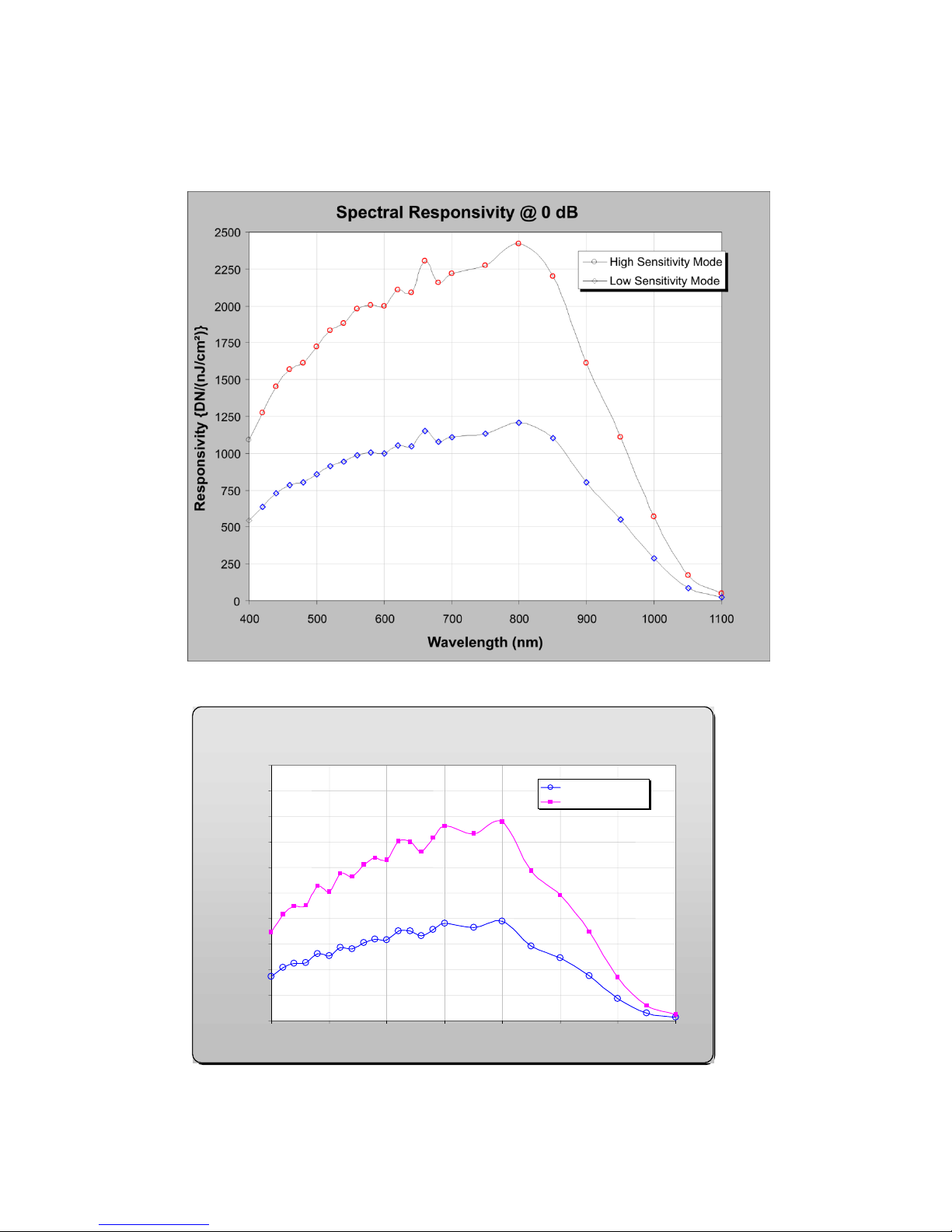
Spectral Responsivity @ 0 dB Gain
0
200
400
600
800
1000
1200
1400
1600
1800
2000
400
500
600
700
800
900
1000
1100
Wavelength (nm)
Low Sensitivity Mode
Hi Sensitivity Mode
12 bits DN/nJ/cm Responsivity
2
Responsivity
Figure 1: Spyder3 GigE Vision 1k and 2k Responsivity
Figure 2: Spyder3 GigE Vision 4k Responsivity
Teledyne DALSA 03-032-20123-00

12 Spyder3 GigE Vision SG-14 Cameras User’s Manual
Mechanicals
Figure 3: Spyder3 1k and 2k GigE Vision Mechanical
03-032-20123-00 Teledyne DALSA
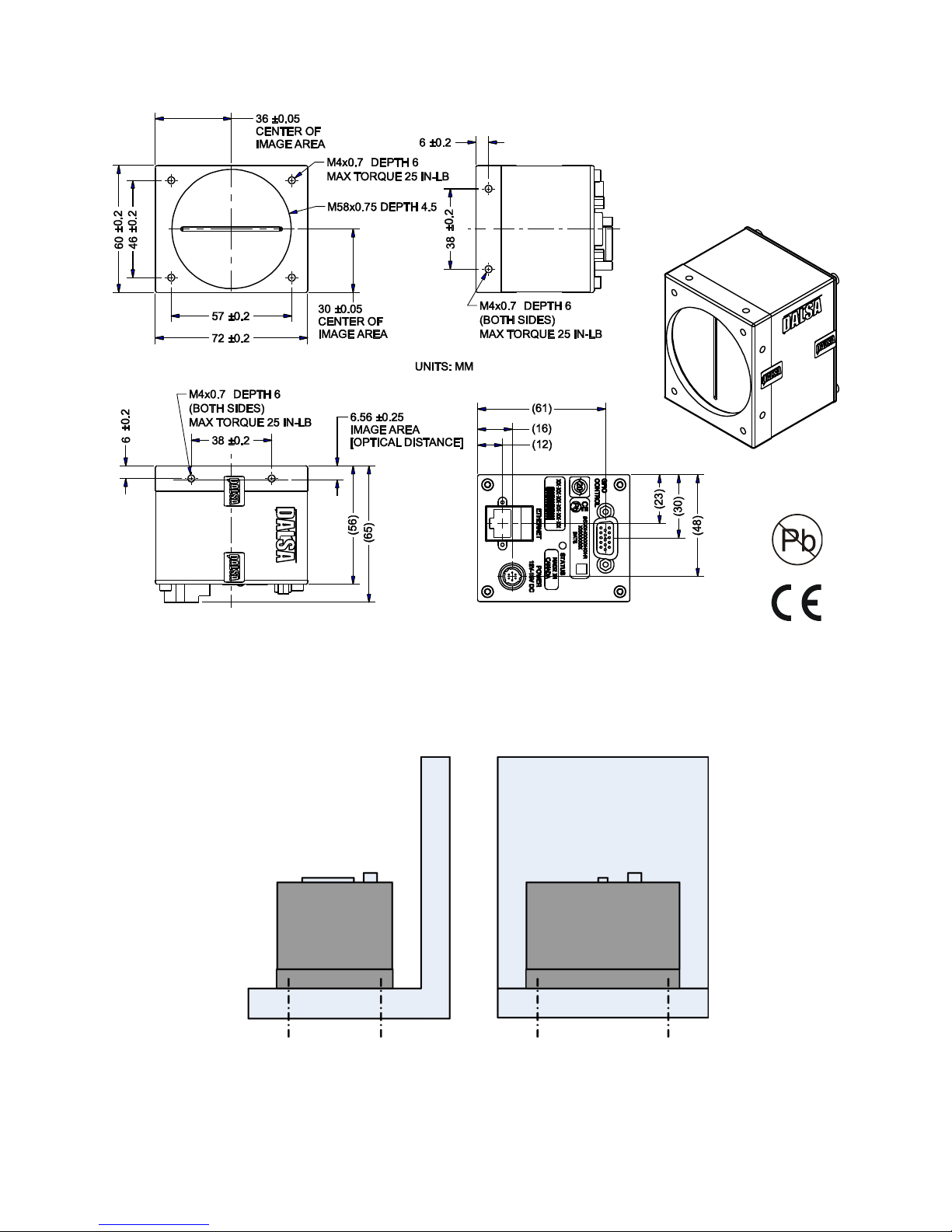
Spyder3 GigE Vision SG-14 Cameras User’s Manual 13
Figure 4: Spyder3 4k GigE Vision Mechanical
Mounting
Heat generated by the camera must be allowed to move away from the camera. Mount the camera on the
frontplate (using the provided mounting holes) with maximum contact to the area for best heat
dissipation.
Figure 5: Spyder3 Mounting Example
Teledyne DALSA 03-032-20123-00
14 Spyder3 GigE Vision SG-14 Cameras User’s Manual
Tap 2Tap 1
CCD Readout Shift Register
CCD Readout Shift Register
N
Pixels
N
Pixels
N
=1024, 2048, 4096
Pixel 1, 1
Tap 1
CCD Readout Shift Register
CCD Readout Shift Register
N
Pixels (14µm x 14µm)
N
Pixels (14µm x 14µm)
N
=1024, 2048
Pixel 1, 1
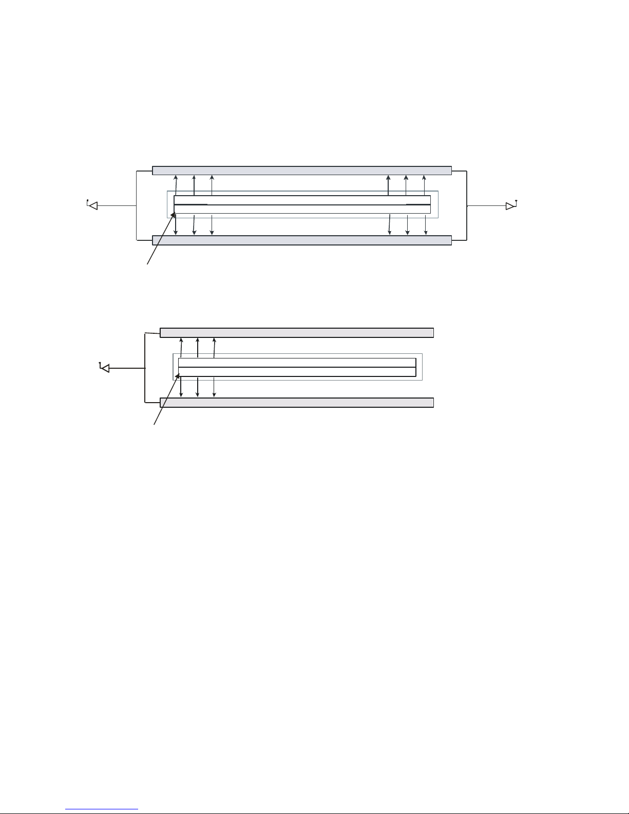
Image Sensor
The cam era u ses Teled yne D ALSA’s d u al line scan sensor. Th e camer a can be configured to read out in
either high or low sensitivity mode, tall pixel mode and forward or reverse shift direction.
Figure 6: 2 Tap Sensor Block Diagram
Figure 7: 1 Tap Sensor Block Diagram (1k and 2k only)
03-032-20123-00 Teledyne DALSA

Spyder3 GigE Vision SG-14 Cameras User’s Manual 15
Software and Hardware Setup
Host System Requirements
To achieve best system performance, the following minimum requirements are recommended:
Operating system: Windows XP Professional, Windows Vista, Windows 7 (either 32-bit or 64-bit for
all) are supported.
Network Adapter Requirements
GigE network adapter (either PCI card or LOM): For high performance you must use a Intel
PRO/ 1000 MT ad apter.
The Spyder3 GEV camera works only with network adapters based on the Intel 82546, 82541, and 82540
network chips. The driver will also function with adapters based on the Intel 82544 chip, but these are not
recommended due to bugs in the chip that can cause control packets to be lost if sent while data is
streaming.
Ethernet Switch Requirements
When you require more than one device on the same network or a camera-to-PC separation of more than
100 metres, you can use an Ethernet switch. Since the Spyder3 GEV camera complies with the Internet
Protocol, the camera should work with all standard Ethernet switches. However, switches offer a range of
functions and performance grades, so care must be taken to choose the right switch for a particular
application.
Setup Steps: Overview
Take the following steps in order to setup and run your camera system. They are described briefly below
and in more detail in the following sections.
1. Install and Configure Ethernet Network Card
If your host computer does not have a Gigabit network adapter or equivalent (PCI bus Gigabit NIC)
already installed, then you need to install one.
For Gigabit performance we recommend the Intel PRO/ 1000 MT adapter, or equivalent. Follow the
manufactu rer’s installation instructions.
A GigE Vision compliant XML device description file is embedded within the cam era’s firmware
allowing GigE Vision compliant applications (e.g. Pleora`s Coyote, and SaperaLT) to recognize the
cam era’s cap abilities im mediately after connection. The Spyder3 camera was tested with and supports
SaperaLT which gives you access to the CamExpert GUI, a GigE Vision compliant application.
Software Installation
Install Sapera LT with CamExpert to control the Spyder3. You can access Sapera drivers, SDKs, and
demos from the following link: http:/ / www.teledynedalsa.com/ mv/ support/ driverSDKlist.aspx
Teledyne DALSA 03-032-20123-00

16 Spyder3 GigE Vision SG-14 Cameras User’s Manual
2. Connect Power, Ethernet and I/O Cables
Connect a power cable from the camera to a +12 VDC to +15 VDC power supply.
Connect the Ethernet cable from the camera to the computer Ethernet jack.
If using the external signals connect the external control cable to the camera.
3. Establish communicating with the camera
Start the GUI and establish communication with the camera.
4. Check camera LED, settings and test pattern
Ensure that the camera is operating properly by checking the LED, the current settings, and by acquiring
a test pattern.
5. Operate the Camera
At this point you will be ready to operate the camera in order to acquire and retrieve images, set camera
functions, and save settings.
03-032-20123-00 Teledyne DALSA
Spyder3 GigE Vision SG-14 Cameras User’s Manual 17
Step 1. Ethernet Network Card: Install and
Configure
Install Network Card
The following network card has been tested and is recommended for use with this camera: Intel Pro/ 1000
MT Desktop Adapter (33-MHz, 32-bit PCI). Order Code: PWLA8391GT (single packs). Follow the
manufactu rer’s recom mend ations t o install this card in the host PC.
Configure Network Card
The configuration shown here uses the Windows XP operating system as the host platform.
The camera communicates using the Ethernet connection and employs the static IP address: 192.168.5.100
(default). A static address ensures the fastest operation. Alternatively, you can use a dynamic IP address.
To configure the network card from the host PC:
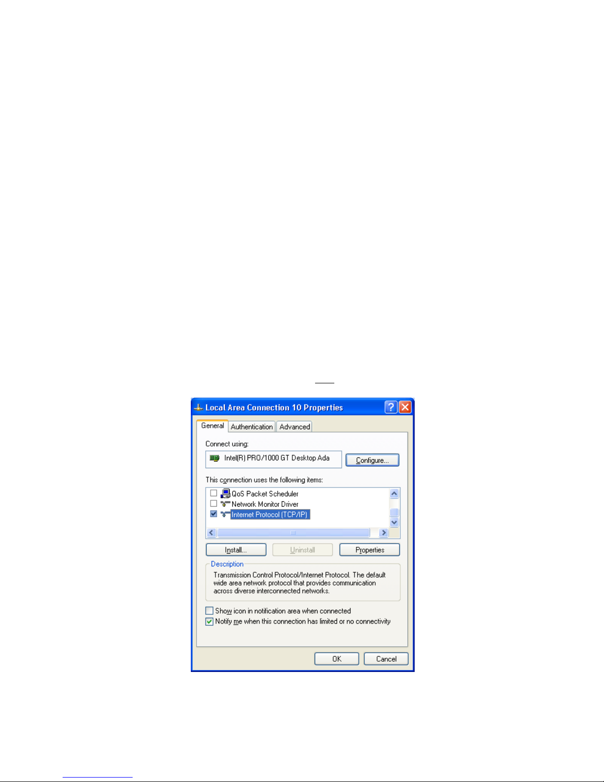
1. In the Start menu under ―Control Panel‖ select ―Netw ork Connections,‖ and configure the
network card as follows:
2. Select the installed network card and click on ―Ch ange settin gs of this con n ectio n .‖
3. Enable the ―Intern et Prot ocol (TCP/ IP)‖ option only.
4. With ―Internet Pr otocol (TCP/ IP)‖ selected , click on the ―Prop erties‖ bu tton .
Teledyne DALSA 03-032-20123-00
Figure 8. Internet Protocol
18 Spyder3 GigE Vision SG-14 Cameras User’s Manual
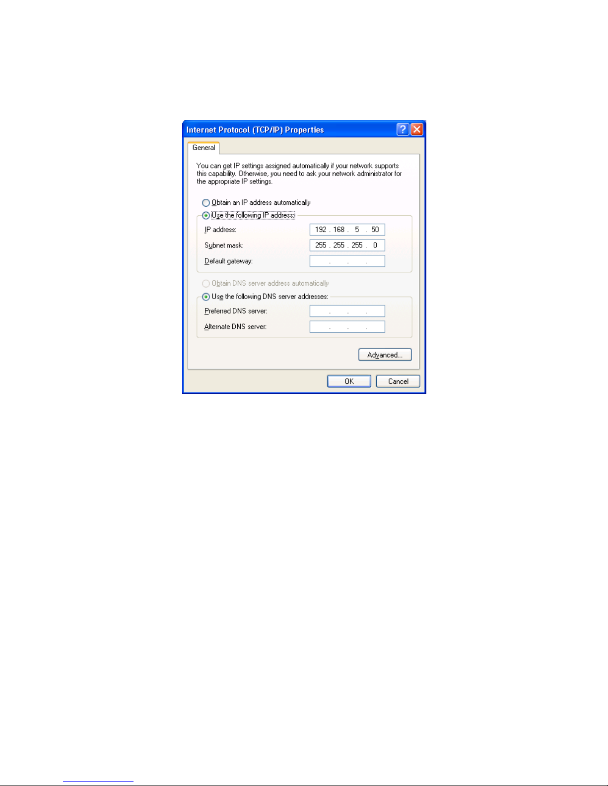
5. Select ―Use the follow in g IP add r ess‖ and set the IP address to an y address in this subnet other
than 192.168.5.100, which is used by the camera. In the example below, the address 192.168.5.50 is
used. Alternativ ely, select ―Obtain an IP ad d r ess au tom atically‖ to u se a d ynam ic add r ess.
6. Set subnet to: 255.255.255.0 an d click on ―OK.‖
Figure 9. IP Address
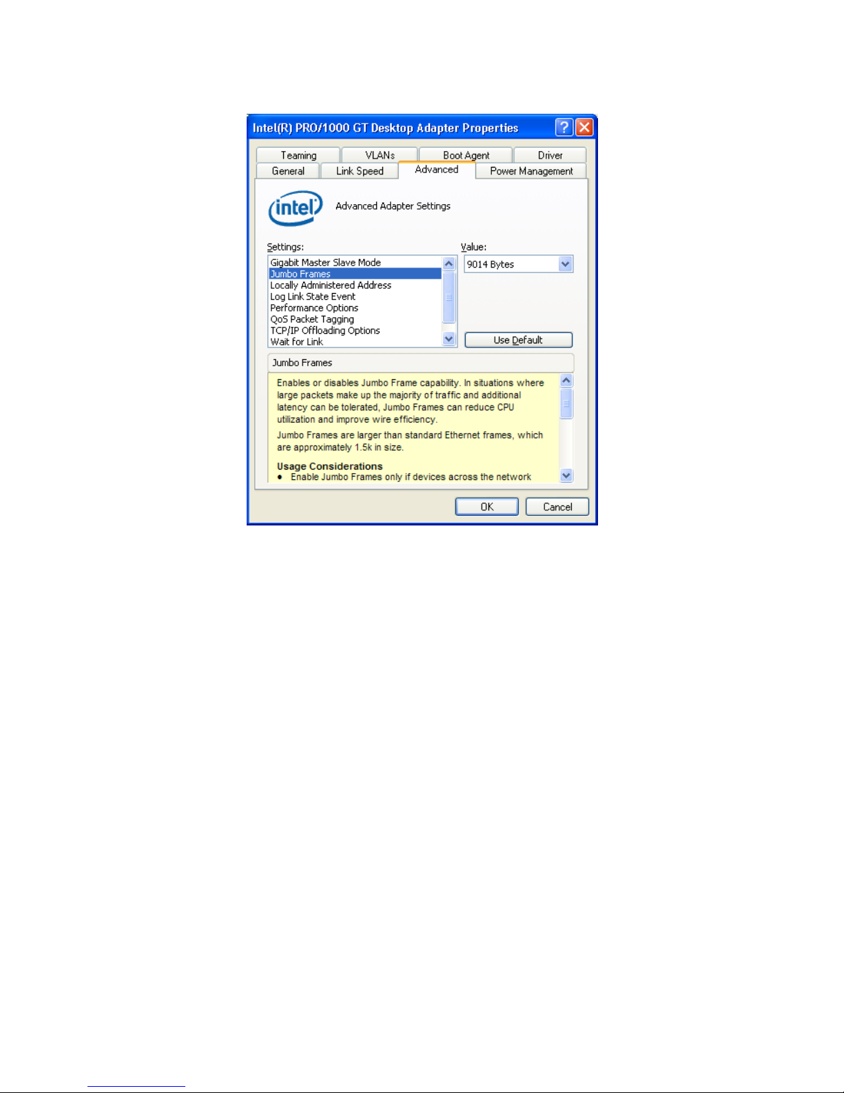
7. Click ―OK‖ t o save settin gs
8. Click on ―C onfigure‖ button an d select ―A d van ced‖ ta b
9. Enable ―Jum bo Fram es‖ to greater th a n 9000 bytes. If your NIC does not support jumbo packets
the image transfer speed will be slower.
03-032-20123-00 Teledyne DALSA
Spyder3 GigE Vision SG-14 Cameras User’s Manual 19
10. Click ―OK‖ to save settin gs
Figure 10. Jumbo Frames
Teledyne DALSA 03-032-20123-00
20 Spyder3 GigE Vision SG-14 Cameras User’s Manual
Pin
Description
1, 2, 3
Supply voltage—Min +12 VDC to Max +15 VDC
4, 5, 6
Ground
Hirose 6-pin Circular Male
5
4
6
2
3
1
Mating Part: HIROSE
HR10A-7P-6S
!
!
Step 2. Connect Power, Ethernet, and Trigger
Cables
WARNING! Grounding Instructions
Static electricity can damage electronic components. Please discharge any static electrical
charge by touching a grounded surface, such as the metal computer chassis, before performing
any hardware installation.
The use of cable types and lengths other than those specified may result in increased emission or
decreased immunity and performance of the camera.
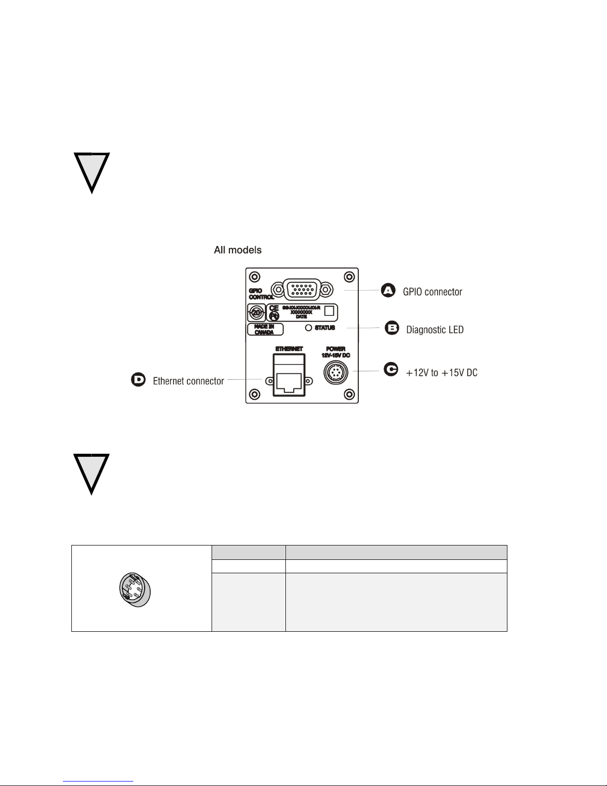
Figure 11: Input and Output, trigger, and Power Connectors
Power Connector
WARNING: It is extremely important that you apply the appropriate voltages to your camera.
Incorrect voltages may damage the camera. Input voltage requirement: +12 V to +15 V DC.
The camera requires a single 6-pin Hirose connector with a single voltage input +12 VDC to +15 VDC for
power. The camera meets all performance specifications using standard switching power supplies,
although well-regulated linear supplies provide optimum performance.
Table 6. Hirose 6-Pin Power Pinout
03-032-20123-00 Teledyne DALSA

Spyder3 GigE Vision SG-14 Cameras User’s Manual 21
!
Priority
Color of Status LED
Meaning
1
Flashing Red
Fatal Error. For example, camera temperature is too high and
camera thermal shutdown has occurred.
2
Flashing Green
Camera initialization or executing a long command .
3
Solid Green
Camera is operational and functioning correctly.
Ethernet Connection
LED@ 1Gbps
Data Transmission LED
WARNING: When setting up the camera’s power supplies follow these guidelines:
Apply the appropriate voltages.
Protect the camera with a 2 amp slow-blow fuse between the power supply and the camera.
Do not use the shield on a multi-conductor cable for ground.
Keep leads as short as possible in order to reduce voltage drop.
Use high-quality linear supplies in order to minimize noise.
Note: If your power supply does not meet these requirements, then the camera performance specifications are not
guaranteed.
Ethernet Connector and Ethernet LED
The camera uses an RJ45 connector and a standard Cat 5 cable for Gigabit Ethernet signals and serial
communications. The device supports 10/ 100/ 1000 Mbit/ s speeds.
Note: Router connection not supported. Connection to a network switch for a single camera is supported.
Ethernet Connection LED
Steady ON indicates that an Ethernet connection is successfully established at 1Gbps.
Data Transmission LED
Steady ON indicates that the camera is ready for data transmission. Flashing indicates that the camera is
transmitting or receiving data.
EMC Compliance
In order to achieve EMC compliance, the Spyder3 camera requires the use of shielded CAT5e or CAT6
Ethernet cables.
Status LED
The camera is equipped with a red/ green LED used to display the status of the camera's operation. The
table below summarizes the operating states of the camera and the corresponding LED states.
When more than one condition is active, the LED indicates the condition with the highest priority. Error
and warning states are accompanied by corresponding messages that further describe the current camera
status.
Teledyne DALSA 03-032-20123-00
22 Spyder3 GigE Vision SG-14 Cameras User’s Manual
Pin
Signal
Description
GenICam Default
1
INPUT_ 0+
LVDS/TTL format (positive)
EXSYNC +
2
INPUT_0-
LVDS (negative)
EXSYNC -
3
INPUT_1+
LVDS/TTL format (positive)
FrameTrig +
4
INPUT_1-
LVDS (negative)
FrameTrig -
5
GND
6
INPUT_2+
LVDS/TTL format (positive)
Direction +
7
INPUT_2-
LVDS (negative)
Direction -
8
INPUT_3
TTL auxiliary input
9
OUTPUT_3
TTL auxiliary output
10
OUTPUT_2+
LVDS/TTL auxiliary output
11
OUTPUT_0+
LVDS/TTL auxiliary output
12
OUTPUT_0-
LVDS (negative)
13
OUTPUT_1+
LVDS/TTL auxiliary output
14
OUTPUT_1-
LVDS (negative)
15
OUTPUT_2-
LVDS (negative)
1
5
11
15
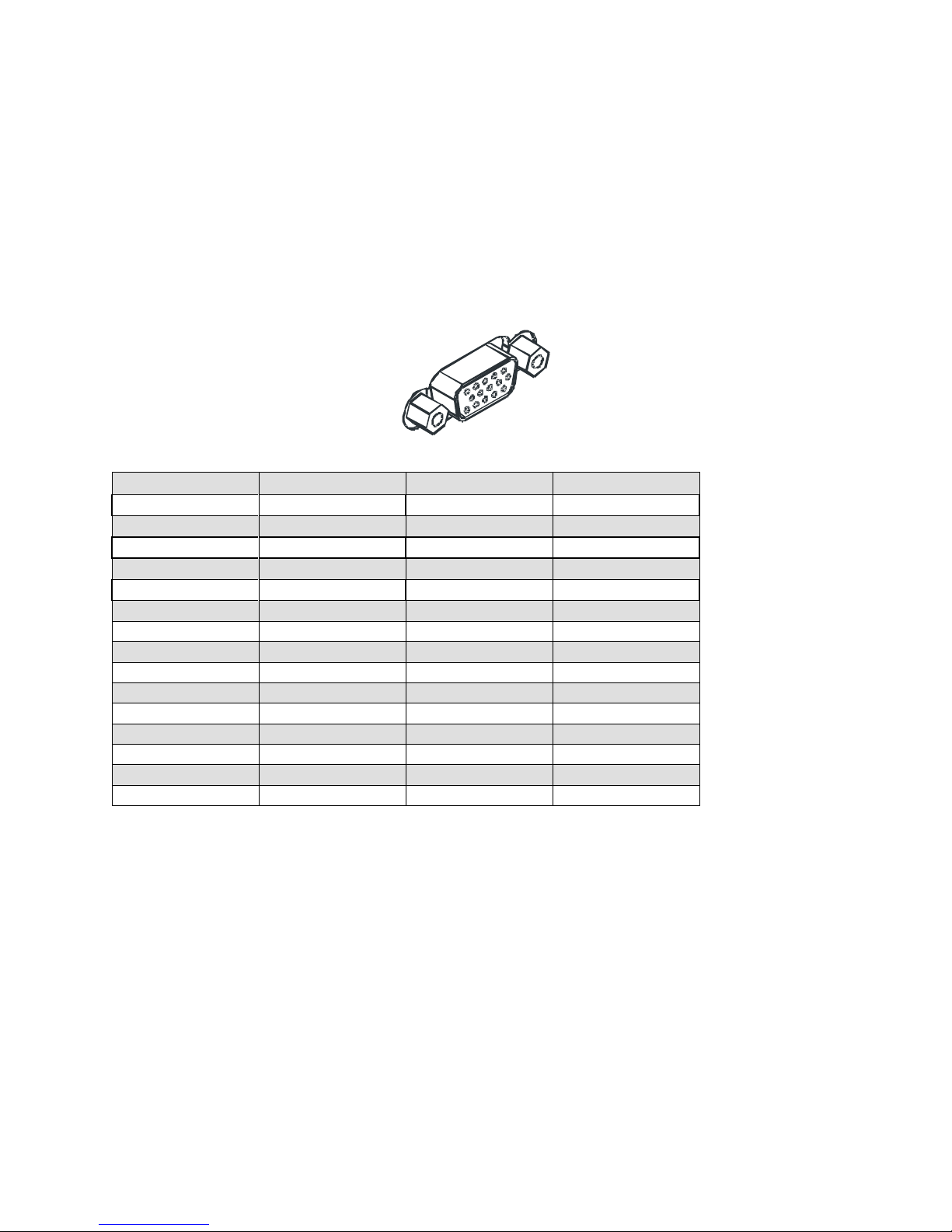
GPIO Connector: External Input
A single 15-pin general purpose input / output (GPIO) connector is used to receive or control external
signals. For example, the GPIO connector can be used to receive EXSYNC, PRIN (pixel reset), and
direction signals.
The GPIO connector is programmed through the GUI application. In CamExpert the relevant parameters
are located in the category Inputs Group.
Figure 12: GPIO Connector and Pin Numbers
Table 7: GPIO Connector Pinout
A schematic of the TTL input circuitry is shown in
Figure 13: TTL Input Schematic. The input signals are fed into the engine from external sources via the
GPIO connector.
GPIO Isolation
All of the GPIOs are isolated from the rest of the camera and the camera case. They are not isolated with
respect to each other and share a common return (ground) through pin 5 of the GPIO connector.
Note: The shell connection of the GPIO connector is not isolated and it should not be used as a return
(ground) for the GPIO signals. The shell connection is attached to the camera case.
GPIO Configuration
Refer to Appendix C: GPIO Control for a detailed description of the GPIO use-cases and configuration
options.
03-032-20123-00 Teledyne DALSA
Spyder3 GigE Vision SG-14 Cameras User’s Manual 23
1000
3.3V
3.3V
TTL
100
ESD
Protection
5V
100
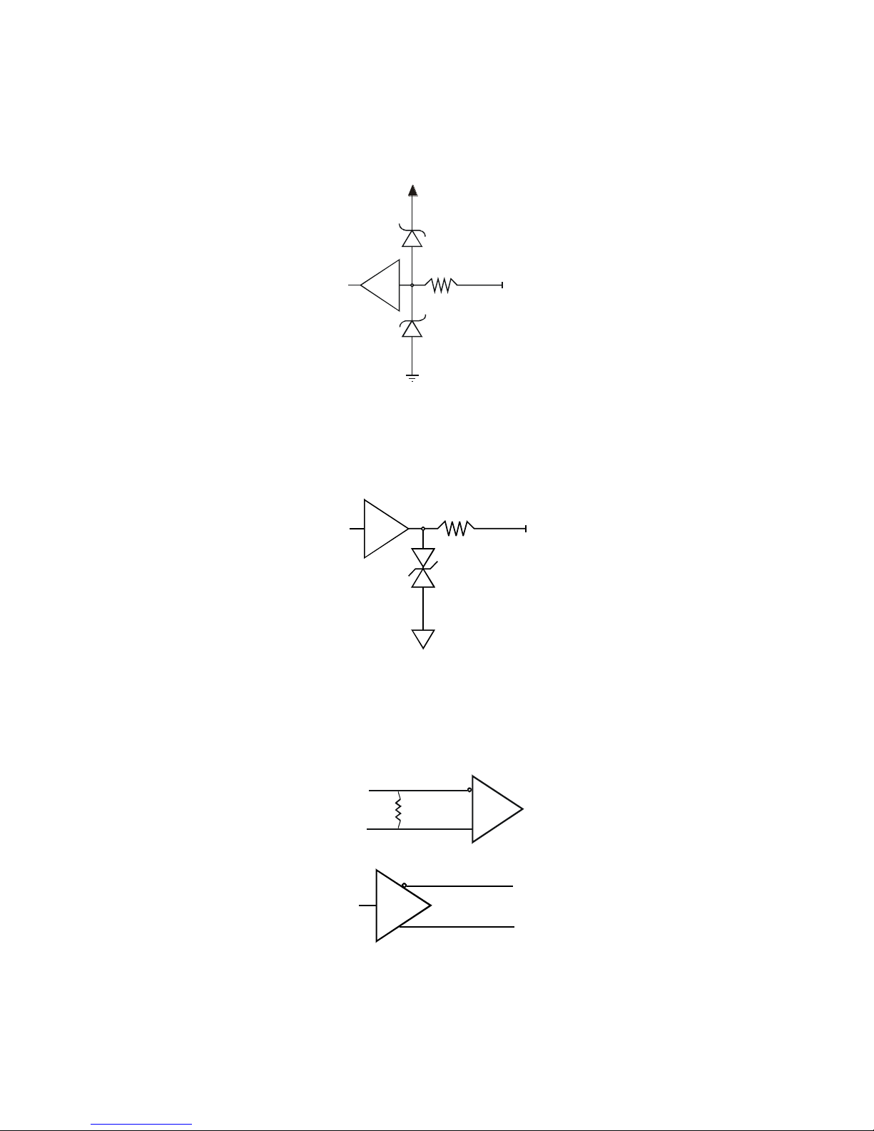
TTL Inputs and Outputs
Figure 13: TTL Input Schematic
Termination: 1000 Ω series
Input current: minimum 0 nA; maximum 2 mA
Input voltage: maximum of low 0.66 V; minimum of high 2.6 V
TTL inputs are maximum 5 V and 3.3 V logic tolerant
Figure 14: TTL Output Schematic
Termination: 100 Ω series
Output current: sink 50 mA; source 50 mA
Output voltage: maximum of low 0.55 V @ 32mA; minimum of high 3.8 V @ 32mA.
LVDS Inputs and Outputs (LVDS compliant)
Figure 15: LVDS Input
Figure 16Figure 17: LVDS Output
Teledyne DALSA 03-032-20123-00

24 Spyder3 GigE Vision SG-14 Cameras User’s Manual
Step 3. Establish Communication with the
Camera
Power on the camera
Turn on the cam era’s p ow er su pp ly . You may h ave to w ait u p to 60 second s w h ile the camera w arm s up
and prepares itself for operation.
Connect to the camera
1. Start a new Sapera CamExpert application (or equivalent GigE Vision compliant interface) by doubleclicking the desktop icon created during the softw are installation.
2. CamExpert will search for installed Sapera devices. In the Devices list area on the left side, the
connected Spyder camera will be shown.
3. Select the Spyder camera device by clicking on the camera user-defined name. By default the camera is
identified by its serial number.
Check LED Status
If the camera is operating correctly at this point, the diagnostic LED will flash for 10 seconds and then
turn solid green.
Software Interface
All the camera features can be controlled through the CamExpert interface. For example, under the
Sensor Control menu in the camera window you can control the frame rate and exposure times.
03-032-20123-00 Teledyne DALSA

Spyder3 GigE Vision SG-14 Cameras User’s Manual 25
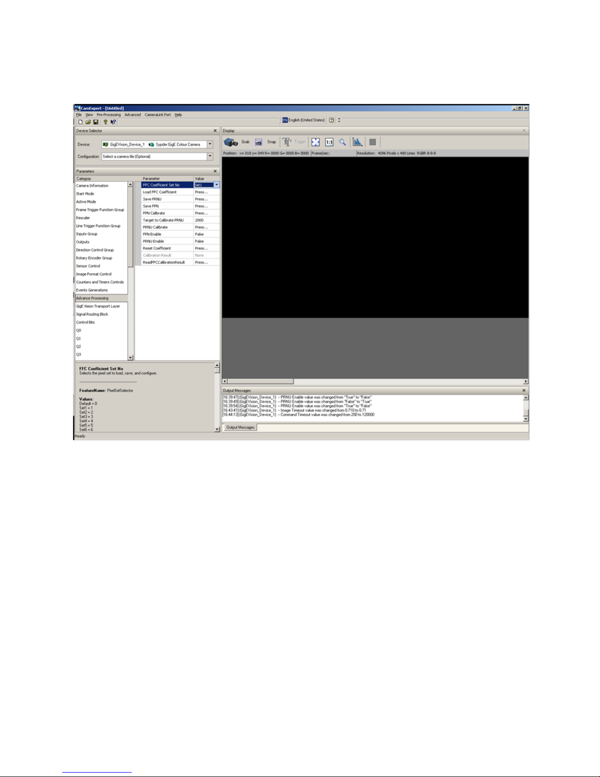
Using Sapera CamExpert with Spyder3 Cameras
CamExpert is the camera interfacing tool supported by the Sapera library. When used with a Spyder3
camera, CamExpert allows a user to test all Spyder3 operating modes. Additionally CamExpert saves the
Spyder3 user settings configuration to the camera or saves multiple configurations as individual camera
parameter files on the host system (*.ccf).
An important component of CamExpert is its live acquisition display window which allows immediate
verification of timing or control parameters without the need to run a separate acquisition program.
For context sensitive help, click on the button then click on a camera configuration parameter. A
short description of the configuration parameter will be shown in a popup. Click on the button to
open the help file for more descriptive information on CamExpert.
The central section of CamExpert provides access to the Spyder3 parameters. Note: The availability of the
parameters is dependent on the CamExpert user setting.
Teledyne DALSA 03-032-20123-00
26 Spyder3 GigE Vision SG-14 Cameras User’s Manual
CamExpert Panes
The CamExpert application uses 5 windows to simplify choosing and configuring camera files or
acquisition parameters for the installed device.
Device Selector pane: View and select from any installed Sapera acquisition device. Once a device is
selected CamExpert will only present acquisition parameters applicable to that device. Optionally
select a camera file included with the Sapera installation or saved by the user.
Parameters pane: Allows viewing or changing all acquisition parameters supported by the
acquisition device. CamExpert displays parameters only if those parameters are supported by the
installed device. This avoids confusion by eliminating parameter choices when they do not apply to
the hardware in use.
Display pane: Provides a live or single frame acquisition display. Frame buffer parameters are shown
in an information bar above the image window.
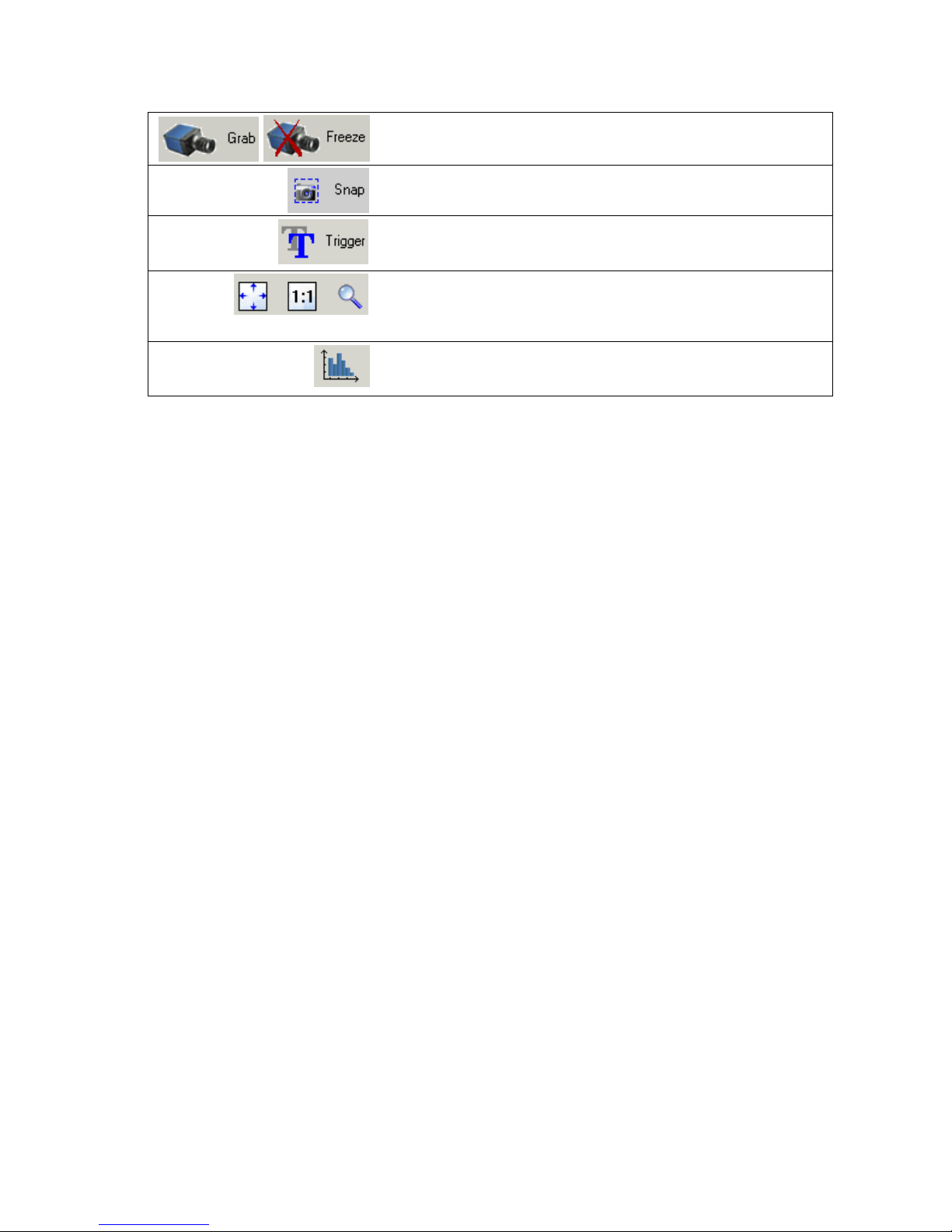
Control Buttons: The Display pane includes CamExpert control buttons. These are:
03-032-20123-00 Teledyne DALSA
Spyder3 GigE Vision SG-14 Cameras User’s Manual 27
Acquisition control button:
Click once to start live grab, click again to stop.
Single frame grab:
Click to acquire one frame from device.
Software trigger button:
With the I/ O control parameters set to Trigger Enabled / Software
Trigger type, click to send a single software trigger command.
CamExpert display controls:
(these do not modify the frame buffer data)
Stretch image to fit, set image display to original size, or zoom the
image to any size and ratio.
Histogram / Profile tool:
Select to view a histogram or line/ column profile during live
acquisition.
Output Message pane: Displays messages from CamExpert or the device driver.
Teledyne DALSA 03-032-20123-00

28 Spyder3 GigE Vision SG-14 Cameras User’s Manual
Step 4. Camera Settings and Test Patterns
Review a Test Pattern Image
The camera is now ready to retrieve a test pattern. The Spyder3 cameras include a built-in test pattern
generator that can be used to confirm camera Ethernet connections without the need for a camera lens or
proper lighting. The test patterns are useful for verifying camera timing and connections, and to aid in
system trouble shooting.
Using CamExpert, select Image Format Control > Test Image Selector and choose one of the available
test images. Select live grab to see the pattern output. The following test patterns are available:
Figure 18. Grey horizontal step
Figure 19. Grey horizontal ramp
03-032-20123-00 Teledyne DALSA

Spyder3 GigE Vision SG-14 Cameras User’s Manual 29
At this point you are ready to start operating the camera in order to acquire images, set camera functions,
and save settings.
Camera Operation
Factory Settings
The camera ships and powers up for the first time with the following factory settings:
High sensitivity mode
Forward CCD shift direction
8 bit, 2 tap
No binning
Exposure mode: internal sync & maximum exposure time
5, 000 Hz line rate
Factory calibrated analog gain and offset
Factory calibrated FPN and PRNU coefficients
Teledyne DALSA 03-032-20123-00

30 Spyder3 GigE Vision SG-14 Cameras User’s Manual
Camera Information
Parameter
Options
Manufacturer Name
Model Name
Manufacturer Info
Camera Version
Firmware Version
Camera serial ID number
Camera Temperature
Camera Voltage
User ID
Define a camera name up to 64 characters
Read temperature
In general, the temperature read is 15 C greater than the temperature at the front
plate. The temperature should not exceed 80 °C.
Read Camera input voltage
Click to read the voltage from the camera
Read Only Parameters
Check Camera and Sensor Information
Camera and sensor information can be retrieved via a controlling application—in the examples shown here,
CamExpert. Parameters such as camera model, firmware version, sensor characteristics, etc. are read to uniquely
identify the connected device.
The camera information parameters are grouped together as members of the Camera Information set.
GigE Vision Input Controls
Verify Temperature and Voltage
To determine the voltage and temperature at the camera, use the Read Voltage and Temperature feature
found in the Camera Information set.
The temperature returned is the internal chip case temperature in degrees Celsius. For proper operation,
this value should not exceed 80 °C. If the camera exceeds the designated temperature it will shut down
an d w ill not tu rn on u ntil th e camer a’s temp erature is 73 ºC or less. Use the reset camera function.
The voltage d isp layed is t h e cam er a’s inpu t volt age. N ote that the voltage measurement feature of the
camera provides only approximate results (typically within 10%). The measurement should not be used
to set the applied voltage to the camera, but only used as a test to isolate gross problems with the supply
voltage.
03-032-20123-00 Teledyne DALSA
 Loading...