

Teledyne Spyder3 SC-34-02K80-00-R, Spyder3 SC-34-04K80-00-R User Manual
Spyder3 SC-34
31 May 2013
03-032-20116-01
www.teledynedalsa.com
Color Camera User’s Manual
SC-34-02K80-00-R
SC-34-04K80-00-R

2 Spyder3 SC-34 Color Camera User's Manual
Teledyne DALSA Sales Offices
North America
Europe
Asia Pacific
700 Technology Park Drive
Billerica, MA
USA, 01821
Tel: 978-670-2000
Fax: 978-670-2010
sales.americas@teledyned alsa.com
support@teledynedalsa.com
Teledyne DALSA GmbH
Felix-Wankel-Strasse 1
D-82152 Krailling (Munich)
Germany
Tel: +49 - 89 - 89545730
Fax: +49 - 89 – 895457346
sales.europe@teledynedalsa.com
support@teledynedalsa.com
Ikebukuro East 1 3F
3-4-3 Higashi Ikebukuro
Toshima-ku, Tokyo
Japan
+81 3 5960 6353 (phone)
+81 3 5960 6354 (fax)
sales.asia@teledynedalsa.com
support@teledynedalsa.com
© 2013 Teledyne DALSA. All information provided in this manual is believed to be accurate and reliable.
No responsibility is assumed by Teledyne DALSA for its use. Teledyne DALSA reserves the right to
make changes to this information without notice. Reproduction of this manual in whole or in part, by any
means, is prohibited without prior permission having been obtained from Teledyne DALSA.
About Teledyne Technologies and Teledyne DALSA, Inc.
Teledyne Technologies is a leading provider of sophisticated electronic subsystems, instrumentation and
communication products, engineered systems, aerospace engines, and energy and power generation
systems. Teled yn e Technologies‘ operation s are p rimarily located in the U n ited States, the United
Kingd o m an d Mexico. For m ore in form ation, visit Teled yn e Technologies‘ website at ww w .teled yne.com .
Teledyne DALSA, a Teledyne Technologies company, is an international leader in high performance
digital imaging and semiconductors with approximately 1,000 employees worldwide, headquartered in
Waterloo, Ontario, Canada. Established in 1980, the company designs, develops, manufactures and
markets digital imaging products and solutions, in addition to providing MEMS products and services.
For more inform ation, visit Teled yn e DALSA‘s w ebsite at w w w .teled y n ed alsa.com.
For further information not included in this manual, or for information on Teled yne DALSA‘s extensive
line of image sensing products, please call:
Industry Standards
Teledyne DALSA and this model of the Spyder3 camera support th e Cam er a Lin k™ com mu n icat io n s
interface for vision applications. Camera Link is a high speed communications interface for vision
applications. It provides a stand ard method of communication between digital cameras and frame
grabbers.
Detailed information on Camera Link is available in the Teledyne DALSA Camera Link Implementation
Road Map documentation, available from the Knowledge Center on our Web site:
(http:/ / www.teledynedalsa.com/ mv/ knowledge/ appnotes.aspx).
03-032-20116-01 Teledyne DALSA

Spyder3 SC-34 Color Camera User's Manual 3
Contents
THE SPYDER3 SC-34 CAMERA .................................................................................................................................................. 5
1.1 CAMERA HIGHLIGHTS ........................................................................................................................................................................................................5
1.2 CAMERA PERFORMANCE SPECIFICATIONS ..............................................................................................................................................................................7
1.3 IMAGE SENSOR .................................................................................................................................................................................................................9
1.4 RESPONSIVITY ..................................................................................................................................................................................................................9
MECHANICALS....................................................................................................................................................................... 11
3.1 MECHANICAL INTERFACE ..................................................................................................................................................................................................11
SOFTWARE AND HARDWARE SETUP ..................................................................................................................................... 14
STEP 1. INSTALL AND CONFIGURE THE FRAME GRABBER AND GRAPHICS CARD .................................................................................................................................15
STEP 2. CONNECT POWER AND CAMERA LINK CABLES.................................................................................................................................................................15
2.1 POWER CONNECTOR ........................................................................................................................................................................................................16
2.2 CAMERA LED .................................................................................................................................................................................................................17
2.3 CAMERA LINK DATA CONNECTOR .......................................................................................................................................................................................17
2.4 CAMERA LINK VIDEO TIMING ............................................................................................................................................................................................19
STEP 3. ESTABLISH COMMUNICATION WITH THE CAMERA ............................................................................................................................................................21
3.1 USING CAMERA LINK WITH SPYDER3 CAMERAS ....................................................................................................................................................................22
3.2 FIRST POWER UP CAMERA SETTINGS .................................................................................................................................................................................23
3.3 SENSOR OUTPUT FORMAT ................................................................................................................................................................................................24
3.4 EXPOSURE MODE, LINE RATE AND EXPOSURE TIME ..............................................................................................................................................................26
3.5 COLOR COMMANDS..........................................................................................................................................................................................................33
3.6 DATA PROCESSING ..........................................................................................................................................................................................................35
3.7 ANALOG AND DIGITAL SIGNAL PROCESSING CHAIN ..............................................................................................................................................................35
3.8 END-OF-LINE SEQUENCE ..................................................................................................................................................................................................42
3.9 SAVING AND RESTORING SETTINGS ....................................................................................................................................................................................43
3.10 SAVING AND RESTORING PRNU AND FPN COEFFICIENTS ...................................................................................................................................................44
3.11 SAVING AND RESTORING USER SETTINGS USING X-MODEM ................................................................................................................................................45
3.12 TEST PATTERNS ............................................................................................................................................................................................................49
3.13 RETURNING VIDEO INFORMATION ....................................................................................................................................................................................50
3.14 TEMPERATURE MEASUREMENT ........................................................................................................................................................................................51
3.15 VOLTAGE MEASUREMENT ...............................................................................................................................................................................................51
3.16 CAMERA FREQUENCY MEASUREMENT ................................................................................................................................................................................51
3.17 RETURNING THE LED STATUS .........................................................................................................................................................................................52
3.18 RETURNING CAMERA SETTINGS .......................................................................................................................................................................................52
3.19 ASCII COMMANDS: REFERENCE ......................................................................................................................................................................................54
3.20 ERROR HANDLING .........................................................................................................................................................................................................58
CLEARING DARK CURRENT .................................................................................................................................................... 60
APPENDIX A .......................................................................................................................................................................... 63
CAMERA LINK™ REFERENCE, TIMING, AND CONFIGURATION TABLE .............................................................................................................................................63
CAMERA LINK BIT DEFINITIONS...............................................................................................................................................................................................64
CAMERA LINK CONFIGURATION TABLES ....................................................................................................................................................................................65
APPENDIX B .......................................................................................................................................................................... 68
EMC DECLARATION ...............................................................................................................................................................................................................68
APPENDIX C .......................................................................................................................................................................... 69
Teledyne DALSA 03-032-20116-01

4 Spyder3 SC-34 Color Camera User's Manual
TROUBLESHOOTING ...............................................................................................................................................................................................................69
SPECIFIC SOLUTIONS .............................................................................................................................................................................................................71
APPENDIX D .......................................................................................................................................................................... 73
ELECTROSTATIC DISCHARGE AND THE CCD SENSOR ....................................................................................................................................................................73
PROTECTING AGAINST DUST, OIL AND SCRATCHES ....................................................................................................................................................................73
CLEANING THE SENSOR WINDOW ............................................................................................................................................................................................73
REVISION HISTORY ............................................................................................................................................................... 75
INDEX.................................................................................................................................................................................... 76
03-032-20116-01 Teledyne DALSA

Spyder3 SC-34 Color Camera User's Manual 5
The Spyder3 SC-34 Camera
The Spyder3 color Camera Link camera uses Teled yne DALSA‘s state-of-the-art dual line scan technology
in order to deliver high color quality, low -cost and ease of use for color imaging. This camera features 2k
and 4k resolutions with a maximum line rate of 18 kHz. The zero gap between the two sensor lines
minimizes image artifact. Customer selectable output formats, RGB, RG/ GB, and G, provides greater
flexibility to meet many application requirements.
1.1 Camera Highlights
Features
2048 or 4096 pixels, 14 µm x 14 µm (2k) and 10 µm x 10 µm (4k) pixel pitch, 100% fill factor
80 mega pixels per second throughput
Up to 18 kHz (2k) or 9 kHz (4k) line rates
RGB, RG/ GB, or G color output formats
Dynamic range 60 dB
Base Camera Link configuration (8 or 12 bit)
RoHS and CE compliant (pending)
Pre-calibrated light sources (e.g. white LED)
Programmability
Serial inter face (ASCII, 9600 baud , ad justable to 19200, 57600, 115200), through Cam era Link™.
Mirroring and forward/ reverse control.
Programmable gain, offset, exposure time and line rate, trigger mode, test pattern output, and
camera diagnostics.
Flat-field correction—minimizes lens vignetting, non-uniform lighting, and sensor FPN and PRNU.
Applications
The Spyder3 Color camera is ideal for:
Cotton and textile inspection
Food, drug and tobacco inspection
Wood, tile, and steel inspection
Postal sorting
Recycling sorting
100 % print inspection (lottery tickets, stamps, bank notes, pay checks, etc.)
General web inspection
Teledyne DALSA 03-032-20116-01

6 Spyder3 SC-34 Color Camera User's Manual
Model
Description
SC-34-02K80-00-R
2k resolution, 2 sensor taps. Base Camera Link configuration.
SC-34-04K80-00-R
4k resolution, 2 sensor taps. Base Camera Link configuration.
Accessory
Description
AC-UC-00002-00-R
M42 TO C-MOUNT ADAPTER RH
AC-SU-00113-00-R
TRIPOD MOUNT ROHS SPYDER3
AC-UN-00002-00-R
M42 TO F-MOUNT ADAPTER RH , 2k model
AC-UN-00003-00-R
M42 TO F-MOUNT ADAPTER RH , 4k model
Camera Models
The Spyder3 color camera is available in these models.
Table 1: Camera Models Overview
Table 2: Camera Accessories
03-032-20116-01 Teledyne DALSA

Spyder3 SC-34 Color Camera User's Manual 7
Feature / Specification
2k
4k
Imager Format
Bilinear CCD
Resolution
2048 pixels (2046 interpolated)
4096 pixels (4094 interpolated)
Pixel Fill Factor
100%
Pixel Size
14 µm x 14 µm
10 µm x 10 µm
Antiblooming
100x
Gain Range
0 to 20 dB
Optical Interface
2k
4k
Lens Mount
M42 x 1 thread
M58 x 0.75
Lens Mount Adapters*
C and F
F
Back Focal Distance
6.56 ± 0.25 mm
Sensor Alignment
x
y
z
z
± 50 µm
± 50 µm
± 0.25 mm
± 0.2°
Mechanical Interface
2k
4k
Camera Size
72(h) x 60(w) x 60(l) mm
60 (h) x 72(w) x 60(l) mm
Mass
< 300 g
300 g
Connectors
pow er connector
data connector
6 pin male Hirose
MDR26 female
Electrical Interface
2k
4k
Input Voltage
+12 to +15 Volts
Power Dissipation
< 9 W
< 9 W
Operating Temperature
0 °C to 65 °C (measured at front plate)
Bit Wid th
8 or 12 bit user selectable Bits
Output Data Configuration
Base Camera Link
Speed
2k
4k
Maximum Line Rate
18 000 Hz
9 000 Hz
Minimum line rate
300 Hz
300 Hz
1.2 Camera Performance Specifications
Table 3: Camera Performance Specifications
*Lens mount adapters are available. Contact Teledyne DALSA Sales for more information.
Teledyne DALSA 03-032-20116-01

8 Spyder3 SC-34 Color Camera User's Manual
Specs
Unit
0 dB
10 dB
+20 dB
Min
Typ
Max
Min
Typ
Max
Min
Typ
Max
Broadband
responsivity
DN /
(nJ / cm²)
2k
— 126.4
— — 400 — —
1264
—
4k
— 64 — —
201.6
— — 784
—
Random noise
rms
DN
— 3 6.5 — 9.2
20.5 — 30
65
Dynamic range
DN:DN
—
1300:1
— — 428:1
— — 130:1
—
FPN global
DN p-p
Uncorrected
— —
52.8 — —
169.6
— — 536
Corrected
— —
32 — —
32 — —
64
PRNU ECD
Uncorrected local
%
— — 8.5 — —
8.5 — —
11.5
Uncorrected global
%
— — 10 — —
10 — —
10
Corrected local
DN p-p
— — 80 — —
80 — —
95
Corrected global
DN p-p
— — 80 — —
80 — —
95
PRNU ECE
Uncorrected local
%
— — 8.5 — —
12 — —
37
Uncorrected global
%
— — 10 — —
12 — —
37
Corrected local
DN p-p
— — 80 — —
237 — —
752
Corrected global
DN p-p
— — 80 — —
208 — —
752
SEE (calculated)
nJ/cm²
2k
— 31 — —
9.8 — —
3.1
—
4k
— 62 — —
20 — —
6.2
—
NEE (calculated)
pJ/cm²
2k
— 23.7 — —
23.7 — —
23.7
—
4k
— 46.8 — —
46.8 — —
46.8
—
Saturation output
amplitude
DN
— — — — 3968±80
— — —
—
DC offset
DN
— — 32 — — — — — —
Table 4: Camera Operating Specifications (Single Color)
Test conditions unless otherwise noted:
12-bit values, Flat Field Correction (FFC) enabled.
CCD Pixel Rate: 40 Megapixels/ second per sensor tap.
Line Rate: 5000 Hz.
Nominal Gain setting unless otherwise specified.
Light Source: Broadband Quartz Halogen, 3250 k, with 750 nm high-pass filter and BG38 filter
installed.
Ambient test temperature 25 °C.
Unless specified, all values are referenced at 12 bit.
Exposure mode disabled.
Notes
1. PRNU measured at 50% SAT.
03-032-20116-01 Teledyne DALSA

Spyder3 SC-34 Color Camera User's Manual 9
Compliance
The CE Mark, FCC Part 15, and Industry Canada ICES-003 Evaluation of the DALSA Spyder3 CL SC-34 cameras
meet the following requirements:
EN 55022 Class A, EN 55011 Class A, and FCC Part 15 Class A emissions requirements; EN 55024, and EN 61326-1
immunity to disturbances.
Tap 2Tap 1
CCD Readout Shift Register
CCD Readout Shift Register
N
Pixels (14 µm x 14 µm or 10 µm x 10 µm)
N
Pixels (14 µm x 14 µm or 10 µm x 10 µm)
N
= 2048, 4096
Pixel 1, 1
R R
R
R R RB B B B B B
G G G G G G G
G
G G G G
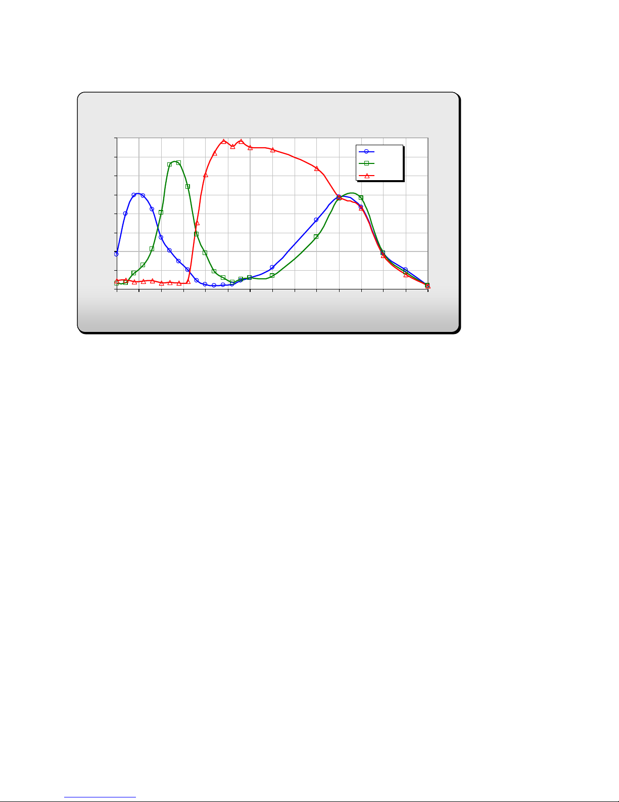
Spyder 2K Spectral Responsivity
0
10
20
30
40
50
60
70
80
90
100
400 450 500 550 600 650 700 750 800 850 900 950 1000 1050 1100
Wavelength [nm]
Responsivity [DN/(nj/cm2)]
Blue
Green
Red
Certifications
Table 5: EMC Compliance Standards
1.3 Image Sensor
The Spyder3 Color bilinear camera is based on Teledyne DALSA‘s d u al line scan CCD sensor. The
bilinear sensor has two lines. The first line has red (R) and blue (B) pixel alternatively, while the second
line has all green (G) pixels. There is no gap in between the two lines and this minimizes any artifact due
to spatial correction. The G channel can be used as a monochrome output. The sensor has a 2 tap output.
Figure 1: Bilinear sensor used in Spyder3 Color (block diagram)
1.4 Responsivity
Figure 2: Spyder3 Color 2k Responsivity
Teledyne DALSA 03-032-20116-01
10 Spyder3 SC-34 Color Camera User's Manual
Spyder 3 4K Spectral Responsivity
0
5
10
15
20
25
30
35
40
400 450 500 550 600 650 700 750 800 850 900 950 1000 1050 1100
Wavelength [nm]
Responsivity [DN/(nj/cm2)]
Series1
Series2
Series3
Figure 3: Spyder3 Color 4k Responsivity
03-032-20116-01 Teledyne DALSA

Spyder3 SC-34 Color Camera User's Manual 11
Mechanicals
3.1 Mechanical Interface
Figure 4: 2k Mechanical Dimensions
[ADD MECHANICAL PDF HERE]
Teledyne DALSA 03-032-20116-01

12 Spyder3 SC-34 Color Camera User's Manual
Figure 5: 4k Mechanical Dimensions
[ADD MECHANICAL PDF HERE]
03-032-20116-01 Teledyne DALSA
Spyder3 SC-34 Color Camera User's Manual 13
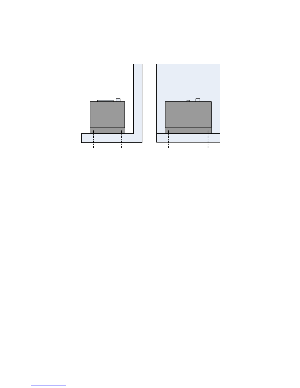
Mounting
Heat generated by the camera must be allowed to move away from the camera. Mount the camera on the
front plate (using the provided mounting holes) with maximum contact to the area for best heat
dissipation.
Figure 6: Spyder3 Mounting Example
Teledyne DALSA 03-032-20116-01

14 Spyder3 SC-34 Color Camera User's Manual
Software and Hardware Setup
Host System Requirements
To achieve best system performance, the following minimum requirements are recommended:
Base Camera Link frame grabber.
Operating system: Windows XP Professional, Windows Vista, Windows 7 (either 32-bit or 64-bit for
all) are supported.
Setup Steps: Overview
Take the following steps in order to setup and run your camera system. They are described briefly below
and in more detail in the following sections.
1. Install and Configure Frame Grabber
If your host computer d oes not have a Base Camera Link frame grabber, or equivalent, then you need to
install one.
2. Connect Power, and Camera Link I/O Cables
Connect a power cable from the camera to a +12 VDC to +15 VDC power supply.
If using the external signals connect the external control cable to the camera.
3. Establish communicating with the camera
The quickest and easiest way to communicate with the camera is through the u se of a terminal program
(e.g., Microsoft HyperTerminal is a widely available application).
4. Check camera LED, settings and test pattern
Ensure that the camera is operating properly by checking the LED, the current settings, and by acquiring
a test pattern.
5. Operate the Camera
At this point you will be ready to operate the camera in order to acquire and retrieve images, set camera
functions, and save settings.
03-032-20116-01 Teledyne DALSA

Spyder3 SC-34 Color Camera User's Manual 15
!
Step 1. Install and configure the frame grabber
and graphics card
Install Frame Grabber
Install a Base Cam era Link frame gr abber accord ing to the m anu factu r er‘s d escr iption.
A list of frame grabbers recommended by Teledyne DALSA and supporting the Spyder3 cameras is
available on the Teledyne DALSA Web site here:
www.teledynedalsa.com/ mv/ products/ framegrabbers.aspx
Install Graphics Card
Determ ine th e grap hics card that su pp orts you r selected fr am e grab ber an d follow th e m a n u factu rer‘s
installation instructions.
Step 2. Connect Power and Camera Link Cables
WARNING! Grounding Instructions
Static electricity can damage electronic components. Please discharge any static electrical
charge by touching a grounded surface, such as the metal computer chassis, before performing
any hardware installation.
The use of cable types and lengths other than those specified may result in increased emission or
decreased immunity and performance of the camera.
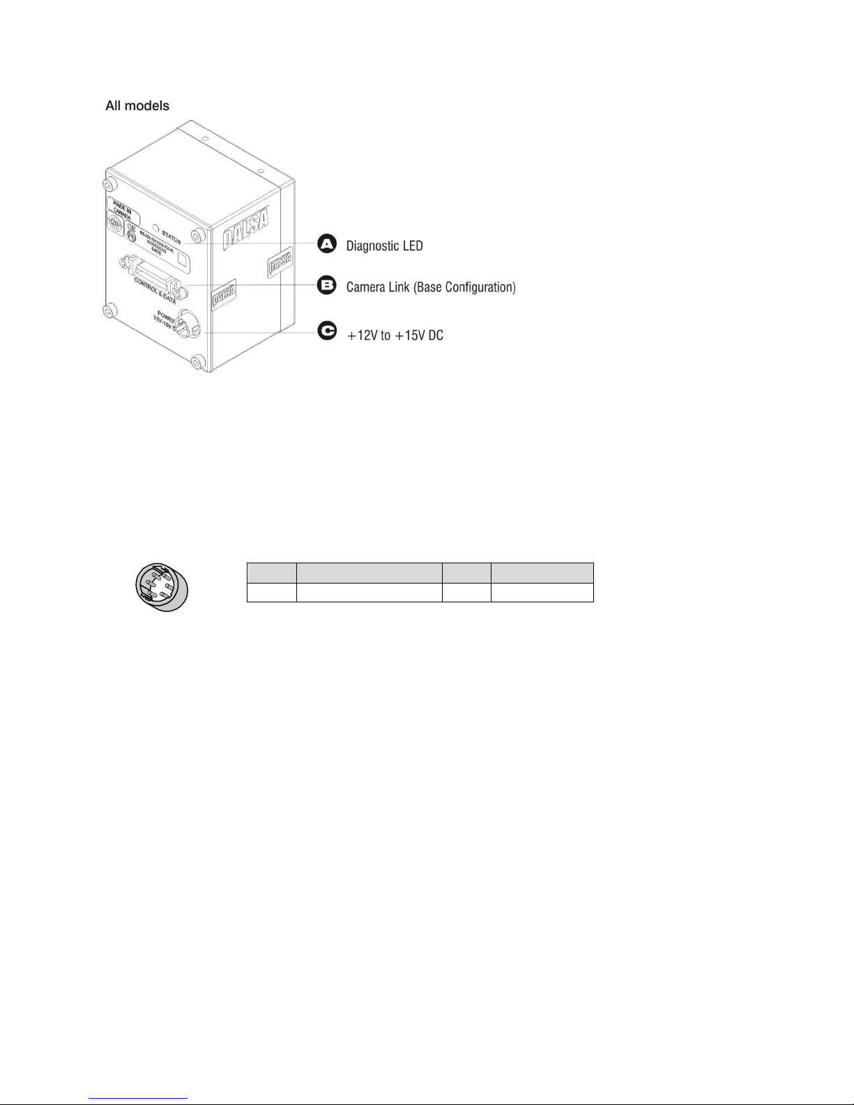
The camera uses:
A diagnostic LED for monitoring the camera.
High-density 26-pin MDR26 connector for Camera Link control signals, data signals, and serial
communications.
One 6-pin Hirose connector for power.
Teledyne DALSA 03-032-20116-01
16 Spyder3 SC-34 Color Camera User's Manual
Pin
Description
Pin
Description
1, 2, 3
Min +12 to Max +15V
4, 5, 6
Ground
Hirose 6-pin Circular Male
5
4
6
2
3
1
Mating Part: HIROSE
HR10A-7P-6S
Figure 7: Input and Output Connectors
WARNING: It is extremely important that you apply the appropriate voltages to your camera. Incorrect
voltages may damage the camera.
2.1 Power Connector
Figure 8: Hirose 6-pin Circular Male—Power Connector and Table 6: Hirose Pin Description
The camera requires a single voltage input (+12 to +15 V). The camera meets all performance
specifications using standard switching power supplies, although well-regulated linear supplies provide
optimum performance.
When settin g up the cam era’s pow er supplies follow these guide lines:
Apply the appropriate voltages. Ensure +12 V to +15 V at the camera power input (after the voltage
drop across the power cable). This may mean that the power supp ly will have to provide a voltage
greater than the required one, in order to adjust for this loss. For example, to achieve +12 V at the
camera, the power supply may need to supply +12.5 V or greater.
Protect the camera with a fast-blow fuse between power supply and camera.
Do not use the shield on a multi-conductor cable for ground.
Keep leads as short as possible to reduce voltage drop.
Use high-quality linear supplies to minimize noise.
Note: Camera performance specifications are not guaranteed if your power supply does not meet these requirements.
03-032-20116-01 Teledyne DALSA
Spyder3 SC-34 Color Camera User's Manual 17
Priority
Color of Status LED
Meaning
1
Flashing Red
Fatal Error. For example, camera temperature is too high and camera
thermal shutdown has occurred .
Warning. Loss of functionality (e.g. external SRAM failure).
2
Flashing Green
Camera initialization or executing a long command
3
Solid Green
Camera is operational and functioning correctly
4
Solid Red
Warning. Loss of functionality.
Configuration
8 Bit Ports
Supported
Serializer
Bit Width
Number
of Chips
Number of
MDR26
Connectors
Applicable
Camera
Models
Base
A, B, C
28 1 1
All models
Base Configuration
One Channel Link Chip + Camera Control + Serial Communication
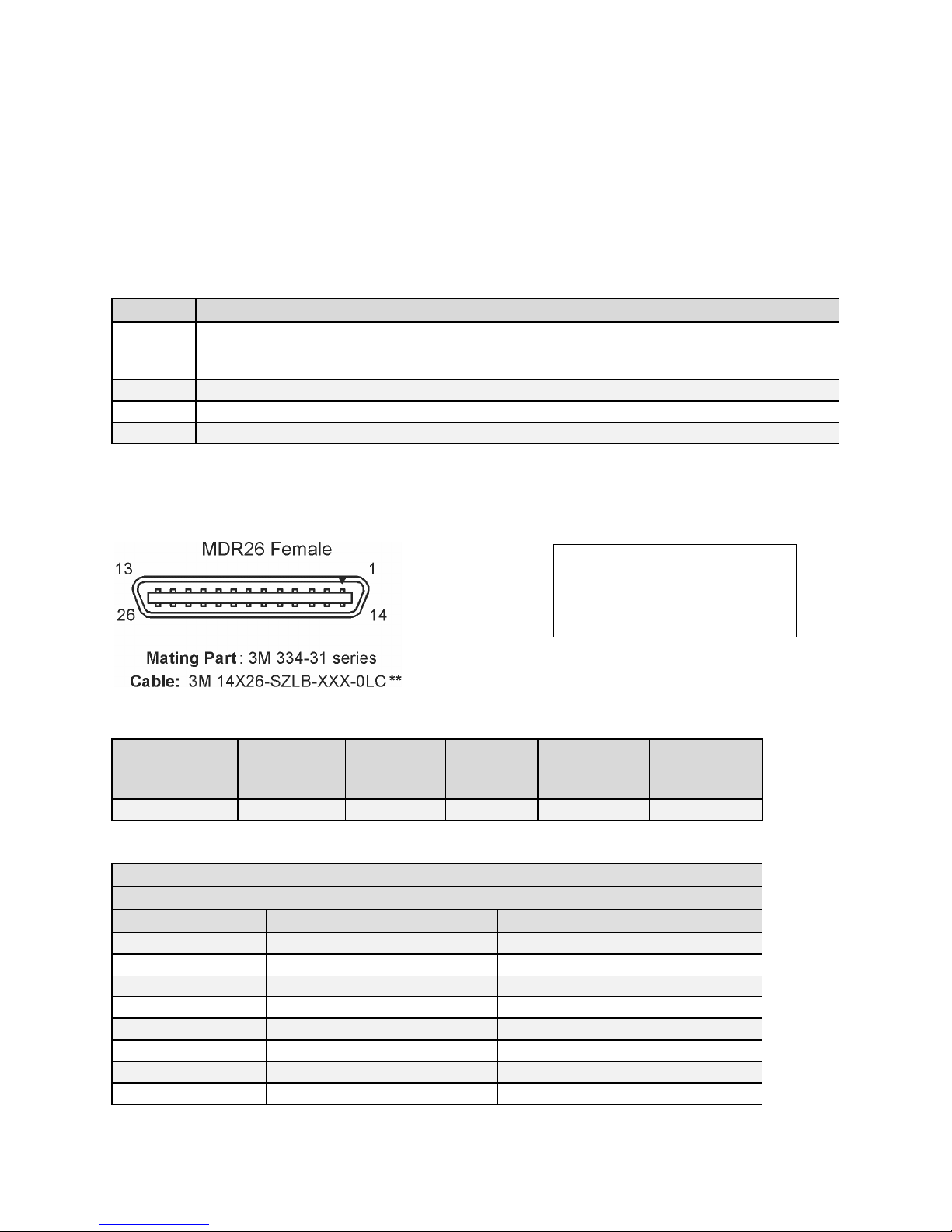
Camera Connector
Right Angle Frame Grabber
Channel Link Signal
1 1 inner shield
14
14
inner shield
2
25
X0-
15
12
X0+
3
24
X1-
16
11
X1+
4
23
X2-
17
10
X2+
**3M part 14X26-SZLB-XXX-0LC is a complete
cable assembly, including connectors.
Unused pairs should be terminated in 100
ohms at both ends of the cable.
2.2 Camera LED
The camera is equipped with a red/ green LED used to display the operational status of the camera. The
table below summarizes the operating states of the camera and the corresponding LED states.
When more than one condition is active, the LED indicates the cond ition with the highest priority. Error
and warning states are accompanied by corresponding messages further describing the current camera
status.
Table 7: Diagnostic LED
2.3 Camera Link Data Connector
Figure 9: Camera Link MDR26 Connector
The Camera Link interface is implemented as Base Configuration in the Spyder3 Color cameras.
Table 8: Camera Link Hardware Configuration Summary
Table 9: Camera Link Connector Pinout
Teledyne DALSA 03-032-20116-01

18 Spyder3 SC-34 Color Camera User's Manual
5
22
Xclk-
18 9 Xclk+
6
21
X3-
19
8
X3+
7
20
SerTC+
20 7 SerTC-
8
19
SerTFG-
21 6 SerTFG+
9
18
CC1-
22 5 CC1+
10
17
CC2+
23 4 CC2-
11
16
CC3-
24 3 CC3+
12
15
CC4+
25 2 CC4-
13
13
inner shield
26
26
inner shield
Signal
Configuration
CC1
EXSYNC
CC2
PRIN
CC3
Direction
Notes:
*Exterior Overshield is connected to the shells of the connectors on both ends.
**3M part 14X26-SZLB-XXX-0LC is a complete cable assembly, including connectors.
Unused pairs should be terminated in 100 ohms at both ends of the cable.
Inner shield is connected to signal ground inside camera
Table 10: Camera Control Configuration
See Appendix B for the complete Camera Link configuration table, and refer to the Teledyne DALSA Web
site for the official Camera Link documents
(http:/ / www.teledynedalsa.com/ mv/ knowledge/ appnotes.aspx).
Input Signals, Camera Link
The camera accepts control inputs through the Camera Link MDR26F connector.
The camera ships in internal sync, maximum exposure time (exposure mode 7).
EXSYNC (Triggers Line Readout)
Line rate can be set internally using the serial interface. The external control signal EXSYNC is optional
and enabled through the serial interface. This camera uses the falling edge of EXSYNC to trigger pixel
readout. See Setting the Exposure Mode, page 27, for details on how to set line rates, exposure times, and
camera modes.
03-032-20116-01 Teledyne DALSA
Spyder3 SC-34 Color Camera User's Manual 19
Clocking Signal
Indicates
LVAL (high)
Outputting valid line
DVAL (high)
Valid data (unused, tied high)
STROBE (rising edge)
Valid data
FVAL (high)
Outputting valid frame (unused, tied high)
Output Signals, Camera Link
These signals indicate when data is valid, allowing you to clock the data from the camera to your
acquisition system. These signals are part of the Camera Link configuration and you should refer to the
Camera Link Implementation Road Map for the standard location of these signals
(http:/ / www.teledynedalsa.com/ mv/ knowledge/ appnotes.aspx).
The cam era inter n ally d igitizes 12 bits and ou tp uts th e 8 MSB or all 12 bits d ep en d ing on th e cam era‘s
Camera Link operating mode.
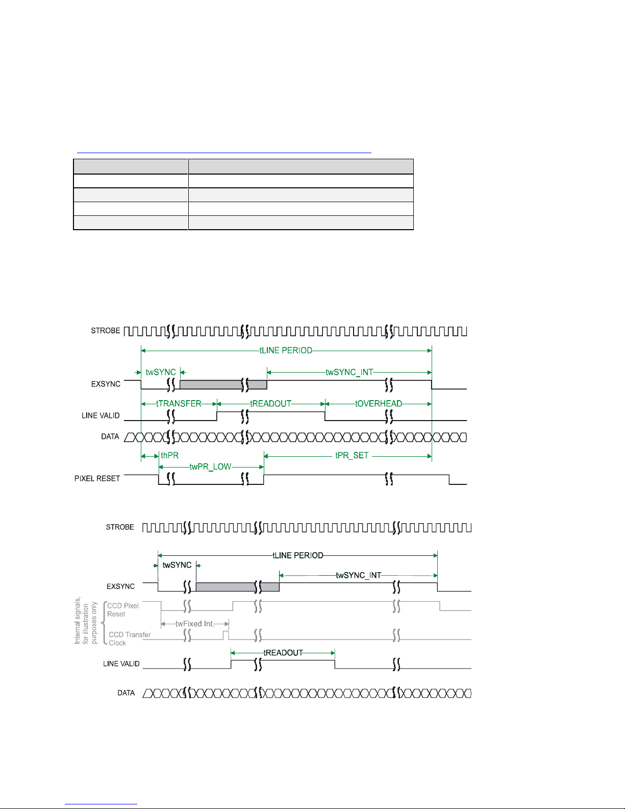
2.4 Camera Link Video Timing
Figure 10: Overview Timing Showing Input and Output Relationships
Figure 11: Fixed (Programmed) Integration Timing with External EXSYNC
Teledyne DALSA 03-032-20116-01
20 Spyder3 SC-34 Color Camera User's Manual
Symbol
Definition
Min (ns)
twSYNC
The minimum low width of the EXSYNC pulse when not in SMART
EXSYNC mode.
100
twSYNC
(SMART)
*
The minimum low width of the EXSYNC pulse when in SMART EXSYNC
mod es to guarantee the photosites are reset.
3,000
twSYNC_INT
The m inim u m w id th of th e high p u lse w h en th e ―SMART EXSYNC‖
feature is turned off
100
twSYNC_INT
(SMART)
*
Is the in teg ration tim e w h en th e ―SMART EXSYN C‖ featu re is a vailable
and turned on. Note that the minimum time is necessary to guarantee
proper operation.
3,000
tLINE PERIOD
(t LP)
The minimum and maximum line times made up of tTransfer,
tREADOUT plus tOVERHEAD to meet specifications.
55,550 (2k 2 tap)
11,1100 (4k 2 tap)
tTransfer
The time from the reception of the falling edge of EXSYNC to the rising
edge of LVAL when pretrigger is set to zero. Pretrigger reduces the
num ber of clocks to the r isin g ed ge of LVAL but doesn‘t chan g e th e tim e
to the first valid pixel. If the fixed integration time mode of operation is
available and selected then the integration time is added to the specified
value.
1, 450 ±50 (2k)
1, 650 ±50 (4k)
twFixed Int.
Fixed Integration Time mode of operation for variable exsync frequency.
800
tREADOUT
Is the number of pixels per tap times the readout clock period .
52,975 (2k 2 tap)
104,275 (4k 2 tap)
tOVERHEAD
Is the number of pixels that must elapse after the falling ed ge of LVAL
before the EXSYNC signal can be asserted. This time is used to clamp the
internal analog electronics
50 ±12 (2k)
210 ±12 (4k)
twPR_LOW
Minimum Low time to assure complete photosite reset
3,000
tPR_SET
The nominal time that the photo sites are integrating. Clock
synchronization w ill lead to integration time jitter, which is shown in the
specification as +/ - values. The user should command times greater than
these to ensure proper charge transfer from the photosites. Failure to
meet this requirement may result in blooming in the Horizontal Shift
Register.
3,000
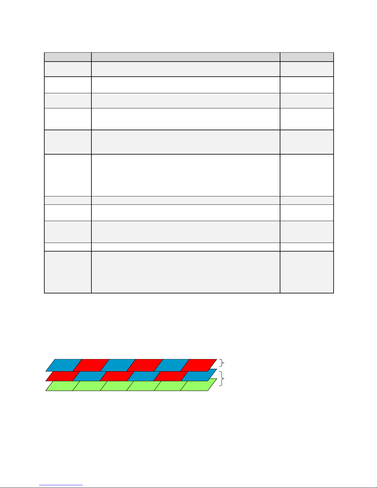
G21 G25G23 G24G22 G26G21 G25G23 G24G22 G26
R11 B12 B16B14 R15R13
B_in R_in
Interpolated
Native
Table 11: Spyder3 Color Input and Output
Camera Output Format
There are several color output formats:
RGB mode (interpolation): camera outputs three colors (two native colors, one interpolated color) for
each pixel.
RG/ BG mode (native): In this mode the camera outputs two native colors per pixel, (RG or BG depending
on the pixel location)
G mode (native): This mode provides 100% fill factor native green color that can be used as a
monochrome channel
03-032-20116-01 Teledyne DALSA

Spyder3 SC-34 Color Camera User's Manual 21
Step 3. Establish Communication with the
Camera
Power on the camera
Turn on the cam er a‘s p ow er sup ply. You m ay h av e to w ait u p to 60 second s w hile th e cam era w ar m s u p
and prepares itself for operation.
Connect to the camera
In order for you to communicate with the camera, a serial connection in the Camera Link cable needs to
be established. The frame grabber manufacturers should be able to provide a solution in order to
communicate through this serial link. Terminal software can also be provided by the frame grabber
manufacturer. Standard terminal software, such as Microsoft HyperTerminal, can be used if the COM
port is allocated by the frame grabber. Start your GUI and establish communication with the camera.
Check LED Status
If the camera is operating correctly at this point, the diagnostic LED will flash for 10 seconds and then
turn solid green.
Software Interface
All the camera features can be controlled through the ASCII serial interface.
Teledyne DALSA 03-032-20116-01

22 Spyder3 SC-34 Color Camera User's Manual
3.1 Using Camera Link with Spyder3 Cameras
All of the camera features can be controlled through the serial interface. The camera can also be used
without the serial interface after it has been set up correctly. For example, functions available include:
Controlling basic camera functions such as gain and sync signal source.
Flat field correction.
Mirroring and readout control
Generating a test pattern for debugging.
The serial interface uses a simple ASCII-based protocol and the PC does not require any custom software.
Note: This command set may be different from those used by other Teledyne DALSA cameras. You
should not assume that these commands perform the same as those for older cameras.
Complete Command List
A complete list of the ASCII commands and their parameters is available here.
Serial Protocol Defaults
8 data bits
1 stop bit
No parity
No flow control
9.6kbps
Camera does not echo characters
Command Format
The camera responds to a simple ASCII-based protocol. When entering commands, remember that:
A carriage return <CR> ends each command.
A space or multiple space characters separate parameters. Tabs or commas are invalid parameter
separators.
Upper and lowercase characters are accepted
The backspace key is supported
The cam era w ill answ er each com mand w ith either <CR><LF> ―OK >" or <CR><LF>"Error xx: Error
Message >" or ―War n ing xx: Warnin g Messag e >‖ . The ">" is u sed exclu siv ely as th e last ch ar acter
sent by the camera.
The following parameter conventions are used in the manual:
• i = integer value
• f = real number
• m = member of a set
• s = string
• t = tap id
• x = pixel column number
• y = pixel row number
Example: to return the current camera settings
gcp <CR>
03-032-20116-01 Teledyne DALSA

Spyder3 SC-34 Color Camera User's Manual 23
Purpose:
Sets the speed in bps of the serial communication port.
Syntax:
sbr m
Syntax Elements:
m
Baud rate. Available baud rates are: 9600 (Default), 19200,
57600, and 115200.
Notes:
Power-on rate is alw ays 9600 baud.
The rc (reset camera) command will not reset the camera to the
pow er-on baud rate and will reboot using the last used baud rate.
Example:
sbr 57600
Camera Help Screen
For quick help, the camera can return all available commands and parameters through the serial
interface.
There are two different help screens available. One lists all of the available commands to configure
camera operation. The other help screen lists all of the commands available for retrieving camera
parameters (these are called ―get‖ com m and s).
To view the help screen listing all of the camera configur ation commands, use the command h.
To view a help screen listing all of the ―get‖ com m and s, u se th e comm and gh.
The camera configuration command help screen lists all commands available. Parameter ranges
displayed are the extreme ranges available. Depending on the current camera operating conditions, you
may not be able to obtain these values. If this occurs, values are clipped and the camera returns a warning
message.
Some commands may not be available in your current operating mode. The help screen displays NA in
this case.
Baud Rate
3.2 First Power Up Camera Settings
When the camera is powered up for the first time, it operates using the following factory settings:
Forward CCD shift direction
RGB color output mode (clm 5)
Exposure mode 7 (Programmable line rate & max exposure time, 625 µs)
1600 Hz line rate
Readout mode: Auto
Mirroring mode: 0, left to right
Factory calibrated analog gain and offset
8 bit output
Teledyne DALSA 03-032-20116-01
24 Spyder3 SC-34 Color Camera User's Manual
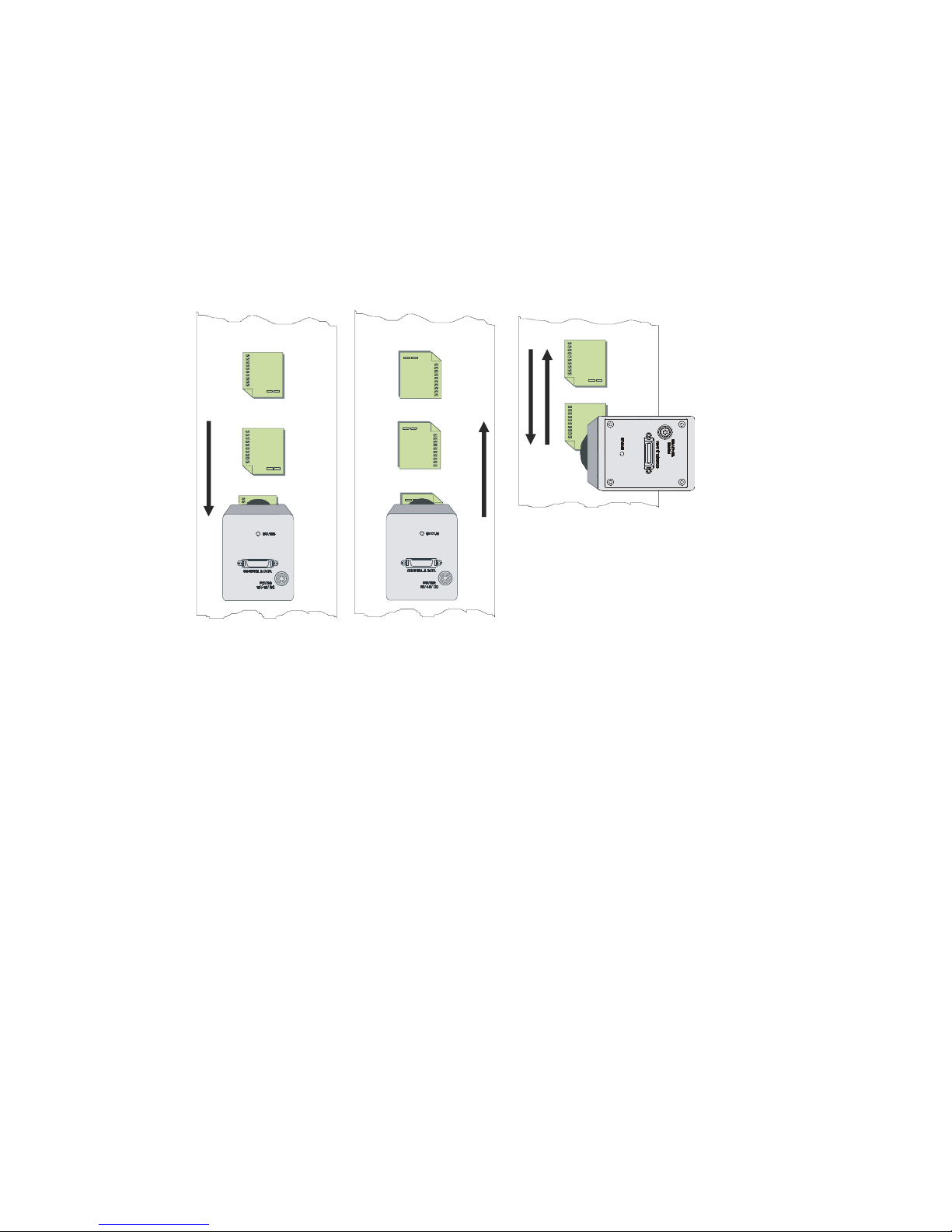
4k camera orientation
Camera should operate in
reverse shift direction
scd 1
Camera should operate in
forward shift direction
scd 0
Arrows denote
direction of
object movement
3.3 Sensor Output Format
Sensor Shift Direction
You can select either forward or reverse CCD shift direction. This accommodates object direction change
on a w eb and allow s y ou t o m ou nt the camera ― u psid e d ow n .‖ The scan direction has no effect on the
color output format.
Figure 12: Object Movement and Camera Direction Example using an Inverting Lens
Note: You can control the CCD shift direction through the serial interface. Use the software command scd
to determine whether the direction control is set via software control or via the Camera Link control
signal on CC3. Refer to the CCD Shift Direction section of this manual, page 24, for details.
03-032-20116-01 Teledyne DALSA
 Loading...