

1-Feb-12
03-032-20123-00
www.teledynedalsa.com
Spyder3
SG-14 Camera User’s Manual

2 Spyder3 GigE Vision SG-14 Cameras User’s Manual
North America
605 McMurray Rd
Waterloo, ON N2V 2E9
Canada
Tel: 519 886 6000
Fax: 519 886 8023
www.teledynedalsa.com
sales.americas@teledynedalsa.com
support@teledynedalsa.com
Europe
Breslauer Str. 34
D-82194 Gröbenzell (Munich)
Germany
Tel: +49 - 8142 – 46770
Fax: +49 - 8142 – 467746
www. teledynedalsa.com
sales.europe@teledynedalsa.com
support@teledynedalsa.com
Asia Pacific
Ikebukuro East 13F
3-4-3 Higashi-Ikebukuro
Toshima-ku, Tokyo 170-0013
Japan
Tel: 81 3 5960 6353
Fax: 81 3 5960 6354 (fax)
www.teledynedalsa.com
sales.asia@teledynedalsa.com
support@teledynedalsa.com
© 2012 Teled yne DALSA Inc. All information provided in this manual is believed to be accurate and reliable. No responsibility is
assumed by Teledyne DALSA for its use. Teledyne DALSA reserves the right to make changes to this information without notice.
Reproduction of this manual in whole or in part, by any means, is prohibited without prior permission having been obtained from
Teled yne DALSA.
About Teledyne Technologies and Teledyne DALSA, Inc.
Teled yne Technologies is a leading provid er of sophisticated electronic subsystems, instrumentation and communication products,
en gin eered systems, aero sp a ce en gine s, and energy an d p ow er ge nera tio n systems. Teledyn e Techn ologies’ op erations ar e p rimar i ly
located in the United States, the United Kingdom and Mexico. For more information, visit Teled yne Tech nologies’ website a t
www.teledyne.com.
Teled yne DALSA, a Teledyne Technologies company, is an international leader in high performance digital imaging and
semiconductors with approximately 1,000 employees worldwide, headquartered in Waterloo, Ontario, Canad a. Established in 1980,
the company designs, develops, manufactures and markets digital imaging products and solutions, in addition to providing MEMS
products an d serv ices. For mo re information , visit Teled yne DA LSA’s w ebsite at w w w .teled ynedalsa.com.
Support
For further information not included in this manual, or for information on Teledyne DALSA’s extensive lin e of imag e sensing
products, please contact:
Industry Standards
Spyder GEV cameras are 100% compliant with the GigE Vision 1.0 specification. This specification defines
the communication interface protocol used by GigE Vision devices. For more information on these
requirements refer to the following site:
http:/ / www.machinevisiononline.org/ public/ articles/ details.cfm?id=2761
Spyder GEV cameras implement a superset of the GenICam ™ specification which defines device
capabilities. This description takes the form of an XML device description file respecting the syntax
defined by the GenApi module of the GenICam specification. For more information on these
requirements refer to the following site: www.genicam.org.
03-032-20123-00 Teledyne DALSA

Spyder3 GigE Vision SG-14 Cameras User’s Manual 3
Contents
The Spyder3 SG-14 Cameras ________________________________________________________________________ 6
Camera Highlights ............................................................................................................................................................. 6
Camera Performance Specifications .................................................................................................................................. 7
Certifications ...................................................................................................................................................................... 10
Responsivity ....................................................................................................................................................................... 11
Mechanicals ........................................................................................................................................................................ 12
Mounting ......................................................................................................................................................... 13
Image Sensor ..................................................................................................................................................................... 14
Software and Hardware Setup .......................................................................................................................................... 15
Host System Requirements ............................................................................................................................. 15
Network Adapter Requirements ..................................................................................................................... 15
Ethernet Switch Requirements ........................................................................................................................ 15
Setup Steps: Overview ....................................................................................................................................................... 15
1. Install and Configure Ethernet Network Card ............................................................................................. 15
2. Connect Power, Ethernet and I/O Cables .................................................................................................... 16
3. Establish communicating with the camera .................................................................................................. 16
4. Check camera LED, settings and test pattern .............................................................................................. 16
5. Operate the Camera ................................................................................................................................... 16
Step 1. Ethernet Network Card: Install and Configure ...................................................................................................... 17
Install Network Card ....................................................................................................................................... 17
Configure Network Card ................................................................................................................................. 17
Step 2. Connect Power, Ethernet, and Trigger Cables ....................................................................................................... 20
Power Connector ............................................................................................................................................. 20
Ethernet Connector and Ethernet LED ............................................................................................................ 21
Status LED ....................................................................................................................................................... 21
GPIO Connector: External Input ..................................................................................................................... 22
GPIO Isolation................................................................................................................................................. 22
GPIO Configuration ........................................................................................................................................ 22
TTL Inputs and Outputs................................................................................................................................... 23
Step 3. Establish Communication with the Camera ........................................................................................................... 24
Power on the camera ...................................................................................................................................... 24
Connect to the camera .................................................................................................................................... 24
Check LED Status ............................................................................................................................................ 24
Software Interface ........................................................................................................................................... 24
Using Sapera CamExpert with Spyder3 Cameras .............................................................................................................. 25
CamExpert Panes ............................................................................................................................................ 26
Step 4. Camera Settings and Test Patterns ....................................................................................................................... 28
Review a Test Pattern Image .......................................................................................................................... 28
Camera Operation _______________________________________________________________________________ 29
Factory Settings ................................................................................................................................................................. 29
Check Camera and Sensor Information ............................................................................................................................. 30
Verify Temperature and Voltage ....................................................................................................................................... 30
Saving and Restoring Camera Settings ............................................................................................................................. 31
Teledyne DALSA 03-032-20123-00

4 Spyder3 GigE Vision SG-14 Cameras User’s Manual
Timing: Exposure and Synchronization ............................................................................................................................. 33
Timing ............................................................................................................................................................. 34
Exposure Controls .............................................................................................................................................................. 35
Set the Exposure Mode.................................................................................................................................... 35
Exposure Modes in Detail ............................................................................................................................... 36
Line Rate ........................................................................................................................................................................... 37
Exposure Time ................................................................................................................................................................... 38
Triggers.............................................................................................................................................................................. 38
Input / Output Control ....................................................................................................................................................... 39
Gain, Black Level, and Background .................................................................................................................................. 40
Image Size ......................................................................................................................................................................... 41
Pixel Format ...................................................................................................................................................................... 42
Sensitivity Mode ................................................................................................................................................................. 42
Sensor Direction Control .................................................................................................................................................... 42
Sensor Shift Direction ..................................................................................................................................... 43
Binning .............................................................................................................................................................................. 44
Resetting the Camera ........................................................................................................................................................ 44
Camera Calibration_______________________________________________________________________________ 45
Processing Chain Overview and Description ................................................................................................... 45
Analog Gain and Offset Adjustment .................................................................................................................................. 47
Calibrate the Camera to Remove Non-Uniformity (Flat Field Correction) ........................................................................ 49
Digital Signal Processing ................................................................................................................................ 51
Appendix A: Clear Dark Current ______________________________________________________________________ 55
Setting the Readout Mode .............................................................................................................................. 55
Appendix B: Sensitivity Mode ________________________________________________________________________ 62
Sensitivity Mode and Pixel Readout ............................................................................................................... 62
Appendix C: GPIO Control __________________________________________________________________________ 64
GPIO Getting Started: Beginner Mode .............................................................................................................................. 64
The GPIO Connector ........................................................................................................................................ 64
Configure GPIO Signal Levels ......................................................................................................................... 65
Examples: Setting the Camera Modes ............................................................................................................................... 66
Free Run Mode: Internal Line Trigger, Internal Direction Control, Internal frame trigger ........................... 66
Internal Line Trigger, External Direction Control, Internal frame trigger...................................................... 68
External Line Trigger, Internal Direction Control, Internal frame trigger...................................................... 69
External Line Trigger, External Direction Control from Rotary Encoder......................................................... 70
External Frame Trigger: Frame Start Trigger mode ..................................................................................... 72
Outputs .............................................................................................................................................................................. 75
Trigger Settings: GURU Mode ........................................................................................................................................... 77
Pulse Generator .............................................................................................................................................. 80
Rescaler ........................................................................................................................................................... 82
Counter ........................................................................................................................................................... 84
Input Debouncing ........................................................................................................................................... 85
Timestamp Counter ......................................................................................................................................... 86
Delayer ........................................................................................................................................................... 88
PLC Control ........................................................................................................................................................................ 88
03-032-20123-00 Teledyne DALSA

Spyder3 GigE Vision SG-14 Cameras User’s Manual 5
The PLC Control Block ..................................................................................................................................... 89
GPIO Output Labels ........................................................................................................................................ 91
Signal Routing Block ......................................................................................................................................................... 93
How the Signal Routing Block Works ............................................................................................................. 94
How the Lookup Table Works ......................................................................................................................... 96
Appendix D: EMC Declaration ________________________________________________________________________ 97
Revision History _________________________________________________________________________________ 98
Index ________________________________________________________________________________________ 99
Teledyne DALSA 03-032-20123-00

6 Spyder3 GigE Vision SG-14 Cameras User’s Manual
The Spyder3 SG-14 Cameras
Camera Highlights
The Spyder3 SG-14 GigE Vision (GEV) are high sensitivity dual-line scan cameras. When operating in
high sensitivity (dual line scan) mode the Spyder3 GEV camera has 3x the responsivity of Teledyne
DALSA’s Sp yd er2 line scan cam era. Plus, the GigE Vision interface eliminates the need for a frame
grabber, resulting in significant system cost savings.
The Spyd er3 ca m eras ar e su pp orted by Teled yne DALSA Sap era™ softw are librar ies featu rin g
CamExpert for simplified camera set-up and configuration.
Features
Broadband responsivity up to 408 ±16 DN (nJ/ cm2) @ 10dB gain
1024, 2048, or 4096 x 2 pixels, 14 µm x 14 µm (1k and 2k) and 10 µm x 10 µm (4k) pixel pitch, 100 %
fill factor
High or low speed (40 or 80 MHz)
Up to 68 KHz line rates
Dynamic range up to 1400 : 1
Data transmission up to 100 meters
RoHS and CE compliant
GenICam-compliant
Programmable gain, offset, exposure time and line rate, trigger mode, test pattern output, and camera
diagnostics
Tall pixel, high sensitivity, or low sensitivity mode available
Flat-field correction—minimizes lens vignetting, non-uniform lighting, and sensor FPN and PRNU
Applications
FPD inspection
Pick and place
Container inspection
Wood / tile / steel inspection
100 % print inspection (lottery tickets, stamps, bank notes, pay checks)
Postal sorting
Glass bottle inspection
Industrial metrology
Food inspection
Web inspection
03-032-20123-00 Teledyne DALSA

Spyder3 GigE Vision SG-14 Cameras User’s Manual 7
Model Number
Description
SG-14-01K40-00-R
1k resolution, 1 sensor tap, 40 MHz d ata rate, 36 kHz line rate, RoHS compliant.
SG-14-01K80-00-R
1k resolution, 2 sensor taps, 80 MHz data rate, 68 kHz line rate, RoHS compliant.
SG-14-02K40-00-R
2k resolution, 1 sensor tap, 40 MHz d ata rate, 18.5 kHz line rate, RoHS compliant.
SG-14-02K80-00-R
2k resolution, 2 sensor taps, 80 MHz data rate, 36 kHz line rate, RoHS compliant.
SG-14-04k80-00-R
4k resolution, 2 sensor taps, 80 MHz data rate, 18.5 kHz line rate, RoHS compliant.
Software
Product Number / Version Number
Sapera LT, including CamExpert GUI
application
Version 7.1 or later. Tested and recommended.
QuickCam
Version 2.0. Compliant.
Pleora Technologies Inc.’s Coyote
Compliant.
Third party software. E.g. CVB and NI.
Compatible. Drivers need to be provided by the third party.
Feature / Specification
1k
2k
4k
Imager Format
dual line scan
dual line scan
dual line scan
Resolution
1024 x 2 pixels
2048 x 2 pixels
4096 x 2 pixels
Pixel Fill Factor
100 %
100 %
100 %
Pixel Size
14 µm x 14 µm
14 µm x 14 µm
10 µm x 10 µm
Output Format (# of taps)
1 or 2
depending on
model
1 or 2 depending
on model
2
Sensitivity Mode
High, low, or tall
pixel
High, low, or tall
pixel
High, low, or tall pixel
Antiblooming
100x
100x
100x
Gain Range
-10 dB to +10 dB
-10 dB to +10 dB
Not available. Calibrated at 0 dB.
Speed
1k
2k
4k
Minimum Internal Line Rate
300 Hz
300 Hz
300 Hz
Maximum Line Rate
80 MHz model
68 kHz
36 kHz
18.5 kHz
40 MHz model
36 kHz
18.5 kHz
NA
Data Rate
40 or 80 MHz
40 or 80 MHz
80 MHZ
Optical Interface
Back Focal Distance
6.56 ± 0.25 mm
Lens Mounts
M42 x 1, C and F (1k and 2k)
M58 x 0.75, F (4k)
Models
The Spyder3 SG-14 camera is available in the following configurations:
Table 1: Camera Models Overview
Table 2: Software
Camera Performance Specifications
Table 3: Camera Performance Specifications
Teledyne DALSA 03-032-20123-00

8 Spyder3 GigE Vision SG-14 Cameras User’s Manual
Feature / Specification
1k
2k
4k
Sensor Alignment
x
y
z
z
±50 µm
±50 µm
±0.25 mm
±0.2°
Mechanical Interface
1k and 2k
4k
Camera Size
72 mm x 60 mm x 65 mm, all models
Mass
< 300 g
Connectors
power connector
GigE connector
GPI/ O connector
6 pin male Hirose
RJ45
High density 15-pin dsub
Electrical Interface
Input Voltage
+12 V to +15 V
Power Dissipation
< 9 W
< 9 W (4k)
Operating Temperature
0 °C to 65 °C
Bit Wid th
8 or 12 bit, user selectable
Output Data Configuration
GigE Vision
Specifications
Unit
-10 dB
0 dB
+10 dB
Min
Typ
Max
Min
Typ
Max
Min
Typ
Max
Broadband
responsivity
DN/ (nJ/ cm²)
1k and 2k Dual line
652.8
2064
6528
1k and 2k Single line
326.4
1032
3264
4k Dual line
431
1363
4k Single line
216
682
Random noise rms
DN 1k and 2k
3
6.5 9.2
20.5 30
65
4k 10
24
Dynamic range
DN:DN
1k and 2k Dual line
500:1
1400:1
203:1
324:1
59:1
108:1
1k and 2k Single line
500:1
1400:1
203:1
324:1
59:1
108:1
4k Dual and Single
1225:1
387:1
FPN global
DN p-p
Uncorrected
52.8
169.6
536
Corrected
32
32
64
PRNU ECD
Uncorrected local
%
8.5
8.5
11.5
Uncorrected global
%
10
10
10
Corrected local
DN p-p
80
80
95
Corrected global
DN p-p
80
80
95
4k Dual and Single
Corrected local
DN p-p
32
32
Corrected global
DN p-p
80
80
Uncorrected local
%
9.5
9.5
Table 4: Camera Operating Specifications
03-032-20123-00 Teledyne DALSA

Spyder3 GigE Vision SG-14 Cameras User’s Manual 9
Uncorrected
global
%
20
20
PRNU ECE
Uncorrected local
%
8.5
12
37
Uncorrected global
%
10
12
37
Corrected local
DN p-p
80
237
752
Corrected global
DN p-p
80
208
752
4k Dual and Single
Corrected local
DN p-p
237
237 Corrected global
DN p-p
237
237
Uncorrected local
%
9.5
9.5
Uncorrected global
%
20
20
SEE (calculated)
nJ/ cm²
1k and 2k Dual line
6.35
1.92
0.61 1k and 2k Single line
12.2
4.0
1.2
4k Dual line
9.2
2.9
4k Single line
18.0
5.7
NEE (calculated)
pJ/ cm²
Dual line
4.6
4.5
4.6
Single line
9.2
9.3
9.2
4k Dual line
7.0
8.1
4k Single line
14.0
16.1
Saturation output
amplitude
DN
3968±80
DC offset
DN
96
160
336
Teledyne DALSA 03-032-20123-00

10 Spyder3 GigE Vision SG-14 Cameras User’s Manual
Compliance
The CE Mark, FCC Part 15, and Industry Canada ICES-003 Evaluation of the DALSA Spyder GigE SG-14 cameras
meet the following requirements:
EN 55022 Class A, and EN 61326 Emissions Requirements, EN 55024, and EN 61326 Immunity to Disturbances
Test conditions unless otherwise noted:
12-bit values, Flat Field Correction (FFC) enabled.
CCD Pixel Rate: 40 MHz per sensor tap
Line Rate: 5000 Hz
Nominal Gain setting unless otherwise specified
Light Source: Broadband Quartz Halogen, 3250k, with 750 nm high-pass filter installed
Ambient test temperature 25 °C
Unless specified, all values are referenced at 12 bit
Exposure mode disabled.
Unless specified, dual line mode.
Note: PRNU measured at 50% SAT.
Certifications
Table 5: EMC Compliance Standards
03-032-20123-00 Teledyne DALSA
Spyder3 GigE Vision SG-14 Cameras User’s Manual 11
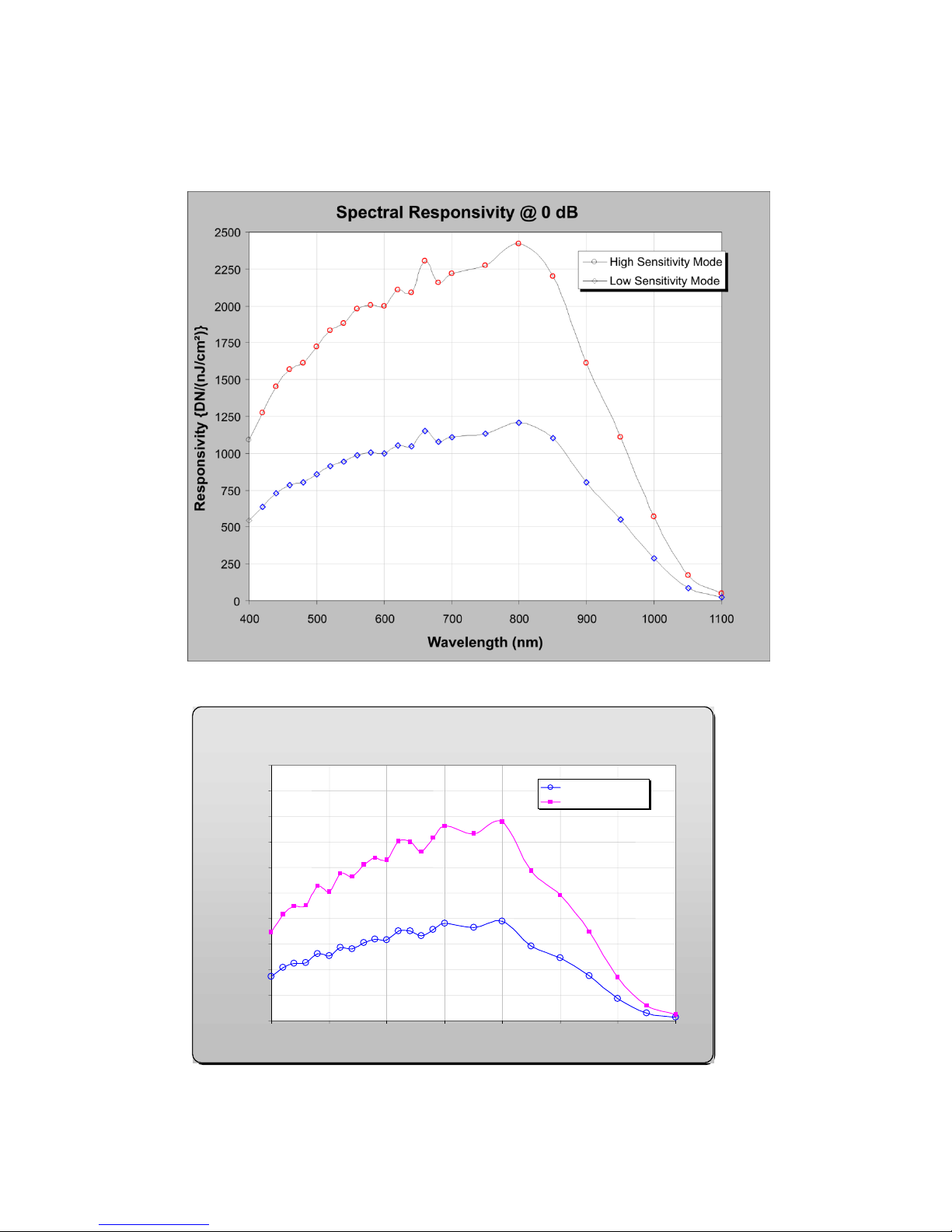
Spectral Responsivity @ 0 dB Gain
0
200
400
600
800
1000
1200
1400
1600
1800
2000
400
500
600
700
800
900
1000
1100
Wavelength (nm)
Low Sensitivity Mode
Hi Sensitivity Mode
12 bits DN/nJ/cm Responsivity
2
Responsivity
Figure 1: Spyder3 GigE Vision 1k and 2k Responsivity
Figure 2: Spyder3 GigE Vision 4k Responsivity
Teledyne DALSA 03-032-20123-00

12 Spyder3 GigE Vision SG-14 Cameras User’s Manual
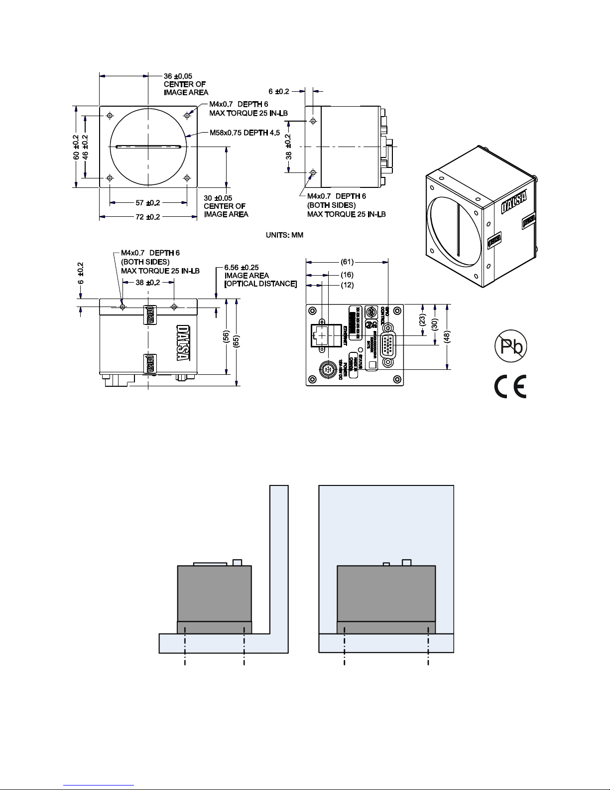
Mechanicals
Figure 3: Spyder3 1k and 2k GigE Vision Mechanical
03-032-20123-00 Teledyne DALSA
Spyder3 GigE Vision SG-14 Cameras User’s Manual 13
Figure 4: Spyder3 4k GigE Vision Mechanical
Mounting
Heat generated by the camera must be allowed to move away from the camera. Mount the camera on the
frontplate (using the provided mounting holes) with maximum contact to the area for best heat
dissipation.
Figure 5: Spyder3 Mounting Example
Teledyne DALSA 03-032-20123-00
14 Spyder3 GigE Vision SG-14 Cameras User’s Manual
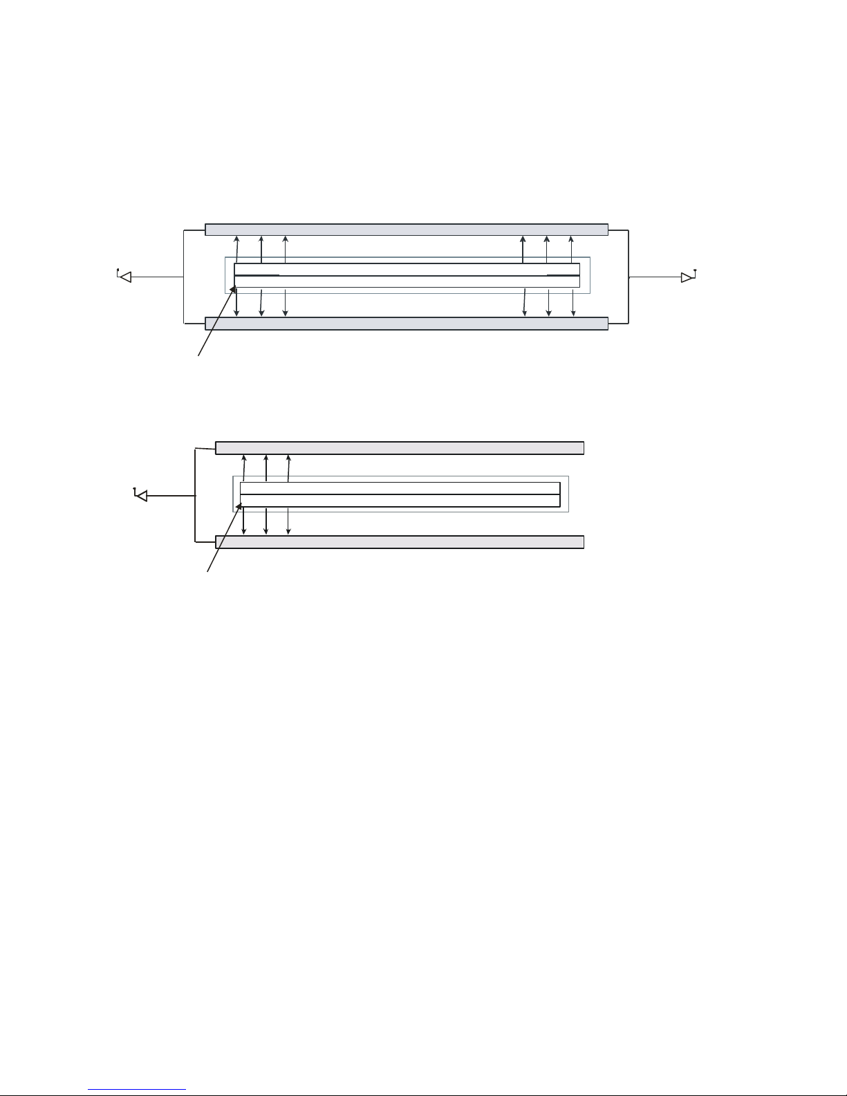
Tap 2Tap 1
CCD Readout Shift Register
CCD Readout Shift Register
N
Pixels
N
Pixels
N
=1024, 2048, 4096
Pixel 1, 1
Tap 1
CCD Readout Shift Register
CCD Readout Shift Register
N
Pixels (14µm x 14µm)
N
Pixels (14µm x 14µm)
N
=1024, 2048
Pixel 1, 1
Image Sensor
The cam era u ses Teled yne D ALSA’s d u al line scan sensor. Th e camer a can be configured to read out in
either high or low sensitivity mode, tall pixel mode and forward or reverse shift direction.
Figure 6: 2 Tap Sensor Block Diagram
Figure 7: 1 Tap Sensor Block Diagram (1k and 2k only)
03-032-20123-00 Teledyne DALSA

Spyder3 GigE Vision SG-14 Cameras User’s Manual 15
Software and Hardware Setup
Host System Requirements
To achieve best system performance, the following minimum requirements are recommended:
Operating system: Windows XP Professional, Windows Vista, Windows 7 (either 32-bit or 64-bit for
all) are supported.
Network Adapter Requirements
GigE network adapter (either PCI card or LOM): For high performance you must use a Intel
PRO/ 1000 MT ad apter.
The Spyder3 GEV camera works only with network adapters based on the Intel 82546, 82541, and 82540
network chips. The driver will also function with adapters based on the Intel 82544 chip, but these are not
recommended due to bugs in the chip that can cause control packets to be lost if sent while data is
streaming.
Ethernet Switch Requirements
When you require more than one device on the same network or a camera-to-PC separation of more than
100 metres, you can use an Ethernet switch. Since the Spyder3 GEV camera complies with the Internet
Protocol, the camera should work with all standard Ethernet switches. However, switches offer a range of
functions and performance grades, so care must be taken to choose the right switch for a particular
application.
Setup Steps: Overview
Take the following steps in order to setup and run your camera system. They are described briefly below
and in more detail in the following sections.
1. Install and Configure Ethernet Network Card
If your host computer does not have a Gigabit network adapter or equivalent (PCI bus Gigabit NIC)
already installed, then you need to install one.
For Gigabit performance we recommend the Intel PRO/ 1000 MT adapter, or equivalent. Follow the
manufactu rer’s installation instructions.
A GigE Vision compliant XML device description file is embedded within the cam era’s firmware
allowing GigE Vision compliant applications (e.g. Pleora`s Coyote, and SaperaLT) to recognize the
cam era’s cap abilities im mediately after connection. The Spyder3 camera was tested with and supports
SaperaLT which gives you access to the CamExpert GUI, a GigE Vision compliant application.
Software Installation
Install Sapera LT with CamExpert to control the Spyder3. You can access Sapera drivers, SDKs, and
demos from the following link: http:/ / www.teledynedalsa.com/ mv/ support/ driverSDKlist.aspx
Teledyne DALSA 03-032-20123-00

16 Spyder3 GigE Vision SG-14 Cameras User’s Manual
2. Connect Power, Ethernet and I/O Cables
Connect a power cable from the camera to a +12 VDC to +15 VDC power supply.
Connect the Ethernet cable from the camera to the computer Ethernet jack.
If using the external signals connect the external control cable to the camera.
3. Establish communicating with the camera
Start the GUI and establish communication with the camera.
4. Check camera LED, settings and test pattern
Ensure that the camera is operating properly by checking the LED, the current settings, and by acquiring
a test pattern.
5. Operate the Camera
At this point you will be ready to operate the camera in order to acquire and retrieve images, set camera
functions, and save settings.
03-032-20123-00 Teledyne DALSA
Spyder3 GigE Vision SG-14 Cameras User’s Manual 17
Step 1. Ethernet Network Card: Install and
Configure
Install Network Card
The following network card has been tested and is recommended for use with this camera: Intel Pro/ 1000
MT Desktop Adapter (33-MHz, 32-bit PCI). Order Code: PWLA8391GT (single packs). Follow the
manufactu rer’s recom mend ations t o install this card in the host PC.
Configure Network Card
The configuration shown here uses the Windows XP operating system as the host platform.
The camera communicates using the Ethernet connection and employs the static IP address: 192.168.5.100
(default). A static address ensures the fastest operation. Alternatively, you can use a dynamic IP address.
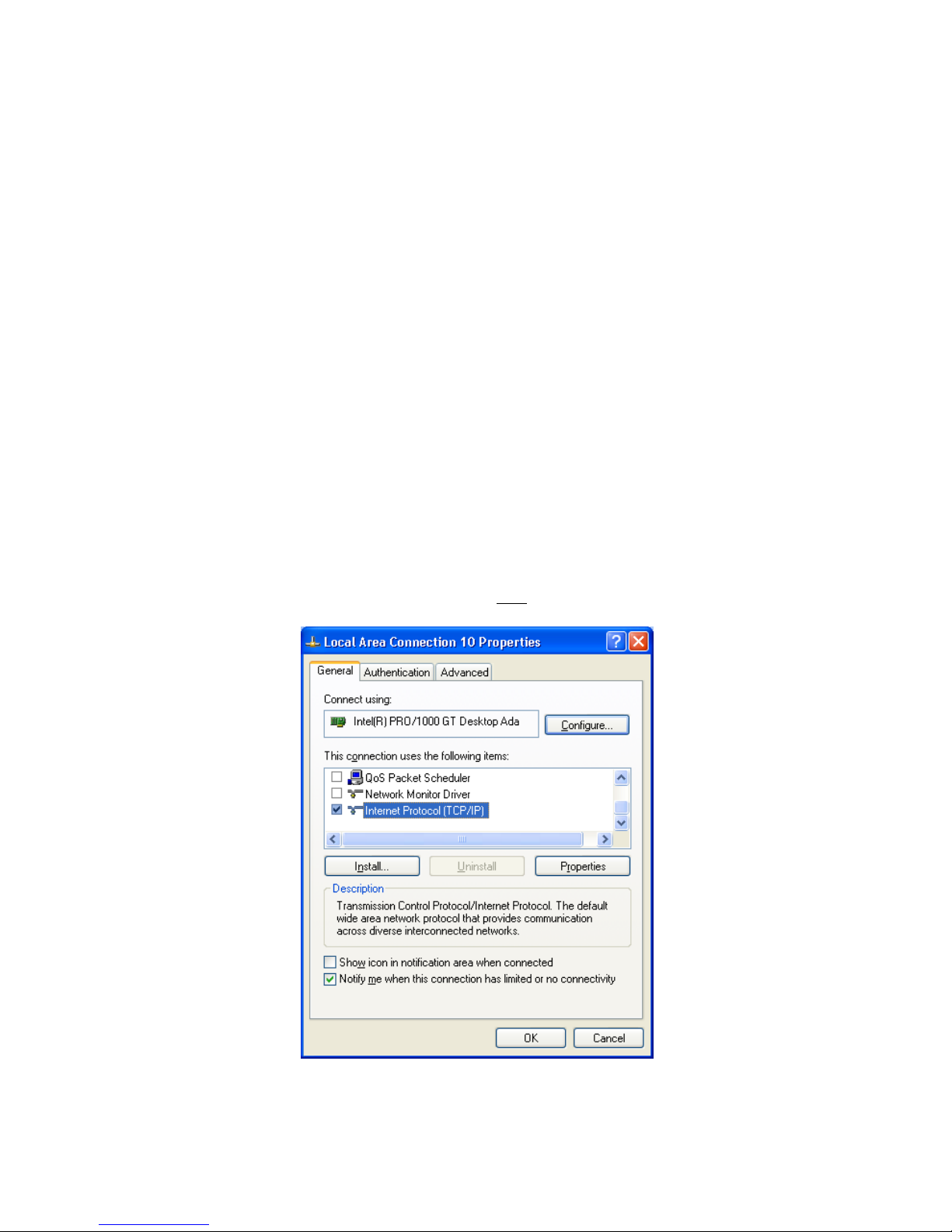
To configure the network card from the host PC:
1. In the Start menu under ―Control Panel‖ select ―Netw ork Connections,‖ and configure the
network card as follows:
2. Select the installed network card and click on ―Ch ange settin gs of this con n ectio n .‖
3. Enable the ―Intern et Prot ocol (TCP/ IP)‖ option only.
4. With ―Internet Pr otocol (TCP/ IP)‖ selected , click on the ―Prop erties‖ bu tton .
Teledyne DALSA 03-032-20123-00
Figure 8. Internet Protocol
18 Spyder3 GigE Vision SG-14 Cameras User’s Manual
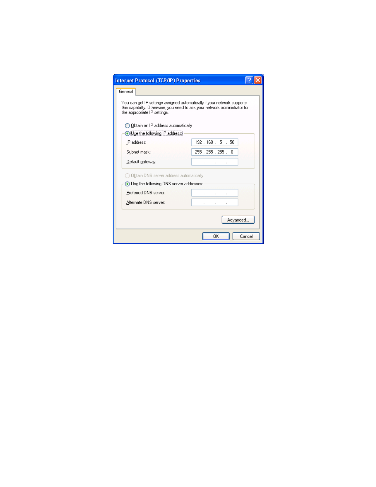
5. Select ―Use the follow in g IP add r ess‖ and set the IP address to an y address in this subnet other
than 192.168.5.100, which is used by the camera. In the example below, the address 192.168.5.50 is
used. Alternativ ely, select ―Obtain an IP ad d r ess au tom atically‖ to u se a d ynam ic add r ess.
6. Set subnet to: 255.255.255.0 an d click on ―OK.‖
Figure 9. IP Address
7. Click ―OK‖ t o save settin gs
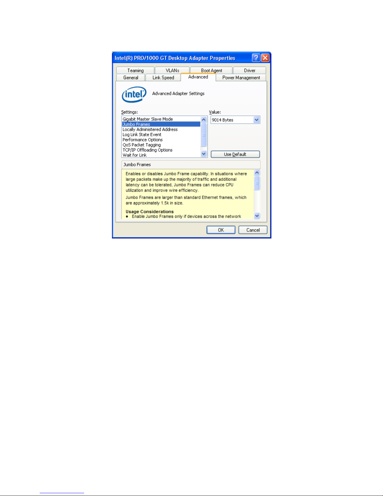
8. Click on ―C onfigure‖ button an d select ―A d van ced‖ ta b
9. Enable ―Jum bo Fram es‖ to greater th a n 9000 bytes. If your NIC does not support jumbo packets
the image transfer speed will be slower.
03-032-20123-00 Teledyne DALSA
Spyder3 GigE Vision SG-14 Cameras User’s Manual 19
10. Click ―OK‖ to save settin gs
Figure 10. Jumbo Frames
Teledyne DALSA 03-032-20123-00
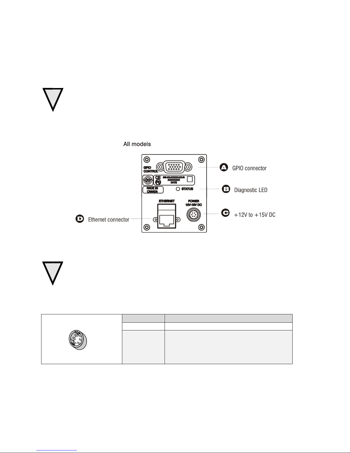
20 Spyder3 GigE Vision SG-14 Cameras User’s Manual
Pin
Description
1, 2, 3
Supply voltage—Min +12 VDC to Max +15 VDC
4, 5, 6
Ground
Hirose 6-pin Circular Male
5
4
6
2
3
1
Mating Part: HIROSE
HR10A-7P-6S
!
!
Step 2. Connect Power, Ethernet, and Trigger
Cables
WARNING! Grounding Instructions
Static electricity can damage electronic components. Please discharge any static electrical
charge by touching a grounded surface, such as the metal computer chassis, before performing
any hardware installation.
The use of cable types and lengths other than those specified may result in increased emission or
decreased immunity and performance of the camera.
Figure 11: Input and Output, trigger, and Power Connectors
Power Connector
WARNING: It is extremely important that you apply the appropriate voltages to your camera.
Incorrect voltages may damage the camera. Input voltage requirement: +12 V to +15 V DC.
The camera requires a single 6-pin Hirose connector with a single voltage input +12 VDC to +15 VDC for
power. The camera meets all performance specifications using standard switching power supplies,
although well-regulated linear supplies provide optimum performance.
Table 6. Hirose 6-Pin Power Pinout
03-032-20123-00 Teledyne DALSA

Spyder3 GigE Vision SG-14 Cameras User’s Manual 21
!
Priority
Color of Status LED
Meaning
1
Flashing Red
Fatal Error. For example, camera temperature is too high and
camera thermal shutdown has occurred.
2
Flashing Green
Camera initialization or executing a long command .
3
Solid Green
Camera is operational and functioning correctly.
Ethernet Connection
LED@ 1Gbps
Data Transmission LED
WARNING: When setting up the camera’s power supplies follow these guidelines:
Apply the appropriate voltages.
Protect the camera with a 2 amp slow-blow fuse between the power supply and the camera.
Do not use the shield on a multi-conductor cable for ground.
Keep leads as short as possible in order to reduce voltage drop.
Use high-quality linear supplies in order to minimize noise.
Note: If your power supply does not meet these requirements, then the camera performance specifications are not
guaranteed.
Ethernet Connector and Ethernet LED
The camera uses an RJ45 connector and a standard Cat 5 cable for Gigabit Ethernet signals and serial
communications. The device supports 10/ 100/ 1000 Mbit/ s speeds.
Note: Router connection not supported. Connection to a network switch for a single camera is supported.
Ethernet Connection LED
Steady ON indicates that an Ethernet connection is successfully established at 1Gbps.
Data Transmission LED
Steady ON indicates that the camera is ready for data transmission. Flashing indicates that the camera is
transmitting or receiving data.
EMC Compliance
In order to achieve EMC compliance, the Spyder3 camera requires the use of shielded CAT5e or CAT6
Ethernet cables.
Status LED
The camera is equipped with a red/ green LED used to display the status of the camera's operation. The
table below summarizes the operating states of the camera and the corresponding LED states.
When more than one condition is active, the LED indicates the condition with the highest priority. Error
and warning states are accompanied by corresponding messages that further describe the current camera
status.
Teledyne DALSA 03-032-20123-00
22 Spyder3 GigE Vision SG-14 Cameras User’s Manual
Pin
Signal
Description
GenICam Default
1
INPUT_ 0+
LVDS/TTL format (positive)
EXSYNC +
2
INPUT_0-
LVDS (negative)
EXSYNC -
3
INPUT_1+
LVDS/TTL format (positive)
FrameTrig +
4
INPUT_1-
LVDS (negative)
FrameTrig -
5
GND
6
INPUT_2+
LVDS/TTL format (positive)
Direction +
7
INPUT_2-
LVDS (negative)
Direction -
8
INPUT_3
TTL auxiliary input
9
OUTPUT_3
TTL auxiliary output
10
OUTPUT_2+
LVDS/TTL auxiliary output
11
OUTPUT_0+
LVDS/TTL auxiliary output
12
OUTPUT_0-
LVDS (negative)
13
OUTPUT_1+
LVDS/TTL auxiliary output
14
OUTPUT_1-
LVDS (negative)
15
OUTPUT_2-
LVDS (negative)
1
5
11
15
GPIO Connector: External Input
A single 15-pin general purpose input / output (GPIO) connector is used to receive or control external
signals. For example, the GPIO connector can be used to receive EXSYNC, PRIN (pixel reset), and
direction signals.
The GPIO connector is programmed through the GUI application. In CamExpert the relevant parameters
are located in the category Inputs Group.
Figure 12: GPIO Connector and Pin Numbers
Table 7: GPIO Connector Pinout
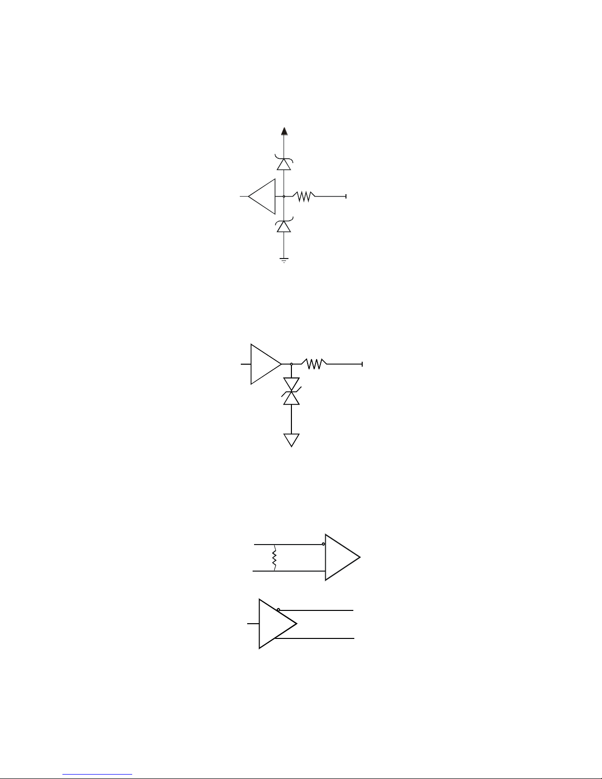
A schematic of the TTL input circuitry is shown in
Figure 13: TTL Input Schematic. The input signals are fed into the engine from external sources via the
GPIO connector.
GPIO Isolation
All of the GPIOs are isolated from the rest of the camera and the camera case. They are not isolated with
respect to each other and share a common return (ground) through pin 5 of the GPIO connector.
Note: The shell connection of the GPIO connector is not isolated and it should not be used as a return
(ground) for the GPIO signals. The shell connection is attached to the camera case.
GPIO Configuration
Refer to Appendix C: GPIO Control for a detailed description of the GPIO use-cases and configuration
options.
03-032-20123-00 Teledyne DALSA
Spyder3 GigE Vision SG-14 Cameras User’s Manual 23
1000
3.3V
3.3V
TTL
100
ESD
Protection
5V
100
TTL Inputs and Outputs
Figure 13: TTL Input Schematic
Termination: 1000 Ω series
Input current: minimum 0 nA; maximum 2 mA
Input voltage: maximum of low 0.66 V; minimum of high 2.6 V
TTL inputs are maximum 5 V and 3.3 V logic tolerant
Figure 14: TTL Output Schematic
Termination: 100 Ω series
Output current: sink 50 mA; source 50 mA
Output voltage: maximum of low 0.55 V @ 32mA; minimum of high 3.8 V @ 32mA.
LVDS Inputs and Outputs (LVDS compliant)
Figure 15: LVDS Input
Figure 16Figure 17: LVDS Output
Teledyne DALSA 03-032-20123-00

24 Spyder3 GigE Vision SG-14 Cameras User’s Manual
Step 3. Establish Communication with the
Camera
Power on the camera
Turn on the cam era’s p ow er su pp ly . You may h ave to w ait u p to 60 second s w h ile the camera w arm s up
and prepares itself for operation.
Connect to the camera
1. Start a new Sapera CamExpert application (or equivalent GigE Vision compliant interface) by doubleclicking the desktop icon created during the softw are installation.
2. CamExpert will search for installed Sapera devices. In the Devices list area on the left side, the
connected Spyder camera will be shown.
3. Select the Spyder camera device by clicking on the camera user-defined name. By default the camera is
identified by its serial number.
Check LED Status
If the camera is operating correctly at this point, the diagnostic LED will flash for 10 seconds and then
turn solid green.
Software Interface
All the camera features can be controlled through the CamExpert interface. For example, under the
Sensor Control menu in the camera window you can control the frame rate and exposure times.
03-032-20123-00 Teledyne DALSA

Spyder3 GigE Vision SG-14 Cameras User’s Manual 25
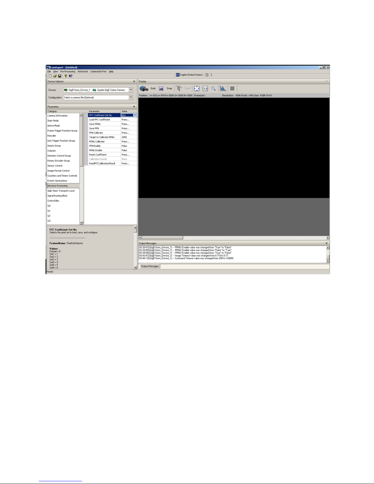
Using Sapera CamExpert with Spyder3 Cameras
CamExpert is the camera interfacing tool supported by the Sapera library. When used with a Spyder3
camera, CamExpert allows a user to test all Spyder3 operating modes. Additionally CamExpert saves the
Spyder3 user settings configuration to the camera or saves multiple configurations as individual camera
parameter files on the host system (*.ccf).
An important component of CamExpert is its live acquisition display window which allows immediate
verification of timing or control parameters without the need to run a separate acquisition program.
For context sensitive help, click on the button then click on a camera configuration parameter. A
short description of the configuration parameter will be shown in a popup. Click on the button to
open the help file for more descriptive information on CamExpert.
The central section of CamExpert provides access to the Spyder3 parameters. Note: The availability of the
parameters is dependent on the CamExpert user setting.
Teledyne DALSA 03-032-20123-00
26 Spyder3 GigE Vision SG-14 Cameras User’s Manual
CamExpert Panes
The CamExpert application uses 5 windows to simplify choosing and configuring camera files or
acquisition parameters for the installed device.
Device Selector pane: View and select from any installed Sapera acquisition device. Once a device is
selected CamExpert will only present acquisition parameters applicable to that device. Optionally
select a camera file included with the Sapera installation or saved by the user.
Parameters pane: Allows viewing or changing all acquisition parameters supported by the
acquisition device. CamExpert displays parameters only if those parameters are supported by the
installed device. This avoids confusion by eliminating parameter choices when they do not apply to
the hardware in use.
Display pane: Provides a live or single frame acquisition display. Frame buffer parameters are shown
in an information bar above the image window.
Control Buttons: The Display pane includes CamExpert control buttons. These are:
03-032-20123-00 Teledyne DALSA
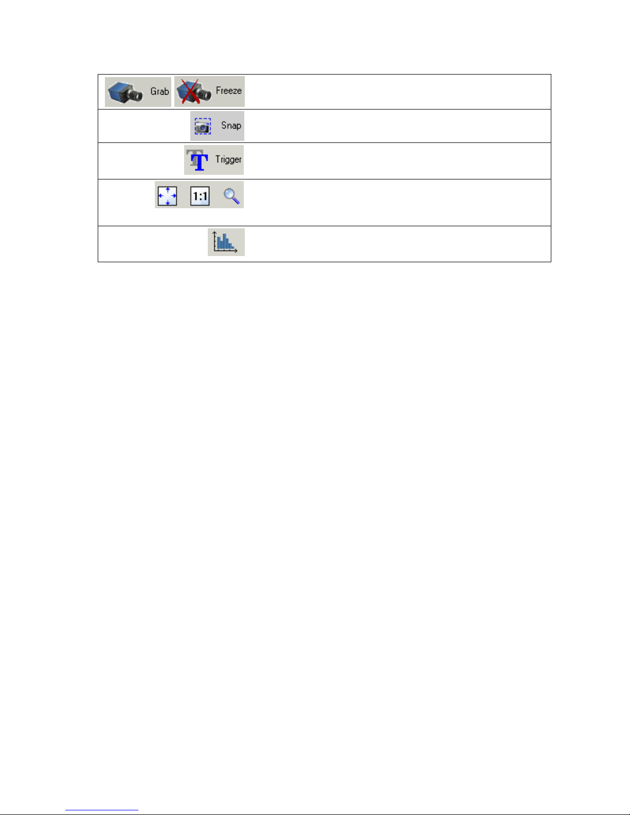
Spyder3 GigE Vision SG-14 Cameras User’s Manual 27
Acquisition control button:
Click once to start live grab, click again to stop.
Single frame grab:
Click to acquire one frame from device.
Software trigger button:
With the I/ O control parameters set to Trigger Enabled / Software
Trigger type, click to send a single software trigger command.
CamExpert display controls:
(these do not modify the frame buffer data)
Stretch image to fit, set image display to original size, or zoom the
image to any size and ratio.
Histogram / Profile tool:
Select to view a histogram or line/ column profile during live
acquisition.
Output Message pane: Displays messages from CamExpert or the device driver.
Teledyne DALSA 03-032-20123-00

28 Spyder3 GigE Vision SG-14 Cameras User’s Manual
Step 4. Camera Settings and Test Patterns
Review a Test Pattern Image
The camera is now ready to retrieve a test pattern. The Spyder3 cameras include a built-in test pattern
generator that can be used to confirm camera Ethernet connections without the need for a camera lens or
proper lighting. The test patterns are useful for verifying camera timing and connections, and to aid in
system trouble shooting.
Using CamExpert, select Image Format Control > Test Image Selector and choose one of the available
test images. Select live grab to see the pattern output. The following test patterns are available:
Figure 18. Grey horizontal step
Figure 19. Grey horizontal ramp
03-032-20123-00 Teledyne DALSA

Spyder3 GigE Vision SG-14 Cameras User’s Manual 29
At this point you are ready to start operating the camera in order to acquire images, set camera functions,
and save settings.
Camera Operation
Factory Settings
The camera ships and powers up for the first time with the following factory settings:
High sensitivity mode
Forward CCD shift direction
8 bit, 2 tap
No binning
Exposure mode: internal sync & maximum exposure time
5, 000 Hz line rate
Factory calibrated analog gain and offset
Factory calibrated FPN and PRNU coefficients
Teledyne DALSA 03-032-20123-00

30 Spyder3 GigE Vision SG-14 Cameras User’s Manual
Camera Information
Parameter
Options
Manufacturer Name
Model Name
Manufacturer Info
Camera Version
Firmware Version
Camera serial ID number
Camera Temperature
Camera Voltage
User ID
Define a camera name up to 64 characters
Read temperature
In general, the temperature read is 15 C greater than the temperature at the front
plate. The temperature should not exceed 80 °C.
Read Camera input voltage
Click to read the voltage from the camera
Read Only Parameters
Check Camera and Sensor Information
Camera and sensor information can be retrieved via a controlling application—in the examples shown here,
CamExpert. Parameters such as camera model, firmware version, sensor characteristics, etc. are read to uniquely
identify the connected device.
The camera information parameters are grouped together as members of the Camera Information set.
GigE Vision Input Controls
Verify Temperature and Voltage
To determine the voltage and temperature at the camera, use the Read Voltage and Temperature feature
found in the Camera Information set.
The temperature returned is the internal chip case temperature in degrees Celsius. For proper operation,
this value should not exceed 80 °C. If the camera exceeds the designated temperature it will shut down
an d w ill not tu rn on u ntil th e camer a’s temp erature is 73 ºC or less. Use the reset camera function.
The voltage d isp layed is t h e cam er a’s inpu t volt age. N ote that the voltage measurement feature of the
camera provides only approximate results (typically within 10%). The measurement should not be used
to set the applied voltage to the camera, but only used as a test to isolate gross problems with the supply
voltage.
03-032-20123-00 Teledyne DALSA

Spyder3 GigE Vision SG-14 Cameras User’s Manual 31
Camera Information
Parameter
Description
User Set Selector / Device Configuration
Selector
Selects the camera configuration set to load feature settings from or
save current feature settings to: factory (default) or user sets.
The Factory / Default set contains default camera feature settings.
User camera configuration sets contain feature settings previously
saved by the user.
User Set Load / Load GigE Configuration
Load the set specified by User Set Selector to the camera and make
it the active / current set.
User Set Save / Save Configuration
Save the current set as selected user set.
Saving and Restoring Camera Settings
The parameters used to select, load and save user sets are grouped together under the Camera
Information set of features.
GigE Vision Input Controls
Description of the Camera Settings
The camera operates in one of three settings:
1. Current session
2. User setting
3. Factory setting (Default, read-only)
The current settings can be saved (thereby becoming the user setting) using the User Set Save parameter.
A previously saved user setting (User Set 1) or the factory settings can be restored using the User Set
Selector and User Set Load parameters.
The relationship between these three settings is illustrated here and described below:
Figure 20. Relationship between the Camera Settings
Teledyne DALSA 03-032-20123-00

32 Spyder3 GigE Vision SG-14 Cameras User’s Manual
Current Session Active Setting
The active setting for the current session is the set of configurations that are operating while the camera is
currently running, including all unsaved changes you have made to the settings before saving them .
These active settings are stored in the camera’s volatile memory and will be lost and cannot be restored if
the camera resets or if the camera is powered down or loses power.
To save these settings for reuse the next time you power up or reset the camera, or to protect against
losing them in the case of power loss, you must save the current settings using the User Set Save
parameter. Once saved, the current settings become your User Set 1.
User Setting
The user setting is the saved set of camera configurations that you can customize, resave, and restore. By
default the user settings are shipped with the same settings as the factory set.
The command User Set Save saves the current settings to non-volatile memory as a User Set. The camera
automatically restores the last saved user settings when it resets and / or powers up.
To restore the last saved user settings, select the User Set parameter you want to restore and then select
the User Set Load parameter.
Factory (Default) Settings
The default setting is the camera settings that were shipped with the camera and which loaded during the
cam era’s first pow er -up. To load or restore the original factory settings, at any time, select the Default /
Factory Setting parameter and then select the User Set Load parameter.
Note: By default, the user settings are set to the factory settings.
Please note: the following features are not restored during a factory setting load / restore:
FFC Coefficients set number
Analog Gain selector
Blacklevel selector
Digital Offset selector
Background Subtract selector
Line selector
PRNU CalibrationTarget
Gain Calibration Target
Gain Calibration Selector
03-032-20123-00 Teledyne DALSA

Spyder3 GigE Vision SG-14 Cameras User’s Manual 33
Line Trigger
Trigger Mode
The state of the line trigger. If OFF, then the line trigger is
internally generated. If ON, then triggered by an external
signal.
Trigger Source
The external source that causes a line trigger. The line
trigger is from the GPIO_PIN0. This feature is available
only when Line Trigger Mode is set to ON.
Trigger Activation
Determines the type of signal (high or low) that will cause
a line trigger. Line Trigger Mode must be ON.
External Line Trigger Frequency
Reads the external line trigger frequency. NOTE: The
camera cannot detect frequency less than 5 Hz and will
display 1 if it cannot detect a signal. This featur e is
available when the Line Trigger Mode is set o ON and
Sensor Direction Control is set to External.
Timing: Exposure and Synchronization
Image exposures are initiated by an event. The trigger event is either the camera's programmable internal
clock used in free running mode, an external input used for synchronizing exposures to external triggers,
or a programmed function call message by the controlling computer.
Trigger commands are available as members of the Sensor Control set.
GigE Vision Input Controls
The three trigger modes are described here:
Free running (trigger disabled)
The camera free-running mode has a programmable internal timer for line rate and a programmable
exposure period. Line rate is 0.1 fps to the maximum supported by the sensor. Exposures range from the
sensor minimum to a maximum also dependent on the current line rate. This always uses Synchronous
mode where exposure is aligned to the sensor horizontal line timing.
External trigger
Exposures are controlled by an external trigger signal. External signals are isolated by an opto-coupler
input with a time programmable debounce circuit. The following section provides information on
external trigger timing.
Software trigger
An exposure trigger is sent as a control command via the network connection. Software triggers can not
be considered time accurate due to network latency and sequential command jitter. But a software trigger
is more responsive than calling a single-line acquisition (Snap command) since the latter must validate
the acquisition parameters and modify on-board buffer allocation if the buffer size has changed since the
last acquisition.
Teledyne DALSA 03-032-20123-00

34 Spyder3 GigE Vision SG-14 Cameras User’s Manual
tLine Period
twSYNC_INTtwSYNC
tPR_INT
twPR_HIGH
twPR_LOWtPR
EXSYNC
PRIN
Internal Line Valid
tTRANSFER
tREADOUT
tOVERHEAD
Ethernet Latency to PC
Memory
Valid Data From
Diagramed
ExSync
tEthernet Latency
Units
Min.
Typ.
Max.
Notes
tLine_Period
μs
27.78
1000
1K 1 Tap
14.71
1000
1K 2 Tap
54.1 1000
2K 1 Tap
27.78
1000
2K 2 Tap
54.1 1000
4k 2 Tap
twSync
ns
100
twSYNC_INT
ns
100
(3000*)
For exposure mode 4 this value needs to be
>3000ns other w ise >100ns
tPR
ns 0
twPR_LOW
ns
3000
twPR_HIGH
ns
3000
tPR_INT
ns
3000
tREADOUT
Sensor Size
# Taps
Readout Time
1024
1
25600ns
1024
2
12800ns
2048
1
51200ns
2048
2
25600ns
4096
2
tOVERHEAD
Sensor Size
# Taps
Readout Time
1024
1
725ns
1024
2
450ns
2048
1
1400ns
2048
2
725ns
Timing
Table 8: Timing Parameter Table
Table 9: tReadout Values
Table 10: tOverhead Values
03-032-20123-00 Teledyne DALSA

Spyder3 GigE Vision SG-14 Cameras User’s Manual 35
1. First set the camera mode using Exposure Mode and Line Trigger Mode commands.
2. Next, if using mode 2, 6, or 7 (see below ) use the commands Acquisition Line Rate Abs and/ or Exposure
Time Abs to set the line rate and exposure time.
Sensor Control
Exposure Mode
This feature is used to set the operation mode of the
Exposure (or shutter): Off, Timed, Trigger Width. If Off is
selected then the camera uses the maximum time according
to its line rate.
Line Trigger Group
Line Trigger Mode
The state of the line trigger. If the trigger is off, then the line
trigger is internally generated. Otherwise, the line trigger is
caused by an external signal. Modes: Off or On.
Programmable Line Rate Programmable Exposure Time
Mode
LineTriggerMode
ExposureMode
Description
A
Off (Internal)
Timed (Internal)
Yes
Yes
Internal line rate and exposure time.
Exposure mode enabled.
B
On (External)
Off (Internal)
No
No
Maximum exposure time. Exposure mode
disabled.
C
On (External)
TriggerWidth
(Internal)
No
No
Smart EXSYNC. Exposure mode enabled.
D
On (External)
Timed (Internal)
No
Yes
Fixed integration time. Exposure mode
enabled.
E
Off (Internal)
Off (Internal)
Yes
No
Internal line rate, maximum exposure
time. Exposure mode disabled.
Overhead Delay
Overhead_Delay can range from 5 to 6μs and depends on the internal operations of your computer.
Exposure Controls
The cam era can gr ab im ages in on e of sev en w ays. The cam era’s lin e rate (syn chronizat ion) can be
generated internally through the Acquisition Line Rate feature (a member of the Sensor Control set of
features) or set externally with an EXSYNC signal, depending on your mode of operation.
To select h ow you w an t the camer a’s line rat e to be generat ed:
GigE Vision Input Controls
Set the Exposure Mode
Sets th e camer a’s exp osure m od e allowin g you to control your sync, exposure time, and line rate
generation.
Note: When setting the camera to external signal modes EXSYNC must be supplied.
Teledyne DALSA 03-032-20123-00

36 Spyder3 GigE Vision SG-14 Cameras User’s Manual
Programmable Period ( command)ExposureTimeAbs
Line Period
Readout
CR Exposure Time
CR=Charge Reset
Line Period
Programmable Period
CR Exposure Time
Programmable Period ( command)AquisitionLineRateAbs
Readout
Programmable Period
Waiting Waiting
Line Period
Exposure Time
Line Period
Readout
Exposure Time
Falling Edge
Ignored During
Readout
Readout
Falling Edge
Ignored During
Readout
EXSYNC
Readout
EXSYNC
EXSYNC falling
edge ignored
during readout
Line Period
CR=Charge Reset
Readout
Line Period
EXSYNC falling
edge ignored
during readout
WaitingExposure Time
CR
Waiting
CR
Exposure Time
Exposure Modes in Detail
Mode A. Internally Programmable Line Rate and Exposure Time (Factory Setting): ExposureMode Timed and
LineTriggerMode Off (Internal)
Operates at a maximum line rate and exposure time.
When setting the line rate (using the AcquisitionLineRateAbs command), exposure time will be reduced, if
necessary, to accommodate the new line rate. The exposure time will always be set to the maximum time (line
period – line transfer time – pixel reset time) for that line rate when a new line rate requiring reduced exposure
time is entered.
When setting the exposure time (using the ExposureTimeAbs command), line time will be increased, if
necessary, to accommodate the exposure time. Under this condition, the line time will equal the exposure time
+ line transfer time.
Example 1: Exposure Time less than Line Period
Mode B. External Trigger with Maximum Exposure: ExposureMode Off and LineTriggerMode On (External)
Line rate is set by the period of the external trigger pulses. The falling edge of the external trigger marks the
beginning of the exposure.
Example 2: Line Rate is set by External Trigger Pulses.
Mode C. Smart EXSYNC, External Line Rate and Exposure Time: ExposureMode TriggerWidth and LineTriggerMode On
(External)
In this mode, EXSYNC sets both the line period and the exposure time. The rising edge of EXSYNC marks the
beginning of the exposure and the falling edge initiates readout.
Example 3: Trigger Period is Repetitive and Greater than Read Out Time.
03-032-20123-00 Teledyne DALSA

Spyder3 GigE Vision SG-14 Cameras User’s Manual 37
Sensor Control
Parameter
Description
Line Rate (Hz)
Camera line rate, in Hz. 300 Hz min., 68000 Hz max.
Only available when the camera is in Internal Mode—
trigger is disabled (Trigger Mode off).
Line rates are in the following configurations:
1k 1 tap: 300-36000 Hz
1k 2 tap: 300-68000 Hz
2k 1 tap: 300-18500 Hz
2k 2 tap: 300-36000 Hz
4k 2 tap: 300-18500 Hz
Readout
EXSYNC
Line Period
CR=Charge Reset
Readout
Line Period
Programmable period
using commandExposureTimeAbs
Programmable period
using commandExposureTimeAbs
CR CR
Exposure Time Exposure Time
Waiting
Waiting
Exposure Time
Readout
Internal Sync set with
AquisitionLineRateAbs command
Line Period
Period
Exposure Time
Readout
Line Period
EXSYNC falling
edge ignored
during readout
EXSYNC falling
edge ignored
during readout
Mode D. External Line Rate and Internally Programmable Exposure Time: ExposureMode Timed and LineTriggerMode
On (External)
Figure 21: EXSYNC controls Line Period with Internally controlled Exposure Time
Mode E. Internally Programmable Line Rate, Maximum Exposure Time: ExposureMode Off and LineTriggerMode Off
(Internal)
In this mode, the line rate is set internally with a maximum exposure time.
Figure 22: Mode 7 Camera Timing
Line Rate
To set th e cam er a’s line r ate, u se the Line Rate feature found in the Sensor Control set. This feature is
only available while the camera is operating in Internal Imaging Mode (Trigger Mode off).
GigE Vision Input Controls
Teledyne DALSA 03-032-20123-00

38 Spyder3 GigE Vision SG-14 Cameras User’s Manual
Sensor Control
Parameter
Description
Exposure Mode
This feature is used to set the operation mode of the
Exposure (or shutter): Timed , Trigger Width, Off
(maximum, according to line rate).
Exposure Time
This feature is used to set the Exposure time (in
microseconds) when Exposure Mode is set to Timed. min 3,
max 3300 us.
Frame Trigger Function Group
The Frame Trigger Control section describes all features related to frame acquisition using trigger(s).
One or many Trigger(s) can be used to control the start of an Acquisition, of a Frame. It can also be
used to control the exposure duration at the beginning of a frame.
Parameter
Description
Trigger Overlap
Specify the type of trigger overlap permitted with the
previous frame. This defines when a valid trigger will be
accepted (or latched) for a new frame
Trigger Delay Raw
Specifies the delay in microseconds (μs) to apply after the
trigger reception before activating it
The delay of the selected trigger in 1 µs increments.
Frame Trigger Source
The line that triggers a frame trigger when Frame Start
Trigger Mode is On.
Frame Trigger Software Toggle
Trigger Software is a command that can be used by an
application to generate an internal trigger when Trigger
Source is set to Softw are. To generate a trigger, choose false
first then choose true.
Active Mode
Frame Active Trigger Activation
Specifies what type of signal (i.e. high, or low) causes a
variable length frame trigger.
Frame Active Trigger Mode
Specifies whether the external variable length frame trigger
is on or off. This trigger takes precedence over the
FrameStartTrigger.
Frame Active Delay
Enable the delayer.
Exposure Time
To set th e cam er a’s exp osure tim e, use the Exposure Time feature found in the Sensor Control set. This
feature is used to set the exposure time in µs. This feature is only available when the Exposure Mode is
set to Timed. The allowable range is from 3 µs to 3300 µs.
GigE Vision Input Controls
Triggers
GigE Vision Input Controls
03-032-20123-00 Teledyne DALSA

Spyder3 GigE Vision SG-14 Cameras User’s Manual 39
Start Mode
Frame Start Trigger Mode
Specifies whether the external fixed length frame trigger is
on or off. If the FrameTriggerActiveMode is on then it takes
precedence.To turn On, please DeviceScanType to Linescan
(Start Mode).
Frame Start Trigger Activation
Specifies what type of signal(i.e. high, or low) causes a
fixed length frame trigger when Frame Start Trigger Mode
is On.
Frame Start Delay
Enable the delayer.
Line Trigger Function Group
The Line Trigger Control section describes all features related to line acquisition using trigger(s). One
or many Trigger(s) can be used to control the start of an Acquisition, of a Line. It can also be used to
control the exposure duration at the beginning of a line.
Parameter
Description
Line Trigger Mode
The state of the line trigger. If the trigger is off, then the line
trigger is internally generated otherwise it is caused by an
external signal
Line Trigger Source
The external line that causes a line trigger.The line trigger is
from GPIO_PIN0. This feature is available only when Line
Trigger Mode in set to On.
Line Trigger Activation
Specifies what type of signal(i.e. high, or low) causes a line
trigger if Line Trigger Mode is On.
External Line Trigger Frequency
Reads the external line trigger frequency. NOTE: The
camera cannot detect frequency less than 5 Hz and will
display 1 if it cannot detect a signal. This featuer is
available when the Line Trigger Mode is se to ON and
Sensor Direction Control is set to External
Read External Line Frequency
Read the external line trigger frequency and updates the
ExternalLineTriggerFrequency register. This feature is
available when the Line Trigger Mode is set to On.
Inputs Group
This group contains the features that allow the configuration of the camera physical input lines (pins)
Parameter
Description
Line Selector
This feature selects which physical line (or pin) of the external
device connector to configure. When a Line is selected, all the
other Line features will be applied to its associated I/O control
block and will condition the resulting input or output signal.
Line0-- Line Trigger, Line1-- Frame Trigger, Line2 -- Direction.
GigE Vision Input Controls
Input / Output Control
CamExpert groups the camera I / O Controls Parameters in either the Inputs group or the Outputs. These parameters
allow configuring the Spyder3 inputs and outputs for type of signal and signal polarity.
GigE Vision Input Controls
Teledyne DALSA 03-032-20123-00

40 Spyder3 GigE Vision SG-14 Cameras User’s Manual
If rotary encoder is used, Line0 -- Phase A , Line2 -- Phase B
Line Format
This feature returns or sets (if possible) the current electrical
format of the selected physical input Line: No connect, TTL,
LVDS
Line Connector Pin
Enumeration of the physical line (or pin) on the device connector.
This feature is not available when Line Format is set to Not
Connected and when Line Selector is set to a line smaller than
Line2
Line Function
Displays the line function
Line Debounce Factor
This feature control the minimum period of a input line transition
before detecting a signal transition.
Outputs Group
Parameter
Description
Output Selector
This feature selects which physical line (or pin) of the external
device connector to configure. When a Line is selected, all the
other Line features will be applied to its associated I / O control
block and will condition the resulting input or output signal.
Line0 outputs signals at PLC_Q0; Line1 outputs signals at
PLC_Q1; Line2 outputs signals at PLC_Q2; Line3 outputs signals
at PLC_Q3.
Output Format
This feature returns or sets (if possible) the current electrical format
of the selected physical output Line: No Connect, TTL, or LVDS
Analog Controls
Parameter
Description
Gain Selector
Select the channel to control the gain for
All digital channels of taps
Analog Gain (dB)
Set the gain as an amplification factor applied to the video
signal
-10 dB to +10 dB
Black Level Selector
Select which black level is controlled by the black level
parameters.
Gain, Black Level, and Background
The cameras provide gain and black level adjustments in the digital domain for the sensor. The gain and
black level controls can make small compensations to the acqu isition in situation s where lighting varies
and the lens iris cannot be easily adjusted. The user can evaluate gain and black level using CamExpert.
The parameters that control gain, black level, and background are grouped together in the Analog
Controls set.
Note th at calib r ating the gain can take u p to 10 second s. Ad just t h e GUI’s tim eou t valu es (in the
Advanced Processing set) accordingly.
A section describing camera calibration in detail is available later in this manual.
GigE Vision Input Controls
03-032-20123-00 Teledyne DALSA

Spyder3 GigE Vision SG-14 Cameras User’s Manual 41
Black Level
Control the analog black level offset as an absolute physical
value.
Digital Gain (DN)
Sets the digital system gain control.
Digital Gain (dB)
Digital gain amplification in dB for a specified tap.
Digital Offset Selector
Tap selector. Select the tap to apply the digital offset.
Digital Offset (DN)
The digital offset enables the subtraction of the artificial
A/ D offset (the analog offset) so that application of the
PRNU coefficient does not result in artifacts at low light
levels due to the offset value.
Background Subtract Selector
Tap selector. Select which tap to apply the background
subtract.
Background Subtract (DN)
Used to increase image contrast after FPN and PRNU
calibration. Subtract a background value from the digitized
image data (in DN).
1K /2K Cameras
4K Cameras
Analog Gain
-10 dB to +10 dB
Calibrated 0 dB (default)
Not available in GigE
Calibrated -10 dB (default)
Digital Gain
4096 (0 dB)(default) to 65535 (> 20 dB)
4096 (0 dB) - 12953 (+10 dB)
(default)
Image Format Control
Parameter
Description
Maximum Image Width
This feature represents the maximum width (in pixels) of
the image after horizontal binning, decimation or any other
function changing the horizontal dimensions of the image.
Default width: size of the sensor.
Image Width
Current width of the image / area of interest (in pixels).
This value is dependent on the horizontal binning and
maximum width values.
Default size width: size of the sensor.
Image Height
Actual image height in active image pixels.
Default height: 480 pixels. Maximum height: 16, 383 pixels.
Image Offset
Image start position (in pixels). The horizontal offset from
the origin to the AOI (in pixels). Default offset: 0.
Table 11: Gain Range by Camera Model
Image Size
To set the height of the image, and therefore the number of lines to scan and transmit, use the parameters
grouped under the Image Format Control set.
GigE Vision Input Controls
Teledyne DALSA 03-032-20123-00

42 Spyder3 GigE Vision SG-14 Cameras User’s Manual
Image Flip Horizontal
This feature is used to flip horizontally the image sent by
the device. Default value: not flipped.
Image Format Control
Parameter
Description
Pixel Format
Mono 8
Mono 12
Image Format Control
Parameter
Description
Sensitivity Mode
High
Low
Tall
Direction Control
Parameter
Description
Sensor Scan Direction
When in high sensitivity mode, selects the forw ard or
reverse CCD shift direction or external direction control.
This accommodates object direction change on a web and
allows you to mount the camera "upside down"
Sensor Shift External Direction
The current sensor shift direction when the direction is
Pixel Format
Use the Pixel Format feature found in the Image Format Control set to select the format of the pixel to use
during image acquisition as either Mono 8 or Mono 12 bit depth.
GigE Vision Input Controls
Sensitivity Mode
To set the sensitivity mode use the Sensitivity Mode feature found as part of the Image Format Control
set. When using high sensitivity mode, the cameras responsivity increases. High sensitivity mode permits
much greater scanning speeds in low light. It can also allow for reduced lighting levels. The available
modes are: Low, High, and Tall.
More description and examples of the sensititivy mode can be found in the Appendix.
GigE Vision Input Controls
Sensor Direction Control
Found in the I / O Control > Direction Control set of features. Note: This feature is available when in
high sensitivity mode only.
Note: the Sensor Shift features are not available when the camera is in low or tall pixel sensitivity modes.
GigE Vision Input Controls
03-032-20123-00 Teledyne DALSA

Spyder3 GigE Vision SG-14 Cameras User’s Manual 43
externally controlled. This feature is only available wne
sensorScanDirection is set to External.
Read Sensor Shift Direction
Read current direction of the external signal that controls
the sensor shift direction. This feature is available only
when sensorScanDirection is set to External.
Sensor Shift Direction
When in high sensitivity mode, you can select either forward or reverse CCD shift direction. Selectable
direction acco m mod ates object d ir ection ch ange on a w eb and allow s you to m ount the cam era ― u p side
down‖.
Figure 23: Object Movement and Camera Direction Example using an Inverting Lens
Teledyne DALSA 03-032-20123-00

44 Spyder3 GigE Vision SG-14 Cameras User’s Manual
Image Format Control
Parameter
Description
Binning Horizontal
This feature represents the number of horizontal photo-sensitive cells that
must be combined (added) together.
Update the SensorWidth, Width and OffsetX registers when changing this
value.
Camera Information
Parameter
Description
Camera Reset
Reset the camera and put it in its power-up state (either with the default
factory settings or with saved user settings).
Binning
Binning is the combining of two or more image sensor pixels to form a new combined pixel prior to
readout or digitizing. A binned image using the same exposure settings as a non -binned image will show
an improved signal-to-noise ratio, reduced scanning times (due to lower spatial resolution) and save as a
smaller image file size compared with a non-binned image, at the expense of lower image resolution.
For this camera, the default binning value is 2 x 2, 4 physical pixels on the sensor are combined into one
image pixel. This operating mode is ideal for applications that require faster acquisition and processing
times and require greater signal collection.
The Binning Horizontal feature in the Image Format Control set represents the number of horizontal
pixels that will be combined (added) together.
GigE Vision Input Controls
Resetting the Camera
The feature Camera Reset, part of the Camera Information set, resets the camera.
The camera resets with the last saved settings and the baud rate used before the reset. Previously saved
pixel coefficients are also restored.
GigE Vision Input Controls
03-032-20123-00 Teledyne DALSA

Spyder3 GigE Vision SG-14 Cameras User’s Manual 45
Analog Processing
Digital Processing
analog video
analog
gain
analog
offset
FPN
coefficients
digital
offset
PRNU
coefficients
background
subtract
digital system
gain
1k and 2k only
A B
C
D
G
FE
A. GainAbs,
CalculateCameraGain
B. BlackLevelRaw
C. CorrectionCalibrateFPN
D. DigitalOffsetRaw
E. CorrectionCalibratePRNU,
CalculatePRNUAlgorithmTargetValue
F. SubtractBackgroundRaw
G. DigitalGainRaw
Camera Calibration
Processing Chain Overview and Description
The followin g d iagram sh ow s a sim p lified block d iagr am of the camer a’s analog an d d ig ital processing
chain.
The analog processing chain begins with an analog gain adjustment, followed by an analog offset
adjustment. These adjustments are applied to the video analog signal prior to its digitization by an A/ D
converter.
The digital processing chain contains the FPN correction, the PRNU correction, the background subtract,
and the digital gain and offset.
All of these elements are user programmable and most are members of the Analog Controls and Data
Processing sets.
Figure 24: Signal Processing Chain
Teledyne DALSA 03-032-20123-00

46 Spyder3 GigE Vision SG-14 Cameras User’s Manual
Analog Processing
Optimizing offset performance and gain in the analog domain lets you achieve a better signal-to-noise
ratio and dynamic range than you would achieve by trying to optimize the offset in the digital domain
only. Therefore, you should perform all analog adjustments prior to any digital adjustments.
1. Analog gain (the Gain (dB) or Calibrate Gain Target parameters in the Analog Controls set) is
multiplied by the analog signal to increase the signal strength before the A/ D conversion. It is used
to take advantage of the full dynamic range of the A/ D converter. For example, in a low light
situation the brightest part of the image may be consistently coming in at only 50% of the DN. An
analog gain of 6 dB (2x) will ensure full use of the dynamic range of the A/ D converter. Of course
the noise is also increased.
2. The analog offset or black level (Black Level (DN) command) is an ―artificial‖ offset introd u ced into
the video path to ensure that the A/ D is functioning properly. The analog offset should be set so that
it is at least 3 times the rms noise value at the current gain.
Digital Processing
To optimize camera performance, digital signal processing should be completed after any analog
adjustments.
1. Fixed pattern noise (FPN) calibration (calculated using the Calibrate FPN parameter) is used to
subtract away individual pixel dark current.
2. The digital offset (Digital Offset (DN) parameter) en ables th e su b traction of the ―artificial‖ A / D
offset (the analog offset) so that application of the PRNU coefficient does not result in artifacts at low
light levels due to the offset value. You may want to set the Digital Offset (DN) value if you are not
using FPN correction but want to perform PRNU correction.
3. Photo-Response Non-Uniformity (PRNU) coefficients (calculated using the PRNU Target and
Calibrate PRNU, or PRNU Calibration Algorithm Selector parameters in the Data Processing
family) are used to correct the difference in responsivity of individual pixels (i.e. given the same
amount of light different pixels will charge up at different rates) and the change in light intensity
across the image either because of the light source or due to optical aberrations (e.g. there may be
more light in the center of the image). PRNU coefficients are multipliers and are defined to be of a
value greater than or equal to 1. This ensures that all pixels will saturate together.
4. Background subtract (Background Subtract (DN) parameter) and system (digital) gain (Digital
Gain (DN) parameter) are used to increase image contrast after FPN and PRNU calibration. It is
useful for systems that process 8-b it d ata bu t w an t to take ad v antage of the cam era’s 12 bit d igital
processing chain. For example, if you find that your image is consistently between 128 and 255DN (8
bit), you can subtract off 128 (Background Subtract (DN) 2048) and then multiply by 2 (Digital Gain
(DN) 8192) to get an output range from 0 to 255.
03-032-20123-00 Teledyne DALSA

Spyder3 GigE Vision SG-14 Cameras User’s Manual 47
Analog Gain and Offset Adjustment
Optimizing offset performance and gain in the analog domain allows you to achieve a better signal-tonoise ratio (dynamic range). All analog signal processing chain commands should be performed prior to
FPN and PRNU calibration and prior to digital signal processing commands.
Set Analog Gain
Analog gain is multiplied by the analog signal to increase the signal strength before the A/ D conversion.
It is used to take advantage of the full dynamic range of the A/ D converter .
The Analog Controls > Gain Selector feature selects the tap to apply the gain value to. The Gain (dB)
feature is then used to apply a gain value in a range from -10 dB to +10 dB.
Note: This feature is not available on the 4k camera model.
Calibrate Camera Gain
Instead of manually setting the analog gain to a specific value, the camera can determine appropriate gain
values. This command calculates and sets the analog gain according to the algorithm determined by the
first parameter using the Calibrate Gain Selector feature. This feature is not available for the SG-1404K80 cameras.
Teledyne DALSA 03-032-20123-00

48 Spyder3 GigE Vision SG-14 Cameras User’s Manual
Calibration algorithm to use:
Analog 8 to 13 Percent Above Target = This algorithm adjusts analog gain so that 8% to 13% of tap
region of interest (ROI) pixels are above the specified target value (i.e. Calibrate Gain Target Value).
Analog Average Pixel at Target = This algorithm adjusts analog gain so that the average pixel value in
tap ’s ROI is equal to the specified target v alu e (i.e. Calibrate Gain Target Value).
Digital Average Pixel at Target = This algorithm adjusts digital gain so that the average pixel value in
tap ’s ROI is equal to the specified target (i.e. Calibrate Gain Target Value).
Analog Peak Pixel a Target = This algorithm adjusts the analog gain so that the peak tap ROI pixels are
adjusted to the specified target (i.e. Calibrate Gain Target ).
Calibrate Gain Target. Calculation target in a range from 25% to 99% of raw DN (1024 to 4055 DN), 12 bit
LSB.
Calibration Returns:
1. Success
2. Outside of specification > Analog gain set outside ±10 dB
3. Clipped to min > Analog gain set 0, (which may be below -10 dB) or System gain set to 0.
4. Clipped to max > Analog gain set to 1023, (which may be above +10 dB) or System gain set to 65,535
(16x).
5. Timeout > FPGA did not return new end of line statistics
Notes:
This function requires constant light input while executing.
If very few tap pixels are w ithin the ROI, gain calculation may not be optimal.
When all taps are selected, taps outside of the ROI are set to the average gain of the taps that are
within the ROI.
Perform analog gain algorithms before performing FPN and PRNU calibration.
All digital settings affect the analog gain calibration. If you do not want the digital processing to have
any effect on the camera gain calibration, then turn off all digital settings by sending the commands:
DigitalOffsetRaw 0, EnablePixelCoefficients 0, SubtractBackgroundRaw 0, and DigitalGainRaw 4096
Please note: only the ―Digital A ver age Pixel at Target‖ algorithm is available on 4k models.
Also note: the Calibrate Gain Selector command can take up to 10 seconds. Please adjust the GUI's
timeout values (in the Advanced Processing set) accordingly.
03-032-20123-00 Teledyne DALSA

Spyder3 GigE Vision SG-14 Cameras User’s Manual 49
Set Analog Offset (Black Level)
Sets the analog offset. The analog offset should be set so that it is at least 3 times the rms noise value at
the current gain. The analog offset is configured for the noise at the maximum specified gain and as a
result you should not need to ad just the analog offset.
The Black Level Selector parameter selects which tap is selected: All, Tap1, or Tap2. Followed by using
the Black Level (DN) feature to select an offset value in a range from 0 to 255 DN (12 bit LSB).
Update Analog Gain Reference
The Update Gain Reference feature sets the current analog gain setting to be the 0 dB point. This is
useful after tap gain matching allowing you to change the gain on all taps by the same amount.
Calibrate the Camera to Remove Non-Uniformity
(Flat Field Correction)
Calibration Overview
When a camera images a uniformly lit field, ideally, all of the pixels will have the same gray value.
However, in practice, this is rarely the case (see example below) as a number of factors can contribute to
gray scale non-uniformity in an image: Lighting non-uniformities and lens distortion, PRNU (pixel
response non-uniformity) in the imager, FPN (fixed pattern noise) in the imager, etc.
Figure 25. Image with non-uniformities
By calibrating the camera you can eliminate the small gain difference between pixels and compensate for
light distortion. This calibration employs a two-point correction that is applied to the raw value of each
pixel so that non-uniformities are flattened out. The response of each pixel will appear to be virtually
identical to that of all the other pixels of the sensor for an equal amount of exposure.
Teledyne DALSA 03-032-20123-00

50 Spyder3 GigE Vision SG-14 Cameras User’s Manual
where
V
outpu t
=
digital output pixel value
V
input
=
digital input pixel value from the CCD
PRNU (pixel)
=
PRNU correction coefficient for this
pixel
FPN (pixel )
=
FPN correction coefficient for this pixel
Background
Subtract
=
background subtract value
System Gain
=
digital gain value
3>
Darkest Pixel (per tap)
Brightest Pixel (per tap)
Correction Overview
This camera has the ability to calculate correction coefficients in order to remove non-uniformity in the
image. This video correction operates on a pixel-by-pixel basis and implements a two point correction for
each pixel. This correction can reduce or eliminate image distortion caused by the following factors:
Fixed Pattern Noise (FPN)
Photo Response Non Uniformity (PRNU)
Lens and light source non-uniformity
Correction is implemented such that for each pixel:
V
=[(V
output
The algorithm is performed in two steps. The fixed offset (FPN) is determined first by performing a
calibration without any light. This calibration determines exactly how much offset to subtract per pixel in
order to obtain flat output when the CCD is not exposed.
The white light calibration is performed next to determine the multiplication factors required to bring
each pixel to the required value (target) for flat, white output. Video output is set slightly above the
brightest pixel (depending on offset subtracted).
– FPN (pixel ) - digital offset) * PRNU (pixel) – Background Subtract] x System Gain
input
Flat Field Correction Restrictions
It is important to do the FPN correction first. Results of the FPN correction are used in the PRNU
procedure. We recommend that you repeat the correction when a temperature change greater than 10°C
occurs or if you change the analog gain, integration time, or line rate.
PRNU correction requires a clean, white reference. The quality of this reference is important for proper
calibration. White paper is often not sufficient because the grain in the white paper will distort the
correction. White plastic or white ceramic will lead to better balancing.
Note: If your illumination or white reference does not extend the full field of view of the camera, the
camera will send a warning.
For best results, ensure that:
50 or 60 Hz ambient light flicker is sufficiently low not to affect camera performance and calibration
results.
For best results, the analog gain should be adjusted for the expected operating conditions and the
ratio of the brightest to darkest pixel in a tap should be less than 3 to 1 where:
The camera is capable of operating under a range of 8 to 1, but will clip values larger than this ratio.
03-032-20123-00 Teledyne DALSA

Spyder3 GigE Vision SG-14 Cameras User’s Manual 51
The brightest pixel should be slightly below the target output.
When 6.25% of pixels from a single row within the region of interest are clipped, flat field correction
results may be inaccurate.
Correction results are valid only for the current analog gain and offset values. If you change these
values, it is recommended that you recalculate your coefficients.
Digital Signal Processing
To optimize camera performance, digital signal processing should be completed after any analog
adjustments.
The FPN and PRNU calibration parameters are available as members of the Advanced Processing set and
are only available to Guru users.
Figure 26. Advanced Processing / Calibration Parameters
Teledyne DALSA 03-032-20123-00

52 Spyder3 GigE Vision SG-14 Cameras User’s Manual
Advanced Processing
Parameter
Description
FFC Coefficient Set No.
Selects the pixel set to load, or save. There are 4 user sets available.
Load FFC Coefficient
Loads the Flat Field Correction Coefficients (specified by the Pixel Set
Selector) from the cameras non-volatile memory.
Reset FFC Coefficients
Restores the cameras pixel coefficients to 0 for FPN and a PRNU factor of 1.
This command does not reset saved coefficients.
Save PRNU
Write all current PRNU coefficients to non-volatile memory when Pixel Set
Selector is not Default
Save FPN
Write all current FPN coefficients to non-volatile memory when Pixel Set
Selector is not Default
FPN Calibrate
Perform a Fixed Pattern Noise calibration. Please block all light from entering
the camera(i.e. cover the lens). *** WARNING: This command can take up to
3 seconds. Please adjust the GUI's timeout values
Target to Calibrate PRNU
The target value for the PRNU calibration algorithm
PRNU Calibrate
Calibrate PRNU coefficients. Ideally FPN calibration should be done before
the PRNU calibration. To calibration PRNU, the direction must not be
External. Always set proper target before click this button. *** WARNING:
This command can take up to 15 seconds.
FPN Enable
Enables and disables the fixed pattern noise correction
PRNU Enable
Enables and disables the photo response non-uniformity correction
Calibration Result
Displays the result from the flat field calibration .
Read FFC Calibration
Result
Read FFC Calibrate Result
Region of Interest X
The horizontal start of the region of interest. The region of interest is used
specify which part of the sensor to calibrate.
Region of Interest Width
The width of the region of interest. The region of interest is used specify
which part of the sensor to calibrate
GigE Vision Input Controls
03-032-20123-00 Teledyne DALSA

Spyder3 GigE Vision SG-14 Cameras User’s Manual 53
Step 1: Prepare for Calibration
For best results, the camera should be setup for calibration with similar conditions as to those in which it
will be used. For example, data mode, exposure times and line rates, scan direction, etc.
Step 2: FPN Calibration
Note that you do not need to turn off the FPN and PRNU coefficients before calibrating, the camera will
do this automatically.
1. Stop all light from entering the camera. The best way to do this is to put on lens cap.
2. Calibrate FPN using the FPN Calibrate command.
3. Use the Read FFC Calibration Result parameter to determine if your calibration was a success or
not.
4. To save the calibrated FPN coefficients to the FFC coefficient set shown, use the Set FPN Save
parameter.
Step 3: PRNU Calibration: White Calibration
Performs PRNU calibration to user entered value and eliminates the difference in responsivity between
the most and least sensitive pixel creating a uniform response to light. Using this command, you must
provide a calibration target.
Executing these algorithms causes the Background Subtract Raw value to be set to 0 (no background
subtraction) and the Digital Gain Raw value to 4096 (unity digital gain). The pixel coefficients are
disabled (Pixel Set Load 0) during the algorithm execution but returned to the state they were prior to
command execution.
1. Remove the lens cap and prepare a white, uniform target.
2. Adjust the line rate so that the average output is about 80% of the full ou tput by: adjusting the
lighting, if you are using an internal exposure mode. Or, adjust the line rate, if you are using the
Smart Exsync mode.
3. Set the PRNU target value using the Target to Calibrate PRNU command. The target value (always
counted as 12-bit) and is 1024 to 4055 DN. For example, if you want to set the target to 255 x 80% =
204 DN in 8-bit mode, then the target value is (204/ 255) x 4096 = 3277 DN in 8-bit mode. Therefore,
you can set the target to 3300 DN: Target to Calibrate PRNU is 3300.
4. Calibrate the PRNU using the PRNU Calibrate command.
5. Use the Read FFC Calibration Result parameter to determine if your calibration was a success or
not—see the belowfor the possible results.
6. To save the calibrated PRNU coefficients to the FCC coefficient set shown, use the Set PRNU Save
parameter.
7. After the above command is completed, both the FPN and PRNU coefficients are automatically
turned on.
Teledyne DALSA 03-032-20123-00

54 Spyder3 GigE Vision SG-14 Cameras User’s Manual
Digital Gain (DN) =
max output value
max output value - Background Subtract value
Digital Gain (DN) =
i
4096
PRNU Calibration Results
Success
PRNU calibration was successful.
Greater_than_1_percent_clipped
Greater than 1 % of PRNU coefficients have been calculated to be greater than the maximum allowable 8
or less than 1 (which will happen if the target is less than the maximum pixel output).
Timeout
FPGA did not return end -of-line statistics or video line.
Setting Digital Offset
The digital offset is set to zero when you perform FPN correction (Enable FPN feature). If you are unable
to perform FPN correction, you can partially remove FPN by adjusting the digital offset.
Use the Digital Offset Selector to select the taps, and the Digital Offset (DN) parameter to choose the
subtracted offset value in a range from 0 to 2048.
Subtracting Background
Use the Background Subtract features after performing flat field correction if you want to improve your
image in a low contrast scene. It is useful for systems that process 8 bit d ata but want to take advantage of
th e cam era’s 12 bit d igit al p r ocessin g chain. You shou ld try to m ak e you r d arkest p ixel in th e scene equ al
to zero.
Background Subtract Selector to select taps and Background Subtract (DN) to subtract a value in a
range from 0 to 4095 DN.
Setting Digital System Gain
Improve the signal output swing after a background subtract. When subtracting a digital value from the
digital video signal, using the Background Subtract DN feature, the output can no longer reach its
maximum.
Use this command to correct for this where:
Gain Selector: Tap selection. Digital Gain Raw: Gain setting. The gain ranges are 0 to 65535. The digital
video values are multiplied by this value where:
Use this command in conjunction with the Background Subtract Raw command.
4k model limited to 12953 (0 dB effective at factory set analog gain of -10 dB).
03-032-20123-00 Teledyne DALSA

Spyder3 GigE Vision SG-14 Cameras User’s Manual 55
Appendix A: Clear Dark Current
Setting the Readout Mode
Refer to the Clearing Dark Current section for more information on this feature.
Use the Readout Mode feature (from the Analog Controls family) to clear out dark current charge in the
vertical transfer gates immediately before the sensor is read out.
The available readout modes are Auto, Dark Current, and Immediate Readout.
Auto: Clears dark current below ~ 45% of the maximum line rate. (Default mode.)
Dark Current Clear: Dark current clear. Always clears dark. Reduces the maximum line rate.
Immediate Readout: Immediate readout. Does not clear dark current.
Notes:
The vertical transfer gates collect dark current during the line period. This collected current is added
to the pixel charge. This additional charge is especially noticeable at slower line rates.
This value is saved with the camera settings.
If the user is using internally programmable line rate and exposure time, or internally programmable
line rate and maximum exposure time, and immediate read out mode, with Acquisition LineRate
Abs at 45% of the maximum, and then Read outMode 1 is selected, the following warning will be
displayed, but the AcquisitionLineRateAbs value will not be changed: Warning 09: Internal line rate
inconsistent with readout time> The effect in both internal and external line rate modes is that an
EXSYNC is skipped and, therefore, the output will be at least twice as bright.
Gate Dark Current Clear
Image sensors accumulate dark current while they wait for a trigger signal. If the readout is not triggered
in a reasonable amount of time, then this dark current accumulation may increase to an excessive
amount. The result of this happening will be that the first row, and possibly additional rows (lines), of the
image will be corrupt.
The sensor used in the Spyder3 GEV camera contains two sources of dark current that will accumulate
with time: 1) in the photo sensitive area, an d 2) in the gates used to clock-out the charge.
The gate dark current can account for approximately 20% of the total dark current present. While the
exposure control has direct control over the amount of dark current in the photo sensitive area, it has no
control over the charge accumulated in the gates. Even with exposure control on, at low line rates, this
gate charge can cause the camera to saturate.
Using the Readout Mode command, the camera user can control the camera's behavior in order to
minimize the dark current artifact.
The modes of operation selected by the Readout Mode command are: Auto, On, or Off.
Note: This command is only available in low sensitivity and tall pixel modes. High sensitivity mode
operates only in the immediate read out position.
Teledyne DALSA 03-032-20123-00

56 Spyder3 GigE Vision SG-14 Cameras User’s Manual
0Hz
Watchdog
Frequency
Max. Line Rate in
Immediate
Readout Mode
Increasing Line Rate
Frequency
Dark Current
Clear
Immediate
Readout
Dark
Current
Clear to
Immediate
Readout
Transition
Frequency
Immediate
Readout to
Dark
Current
Clear
Transition
Frequency
Max. Line Rate in
Dark Current Clear
Mode
Mode
Transition Frequencies
Model
Dark Current Clear to Immediate
Readout Transition
Immediate Readout to Dark
Current Clear Transition
SG-14-01K40
13.6KHz
16.4KHz
SG-14-01K80
25.1KHz
30.4KHz
SG-14-02K40
7.05KHz
8.52KHz
SG-14-02K80
13.6KHz
16.4KHz
Max. Line Rate
Model
Immediate Readout Mode
Dark Current Clear Mode
SG-14-01K40
36KHz
18KHz
SG-14-01K80
68KHz
34KHz
SG-14-02K40
18.5KHz
9.25KHz
SG-14-02K80
36KHz
18KHz
Figure 27: Gate Dark Current Clear
Table 12.
Immediate read out mode (Off)
In this mode the image is read out, including accumulated dark current, immediately following the
trigger or the EXSYNC falling edge.
There are no line rate limitations other than the amount of gate d ark current that can be tolerated at low
line rates.
There are no timing or exposure anomalies other than situations where EXSYNC is removed from
camera. In this case, the camera will operate in a "watchdog" state.
For information on artifacts that may be experienced while using this mode, see the Artifacts section
below.
Gate dark current clear mode (On)
In this mode the gate dark current will be cleared continuously.
After the trigger (EXSYNC) is received, the dark current is cleared from the image sensor before the
image is acquired. The line rate is limited to ½ the maximum line rate available for that model of camera.
For information on artifacts that may be experienced while using this mode, see the Artifacts section
below.
Table 13.
03-032-20123-00 Teledyne DALSA

Spyder3 GigE Vision SG-14 Cameras User’s Manual 57
SG-14-04K40
18.5KHz
9.25KHz
Model
Exposure Delay and Max Exposure Time in Auto Mode
SG-14-01K40
27.5µs
SG-14-01K80
14.75 µs
SG-14-02K40
53.1 µs
SG-14-02K80
27.5 µs
SG-14-04K40
53.1µs
When operating in the dark current clear mode, there will be a slight delay, equivalent to one read out
time, before the actual exposure is implemented. The actual exposure time will not be altered.
Table 14.
Auto Mode (Auto)
In this mode the line rate from the camera will automatically cause a switch between the gate dark
current clear mode and non gate dark current clear mode.
The frequency of when this mode switchover occurs depends on the camera model.
In cases where the line rate is rapidly increased from below the Dark Current Clear to Immediate
Readout Transition Frequency to above the Immediate Readout to Dark Current Clear Transition
Frequency, the first line following this transition will likely be corrupted.
The table below outlines the artifacts that may be seen d uring this transition period. All subsequent lines
after this occurrence will be as expected.
In the case of a slow transition (that is, when the EXSYNC line rate increases by less than 10% of the
previous line rate) a line readout will not become corrupt.
There are also limitations on the exposure time when operating in auto mode: If the line rate exceeds half
the maximum line rate, then the exposure time cannot exceed the time stated in Table 14.
Note: DALSA recommends Auto mode for most users.
For information on artifacts that may be experienced while using this mode, see the Artifacts section
below.
Please note: The graphic below explains the relationship between the following tables and the preceding
Figure 27. The operating regions described in the tables refer to a specific region of Figure 27.
Teledyne DALSA 03-032-20123-00

58 Spyder3 GigE Vision SG-14 Cameras User’s Manual
ReadoutMode 0, Auto Mode.
Time Period
Operating Region
Refer to Figure 27.
Operating Mode
T0 Dark Current Dump state
T1 Immediate Readout state
ReadoutMode 0, Auto Mode.
Time Period
Operating Region
Refer to Figure 27.
Operating Mode
T0 Immediate Readout state
T1 Dark Current Dump state
T2 Immediate Readout state
0Hz
Watchdog
Frequency
Max. Line Rate in
Immediate
Readout Mode
Increasing Line Rate
Frequency
Dark Current
Clear
Immediate
Readout
Dark
Current
Clear to
Immediate
Readout
Transition
Frequency
Immediate
Readout to
Dark
Current
Clear
Transition
Frequency
Max. Line Rate in
Dark Current Clear
Mode
Mode
ReadoutMode 0, Auto Mode.
Dark Current Dump state
Immediate Readout state
T
0
T
1
Time Period
Operating Region
Refer to the above figure
Operating Mode
Dark Current Dump to Immediate Readout: Multi-Line Artifacts.
03-032-20123-00 Teledyne DALSA

Spyder3 GigE Vision SG-14 Cameras User’s Manual 59
ReadoutMode 2, Immediate Readout Mode.
Time Period
Operating Region
Refer to Figure 27.
Operating Mode
T0 Dark Current Dump state
T1 Immediate Readout state
ReadoutMode 0, Auto Mode.
Time Period
Operating Region
Refer to Figure 27.
Operating Mode
T0 Dark Current Dump state
T1 Immediate Readout state
ReadoutMode 0, Auto Mode.
Time Period
Operating Region
Refer to Figure 27.
Operating Mode
T0 Immediate Readout state
T1 Dark Current Dump state
EXSYNC
T
DUMP
T
INT
LVAL
Valid
F
DUMP
F
IMMEDIATE
T
VERT_TRANS
F
DUMP
LVAL
F
IMMEDIATE
Valid
EXSYNC
T
DUMP
T
INT
Dark Current Dump to Immediate Readout (T
INT
< #)
Dark Current Dump to Immediate Readout (T
INT
> #)
Dark Current Dump to Immediate Readout: Multi-Line Artifacts
Teledyne DALSA 03-032-20123-00

60 Spyder3 GigE Vision SG-14 Cameras User’s Manual
T2 Immediate Readout state
ReadoutMode 2, Immediate Readout Mode.
Time Period
Operating Region
Refer to Figure 27.
Operating Mode
T0 Dark Current Dump state
T1 Immediate Readout state
T
VERT_TRANS
LVAL
EXSYNC
T
DUMP
T
INT
F
DUMP
> DUMP (MAX)
F
EXSYNC
T
DUMP
T
INT
T
VERT_TRANS
LVAL
F
DUMP
> DUMP (MAX)
F
Dark Current Dump to Immediate Readout (T
INT
< #)
Dark Current Dump to Immediate Readout (T
INT
> #)
03-032-20123-00 Teledyne DALSA

Spyder3 GigE Vision SG-14 Cameras User’s Manual 61
ReadoutMode 0, Auto Mode.
Time Period
Operating Region
Refer to Figure 27.
Operating Mode
T0 Immediate Readout state
T1 Dark Current Dump state
ReadoutMode 0, Auto Mode.
Time Period
Operating Region
Refer to Figure 27.
Operating Mode
T0 Dark Current Dump state
T1 Immediate Readout state
T2 Dark Current Dump state
EXSYNC
T
DUMP
T
INT
T
VERT_TRANS
LVAL
Immediate Readout to Dark Current Dump: Hysteresis Artifacts
Teledyne DALSA 03-032-20123-00

62 Spyder3 GigE Vision SG-14 Cameras User’s Manual
CCD Readout Shift Register
CCD Readout Shift Register
Sensor 2(14µm x 14µm OR 10µm x 10µm)
Sensor 1 OR (14µm x 14µm 10µm x 10µm)
14/10µm
Pixel Detail
14/10µm14/10µm
Appendix B: Sensitivity Mode
Sensitivity Mode and Pixel Readout
The camera has the option to operate in either high sensitivity or low sensitivity mode or in tall pixel
mode.
When in high sensitivity mode, the camera uses both line scan sensors and its responsivity increases
accordingly. When in low sensitivity mode, the camera uses the bottom se nsor. When operating in tall
pixel mode, the camera operates using both sensors, creating a 28µm x 14µm pixel.
High sensitivity mode permits much greater scanning speeds in low light. It can also allow for reduced
lighting levels.
The sensitivity mode is software controlled through GigE-compliant interface using the Sensitivity Mode
feature, part of the Image Format Controls set.
In high sensitivity mode, the camera uses either a 14µm x 14µm pixel (1k and 2k models) or a 10µm x
10µm pixel (4k model) and captures the same image twice, resulting in a brighter image.
03-032-20123-00 Teledyne DALSA
Figure 28: High Sensitivity Mode

Spyder3 GigE Vision SG-14 Cameras User’s Manual 63
CCD Readout Shi ft Register
CCD Readout Shi ft Register
Sensor 2(14µm x 14µm OR 10µm x 10µm)
Sensor 1 (14µm x 14µm OR 10µm x 10µm )
14/10µm
Pixel DetailPixel Detail
14/10µm
CCD Readout Shi ft Register
CCD Readout Shi ft Register
Sensor 1 and 2 (28µm x 14µm OR 20µm x 10µm)
14/10µm
Pixel Detail
28/20µm
Figure 29: Low Sensitivity Mode
In low sensitivity mode, the camera uses either a 14 µm x 14 µm pixel (1k and 2k models) or a 10 µm x 10
µm pixel (4k model) and captures the image using one sensor (Sensor 1).
Figure 30: Tall Pixel Mode
In tall pixel mode, the camera uses a 28 µm x 14 µm pixel (1k and 2k) or a 20 µm x 10 µm pixel (4k model)
and captures an image two times taller than in high or low sensitivity modes, resulting in a taller image.
Teledyne DALSA 03-032-20123-00

64 Spyder3 GigE Vision SG-14 Cameras User’s Manual
Pin
Signal
Description
1
INPUT_ 0+
LVDS/ TTL format (positive)
Appendix C: GPIO Control
The cam era’s Gener al Purp ose Inpu t / Outp ut (GPIO) con n ector allow s the ca m era to receive (and in
some cases output) direct, real-time control signals that are independent from the Ethernet
communications. For example, the GPIO connector can be used to control EXSYNC, PRIN (pixel reset),
and direction signals.
You may want to use non-Ethernet control signals because Ethernet network protocols introduce a small
but measurable and unpredictable lag that may not allow for extremely precise and reliable control of
camera behavior, such as line rate, integration time, and readout direction.
In general, to configure the GPIO you need to accomplish three main tasks:
1. Assign a physical camera pin and signal to a GPIO Input number.
2. Map the GPIO Input or Output using the parameter commands located in the Line Trigger
Function, Inputs, Outputs, Direction Control, and Sensor Control groups in the GUI. (Please note
that this step has already been performed for the Beginner level scenarios described below.)
3. If you want to use applications other than those provided in the Beginner level examples, you can
use the LUT programming language to map the GPIO Input Configuration to the GPIO Output
Configuration in the Guru level.
Note: the screenshots presented in this section are from the CamExpert GUI. If you are using a different
GUI the arrangement of the commands and parameters may be different.
GPIO Getting Started: Beginner Mode
NOTE: The following instructions are based on the default settings of the camera. Cameras are shipped
from the factory in a default setting. Default settings are restored by loading the factory default (see
Trigger Settings (GURU) for details).
The GPIO Connector
The GPIO connector is used to interface external signals in and out of the camera. The connector contains
15 pins that can configure 4 inputs and 4 outputs (See Figure 1 and Table 1). Three of the four
inputs/ outputs (i.e. 0 to 2) can be configured as Off, LVDS (Low Voltage Differential Signal), or TTL
(Transistor/ Transistor Logic). The remaining input and output (i.e. 3), can be configured as either Off or
TTL.
Figure 31: GPIO Pinout
03-032-20123-00 Teledyne DALSA

Spyder3 GigE Vision SG-14 Cameras User’s Manual 65
Pin
Signal
Description
2
INPUT_0-
LVDS (negative)
3
INPUT_1+
LVDS/ TTL format (positive)
4
INPUT_1-
LVDS (negative)
5
GND
6 INPUT_2+
LVDS/ TTL format (positive)
7
INPUT_2-
LVDS (negative)
8
INPUT_3
TTL auxiliary input
9
OUTPUT_3
TTL auxiliary output
10
OUTPUT_2+
LVDS/ TTL auxiliary output
11
OUTPUT_0+
LVDS/ TTL auxiliary output
12
OUTPUT_0-
LVDS (negative)
13
OUTPUT_1+
LVDS/ TTL auxiliary output
14
OUTPUT_1-
LVDS (negative)
15
OUTPUT_2-
LVDS (negative)
Table 15: GPIO Signals
Configure GPIO Signal Levels
Before using any external triggers, the input lines must be set to a proper signal level: either TTL
(transistor-transistor logic) or LVDS (low-voltage differential signaling). The Spyder 3 GigE cameras
hardwire 3 input lines that require signal level selection:
Line0 – line trigger or rotary encoder phase A input
Line1 - Frame trigger
Line2 – Direction control or rotary encoder phase B input
Steps 1
Select the line: 0, 1, 2.
Steps 2
Select the corresponding signal format: TTL or LVDS.
Teledyne DALSA 03-032-20123-00
Figure 32: Inputs

66 Spyder3 GigE Vision SG-14 Cameras User’s Manual
This following section describes the steps required to run the camera in the available trigger modes. We
start with free running mode.
Examples: Setting the Camera Modes
Free Run Mode: Internal Line Trigger, Internal Direction Control,
Internal frame trigger
In the Line Trigger Function Group > set the parameter Line Trigger Mode value to Off,
Figure 33: Line Trigger
In the Direction Control Group > set the parameter Sensor Scan Direction > to Forward or Reverse,
depending on your application.
Figure 34: Scan Direction
03-032-20123-00 Teledyne DALSA

Spyder3 GigE Vision SG-14 Cameras User’s Manual 67
In the Rotary Encoder Group > set the value to False.
Figure 35: Rotary Encoder Group
In the Start Mode > set the Frame Start Trigger value Off.
Figure 36: Start Mode
In the Active Mode > set the Frame Active Trigger value Off.
Figure 37: Active Mode
Teledyne DALSA 03-032-20123-00

68 Spyder3 GigE Vision SG-14 Cameras User’s Manual
In the Sensor Control Group > set the desired exposure mode, exposure time and line rate.
Figure 38: Exposure Mode, Time, and Line Rate Settings
Internal Line Trigger, External Direction Control, Internal frame
trigger
Set the Frame Start Trigger and Frame Active Trigger values to off, as described above. Set the Line
Trigger Mode value to Off and the Exposure Mode, Exposure Time and Line Rate as above.
In the Direction Control Group > set the Sensor Scan Direction to External.
Set the Input Direction Signal to Line 2 (as described at the start to this section).
Figure 39: Scan Direction
03-032-20123-00 Teledyne DALSA

Spyder3 GigE Vision SG-14 Cameras User’s Manual 69
External Line Trigger, Internal Direction Control, Internal frame
trigger
In the Direction Control Group > set the parameter Sensor Scan Direction > to Forward or Reverse,
depending on your application.
Set the Frame Start Trigger and Frame Active Trigger values to off, as described above.
In the Line Trigger Function Group > Set the Line Trigger Mode value to On.
Figure 40: Line Trigger Mode
Set the Input Direction Signal to Line 0 (as described at the start to this section).
Verify the line frequency value by clicking the Read External Line Frequency parameter in the Line
Trigger Function Group, as shown in the figure above.
If the rescaler is needed, set the rescaler as shown in the following figure:
If the rescaler is enabled, the external line frequency will be modified using the Trigger Multiplier and
Trigger Divider commands, as shown above. For details, please refer to the Rescaler section in the GURU
section.
Note: the Trigger Multiplier takes the following three values only:
0 = frequency x 256
1 = frequency x 16
2 = frequency x 4096
For more information about the Rescaler, please refer to Rescaler in the GURU section.
Teledyne DALSA 03-032-20123-00
Figure 41: Rescaler

70 Spyder3 GigE Vision SG-14 Cameras User’s Manual
External Line Trigger, External Direction Control from Rotary
Encoder
Physically connect rotary Encoder phase A to pin1-5 if using TTL, or pin 1-2 if using LVDS, and phase B
to pin 6-5 if using TTL, or pin6-7 if using LVDS.
In the Line Trigger Function Group > Set the Line Trigger Mode value to On.
Set Rotary Encoder Module to True.
Figure 42: Rotary Encoder Module
Rescale the line trigger signal
The rotary encoder has its own built-in rescaler. Setting Rotary Encoder Multiply Factor to 0 produces an
output frequency that is 4 times the rotary encoder output. To set the output to be the same as rotary
encoder output, set the Rotary Encoder Multiply Factor to 1 and Rotary Encoder Drop Factor to 4.
Figure 43: Rotary Encoder Multiply Factor
03-032-20123-00 Teledyne DALSA

Spyder3 GigE Vision SG-14 Cameras User’s Manual 71
The forw ard and reverse direction is set by chan gin g ―Rotary En cod er Direct ion Phase‖.
Check the direction shown in the Direction Control Group to confirm the direction;
Figure 44: Rotary Encoder Direction Phase
In some situations, it is desirable to only respond to one direction, either forward or reverse, yEnable the
Encoder Backlash Control function and the Scan Direction to desired direction.
If the Backlash Control is disabled, the camera will respond to both directions. This may cause image
artefacts when the direction changes. To avoid this, increase the Rotary Encoder Debounce Factor, as
shown in the following figure.
Teledyne DALSA 03-032-20123-00
Figure 45: Encoder Backash Control

72 Spyder3 GigE Vision SG-14 Cameras User’s Manual
Figure 46: Rotary Encoder Debounce Factor
Figure 47: Shaft Encoder Module
External Frame Trigger: Frame Start Trigger mode
In the Frame Trigger Function Group > set the Device Scan Type to Linescan.
Figure 48: Device Scan Type
In the Active Mode group > ensure that the Frame Active Trigger Mode value is Off.
03-032-20123-00 Teledyne DALSA

Spyder3 GigE Vision SG-14 Cameras User’s Manual 73
Figure 49: Frame Trigger Mode
In the Start Mode group > set the Frame Start Trigger Mode value to ON.
Figure 50: Frame Start Trigger Mode
Note on the Frame Start Trigger
When the frame trigger goes high the software grabs a predefined number of lines , as defined in width
and height in Image Format Control.
For a software trigger toggle Frame software trigger from a False value to a True value, or from True to
False depending on the Frame Active Trigger Mode.
Enable the delayer in the Start Mode group > set the Frame Start Delay value to True.
Figure 51: Frame Start Delay
In the Frame Trigger Function Group > set the Frame Trigger Delayer value.
Teledyne DALSA 03-032-20123-00

74 Spyder3 GigE Vision SG-14 Cameras User’s Manual
Figure 52: Frame Trigger Delayer
External Frame Trigger – Frame Active Trigger mode.
In the Start Mode group > Make sure Frame Start Trigger Mode is Off.
Figure 53: Frame Start Trigger Mode: Off
In the Frame Trigger Function Group > Set the Device Scan type to Areascan.
Figure 54: Frame Trigger Source
In the Active Mode group > set the Frame Active Trigger Mode value to ON .
03-032-20123-00 Teledyne DALSA
Figure 55: Frame Trigger Mode: On

Spyder3 GigE Vision SG-14 Cameras User’s Manual 75
Note on the Frame Active Trigger
When the frame trigger goes high, the PC will collect data until either, the signal goes low, or the frame
buffer is filled. The frame height length will be determined by the length of the frame trigger.
At this point you can enable frame delayer as well.
Figure 56: Frame Active Delay
Outputs
Outputs are used to control external devices and monitor internal signals.
Step 1
Select the output line.
Step 2
Set the Signal Routing Block parameter. Refer to section ―PLC Inp u t Signal Rou tin g Block‖ for m ore
detail about PLC settings.
Important Note: Signals PLC_10 to PLC_15 should not be changed unless you are very experienced with
triggers and PLC settings.
Step 3
Set the signal output: Q0 to Q3.
Use the lookup table to output signals to one of 4 GPIO outputs.
Teledyne DALSA 03-032-20123-00

76 Spyder3 GigE Vision SG-14 Cameras User’s Manual
Figure 57: Output Selector
The signal to output can be selected from the Signal Routing Block parameters. For example, the
following figures will output line 0. Please note that the frame valid (PLC_A4) is always high since
Spyder3 is a line scan camera.
Figure 58: Signal Routing Block
Figure 59: Signal Q0 linked to the value of parameter PLC_10
03-032-20123-00 Teledyne DALSA

Spyder3 GigE Vision SG-14 Cameras User’s Manual 77
Trigger Settings: GURU Mode
In most use-cases the camera mode settings described in the Beginner section will suffice. Using the
commands and parameters available in the Guru level allow you to perform finer adjustments to the
triggers or create different use-cases from the ones predefined in the Beginner level.
The following instructions are based on the default settings of the camera. Cameras are shipped from the
factory in a default setting. Default settings are restored by loading the factory default (see the figure
below).
NOTE: loading the factory default will take 10 seconds or more to complete. If you are not using
CamExpert, it is recommended that you set your GUI timeout values to maximum setting. If you do not
adjust the GUI timeout, your GUI will disconnect during factory load.
After Factory default settings are loaded, parameters will be configured as follows;
PLC_Q7_Variable0 is set to line0, which is line trigger input:
Teledyne DALSA 03-032-20123-00

78 Spyder3 GigE Vision SG-14 Cameras User’s Manual
PLC_Q7 is fed to a rescaler input. So the rescaler will rescale line trigger signals:
PLC_Q16 is set to Line1, which is frame trigger:
PLC_Q16 is fed into delayer, so the frame trigger signal can be delayed :
PLC_Q6 is direction and is fed by line2:
03-032-20123-00 Teledyne DALSA

Spyder3 GigE Vision SG-14 Cameras User’s Manual 79
PLC_Q4_Variable0 can be PLC_I0 or PLC_I3, depending on w hether or not the rescaler is enabled:
PLC_Q12_Variable0 can be PLC_I1 or PLC_I4 depending on whether or not the delayer is enabled:
PLC_Q14_Variable0 can be PLC_I1 or PLC_I4 depending on whether or not the delayer is enabled:
Teledyne DALSA 03-032-20123-00

80 Spyder3 GigE Vision SG-14 Cameras User’s Manual
Pulse Generator
The behavior of the Pulse Generator is defined by their delay and w idth. The delay is the amount of time
the pulse is inactive prior to the pulse, and the width is the amount of time the pulse is active.
The Pulse Generator signals can be set in either triggered or periodic mode. In triggered mode, the pulse
generator is triggered by either the rising edge or high level of the input signal. When triggered, the pulse
generator is inactive for the duration of the delay, then active for the duration of the width. After that, it
will become inactive until the next trigger occurs. If a trigger occurs while pulse generator is already
handling a previous trigger, the new trigger is ignored.
In periodic mode, the trigger continuously generates a signal that is based on the co nfigured delay and
width. The period of the pulse is therefore the delay time plus the width time.
Figure 60: Pulse Generator
Pulse Generator 0 to 3
Selects which pulse generator to configure. To view the pulse generator properties, open the directory.
Width
Indicates the number of cycles (also determined by the granularity) that the pulse remains at a high level
before falling to a low level.
Delay
Indicates the number of cycles (also determined by the granularity) that the pulse remains at a low level
before rising to a high level.
Trigger Mode
Indicates how a triggered pulse generator will handle its triggers. The possible settings are:
03-032-20123-00 Teledyne DALSA

Spyder3 GigE Vision SG-14 Cameras User’s Manual 81
Trigger
Pulse_Out
pulse_delay pulse_width
Trigger
Pulse_Out
pulse_delay pulse_width
Triggered on rising edge: Indicates if a triggered pulse generator is triggered on the rising edge of an
input
Triggered on high level: Indicates is a triggered pulse generator is triggered on the high level of an
input
Triggered on falling edge: Indicates if a triggered pulse generator is triggered on the falling edge of
an input
Triggered on rising AND falling edges: Indicates if a triggered pulse generator is triggered on the
rising edge of an input and on the falling edge of an input
Triggered on low level: Indicates if a triggered pulse generator is triggered on the low level of an
input
Pulse Period (ns)
Displays the value of the parameter, in nanoseconds, of a complete delay-width cycle of the pulse
generator. This value is computed every time the delay, width or granularity is modified and is available
regardless of the periodic mode.
Pulse Frequency (Hz)
Displays the frequency of the pulse generator. This value is computed every time the delay, width or
granularity is modified and is available regardless of the periodic mode.
Pulse Generator Timing
Positive Pulse Generated from a Rising Edge Trigger
Negative Pulse Generated from a Level High Trigger
The
software can generate two internal signals using the internal pulse generators. The behavior of each of
these two pulse generators is defined by a delay and a width. As shown in the accompanying diagrams,
the delay is the time between the trigger and the pulse transitions. The width is the time the pulse stays at
the active level before transitioning. The periodic mode, the delay determines the low time of the pulse.
Each pulse generator generates a signal that can be used as an input to the GPIO Control Block. A
triggered pulse generator needs an input signal that comes from an output of the GPIO Control Block.
Note: There is one clock cycle between the output signal of a pulse generator and the outputs of the GPIO
Control Block.
The labels for the inputs from the pulse generators in the GPIO Control Block programming languages
are:
I7, for pulse generator 0
Teledyne DALSA 03-032-20123-00

82 Spyder3 GigE Vision SG-14 Cameras User’s Manual
Acceptable Line rate relative to Granularity
Gran
Precision
Minimum
Period
Maximum Period
Min.
Frequency
Max. Freq.
(ER<1%)
(30 ns)
(s)
(s)
(Hz)
(Hz)
0 1 0.00000006
0.00197
509
333,333
1 4 0.00000024
0.00786
127
83,333
2
16
0.00000096
0.03146
32
20,833
3
256
0.00001536
0.50332
2.0
1,302
I6, for pulse generator 1
Rescaler
The Rescaler lets you change the frequency of a periodic input signal. You can use the Rescaler to
multiply the period by up to 4096 or divide it by up to 4095.
Figure 61: Granularity
The Rescaler is defined by the following settings:
Granularity
The granularity is the number of clock cycles during which the rescaler checks for activity on its input.
The value to use depends on the period/ frequency of the input signal. If a frequency lies between two
different granularity settings, the lowest setting will yield a better precision. The possible values are:
The ―Min. Frequency‖ is a fixed min im um , otherw ise the incom ing signal per iod cou n ter gets
saturated (reach the maximum count).
The ―Max. Freq.‖ is a r ecommended m axim u m t o get Err or less th an 1%.
Multiplicator
The multiplier applied to the input frequency. The possible values are:
Frequency is multiplied by 256 (PLC_rsI0_Multiplier = FrequencyX256)
Frequency is multiplied by 16 (PLC_rsI0_Multiplier = FrequencyX16)
Frequency is multiplied by 4096 (PLC_rsI0_Multiplier = FrequencyX4096)
03-032-20123-00 Teledyne DALSA

Spyder3 GigE Vision SG-14 Cameras User’s Manual 83
divider
tormultiplicafrequencyxinput
frequencyoutput__
Divider
The divider applied to the input frequency. The resulting frequency is computed as follows:
Input Selection
Indicates which label in the GPIO LUT will be associated with the rescaler. Make sure you select an input
label that is not being used for its default behavior. For example, Q9 is used to send a trigger to pulse
generator 0. If pulse generator 0 is used in triggered mode, then it will be triggered by Q9 and cannot be
used as the input for the rescaler. The possible values are: Q3, Q7, Q8. Q9, Q10, Q11, Q16, and Q17.
Backup Enabled
Indicates if the rescaler will use a back-up input source if its main source stops its activity.
Backup Window
Specifies the window of time during which there can be no activity from the main input source before the
rescaler switches to the back-up source. As soon as activity is detected, the rescaler returns to its main
input source.
Backup Input
Same as the main input source
Granularity
Indicates the number of PCI clock cycles that are used for each increment of the delay and width. The
amount specified in the granularity is multiplied by 30 nanoseconds.
Other Rescaler equations are:
Granularity_setting = [1, 4, 16, 256]
Multiplier_setting = [16, 256, 4096]
Divider_setting [15:0] = [0..65535]
Granularity = 30ns x Granularity_setting
sig_in_period_counter [15:0] = MIN( INT( Signal_In_Period / Granularity ), 65535)
multiplier_out [31:0] = sig_in_period_counter[15:0] x Multiplier_setting[15:0]
divider_ou t[27:0] = INT ( multiplier_out[31:0] / Divider_setting )
Signal_Out_Period = MAX( divider_out[27:0], 2 ) x Granularity
Teledyne DALSA 03-032-20123-00

84 Spyder3 GigE Vision SG-14 Cameras User’s Manual
Counter
The counter maintains a count value that can be increased, decreased, or cleared based on input signals.
The counter outputs two signals (w hich are inputs to the GPIO LUT).
Counter Incremental Source
Specifies h ow the inp u t for in cr emen tin g th e count is h and led . Th e cou nter’s up event u ses the Q17 label
in the LUT. It can be one of the following settings:
Disabled
On the rising edge
On the falling edge
On both edges
On the high level
On the low level
Counter Decrement Event Source
Same as above but for the down event, but uses the Q16 label in the GPIO LUT.
Counter Reset Activation
Same as above but for the clear event. The clear event input of the counter does not have a predefined
label on the GPIO LUT.
Counter Reset Source
Indicates which label from the GPIO LUT that will be associated with the clear event input of the counter.
Make sure you select an input label that is not being used for its default behavior. The possible values are:
Q3, Q7, Q8, Q9, Q10, Q11, Q16, and Q17.
03-032-20123-00 Teledyne DALSA

Spyder3 GigE Vision SG-14 Cameras User’s Manual 85
Current Counter Value
Displays the current counter value
Input Debouncing
The Debouncers tab is used to configure the debouncers of the camera. The debouncers are associated
with the first and second PHYSICAL inputs of the software, usually Input 1 and Input 2.
The debouncers make sure that their corresponding inputs filter out bouncing effects. Bouncing is when
there are a few very short pulses when the input signal transitions from low to high. Without
debouncing, the controller may see these small pulses as real signals.
The debouncers make sure that the signal is truly high for the specified amount of time before it is
declared as high. The same applies to the falling edge.
Input 0 Value
Indicates the debouncing value for input 0. Each unit is equal to 16 clock cycles (30ns each), or 480ns.
Input 1 Value
Indicates the debouncing value for input 1. Each unit is equal to 16 clock cycles (30ns each), or 480ns.
Input 2 Value
Indicates the debouncing value for input 2. Each unit is equal to 16 clock cycles (30ns each), or 480ns.
Input 3 Value
Indicates the debouncing value for input 3. Each unit is equal to 16 clock cycles (30ns each), or 480ns.
Teledyne DALSA 03-032-20123-00

86 Spyder3 GigE Vision SG-14 Cameras User’s Manual
Timestamp Counter
Counter Select
Timestamp Counter (default), General Purpose Counter.
Granularity
Indicates the value of each timestamp unit of the timestamp counter. Available values are:480
nanoseconds, 1 microsecond, 100 microseconds, 10 milliseconds.
Set Mode
Indicates h ow th e tim esta m p m odu le hand les the ― set even t‖. P ossible values are:
Disabled
On Apply-The specified value is set when the user clicks the Apply button.
Rising edge input signal-W hen the signal on the ―set even t‖ inp u t rises, the t im est am p mod u le ap p lies
the specified value.
Set Input
Indicates w hich label fr om the GPIO LUT that is associated w ith the ―set even t‖ inp u t of th e timestamp
module. Make sure you select an input label that is not being used for its default behavior. The possible
values are:
0: Q3
1: Q7
2: Q8
03-032-20123-00 Teledyne DALSA

Spyder3 GigE Vision SG-14 Cameras User’s Manual 87
3: Q9
4: Q10
5: Q11
6: Q16
7: Q17
Clear Mode
Indicates h ow th e tim esta m p m odu le hand les the ―clear event‖. The p ossible values ar e:
Disabled
On Apply: The timestamp count is cleared when the user clicks the Apply button
Rising edge input signal: Then the signal on the clear event input rises, the timestamp module clears the
timestamp counter value
Clear Input
Indicates w hich label fr om the GPIO LUT that is associated w ith the ―clear event‖ inp u t of the tim est amp
module. Make sure you select an input that is not being used for its default behavior. The possible values
are:
0: Q3
1: Q7
2: Q8
3: Q9
4: Q10
5: Q11
6: Q16
7: Q17
Broadcast
When set to true, the operation is broadcasted to all other devices on the same network as the current
device.
Set Value
The valu e assigned is used w hen the ―set even t‖ of the counter occurs.
Current Value
Displays the tim estamp cou n ter’s curren t value.
Teledyne DALSA 03-032-20123-00

88 Spyder3 GigE Vision SG-14 Cameras User’s Manual
Delayer
The delayer is used to delay an input signal. The output of the delayer is the delayed version of the input
signal. A delayer is defined by:
Delay: The delay is a value expressed in the number of rising edges from the reference signal.
Reference Signal: A periodic input signal that is used to generate the delay from the input source. It is
important that this reference signal be periodic. Also note that the pulse width of the signal you want to
delay must be greater than the period of the reference signal.
Input Source Selection: The delayer does not have a pre-assigned label in the GPIO Look-Up Table (Qn).
This parameter is used to select a label that is not used by another GPIO module.
The output of the delayer is considered an input for the GPIO Look -Up Table.
The labels for the output from the delayer in the GPIO Control Block programming languages depend on
the LUT input configuration.
Figure 62: Delayer
The following sections provide details on the LUT control block, the LUT programming language and the
advanced features of the GPIO.
PLC Control
PLC control allows very precise control of the camera. Most users do not need to access the PLC functions
as the Beginner level and Guru level functions are adequate for the majority of use-cases. However,
Spyder provides a PLC and LUT programming for users who require highly specialized control of the
camera functions.
In general, to configure the PLC, you need to accomplish three main tasks:
Assign a physical camera pin and signal to a GPIO Input number.
Map the GPIO Input or Output using the parameters located in the Line Trigger Function, Inputs, Outputs, Direction
Control, and Sensor Control groups. (NOTE: This will override the factory default in beginner level. )
Use the LUT programming language to map the GPIO Input Configuration to the GPIO Output in Guru level.
The following sections provide d etails on the LUT control block, the LUT programming language and the
advanced features of the PLC.
Note: the screenshots in th is section are fr om the Cam Exp ert GUI. Other GUI’s shou ld contain a simila r
arrangement to what is shown.
03-032-20123-00 Teledyne DALSA

Spyder3 GigE Vision SG-14 Cameras User’s Manual 89
The PLC Control Block
All signals pass through the PLC Control Block. Depending on its programming, the PLC Control Block
generates output signals that can be redirected to various camera outputs.
The PLC control block uses a look up table (LUT) to generate the outputs. This LUT contains eight
different inputs, each of which can generate 18 different outputs, resulting in 256 entries of 18 bits.
Teledyne DALSA 03-032-20123-00

90 Spyder3 GigE Vision SG-14 Cameras User’s Manual
Note that all external inputs (from the camera, TTL inputs, and PLC controls) a re resynchronized. The
outputs from the look-up table are synchronous.
The LUT is programmed using a simple language. This language allows you to create logical equations
that specify the conditions that set particular outputs
Note: There is a delay of two clock cycles between the inputs of the LUT and its outputs. A clock cycle has
a period of 30 nanoseconds, so the delay is 60 nanoseconds.
The signals in the PLC Control Block are defined in the tables below.
Inputs to CamExpert are labeled In (where n is an integer from 0 to 7) and outputs are labeled Qn (where
n is an integer from 0 to 15).
03-032-20123-00 Teledyne DALSA

Spyder3 GigE Vision SG-14 Cameras User’s Manual 91
Signal
Label
Description
GPIO OUTPUT 0
Q0
GPIO output 0
GPIO OUTPUT 1
Q1
GPIO output 1
GPIO OUTPUT 2
Q2
GPIO output 2
GPIO OUTPUT 3
Q3
GPIO output 3
EXSYNC
Q4
EXSYNC
PRIN
Q5
PRIN
DIRECTION
Q6
Camera forw ard and reverse control.
CAM_CTRL (NOT
USED_
Q7
CC4 signal. Not used.
PULSE_TRIG1
Q8
Trigger for pulse generator 1. Used only when the pulse
generator is in triggered mode.
If available, can be used by one of the following modules:
Rescaler 0 input
PLC Input Signal Routing Block
The followin g code sets the first entr y in the PLC’s sign al r outing block:
Setting the Signal Routing Block is complicated by the fact that each entry in the table has a different set
of enumerated inputs. So for example, a value of 0 for i0(i.e. GPIO Input 0) means something different for
i6 (i.e. Pulse Generator 1 Output). Below is a table of enumerated values with respect to each entry.
For more information on the Signal Routing Block, refer to the section below, Signal Routing Block on
page 93.
GPIO Output Labels
Teledyne DALSA 03-032-20123-00

92 Spyder3 GigE Vision SG-14 Cameras User’s Manual
Signal
Label
Description
Delayer 0 reference signal
Counter 0 clear event input
Timestamp counter set event input
Timestamp counter clear event input
PULSE_TRIG0
Q9
Trigger for pulse generator 0. Used only when the pulse
generator is in triggered mode.
If available, can be used by one of the following modules:
Rescaler 0 input
Delayer 0 reference signal
Counter 0 clear event input
Timestamp counter set event input
Timestamp counter clear event input
PULSE_TRIG3
Q10
Trigger for pulse generator 3. Used only when the pulse
generator is in triggered mode.
If available, can be used by one of the following modules:
Rescaler 0 input
Delayer 0 reference signal
Counter 0 clear event input
Timestamp counter set event input
Timestamp counter clear event input
PULSE_TRIG2
Q11
Trigger for pulse generator 2. Used only when the pulse
generator is in triggered mode.
If available, can be used by one of the following modules:
Rescaler 0 input
Delayer 0 reference signal
Counter 0 clear event input
Timestamp counter set event input
Timestamp counter clear event input
GPIO_FVAL
Q12
Output to the internal grabber to replace or mix with the
cam era’s FVAL signal. Depen d ing on the cam era, th e FVAL
signal can be replaced or combined with the signal of this
output.
GPIO_LVAL
Q13
Output to the internal grabber to replace or mix with the
cam era’s LVAL signal. Depen d ing on the cameral, the LVAL
signal can be replaced or combined with the signal of this
output.
GPIO_TRIG
Q14
Trigger of image grabber when configured to use hard ware
trigger.
GPIO_IRQ
Q15
Trigger for an application callback. When the callback is
invoked, it provides the following information:
A bit mask of the 8 LUT inputs at the time the interrupt
was generated.
The timestamp value at the time of the interrupt.
CNT_DOWN
Q16
Trigger for the down event of counter 0.
03-032-20123-00 Teledyne DALSA

Spyder3 GigE Vision SG-14 Cameras User’s Manual 93
Signal
Label
Description
If available, can be used by one of the following modules:
Rescaler 0 input
Delayer 0 references signal
Counter 0 clear event input
Timestamp counter set event input
Timestamp counter clear event input
CNT_UP
Q17
Trigger for the up event of counter 0.
If available, can be used by one of the following modules:
Rescaler 0 input
Delayer 0 references signal
Counter 0 clear event input
Timestamp counter set event input
Timestamp counter clear event input
Signal Routing Block
In its simplest terms, the Signal Routing Block is a group of switches that let you route signals to the
Lookup Table. You can direct PLC inputs and feedback inputs to signals I0 through I7.
The Signal Routing Block lets you redirect signals from the IO Block, the Vid eo IO Block, Lookup Table,
and the Enhanced Function Block back into the Lookup Table for further processing. Because most of the
other blocks in the PLC use preconfigured inputs and outputs, the Signal Routing Block is the primary
method of routing a signal from one block to another.
Teledyne DALSA 03-032-20123-00

94 Spyder3 GigE Vision SG-14 Cameras User’s Manual
How the Signal Routing Block Works
The Signal Routing Block has 8 outputs (I0 - I7). Each output uses a 16:1 multiplexer that connects to
16 inputs.
The Signal Routing Block has more than 16 input signals, so not every input can be connected to every one of
signals I0 - I7. However, signals I0 - I7 are functionally identical, so connecting to a specific one isn’t important. If
you can’t route the input with your first choice, simply choose another.
The Lookup Table lets you connect any input signal I0-I7 to any Lookup Table output signal Q0-Q17
You can manipulate your inputs using simple or complex Boolean expressions. The following expressions are both
valid:
Q0 = I6
Q6 = !(I4 & I6) & ((I2 ^ I5) | I1)
03-032-20123-00 Teledyne DALSA

Spyder3 GigE Vision SG-14 Cameras User’s Manual 95
Correct Lookup Table Syntax
Syntax
Valid Construction
Sample Line
Line
Output = Expression EOL (end of
line)
Output
Q0, Q1, Q2, ..., Q16, Q17
Input
I0, I1, I2, ..., I6, I7
Expression
Input
Not Input
Boolean constant
Q1=I5
Q1=!I5
Q1=FALSE
Combined Expression
Expression Boolean operator
Expression
Q1=I5 & I3
Q16 = I8 | I6
Boolean Operators
& (and)
| (or)
^ (xor)
Q14 = I4 & I6
Q15 = I3 | I5
Q9 = I1 ^ I8
Not ! Q0=!I0
Q10= !(I8 & I5)
Delimiter
()
Q0 = !(I0)
Q3 = !(I1 | (I7 ^ I5))
Q6 = (I3 | I5) ^ (I1 & I2)
Boolean Constants
1, true, TRUE
0, false, FALSE
Q0 = 1
Q3 = TRUE Q6 = I3 ^ true
EOL
\ r
\ n
\ r\ n
\ n\ r
(used only for SDK, not
Coyote)
Incorrect Lookup Table Usage
Rule
Incorrect Syntax
Correct Syntax
The output must be on the left
hand side of the equation
(the value is being assigned to
Q4, not I5).
I5 = Q4
Q4 = I5
Outputs may not be on the right
hand side of the equation.
Q1 = I7 & I8
Q2 = Q1 | I5
Q1 = I7 & I8
Q2 = (I7 & I8) | I5
Equations must be separated by
a carriage return or an EOL
symbol.
Q3 = I7,Q15=I8
Q3 = I7
Q15 = I8
Teledyne DALSA 03-032-20123-00

96 Spyder3 GigE Vision SG-14 Cameras User’s Manual
How the Lookup Table Works
The Lookup Table has 8 inputs (I0 - I7) capable of two states each (true, false). Thus, the outputs have a
total number of 256 input combinations. The result of each combination can be 1 or 0.
When you modify the equations in the Lookup Table, the controller calculates the results of all 256 input
combinations and stores the result of each output as a 256-bit lookup table (hence the name). There are 18
outputs (Q0 - Q17), so the controller calculates 18 different lookup tables.
The controller then passes the resulting 18 lookup tables to the IP Engine. Knowing the value of the 8
inputs, the PLC needs only look up the value of the resulting output (for each output), rather than
calculate it. Thus, the Lookup Table can achieve a propagation delay of only one system clock cycle (30
ns), regardless of the complexity or number of Boolean expressions.
03-032-20123-00 Teledyne DALSA

Spyder3 GigE Vision SG-14 Cameras User’s Manual 97
Model SG-14-04K80
The CE Mark Evaluation of the SG-14 Camera, which is manufactured by Dalsa Inc., meets the
following requirements:
EN 55022 , EN 55011 , and FCC Part 15 Class A Emissions Requirements
EN 61326-1 and EN 55024 Immunity to Disturbances
Models SG-14-02k 40 and 80, SG-14-01k 40 and 80
The CE Mark, FCC Part 15, and Industry Canada ICES-003 Evaluation of the Spyder3 GigE Camera
meets the following requirements:
EN 55022 Class A, and EN 61326 Emissions Requirements
EN 55024, and EN 61326 Immunity to Disturbances
Name and Signature of authorized person
Hank Helmond
Quality Manager, Teledyne DALSA Inc.
Appendix D: EMC Declaration
Teledyne Dalsa's SG-14 cameras meet the requirements outlined below which satisfy the EMC
requirements for CE marking, the FCC Part 15 Class A requirements, and the Ind ustry Canada
requirements.
This equipment has been tested and found to comply with the limits for a Class A digital device,
pursuant to part 15 of the FCC Rules. These limits are designed to provide reasonable protection against
harmful interference when the equipment is operated in a commercial environment.
This equipment generates, uses, and can radiate radio frequency energy and, if not installed and used in
accordance with the instruction manual, may cause harmful interference to radio communications.
Operation of this equipment in a residential area is likely to cause harmful interference in w hich case the
user will be required to correct the interference at the user's own expense.
Changes or modifications not expressly approved by Teledyne DALSA could void the user's authority to
operate the equipment.
Teledyne DALSA 03-032-20123-00

98 Spyder3 GigE Vision SG-14 Cameras User’s Manual
Revision Number
Change Description
Revision Date
00
Beta release.
February 1 2012
Revision History
03-032-20123-00 Teledyne DALSA

Spyder3 GigE Vision SG-14 Cameras User’s Manual 99
Index
installation, 15
A
analog
processing, 46
applications, 6
exposure controls, 35
exposure mode
timing, 36
exposure modes, 35
exposure time, 38
B
C
D
E
binning, 44
black level
control, 40
calibrating the camera, 49
calibration, 49
overview, 45
camera information, 30
camera interfacing tool, 25
CamExpert, 26
certifications, 10
connectors, 20
ethernet, 21
IO, 22
location, 20
control block, 89
counter, 84
data rate, 7
debouncer, 85
delayer, 88
digital
gain, 54
processing, 46
signal processing, 51
direction
sensor shift, 43
web movement, 43
direction control, 42
electrical
specifications, 8
EMC Compliance Standards,
10
ethernet
connector, 21
ethernet card
F
factory settings, 29
features, 6
flat field correction
restrictions, 50
G
gain, 6, 47
digital, 54
Gain
control, 40
GenICam
description of, 2
website, 2
GigE Vision
description of, 2
website, 2
GPIO
and camera modes, 66
connector, 64
Control, 64
control block, 89
counter, 84
debouncer, 85
delayer, 88
Output Labels, 91
outputs, 75
PLC control, 88
pulse generator, 80
rescaler, 82
signal routing block, 93
signals, 65
timestamp counter, 86
triggers, 77
GPIO isolation, 22
GUI
CamExpert, 26
overview, 24
I
I/ O
control, 39
I/ O cable
Teledyne DALSA 03-032-20123-00

100 Spyder3 GigE Vision SG-14 Cameras User’s Manual
L
M
N
O
installation, 16
Input / Output
control, 39
input/ output, 20
interface
electrical, 8
mechanical, 8
optical, 7
IO connector, 22
LED, 21
line rate, 7
line rates, 37
lookup table, 96
mechanical, 12, 13
specifications, 8
models, 7
modes
default, 37
mounting, 13
netw ork adapter, 15
netw ork card
configuration, 17
recommendation, 17
offset, 47
optical specs, 7
outputs
TTL, 23
setting, 55
rebooting, 44
requirements
Ethernet switch, 15
network adapter, 15
requirments
system, 15
rescaler, 82
resolution, 7
responsivity, 11
revision history, 98
routers, 21
S
Sapera, 25
sensitivity mode, 62
sensitivity modes, 42
sensor block diagram, 14
settings
current, 32
factory, 29, 32
loading, 31
saving, 31
user, 32
setup
overview, 15
shift direction, 43
signal routing block, 93
size
image, 41
software
required, 7, 41
specifications
performance, 7
standards
supported, 2
switch
connection, 21
P
performance specifications, 7
pixel format, 42
pixel readout, 62
PLC control, 88
power
guidelines, 21
power connector, 20
pulse generator, 80
R
readout mod e
auto, 57
default, 56
gate dark current clear, 56
immediate, 56
03-032-20123-00 Teledyne DALSA
T
temperature
verify, 30
test pattern, 28
timestamp counter, 86
timing
mode 7, 37
Timing, 34
trigger, 38
TTL
outputs, 23
V
voltage
verify, 30
 Loading...