

Page 1
Serial Data Debug Solutions
Operator's Manual
August, 2011
Page 2

LeCroy Corporation
700 Chestnut Ridge Road
Chestnut Ridge, NY, 10977-6499
Tel: (845) 578-6020, Fax: (845) 578 5985
Internet: www.lecroy.com
© 2011 by LeCroy Corporation. All rights reserved.
Unauthorized duplication of LeCroy documentation materials other than for internal sales and distribution purposes is strictly prohibited.
However, clients are encouraged to distribute and duplicate LeCroy documentation for their own internal educational purposes.
LeCroy and other product or brand names are trademarks or requested trademarks of their respective holders. Information in this publication
supersedes all earlier versions. Specifications are subject to change without notice.
919586 RevA
Page 3

919586 RevA
iii
TABLE OF CONTENTS
Serial Data Debug Solutions Introduction .................................................................. 9
Overview ...................................................................................................................... 9
Structure of This Manual ............................................................................................. 9
Assumptions ................................................................................................................ 9
Toolsets and Supported Protocols ............................................................................... 9
Compatibility.............................................................................................................. 10
Accessing and Using Supported Protocol Toolsets .................................................... 12
Accessing and Using Supported Protocol Toolsets Overview ................................... 12
The D and TD Toolsets ............................................................................................... 12
Technical Explanation of Serial Decode and Trigger ................................................. 12
Accessing The D and TD Supported Protocol Toolsets .............................................. 13
Using The D Supported Protocol Toolsets ................................................................. 14
Decode Toolset Features and Controls...................................................................... 18
Using The T Supported Protocol Toolsets ................................................................. 22
Accessing and Using The PROTObus MAG Supported Protocol Toolset ................... 23
Operator's Manual
Decode Output Operation Detail ............................................................................... 24
Decode Measurement Parameters via Measure Setup ............................................ 24
The ProtoSync Toolset ............................................................................................... 26
The ProtoSync Toolset Overview ............................................................................... 26
The CATC Protocol View ............................................................................................ 27
The CATC Bit Tracer View - PCI Express (PCIe) Only .................................................. 30
Oscilloscope and Protocol Analyzer - A Concurrent Analysis Example ..................... 30
Accessing and Using The Graphing Tools for Supported Protocols ........................... 32
Physical Layer Eye Diagram ....................................................................................... 32
Debug Examples ........................................................................................................ 32
Using the TD Packages: Characterize Embedded Controller Performance ............... 32
Isolating and Analyzing Serial Bus Activity................................................................. 37
Serial Pattern Encoding Schemes - 8b/10b ............................................................... 45
Serial Pattern Encoding Schemes Overview .............................................................. 45
8b/10b ....................................................................................................................... 45
Using the 8b/10b Option ........................................................................................... 45
Using the 8b/10b Option Overview ........................................................................... 45
8b/10b Decode Setup Detail...................................................................................... 45
Using 8b/10b Hi-Speed Serial Triggers on Zi Oscilloscopes ....................................... 47
Encoding Table Reference ......................................................................................... 50
8b/10b Decode Search .............................................................................................. 52
General Purpose Embedded Protocols ..................................................................... 53
General Purpose Embedded Protocols Overview ..................................................... 53
Page 4

Serial Data Debug Solutions
iv
919586 RevA
I2C ............................................................................................................................... 53
SPI .............................................................................................................................. 53
UART .......................................................................................................................... 53
RS-232 ........................................................................................................................ 53
Using the I2Cbus Option ............................................................................................ 53
Using the I2Cbus Option Overview............................................................................. 53
I2C Decode Setup Detail ............................................................................................. 54
Creating an I2Cbus Trigger Condition ......................................................................... 55
I2C Trigger Setup Detail .............................................................................................. 56
Using the SPIbus Option ............................................................................................ 58
Using the SPIbus Option Overview ............................................................................ 58
SPIbus Decode Setup Detail ....................................................................................... 59
Creating a SPIbus Trigger Condition .......................................................................... 60
SPIbus Trigger Setup Detail ........................................................................................ 61
Using the UART-RS232bus Options ........................................................................... 63
Using the UART-RS232bus Options Overview ........................................................... 63
UART-RS232bus Decode Setup Detail ....................................................................... 63
Creating a UART-RS232bus Trigger Condition ........................................................... 65
UART-RS232bus Trigger Setup Detail ........................................................................ 66
Automotive and Industrial Protocols ....................................................................... 68
Automotive and Industrial Protocols Overview ........................................................ 68
CAN ............................................................................................................................ 68
LIN .............................................................................................................................. 68
FlexRay ....................................................................................................................... 68
Using the CANbus Option .......................................................................................... 68
Using the CANbus Option Overview .......................................................................... 68
CANbus Decode Setup Detail ..................................................................................... 69
Creating a CANbus Trigger Condition ........................................................................ 70
CANbus Trigger Setup Detail ...................................................................................... 70
PROTObus MAG and CANbus TDM Toolset Differences ........................................... 72
Using the LINbus Option ............................................................................................ 73
Using the LINbus Option Overview ............................................................................ 73
LINbus Decode Right-Hand Dialog ............................................................................. 73
Creating a LINbus Trigger Condition .......................................................................... 74
LINbus Trigger Setup Detail ....................................................................................... 75
Using the FlexRaybus Option ..................................................................................... 77
Using the FlexRaybus Option Overview ..................................................................... 77
FlexRaybus Decode Setup Detail ............................................................................... 78
Creating a FlexRaybus Trigger Condition ................................................................... 79
Page 5

919586 RevA
v
FlexRaybus Trigger Setup Detail ................................................................................ 80
FlexRaybus Physical Layer and Eye Diagram Analysis ............................................... 83
FlexRaybus Measurement Parameter Setup ............................................................. 85
FlexRaybus Physical Layer Measurement Parameters .............................................. 86
Viewing FlexRaybus Physical Layer Measurements .................................................. 86
Serial Audio Protocol .............................................................................................. 87
Serial Audio Protocol Overview ................................................................................. 87
I2S ............................................................................................................................... 87
Using the Audiobus Option ........................................................................................ 87
Using the AudioBus Option Overview ....................................................................... 87
AudioBus Decode Setup Detail .................................................................................. 87
Creating an AudioBus Trigger Condition ................................................................... 91
AudioBus Trigger Setup Detail ................................................................................... 92
AudioBus Measure/Graph Setup Detail .................................................................... 96
Military and Avionic Protocols ................................................................................. 97
Military and Avionic Protocols Overview .................................................................. 97
Operator's Manual
ARINC 429 .................................................................................................................. 97
MIL-STD-1553 ............................................................................................................ 97
Using the ARINC 429 Option ...................................................................................... 97
Using the ARINC 429 Option Overview ..................................................................... 97
ARINC 429 Decode Setup Detail ................................................................................ 97
ARINC 429 Decode Trace Annotations .................................................................... 100
ARINC 429 Decode Table Column Details ................................................................ 101
ARINC 429 Decode Search ....................................................................................... 102
Using the MIL-STD-1553 Option .............................................................................. 102
Using the MIL-STD-1553 Option Overview .............................................................. 102
MIL-STD-1553 Decode Setup Detail ........................................................................ 103
MIL-STD-1553 Decode Trace Annotations ............................................................... 104
MIL-STD-1553 Decode Table Column Details .......................................................... 105
MIL-STD-1553 Decode Search ................................................................................. 106
Creating a MIL-STD-1553 Trigger Condition ............................................................ 106
MIL-STD-1553 Trigger Setup Detail ......................................................................... 107
Sub-Types, Setup Format, and Right-Hand Dialogs ................................................. 108
Handset, Cellular, and Mobile Computing Protocols ................................................ 118
Handset, Cellular, and Mobile Computing Protocols Overview .............................. 118
DigRF 3G .................................................................................................................. 118
DigRF 4G .................................................................................................................. 118
D-PHY (CSI-2/DSI) ..................................................................................................... 118
M-PHY ...................................................................................................................... 118
Page 6

Serial Data Debug Solutions
vi
919586 RevA
Using the DigRF 3G Option ...................................................................................... 118
Using the DigRF 3G Option Overview ...................................................................... 118
DigRF 3G Decode Setup Detail ................................................................................. 118
DigRF 3G Decode Trace Annotations ....................................................................... 120
DigRF 3G Decode Table Column Details .................................................................. 121
DigRF 3G Decode Search .......................................................................................... 122
Using the DigRF v4 Option ....................................................................................... 122
Using the DigRF v4 Option Overview ....................................................................... 122
DigRF v4 Decode Setup Detail ................................................................................. 123
DigRF v4 Decode Trace Annotations........................................................................ 125
DigRF v4 Decode Table Column Details ................................................................... 126
DigRF v4 Decode Search .......................................................................................... 127
Customizing WordName and Comment Definitions ............................................... 128
Using the MIPI D-PHY (CSI-2/DSI) Option ................................................................ 128
Using the MIPI D-PHY Decode Option Overview ..................................................... 128
MIPI D-PHY Decode Setup Detail ............................................................................. 128
MIPI D-PHY Decode Trace Annotations ................................................................... 130
MIPI D-PHY Decode Table Column Details .............................................................. 131
MIPI D-PHY Decode Search ...................................................................................... 132
MIPI D-PHY Physical Layer Measurement Parameters ............................................ 133
Using the MIPI M-PHY.............................................................................................. 145
Using the MIPI M-PHY Decode Option Overview .................................................... 145
MIPI M-PHY Decode Setup Detail ............................................................................ 145
MIPI M-PHY Decode Trace Annotations .................................................................. 146
MIPI M-PHY Decode Table Column Details ............................................................. 147
MIPI M-PHY Decode Search ..................................................................................... 148
MIPI M-PHY Physical Layer Measurement Parameters ........................................... 148
Storage, Peripherals, and Interconnect Protocols .................................................... 154
Storage, Peripherals, and Interconnect Protocols Overview .................................. 154
SAS ........................................................................................................................... 154
Fibre Channel ........................................................................................................... 154
SATA ......................................................................................................................... 154
PCIe .......................................................................................................................... 155
USB 2.0 ..................................................................................................................... 155
USB 3.0 ..................................................................................................................... 155
Using the SAS Option ............................................................................................... 155
Using the SAS Option Overview ............................................................................... 155
SAS Decode Setup Detail ......................................................................................... 155
SAS Decode Trace Annotations................................................................................ 157
Page 7

919586 RevA
vii
SAS Decode Table Column Details ........................................................................... 157
SAS Decode Search .................................................................................................. 158
Using the FibreChannel Option ............................................................................... 159
Using the FibreChannel Option Overview ............................................................... 159
FibreChannel Decode Setup Detail .......................................................................... 160
FibreChannel Decode Trace Annotations ................................................................ 161
FibreChannel Decode Table Column Details ........................................................... 162
FibreChannel Decode Search ................................................................................... 163
Using the PCIe Option .............................................................................................. 163
Using the PCIEbus Option Overview ........................................................................ 163
PCIEbus Decode Setup Detail .................................................................................. 164
PCIEbus Decode Trace Annotations......................................................................... 167
PCIEbus Decode Table Column Details .................................................................... 168
PCIEbus Decode Search ........................................................................................... 170
PCIEbus Decode Examples ....................................................................................... 171
Using the SATA Option ............................................................................................ 175
Operator's Manual
Using the SATA Option Overview ............................................................................ 175
SATA Decode Setup Detail ....................................................................................... 176
SATA Decode Trace Annotations ............................................................................. 177
SATA Decode Table Column Details ........................................................................ 178
SATA Decode Search ................................................................................................ 178
Creating a SATA Trigger Condition .......................................................................... 179
SATA Trigger Setup Detail ........................................................................................ 180
Using the USB2 Option ............................................................................................ 183
Using the USB2 Option Overview ............................................................................ 183
USB2 Decode Setup Detail ....................................................................................... 183
USB2 Decode Trace Annotations ............................................................................. 184
USB2 Decode Table Column Details ........................................................................ 185
USB2 Decode Search ................................................................................................ 186
Creating a USB2 Trigger Condition .......................................................................... 187
USB2 Trigger Setup Detail ........................................................................................ 188
Using the USB3 Option ............................................................................................ 191
Using the USB3 Option Overview ............................................................................ 191
USB3 Decode Setup Detail ....................................................................................... 191
USB3 Decode Trace Annotations ............................................................................. 192
USB3 Decode Table Column Details ........................................................................ 193
USB3 Decode Search ................................................................................................ 194
Troubleshooting Storage, Peripherals, and Interconnects Issues ........................... 195
Polarity Correction ................................................................................................... 195
Page 8

Serial Data Debug Solutions
viii
919586 RevA
Reference .............................................................................................................. 196
Dialog Area ............................................................................................................... 196
Touch Screen Controls ............................................................................................. 196
Specifications ........................................................................................................... 199
Contact LeCroy for Support ..................................................................................... 199
Index ..................................................................................................................... 201
Page 9

Operator's Manual
919586 RevA
9
Serial Data Debug Solutions Introduction
Overview
LeCroy's Serial Data Debug Solutions (SDDS) provide different Toolsets for analysis of the Supported Protocols.
Structure of This Manual
The documentation is structured in the following manner.
Introduction - This introduction explains the Toolsets.
Accessing Toolsets - Where you'll find the various toolsets on the interface/dialogs when the different
software options are enabled.
Using Toolsets - We then take you to the point of using the general parts of a given toolset - just up to the
point where protocol specific functions come into play.
Documentation for Each Supported Protocol - These remaining sections of the manual group the various
protocols into market-specific collections.
These collections include Encoding Schemes, General Purpose Embedded Protocols, Automotive and
Industrial Protocols, Audio Protocols, Military and Avionic Protocols, Handset and Cellular Protocols,
and Storage, Peripherals, and Interconnects.
Assumptions
A basic understanding of the various serial data standard physical and protocol layer specifications, and
knowledge of how these standards are used in embedded controllers is prerequisite. In addition, a basic
understanding of oscilloscope operation (specifically the LeCroy oscilloscope with which the serial trigger and
decode option is used) is required. Wherever practical or necessary, details on specific oscilloscope features
have been included in the material.
PLEASE NOTE THE FOLLOWING:
The Dialog Area (on page 196) topic covers essential input entry methods using standard LeCroy
oscilloscope interface controls and has been included in the Reference section at the end of this
documentation for convenience.
LeCroy has a policy of frequently updating software. While screen images in this manual may not exactly
match what is seen on your oscilloscope display, be assured that the functionality is nearly identical.
We are constantly expanding the coverage of serial data standards. Some capabilities covered in this
documentation may only be available with the latest version of our firmware at www.lecroy.com.
Many of the capabilities described require updated versions of the firmware. If you are experiencing
trouble with your software option, please try updating your firmware version to 6.4.0.x or higher.
Toolsets and Supported Protocols
Serial Data Debug Solution Toolsets are integrated into the oscilloscope – no external hardware is used. Serial
data signals are input to the oscilloscope through normal passive or active probes, such as LeCroy’s ZS Series of
high impedance active probes or ZD Series of differential probes, or through the use of cable inputs.
Serial Data Debug Solution Toolsets include the following:
Decode (D) - Both D and TD Toolsets greatly increase your ability to debug and analyze embedded
controllers using serial bus communications. Protocols having only the D Toolset only have Serial Decode
functionality. The D Toolset provides algorithms that interpret and annotate protocol signals and simplify
data viewing and analysis. Trigger and Decode (TD) - Protocols having the TD Toolset have both Serial
Trigger and Decode capabilities. In addition to the Decode capabilities described above, the TD Toolset
also recognizes serial data patterns to trigger the oscilloscope at a pre-determined time; other signals
coincident with the desired serial data pattern can also be captured simultaneously.
Page 10

Serial Data Debug Solutions
10
919586 RevA
PROTObus MAG - The PROTObus MAG Toolset equips certain protocols (I
FlexRay, DigRF 3G, and MIL-STD-1553) with decoders and a variety of data extraction, timing, and other
measurement and graphing functionality. It provides insight into the serial bus standards not provided by
any other analyzer or oscilloscope. The package includes five timing measurements, three bus utilization
measurements, and two tools for extracting the encoded digital data from a serial data message and
displaying it as an analog value or waveform representation. These are essential capabilities for engineers
who require more insight into serial data protocols under test and how they interact with other circuit
elements in embedded designs. This toolset is the basic building block upon which many other LeCroy
serial trigger and decoder options can then be added and significantly extending the trigger and decode
functionality of these other packages by providing tools for more complete and faster validation and
debugging of embedded designs. It provides the deepest level of insight possible.
ProtoSync - The ProtoSync toolset provides full protocol analysis for supported protocols. While using it
you can view decoded waveforms while also viewing both CATC Protocols and Bit Tracer Data
concurrently using a Packet Analysis View. Once a linkage is established and data is transferred between
your oscilloscope and the Protocol Analysis software, the programs work simultaneously; meaning,
actions executed either on the oscilloscope or in the Protocol Analysis software updates the other in real
time for extremely comprehensive protocol analysis.
There are some toolkits specifically designed for particular protocols. Physical (P) and Graph (G) toolsets exist
and are perfectly suited for FlexRay and I2S (Audiobus) protocols, respectively.
Measure (M) - Measure is a legacy toolset used for the CANbus TDM package. Measurement applications
have been improved and made part of the PROTObus MAG toolset. Measurement toolsets provide
controls for assigning measurement parameters to your protocol signal sources.
2
C, SPI, UART, RS-232, CAN, LIN,
PLEASE NOTE THE FOLLOWING:
Currently, the PROTObus MAG toolset handles most measurement instances for supported
protocols. However, the CANbus TDM option is handled and covered in a manner differently than
PROTObus MAG. The difference are explained in PROTObus MAG and CANbus TDM Toolset
Differences (on page 72)
The TDM Toolset can also support some Graphing capabilities as well. In this context, Measure
provides various protocol-specific timing or other measurement parameters and Graph provides
the ability to extract digital data from a message and display it either as a measurement parameter
value or as an analog waveform representation of the digitally encoded data.
Physical (P) - The Physical (P, or TDP) toolset supports Physical layer analysis capable of showing an eye
diagram with a mask on FlexRaybus, MIPI D-, and M-PHY signals.
Graph (G) - The Graph (G, or TDM/G) toolset provides additional tools on protocol signal source
measurement parameters rendering graphical representations of the signal (Histo, Trend, and Track), if
desired for I2S Audiobus signals.
Compatibility
The supported protocols are packaged and indicate specific toolsets as part of the name in the following
manner:
Supported Protocol Name+bus + a Toolset Suffix
Toolset suffixes are the names (many abbreviations) listed in the previous topic (D, TD, TDM). The following
table shows a list of supported protocols and their associated toolsets.
PLEASE NOTE THE FOLLOWING:
Contact LeCroy for more information about these Software Options by referring to the Contact LeCroy for
Support (on page 199) topic for more details.
Not all supported protocol software options are offered for each oscilloscope product line.
Page 11

Operator's Manual
919586 RevA
11
Protocol
D
TD
PROTObus MAG
ProtoSync
P, G, Toolsets*
I2C • • •
SPI • • •
UART, RS-232
•
• •
CAN • • •
LIN • • •
FlexRay
•
• •
P
I2S (Audiobus)
•
•
G
ARINC 429
•
MIL-STD-1553
•
• •
DigRF 3G
•
•
DigRF v4
•
•
MIPI D-PHY/CSI-2/DSI
•
P
MIPI M-PHY
•
P
SAS • •
FibreChannel
•
•
PCIe • • •
SATA • • •
USB 2.0
•
• •
USB 3.0
•
•
Table 3-1.*Physical (P) and Graph (G) Toolsets are specialized for both FlexRay and I2S Audiobus supported protocols.
Page 12

Serial Data Debug Solutions
12
919586 RevA
Accessing and Using Supported Protocol Toolsets
Accessing and Using Supported Protocol Toolsets Overview
LeCroy's various serial data debug solutions utilize advanced trigger circuitry and advanced software algorithms
to provide powerful capability for serial data triggering, decoding, and analysis. The various software options are
accessed in the user interfaces in different ways. Some options are provided with certain oscilloscope models;
others are purchased and installed.
PLEASE NOTE THE FOLLOWING:
This section of the manual is meant to provide an initial explanation as to how the different toolsets are
accessed and used with some technical explanations at the end of the section. The information is
provided in this fashion to illustrate the commonality among toolset usage across supported protocols.
Since each serial protocol is quite different, serial trigger conditions and other settings for supported
protocols are also different. Detailed information as to how a serial trigger conditions is set up for a
specific supported protocol is covered in corresponding sections of this manual for each option. Ask your
local LeCroy representative for more information about any Serial Data Debug Solution Protocols or
Toolkits using the Contact LeCroy for Support (on page 199) topic.
The D and TD Toolsets
Technical Explanation of Serial Decode and Trigger
SERIAL DECODE
Both the D and TD options contain powerful protocol decoding and annotation software algorithms. This
algorithm is used in all LeCroy serial decoders sold with oscilloscopes, and differs slightly for serial data signals
that have a clock embedded in data or a clock separate from data.
The software algorithm examines the embedded clock (see Serial Data Debug Solutions (on page 9) for
synchronous/asynchronous protocol details) for each message based on a default (or user set) vertical level.
Once the clock signal is extracted or known, the algorithm examines the corresponding data signal at a
predetermined vertical level to determine whether a data bit is high or low. The default vertical level is usually
set to 50% and is determined from a measurement of peak amplitude of the signals acquired by the
oscilloscope. It can also be set to an (absolute) voltage level, if desired. The algorithm intelligently applies a
hysteresis to the rising and falling edge of the serial data signal to minimize the chance of perturbations or
ringing on the edge affecting the data bit decoding.
After determining individual data bit values, a different algorithm performs a decoding of the serial data
message after separation of the underlying data bits into logical groups (Header/ID, Data Length Codes, Data,
CRC, Start Bits, Stop Bits, etc.) specific to the protocol. Once the clock signal is acquired and the decoding is
completed for a serial data message with separate clock and data lines, the oscilloscope channel showing the
capture clock signal can be turned OFF to reduce screen clutter.
Finally, another algorithm provides the appropriate color coding of the message, and displays the protocol
message data on the screen, as desired, overlaid on the source trace. Various compaction schemes are utilized
to show the data during a long acquisition (many hundreds or thousands of serial data messages) or a short
acquisition (one serial data message acquisition). In the case of the longest acquisition, only the most important
information is highlighted. In the case of the shortest acquisition, all information is displayed (Header/ID, Data
Length Codes, Data, CRC, Start Bits, Stop Bits, etc.) with additional highlighting of the complete message frame.
Page 13
Operator's Manual
919586 RevA
13
Note: Although the decoding algorithm is based on a clock extraction software algorithm using a vertical level,
the results returned are the same as those from a traditional protocol analyzer using sampling point-based
decode. In addition, the clock extraction technique allows partial decoding of messages in the event of physical
layer noise, in many cases, whereas a protocol analyzer usually cannot. This is a significant advantage for the
LeCroy software algorithm.
If the sampling rate (SR) is insufficient to resolve the signal adequately based on the bit rate (BR) setup or clock
frequency, the protocol decoding is turned OFF to protect the operator from incorrect data. The minimum SR:BR
ratio required is 4:1. It is suggested that you use a slightly higher SR:BR ratio if possible, and use significantly
higher SR:BR ratios if you want to also view perturbations or other anomalies on your serial data analog signal.
SERIAL TRIGGER
TD options for some supported protocols contain advanced serial data triggering. This serial data triggering is
implemented directly within the hardware of the oscilloscope acquisition system, and contains advanced
algorithms to protocol decode, recognize, and trigger on user-defined serial data patterns. This allows a
recognized serial data pattern to be used to trigger the oscilloscope at a pre-determined time, and other signals
coincident with the desired serial data pattern can be captured simultaneously.
Accessing The D and TD Supported Protocol Toolsets
These respective toolsets are accessed by locating the Serial Decode and Serial Trigger dialogs.
Note: Users approach the Trigger and Decode software options differently. Some use Decode first, and then
Trigger. In fact, LeCroy has a Link To Trigger feature used to specifically tie Decoded channels to Triggers.
Currently, the specific protocol content in this Serial Data Debug Solutions manual covers Decode, and then
Trigger tools. Still, the content is clearly titled so no matter what order you access Trigger and Decode
software, the functionality you're looking for is never far.
DECODERS
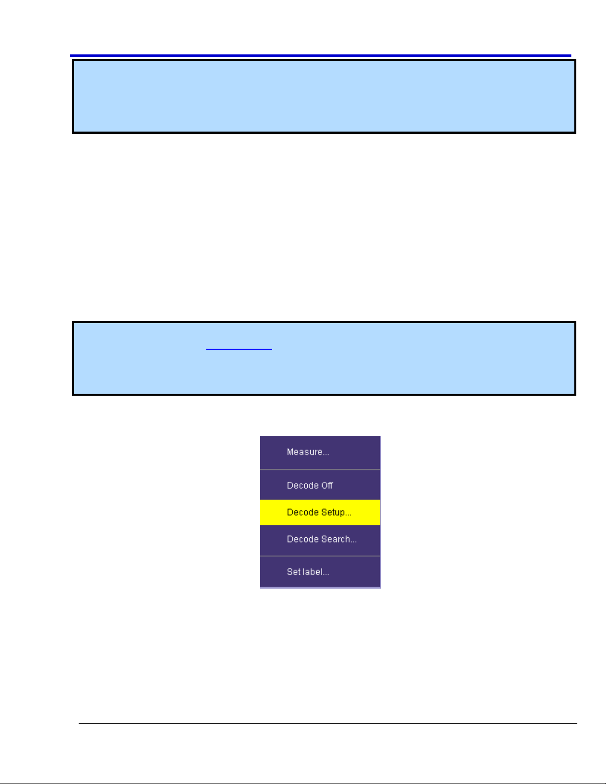
Decoders are all initially accessed by touching Analysis → Serial Decode from the menu bar.
Alternatively, you can also touch a Channel or Memory trace descriptor label showing its corresponding (channel
or memory) dialog, and then touch the Decode button listed shown on the lower part of the dialog. If a decode
table is already displayed, you can shortcut to the decode setup by touching the color-coded protocol name in
the upper-left corner of the decode table itself. See Protocol Results Table (on page 19) for more information.
Page 14
Serial Data Debug Solutions
14
919586 RevA
Some oscilloscope models also allow you to access the Serial Decode dialog the following ways:
Touch the grid display of a Channel, Memory, or Math trace and a pop-up dialog shows a Decode Setup...
shortcut if available on your instrument model. Touch this shortcut.
Press the Decode front panel button if available on your instrument model. The Serial Decode dialog is
then shown on the screen.
Use any of the aforementioned methods to access the main Serial Decode... dialog is shown.
TRIGGERS
Triggers are accessed by touching Trigger → Trigger Setup... from the menu bar. Alternatively, you can also
touch the Trigger trace descriptor label.
Note: Some oscilloscope models may also have a Trigger front panel button which shows the main Serial
Decode dialog when pressed.
Use your preferred method to access the main Trigger dialog.
Using The D Supported Protocol Toolsets
The main Serial Decode dialog acts as a summary page for your decode settings.
MAIN SERIAL DECODE DIALOG
There are four independent decoders. A user can operate up to four at a single time, although limitations may
occur with regard to how the numbers of channels are accommodated at one time. Practically speaking, if a user
decodes signals with a clock and data line (and perhaps also a chip select or other third line), then two
simultaneous decodes is the maximum number using the LeCroy oscilloscope analog channels. The addition of
the MS-250 or MS-500 Mixed Signal Oscilloscope options allow usage of digital lines for trigger and decoding,
which preserves analog channels for other uses. Contact your local LeCroy sales office for more information
about this option.
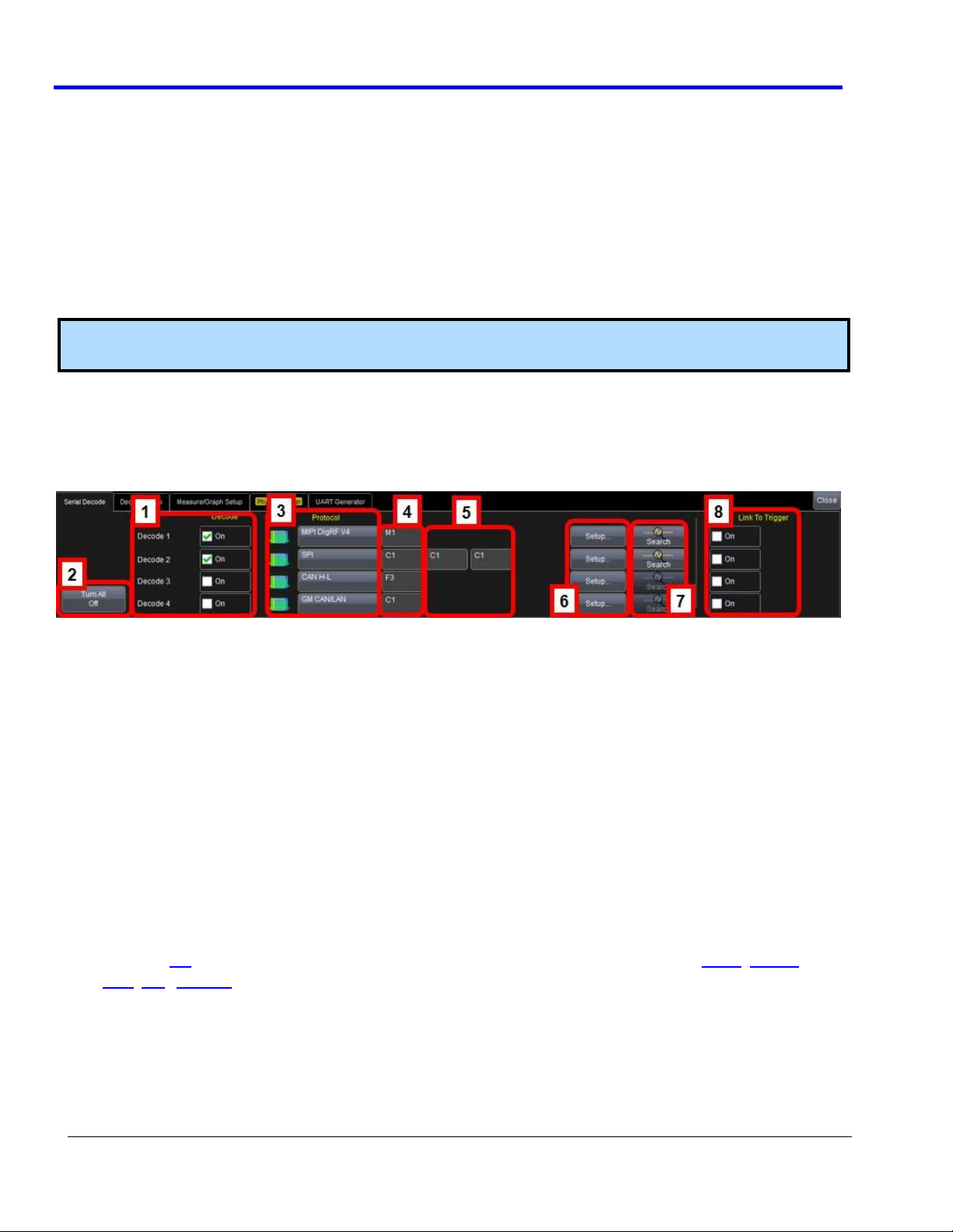
Numbered labels on this screen-shot correspond with the following explanations.
1. Decode - Mark or un-mark this checkbox to quickly enable or disable decoded signals.
2. Turn All Off - This button is provided for a convenient way to instantly disable all the decoded signals.
3. Protocol - Touch this field and select a desired protocol from the ones you have installed on your
instrument.
4. Source - Select which signal source to which you wish to apply your selected protocol.
5. Data and Clock Selection - These controls are available for certain protocols and provide pop-up channel
or source selections for the corresponding decode. Some protocols may require a third selection (for
instance, SPI also requires a Chip or Slave Selection). Asynchronous protocols, such as UART, RS-232,
CAN, LIN, FlexRay, and most high-speed serial data signals only require a single source.
6. Setup - Use this button to quickly access the corresponding detailed Decode Setup dialog for the
particular protocol selected.
7. Search - Use this button to quickly create a Zoom of the corresponding decoded signal. The right-hand
dialog of this Zoom provides search capabilities for the decode signal.
8. Link To Trigger - Mark or un-mark this checkbox to quickly tie the decoded signal to an additional Trigger
setup. This provides a faster, easier setup where the trigger is set similar as the decoder.
Page 15
Operator's Manual
919586 RevA
15
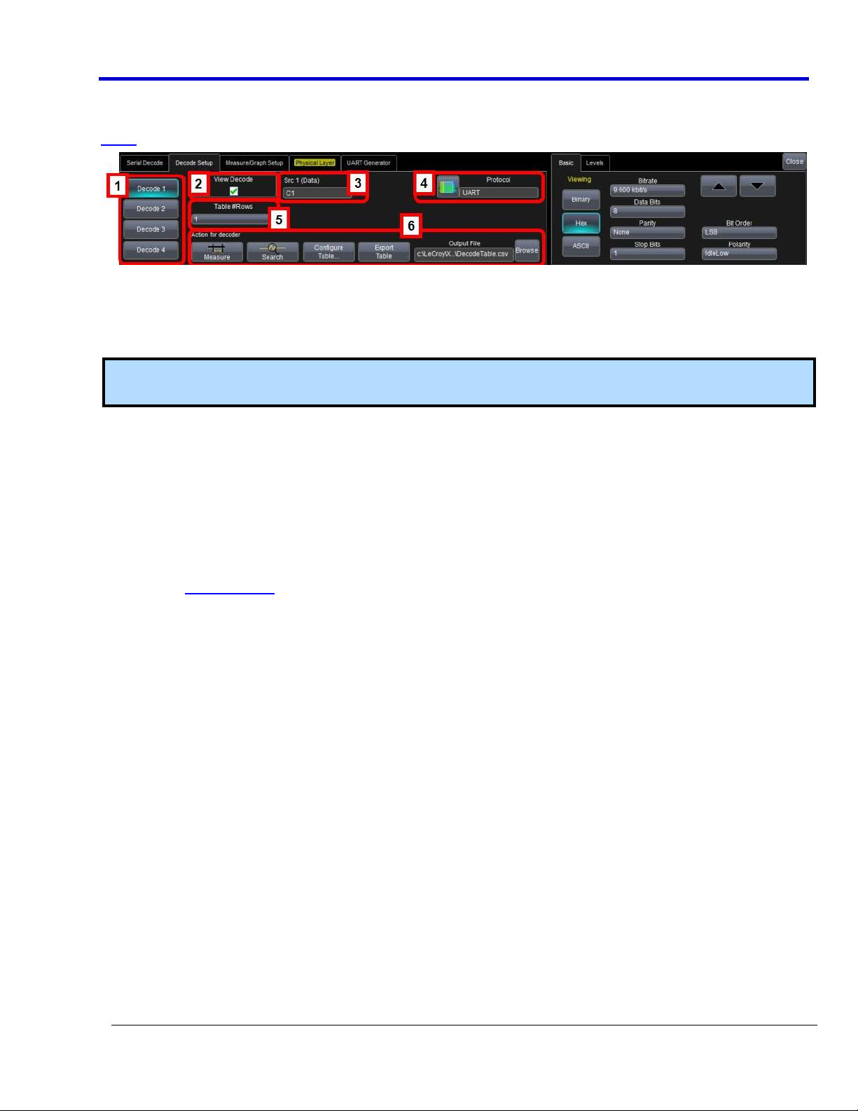
THE DECODE SETUP DIALOG
The Decode Setup dialog is where the details of a specific protocol decode is entered. It appears as follows (the
UART Decode Setup dialog is shown as an example):
This is a single tab with an indicator on the left side describing to which of the four decoders the setup
information pertains.
The left side of this dialog box is described here (the right side is explained in the protocol specific topics).
Numbered callouts correspond with the following explanations.
Note: DigRF 3 and 4G protocols are the only exceptions where a View I & Q button is available in place of
Measure in the Action for decoder section of the main Decode Setup dialog.
1. Decoder # Buttons - Indicates which of the four decoders to which the current information pertains.
2. View Decode Checkbox - Use this checkbox to turn decoding turned ON or OFF for the particular decoder.
Decoding ON provides a highlight of each message frame with color-coded highlighting and decoding of
the various protocol message portions.
PLEASE NOTE THE FOLLOWING:
If the View Decode checkbox is checked, the Table display is also shown. When the View Decode
checkbox is not marked the Table display is not shown.
When the Table is displayed, it appears similar to that shown previous (the example shown is for
MIL-STD-1553).
The first column heading (top left most cell of the table) bears the name of the corresponding
protocol. The cell's fill color matches the protocol color used on the grid display. Touching this
colorized, first column heading opens the Decode Setup dialog.
Touching the number cell (first cell) for each table row automatically sets up a Zoom for the
corresponding message position.
Page 16
Serial Data Debug Solutions
16
919586 RevA
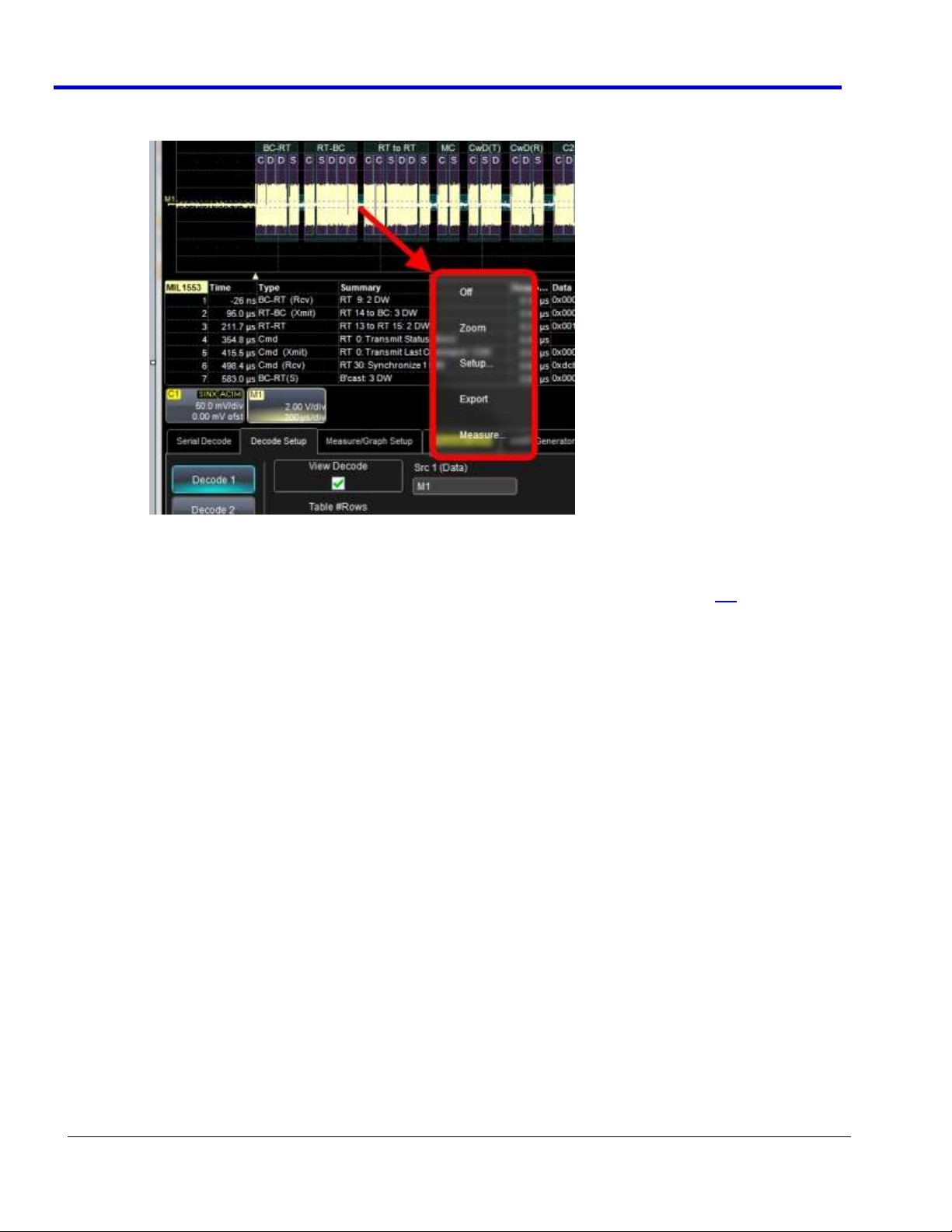
Touching anywhere else on the table shows a pop-up with Off, Zoom, Setup..., Export, and
Measure... choices.
Decoding of an entire acquisition with very long acquisitions including thousands of messages
takes longer than shorter acquisitions.
3. Source Selection - Touch these selections to open a pop-up dialog where you can select sources for Data,
and (for some protocols) controls for Clock and other lines - for example Chip Select for SPI.
PLEASE NOTE THE FOLLOWING:
Source selection is dynamically linked to the Protocol selection, so the appearance and number of
sources to choose changes based on your selected Protocol.
Source can be a Channel (C1 – C4), a Memory Trace (M1 – M4), a Math Function (F1 – F4), or
digital lines (D1 - D36 on MS-250 or MS-500).
Use a Channel for a new, real-time acquisition.
Use a Memory for recalling saved data from a previous acquisition for further analysis. Refer to
your oscilloscope’s Save and Recall Waveforms topic for more details.
Use a Math Function to view decoded data on Sequence mode acquisitions. Sequence Mode is a
unique capability where you can utilize oscilloscope memory to capture events widely spaced in
time and then view them sequentially. Reference the chapter on Isolating and Analyzing Serial Bus
Activity for more information on setting the oscilloscope up in this mode.
4. Protocol Selection - Touch this selection to open a pop-up dialog box and choose a protocol decoder.
Depending on the decoder selected, the correct inputs (Clock, Data, and a third line, if required) are
shown to the left.
Page 17
Operator's Manual
919586 RevA
17
5. Table #Rows - Touch this option and provide a value (1-20) for the number of table rows for display. One
row of data is shown by default. If a value of 1 - 4 rows is provided, the scroll bar to the right of the table
is replaced with a pop-up scroll for more convenient use.
6. Action for Decoder Toolbar - Various buttons on this toolbar provide context-sensitive shortcuts for
decoding.
Search allows quick creation of a zoom trace and changes the dialog box to the zoom/search dialog
box.
Acquire long records of message data, and use Search to look through the record for a specific
message. When the message meeting the search criteria is found, the complete message is then
shown with the Zoom Trace. Use the arrow buttons to navigate forward and backward through the
messages. Unsuccessful searches are noted with a line of text.
Configure Table displays a pop-up dialog box specific to a particular protocol. The dialog contains
checkboxes for various columns in the table. Check or uncheck the checkboxes to show or hide
specific columns on the table.
Export Table exports the complete protocol table data to a .CSV file.
The Output File name and directory can be selected by the user using the controls to the right.
Click the Browse button to select a file.
Note: If you have the PROTObus MAG toolkit option, those screens are easily accessed from the Decode Setup
screen by clicking either the Measure button or the Measure/Graph Setup... tab.
Page 18
Serial Data Debug Solutions
18
919586 RevA
Decode Toolset Features and Controls
DECODE TOOLSET FEATURES AND CONTROLS OVERVIEW
Data packets (or messages) on properly decoded signals for a given protocol can be easily viewed using Serial
Decode Trace Annotations (below), the Protocol Results Table (on page 19), and/or by Searching for Messages
(on page 21) (Types and Subtypes). These concurrent tools provide fast insight and perspective and are very
effective when used together.
PLEASE NOTE THE FOLLOWING:
Messages for most protocols are classified into Frames, Errors, Unknown or Grouped Primitives specific to
a given protocol. Sub Types then further classify each main message type into more protocol-specific
messages.
Protocol-specific topics may define a few messages while explaining how to access annotations, table
results, and search. Please refer to the corresponding protocol specification (maintained by groups
external to LeCroy). Links to these groups can be found in corresponding Overview content for each
market-specific collection.
LeCroy's market-specific collections of protocol solutions include Encoding Schemes, General Purpose
Embedded Protocols, Automotive and Industrial Protocols, Audio Protocols, Military and Avionic
Protocols, Handset and Cellular Protocols, and Storage, Peripherals, and Interconnects.
Specifications are subject to change without notice.
SERIAL DECODE TRACE ANNOTATIONS
When protocol signals are decoded and shown on the grid display area, highlighted overlays are shown to help
label specific data within the signal.
Information Shown Based on Annotation Rectangle Width
The information shown on a given annotation is affected by the rectangle width.
Annotations may include name, repetitions, and the contents of the details table display column, provided the
rectangle is wide enough. Sizes and information displayed are based on the following:
If an annotation rectangle is less than 10 pixels wide no annotation is shown.
Only the short form name is shown for annotation rectangles > 10 but < 100 pixels wide.
The long form name and repetition count are shown on annotation rectangles > 100 but < 500 pixels
wide.
Details are also shown on rectangles > 500 pixels.
Page 19
Operator's Manual
919586 RevA
19
PROTOCOL RESULTS TABLE
The protocol results table provides a quick and easy way to understand all of your protocol data as decoded by
the oscilloscope, even when messages are too compact to allow annotation on the display. In addition, the table
provides a quick and easy method to view decode results and quickly zoom to a specific message. Since the table
uses the decoded data (extracted as previously described) as its source, the View Table button (from the user
interfaces) is always checked and the table is shown by default as signals are decoded.
Note: All protocols with Decode (D) capability have a corresponding decode result table. Selecting a row on
the table creates a zoom of the specific row/message, regardless of protocol. Refer to Using The D Supported
Protocol Toolsets (on page 14) for more information about the View Table button and other information
about the protocol results table.
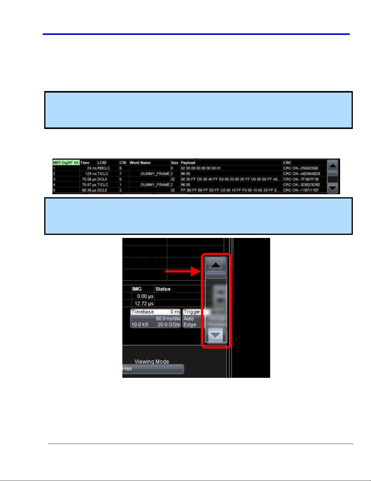
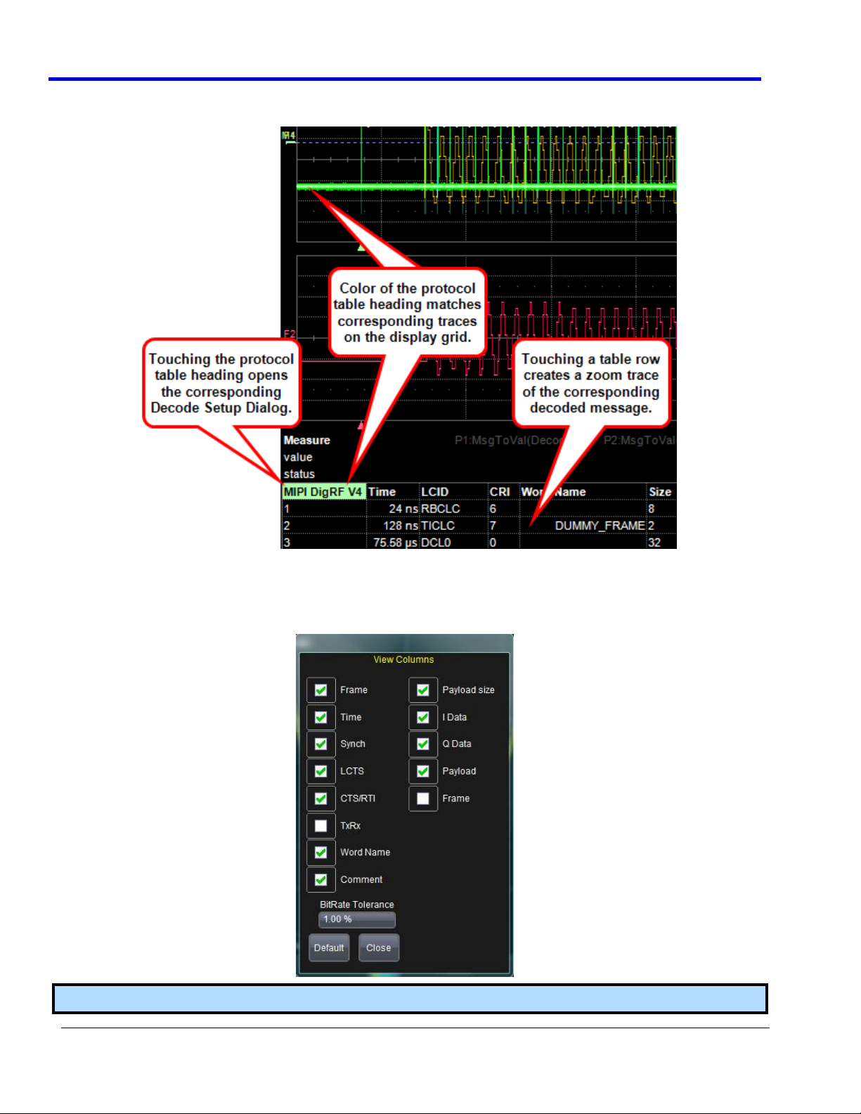
When displayed, the protocol results table appears under the waveform grid. The following protocol results
table is showing DigRF V4 data (each protocol's table looks different) and provides an example of what the table
looks like:
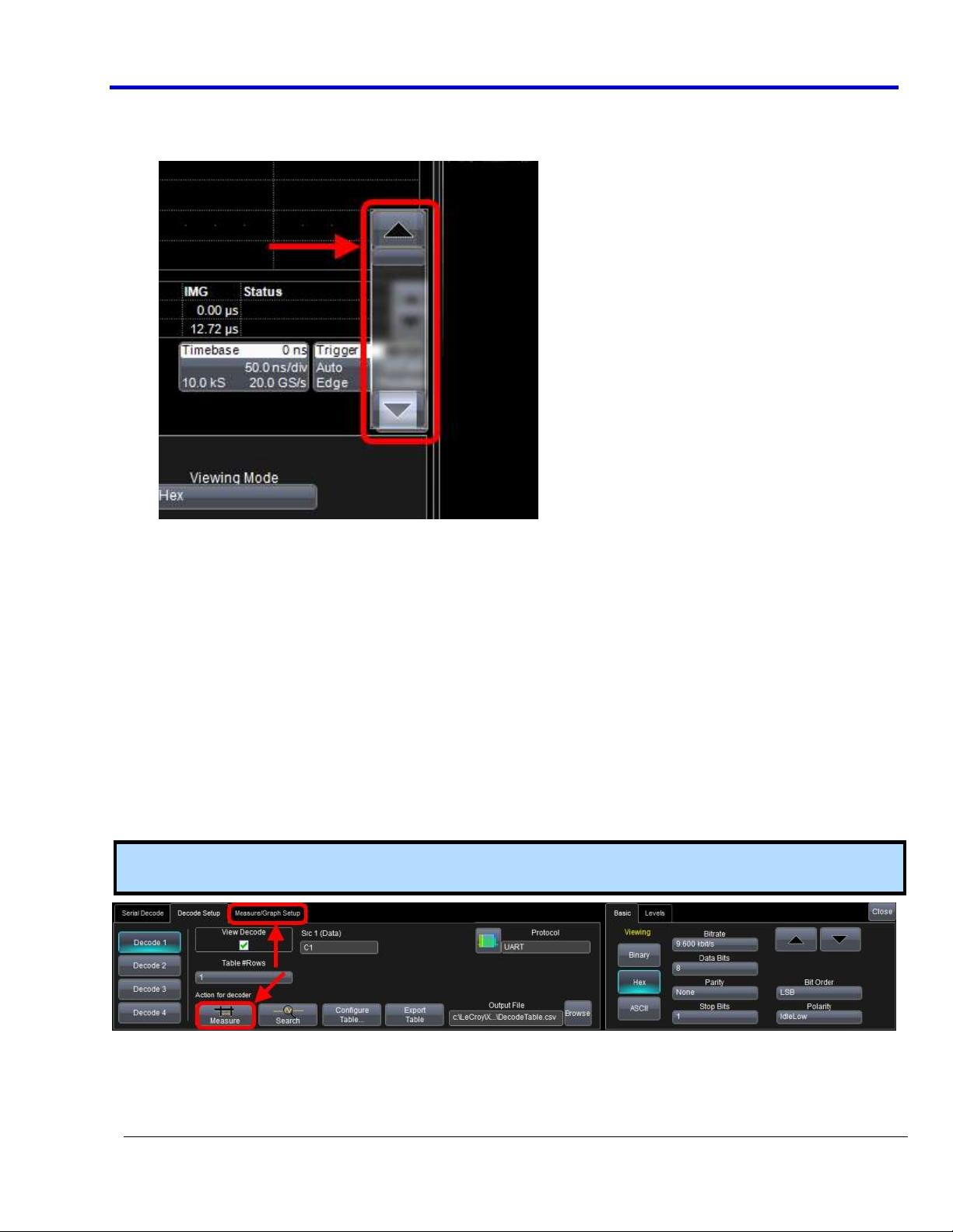
Note: If a value of only 1 - 4 rows is provided, oscilloscope models provide different solutions. Some replace
the vertical scroll bar to the right of the table with a pop-up scroll for more convenient use. Others turn the
vertical scroll bar yellow, indicating that the Adjust knob on the oscilloscope front panel can be used to
navigate table rows.
The first column heading (top left most cell of the table) bears the name of the corresponding protocol and the
cell's fill color matches the protocol color used on the grid display.
Page 20
Serial Data Debug Solutions
20
919586 RevA
Touching this colorized, first column heading opens the Decode Setup dialog. Touching any table row creates a
zoom trace of the corresponding decoded message.
The table is only shown if the View Table checkbox is marked on the Decode Setup Dialog and decoding has
occurred on the trace. Only one protocol table can be viewed at a time. As described in the previous section, the
protocol table can be configured or exported. Touching the Configure Table button on the Decode Setup Dialog
shows the View Columns pop-up similar to the following (they vary based on protocol):
Note: See Using The D Supported Protocol Toolsets (on page 14) for more information.
Page 21
Operator's Manual
919586 RevA
21
Checkboxes - Touch items to check the box and include them as table columns for a particular protocol.
BitRate Tolerance - Some protocols have a Bit Rate Tolerance setting. This can be set to any value from
0.01% to 10%. If the bit rate is outside the tolerance range set, then the calculated bit rate appears in red
text on the table.
Protocols with a wide variance of bit rates, such as I2C (which often has clock stretching) do not have this
feature.
Default - Press the Default button to reapply standard settings for a particular protocol.
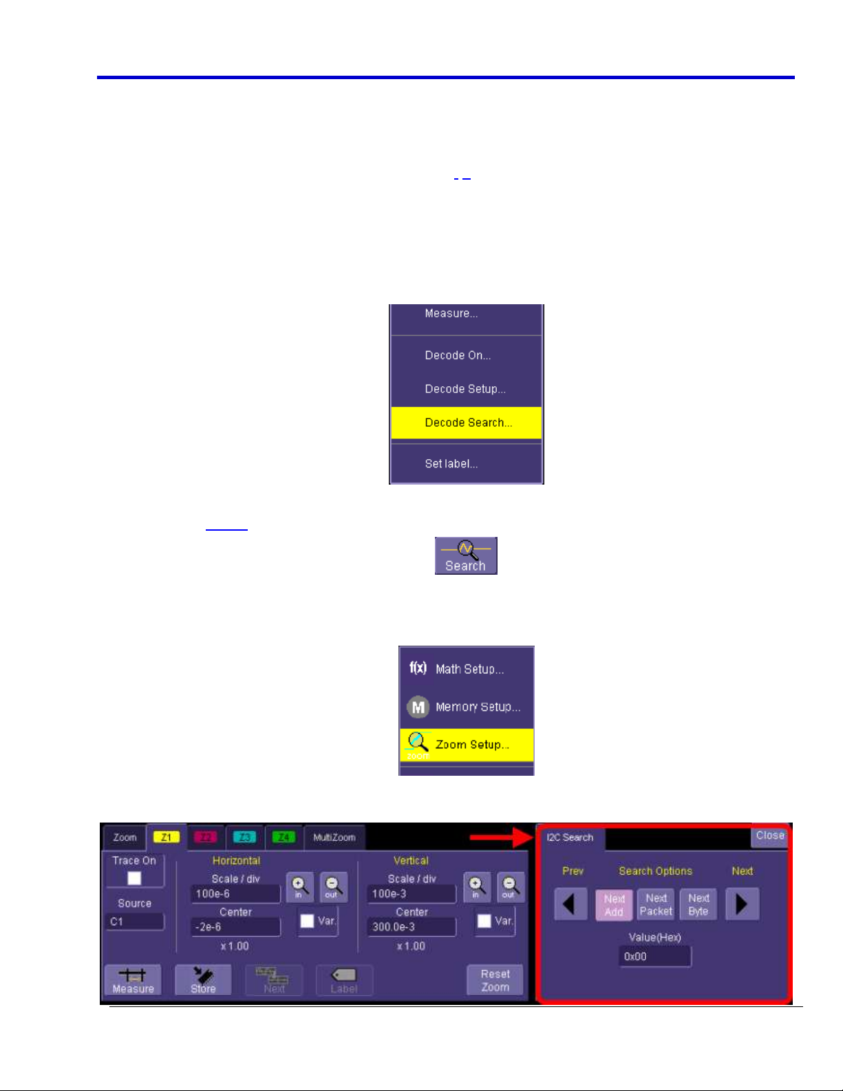
SEARCHING FOR MESSAGES
There are several ways to search for specific messages. The following are all valid ways to search messages.
Touch the decoded waveform. A pop-up dialog is shown where you can select Decode Search as follows:
OR
Touch the Search button in the Serial Decode Summary dialog box or the Decode Setup dialog box.
OR
Go to Math → Zoom Setup... from the Menu Bar to turn a Zoom ON, define its source, and search
directly.
Any of the aforementioned methods show the Zoom dialog box and a corresponding Search dialog box on the
right side.
Page 22
Serial Data Debug Solutions
22
919586 RevA
PLEASE NOTE THE FOLLOWING:
Search capabilities differ by protocol. For instance, SPI has no Address, so there is no capability to Search
by Address in SPI, while there is when searching under the I2C protocol.
Use the Search Options buttons to define the type of Search you want, enter a value in Hexadecimal
format, and use the left and right arrows to move your way from one message to the next.
When using search on a multi-data-lane protocol (PCIe), Z5 - Z8 zoom traces are used. Otherwise, single-
data-lane protocols use Z1 - Z4 zoom traces (based on the decoder assignment).
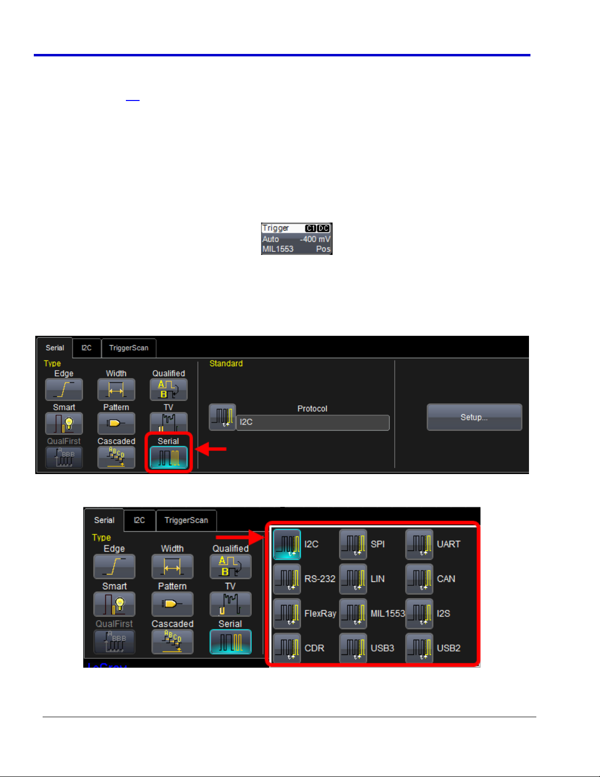
Using The T Supported Protocol Toolsets
When you acquire a LeCroy Serial Data Debug Solution equipped with a Serial Trigger, you access the specific
protocol trigger using one of the following methods:
Touch the Trigger Descriptor Box in the lower right hand corner of the oscilloscope display.
OR
Touch Trigger → Trigger Setup from the Menu Bar.
Some oscilloscope models may also have a Decode front panel button which shows the main Serial
Decode dialog when pressed.
Now, touch the Serial button on the Type section of the Trigger dialog.
Touch the Protocol field on the Standard section of the Trigger dialog and select your protocol from the choices
shown.
The focus then selects one tab to the right showing the selected Trigger Condition dialog reflecting the selected
protocol standard just selected.
Page 23
Operator's Manual
919586 RevA
23
PLEASE NOTE THE FOLLOWING:
Since each serial protocol is quite different, serial trigger conditions are also different. Detailed
information as to how a serial trigger conditions is set up for a specific protocol is covered in
corresponding protocol-specific sections of this manual.
Users approach Trigger and Decode software options differently. Some use Decode first, and then Trigger.
In fact, LeCroy has a Link To Trigger feature used to specifically tie Decoded channels to Triggers.
Currently, the protocol content in this Serial Trigger Decode and ProtoSync manual is covered in Decode,
and then Trigger order. Still, the topics are clearly covered so no matter what order you access Trigger
and Decode software, the functionality you're looking for is never far.
Accessing and Using The PROTObus MAG Supported Protocol Toolset
Certain protocol packages include the PROTObus MAG Serial Debug Toolset which provides capabilities for
making automated timing measurements using a set of provided measurement parameters. For instance, the
time between an analog signal and a corresponding serial data message can be measured with a user-definable
parameter, or an analog data value can be extracted from an embedded digital data signal or stream (digital-toanalog conversion) and displayed. Other protocol-specific measurements may also be included.
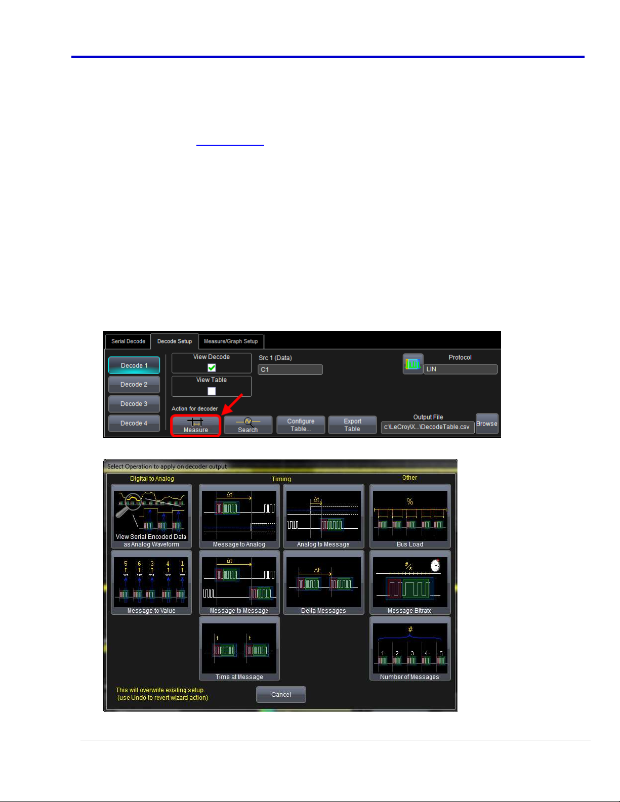
The PROTObus MAG toolset is accessed in the following manner:
1. Once you've accessed the Decode Setup dialog as explained in Accessing The D and TD Supported
Protocol Toolsets (on page 13), touch the Measure button for the desired Decode.
2. The Select operation to apply on decoder output pop-up is shown.
Page 24

Serial Data Debug Solutions
24
919586 RevA
The operations are organized in Digital to Analog, Timing, and Other columns on the pop-up for
convenience.
Choose the desired operation for your decode output by clicking the large icons on the pop-up.
Note: When accessing these parameters from the Measure button, the measurement source defaults to
DecodeX. Measurements also can be accessed using the standard Measure → Measure Setup... and Measure
dialogs. When accessed using the latter method, DecodeX has to be deliberately set as the source - instead of
the standard Signal, Math, Memory, or other trace (C1, F1, M1, etc.).
Decode Output Operation Detail
The following decode output operation explanations are organized into Digital to Analog, Timing, and Other
sections to coincide with the pop-up.
DIGITAL TO ANALOG DECODE OUTPUT OPERATIONS
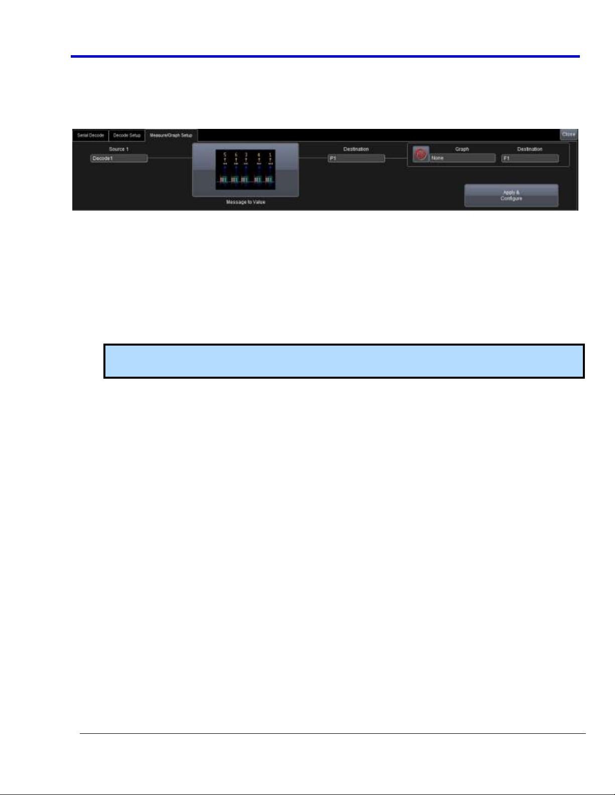
View Serial Encoded Data as Analog Waveform - Automatically sets up a Message to Value parameter
and then tracks the assigned measurement. In doing so, a Digital-to-Analog Conversion (DAC) of the
embedded digital data is performed and the digital data is displayed as an analog waveform.
Message to Value - Extract and convert a specific portion of the data/payload in the message and display
it as an analog value.
TIMING DECODE OUTPUT OPERATIONS
MsgToAnalog (Message to Analog) - Computes the time difference from a protocol message to the
crossing of a threshold on an analog signal.
AnalogToMsg (Analog to Message) - Computes the time difference from the crossing of a threshold on an
analog signal to a protocol message.
MsgToMsg (Message to Message) - Computes the time difference from one protocol message to another
protocol message.
DeltaMsg (Delta Message) - Computes the time difference between two messages on a single decoded
line.
Time@Msg (Time at Message) - Time from trigger to each protocol message (meeting specified
conditions).
OTHER DECODE OUTPUT OPERATIONS
BusLoad - Computes the load of user-defined messages on the bus (as a percent).
MsgBitrate - Computes the bitrate of user-specified messages on decoded traces.
NumMessages (Number of Messages) - Computes the number of messages which match a user-specified
definition in decoded traces.
Decode Measurement Parameters via Measure Setup
TIP: You can also access these same Decode Measurement parameters from Measure → Measure Setup... on
the menu bar.
After selecting a given Px measurement from the main Measure dialog, additional settings can be made to the
corresponding dialog as follows:
Page 25
Operator's Manual
919586 RevA
25
PX DIALOG
Source
Select the source for you parameter measurement. The source for a measurement made on a decoded
waveform should be the DecodeX applied to the channel and not the Cx channel itself.
Measure
Click in this field to select the desired measurement from the pop-up.
Protocol measurements (where applicable) can also be selected as the source for histogram, trend, or track
functions.
Actions for Px
Histo - The Histogram displays a statistical distribution of a measurement parameter. Histogram is helpful
to understand the modality of a measurement parameter, and to debug the root cause of excessive
variation.
Note: After touching Histo, Trend, or Track buttons, a Math selection pop-up is shown to select which
Math trace in which you want the results to be placed.
Trend - The Trend statistical tool visualizes the evolution of a timing parameter over time in the form of a
line graph. The graph’s vertical axis is the value of the parameter; its horizontal axis is the order in which
values were acquired. Trend is typically used for a multi-shot acquisition. Trend is analogous to a chart
recorder.
Track - The Track displays a time-correlated accumulation of values for a single acquisition. Track can be
used to plot the digital-to-analog converted (DAC) values of serial data (using the Message to Value
parameter) and compare them to a corresponding analog signal, or observe changes in timing. Track is
typically used for a single-shot acquisition. A long acquisition with many parameter measurements
analyzed with Track could provide information about the modulation of the parameter.
Now, on the main Measure dialog, additional settings can be made as follows:
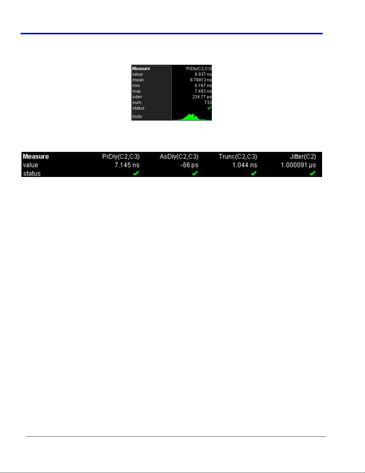
MEASURE DIALOG
Statistics
Mark the On checkbox to add the statistics of your data to the lower grid display area (same area as displayed
data for the View and Load Table checkbox).
Page 26
Serial Data Debug Solutions
26
919586 RevA
Histicons
Mark the Histicons checkbox to show or hide this additional statistical information in your lower grid display
area. The information is graphically represented a Histicon directly beneath measurement values.
Show Table
Marking the Show Table checkbox displays table data along with measurement values on the lower portion of
the grid display.
The ProtoSync Toolset
The ProtoSync Toolset Overview
Using The Full ProtoSync and PE-B Protocol Analysis and BitTracer Displays
ProtoSync provides advanced protocol analysis tools simultaneous with physical layer waveform displays. The
protocol analysis software provided is a viewing, analyzing, and trace printing subset of the software provided
with LeCroy’s hardware protocol analyzer product families.
Using the ProtoSync Protocol Analysis (available for USB, SATA, SAS, FiberChannel, or PCI Express) or ProtoSyncBT Protocol Analysis and Bit Tracer display option (available for PCI Express only), signal data can be transferred
from the oscilloscope to LeCroy’s viewing and analysis subset of LeCroy’s Protocol Analysis or BitTracer software.
SENDING DATA TO PROTOSYNC
ProtoSync works together with various LeCroy serial decode options to provide more detailed views of the
protocol. ProtoSync and serial decoders supports USB2, USB3, SAS, SATA, FibreChannel, and PCI Express, and if
the following are present on the LeCroy oscilloscope, complete views are obtainable:
Storage, Peripherals, and Interconnect Protocols Overview (on page 154)
Serial decode option for USB2, USB3, SAS, SATA, FibreChannel, or PCI Express
ProtoSync or ProtoSync-BT option
LeCroy’s Protocol Analysis software for USB2/3 (Voyager), PCI Express (PE Tracer), or
SAS/SATA/FibreChannel (Sierra)
Then, when the serial datastream is decoded, both CATC Protocols (Protocol Analysis software) and Bit Tracer
Data (PCI Express only) may also be concurrently shown on a separate window or display. Automatic transfer
and linkage between the two programs makes this possible. Selection of packets or bytes on either the
oscilloscope or ProtoSync display updates the other in real time for extremely simultaneous and comprehensive
physical layer and protocol layer debug and analysis.
PLEASE NOTE THE FOLLOWING:
The -BT suffix for ProtoSync-BT indicates BitTracer view capability and is therefore only used for the
PCIEbus decode option.
Page 27
Operator's Manual
919586 RevA
27
Label in the PCIEbus D Decode Annotation
Oscilloscope Table Display
Label in PETracer CATC Protocol View
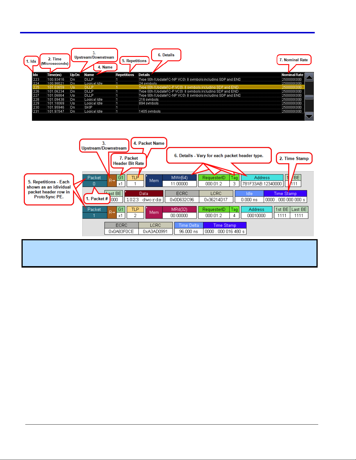
1. Idx
2. Time (µs)
3. Up/Dn
4. Name
5. Repetitions - LeCroy shows one entry
in the table and indicates the number
of repetitions.
6. Details
7. Nominal Rate
1. Packet # - Actual numbers may vary from PCIEbus D decode
annotation table in the oscilloscope to PETracer protocol
packet view since repetitions are handled differently.
2. Time Stamp - Times are likely to differ (see subsequent
note).
3. Upstream (R→) or Downstream ( R← )
4. Packet Name
5. Repetitions - PETracer protocol packet view shows each
repetition as a packet header row in the display.
6. Details - Vary for each packet header type.
7. Packet Header Bit Rate
Respective protocols in the Storage, Peripherals, and Interconnects section of this manual show how
each protocol has their own Exporter right-hand dialog used for sending specific protocol data to
ProtoSync.
The CATC Protocol View
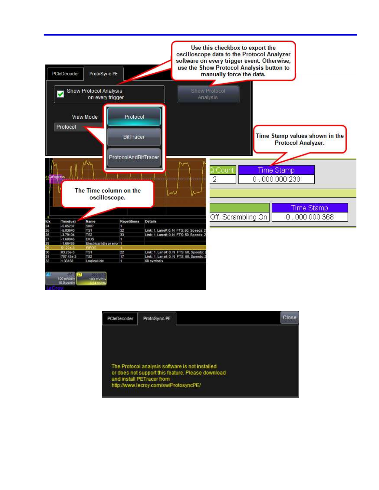
When ProtoSync is used to generate a protocol packet view of physical layer signals (in the screen-shots, using
the PCIe protocol), data packets are color-coded and shown as rows on the display. Transactions are even shown
as either upstream or downstream (shown here as R→ and R←, respectively for PCIEbus) .
Note: Viewing results look similar when using other Storage, Peripherals, and Interconnect Protocols. See
Storage, Peripherals, and Interconnect Protocols Overview (on page 154) for more information.
DECODED TABLE DATA CORRELATES TO CATC PROTOCOL DATA
While the Decode Annotation Table data is labeled and displayed differently than the CATC Protocol display,
correlation still exists between the two displays. The following table and screen-shots equates some of the
values for the PCIEbus option.
Note: Please refer to LeCroy Protocol Analyzer Software (Voyager, PE Tracer, or Sierra) user manuals at
www.lecroy.com for information regarding more specific usage when using specific supported protocols.
Page 28
Serial Data Debug Solutions
28
919586 RevA
OSCILLOSCOPE TABLE DISPLAY
PROTOSYNC PACKET VIEW
Note: Regarding Time (oscilloscope) and Time Stamp (protocol analyzer), Unless your oscilloscope trigger
delay is set to be the exact left edge of the display grid, the Protocol Analyzer Time Stamp values do not
correlate with the instrument.
Page 29
Operator's Manual
919586 RevA
29
If you don't have the Protocol Analysis software installed, this particular dialog instead shows a notification
message in place of the controls used to send your oscilloscope data to the Protocol Analyzer.
PLEASE NOTE THE FOLLOWING:
In addition to the CATC Protocol View, the Protocol Analyzer also has Link and Split views for more a
more convenient display. The Link View is not to be confused with the Link Layer which is part of the
PCIEbus D decode option and decodes everything up to (but not including) the transaction layer packet
information.
Page 30
Serial Data Debug Solutions
30
919586 RevA
Please refer to LeCroy Protocol Analyzer Software user manuals at www.lecroy.com for information
regarding more specific usage for other Storage, Peripherals, and Interconnect Protocols. See Storage,
Peripherals, and Interconnect Protocols Overview (on page 154) for more information.
The CATC Bit Tracer View - PCI Express (PCIe) Only
Based on selections made on ProtoSync Right-Hand Dialogs (located on protocol decode dialogs), ProtoSync PEB may also be used to display a CATC Bit Tracer view. This view is ideally correlated with the LeCroy 8b/10b
Decode. See 8b/10b Decode Setup Detail (on page 45) for detailed steps to send 8b/10b Decode data to
ProtoSync.
The CATC Bit Tracer view shows the Hexadecimal form of each data bit of your transferred data. Oscilloscope
Decode and ProtoSync results look like the following:
Note: Please refer to LeCroy Protocol Analyzer Software user manuals at www.lecroy.com for information
regarding more specific usage.
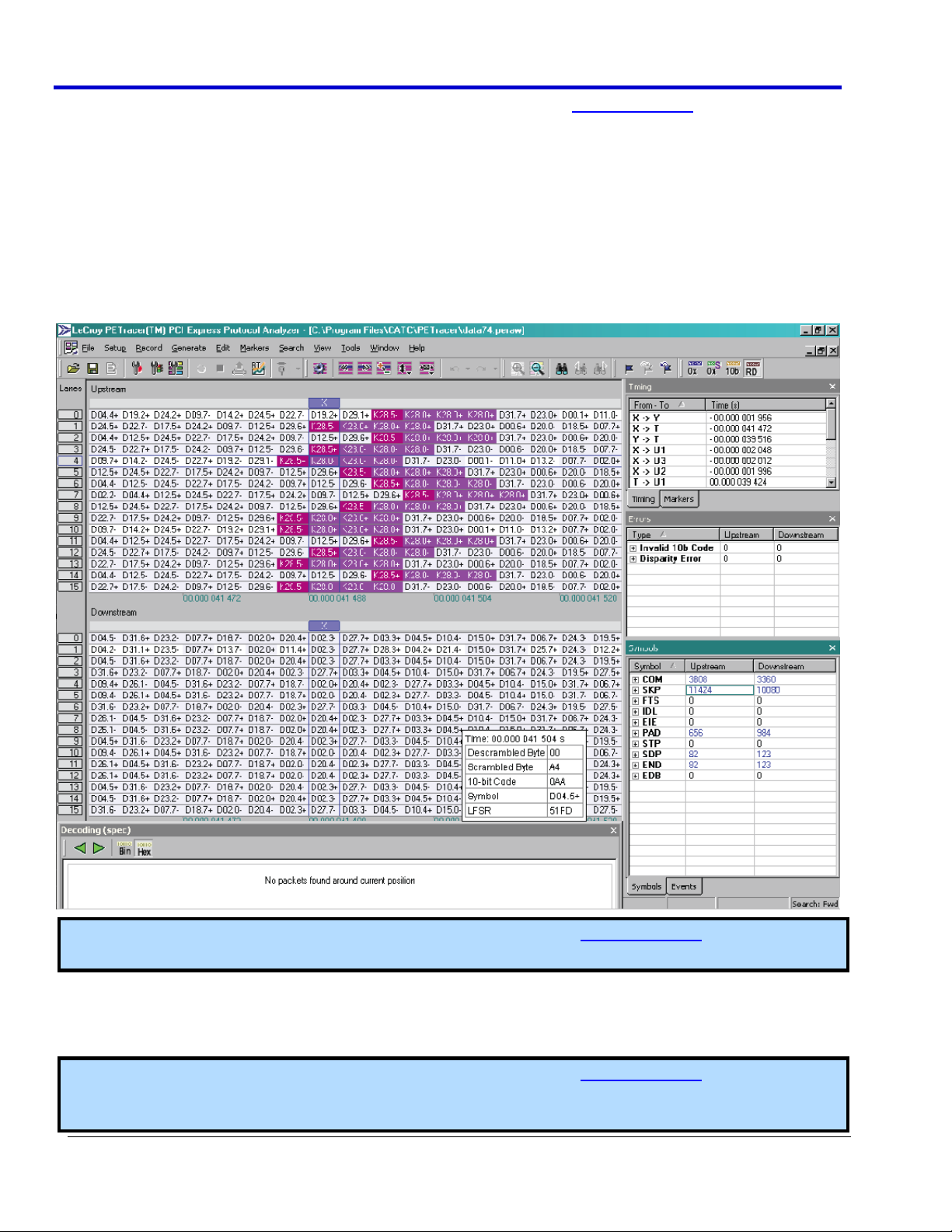
Oscilloscope and Protocol Analyzer - A Concurrent Analysis Example
This topic demonstrates the concurrent use of the Oscilloscope and Protocol Analyzer programs using PCIEbus
signals.
Note: Please refer to LeCroy Protocol Analyzer Software user manuals at www.lecroy.com for information
regarding more specific usage when using other supported protocols, see Storage, Peripherals, and
Interconnect Protocols Overview (on page 154).
Page 31

Operator's Manual
919586 RevA
31
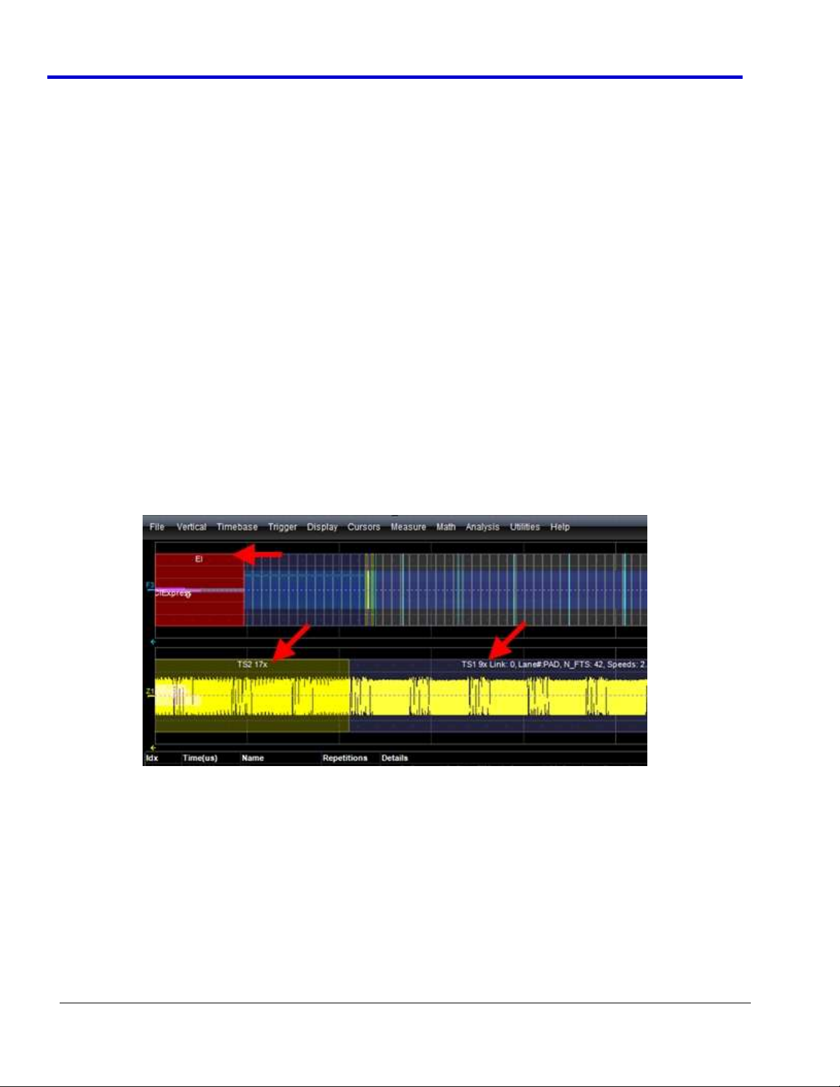
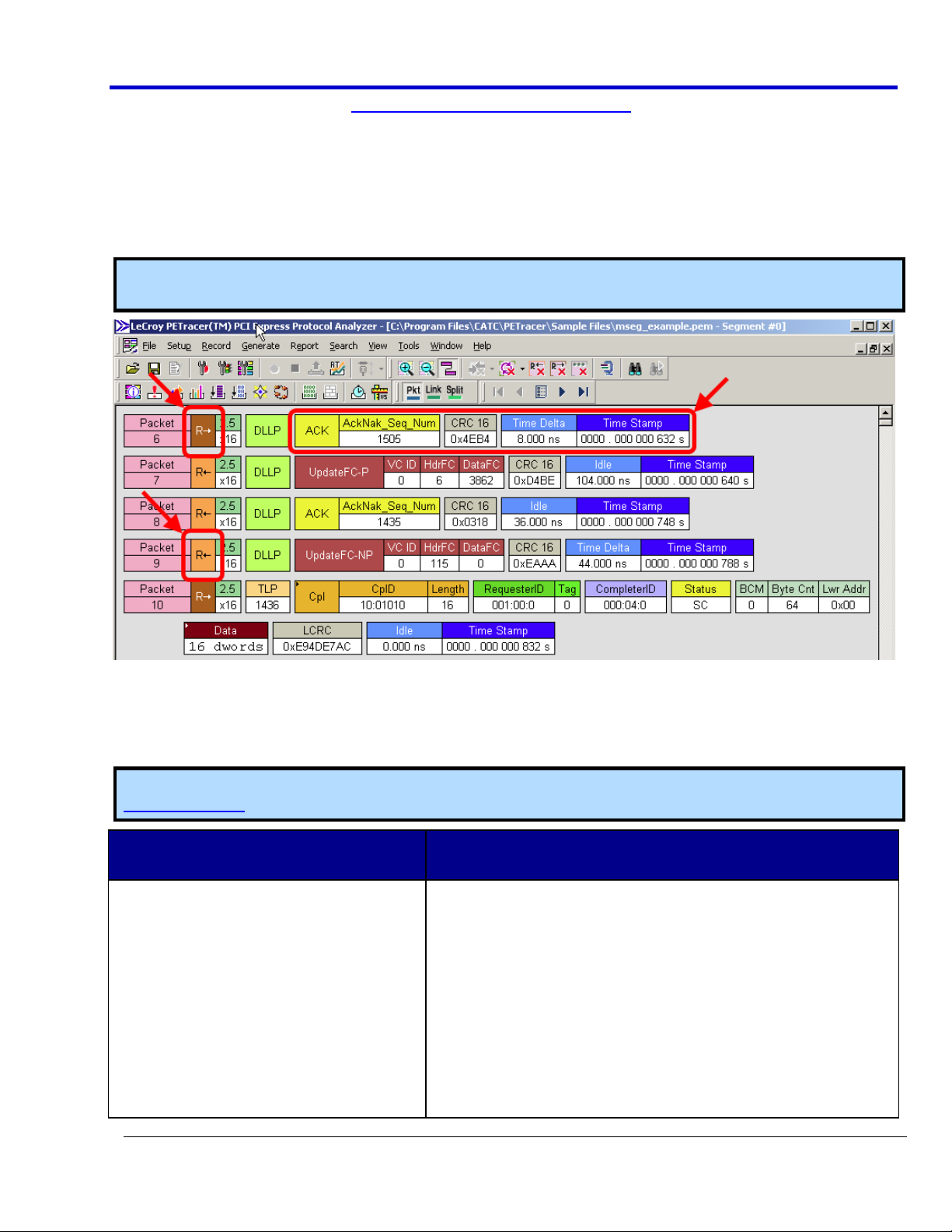
The following screen-shot shows the oscilloscope Table display along with a corresponding CATC Protocol view.
Note: Yellow arrows indicate an indirect correlation between the fields (values may not be exactly the same,
but the fields correspond to one another), while Red arrows are exact correlations between the Table display
row and the ProtoSync PE packet data.
On the oscilloscope display, if a specific table entry is touched in the PCIEbus D decode annotation table, the
physical layer waveform and decode annotation view is zoomed to just that table entry (a new zoom waveform
is shown). If there are multiple channels (lanes), or if both transmit and receive lanes are displayed, and the
protocol packet information is not exactly synchronized in time between lanes, then the lane corresponding to
the table entry is precisely zoomed and the other channels/lanes are zoomed with the same ratio as the
selected table entry.
Page 32

Serial Data Debug Solutions
32
919586 RevA
If the appropriate selections are made in the ProtoSync right-hand dialog, then simultaneously with the
oscilloscope physical layer zoom, the Protocol Analysis viewing software is opened on the same or a second
monitor (depending on your setup) and the Protocol Analysis Packet and/or CATC Bit Tracer views locate the
packet or bytes corresponding to the selected oscilloscope PCIEbus D decode annotation table entry at the top
of the Protocol Analysis or Bit Tracer display. Conversely, if a protocol packet or byte is touched in the CATC
Protocol Analysis or Bit Tracer display, the PCIEbus D decode annotation zoom shows the physical layer
waveform corresponding to that packet or byte and simultaneously highlights the table entry. This makes it
possible to quickly and easily view both the physical layer waveform, data link layer (PCIEbus D decode
annotation), the transaction layer protocol packet (CATC Protocol Analysis View of ProtoSync) or Bit/Byte view
(CATC Bit Tracer view of ProtoSync-BT).
Accessing and Using The Graphing Tools for Supported Protocols
The AudioBus (I2S) TDG package contains capability to extract digital data from a serial data message and graph
it as an analog signal - effectively performing a digital-to-analog conversion. I2S (serial digital audio) encodes
multiple channel analog sound data as digital values in a streaming serial data message. By converting this digital
data back to an analog value and graphing it as an analog audio signal, errors in data conversion, or unexpected
glitches, clips or mutes are easily viewed.
Some packages contain capability to extract digital data from a serial data message and graph it as an analog
signal - effectively performing a digital-to-analog conversion. This can be helpful to intuitively understand the
digitally encoded data that is indecipherable in a serial data message or table display. For instance, CAN
commonly encodes sensor data digitally, and CANbus TDM allows this data to be viewed as an analog plot of the
digitally encoded data values for a specific sensor versus time. I2S (serial digital audio) encodes multiple channel
analog sound data as digital values in a streaming serial data message. By converting this digital data back to an
analog value and graphing it as an analog audio signal, errors in data conversion, or unexpected glitches, clips or
mutes are easily viewed.
AudioBus Decode Setup Detail (on page 87)
PLEASE NOTE THE FOLLOWING:
The Graph package included in I
PROTObus MAG toolkit.
Ask your local LeCroy representative for more information about the Accessing and Using The PROTObus
MAG Supported Protocol Toolset (on page 23) using the Contact LeCroy for Support (on page 199) topic.
2
S TDG protocol packages, provide unique functionality separate from the
Physical Layer Eye Diagram
The FlexRaybus package provides a display of the physical layer serial data signal in an eye diagram for quick and
easy determination of physical layer abnormalities at the bit level.
For more information refer to Using the FlexRaybus Option Overview (on page 77) and FlexRaybus Physical
Layer Measurement Parameters (on page 86).
Debug Examples
Using the TD Packages: Characterize Embedded Controller Performance
USING THE TD PACKAGES: CHARACTERIZING EMBEDDED CONTROLLER PERFORMANCE USING STANDARD OSCILLOSCOPE
TOOLS OVERVIEW
The standard oscilloscope contains a number of built-in tools, such as cursors, measurement parameters, and
statistical analyzers. They can be used to characterize performance for serial data signals (just as they are also
used to characterize performance on other signals). You may want to use cursors to make single-shot timing
measurements and measurement parameters when you need to accumulate statistical data over many different
acquisitions. Measurement parameters are also helpful to determine the underlying integrity of the serial data
physical signals.
Page 33

Operator's Manual
919586 RevA
33
All TD packages provide basic tools to characterize embedded controller performance. The tools can be used on
the decoded channels, memories, zooms, functions, etc. just like they are used on any un-decoded channels,
memories, zooms, functions, etc. You also can use normal Edge or SMART Triggers on an analog channel input to
trigger the oscilloscope when a certain analog signal occurs, and then measure to a particular serial data
message using the decoded info as your guide.
In general, some of these standard tools require a fair amount of manual setup. If the goal is to make many
hundreds or thousands of measurements, you might want to consider using functionality built into the
PROTObus MAG toolset.
Note: The following examples use CANbus messages; however, similar needs exist for other serial data signals,
and the included oscilloscope tools described in the following sections can be applied in the same way.
Take the following example of an analog signal creating a burst of CAN messages:
This data was acquired over a 500 ms duration. It is likely you want to understand whether the analog signal
input to your electronic control unit (ECU) is creating the desired CAN message output from the ECU. There are a
few ways this can be done as the following topics explain.
Page 34

Serial Data Debug Solutions
34
919586 RevA
CHARACTERIZATION USING CURSORS
Use horizontal cursors to mark locations on the waveform where the time measurement should be done, and
then read the cursor values to establish the measurement. Adjust the timebase or create zooms of the decoded
trace(s) as needed in order to view the signal with enough detail. This is a good method for single-shot / single
measurements.
CHARACTERIZATION USING MEASUREMENT PARAMETERS
Measurement parameters can be used to make basic signal integrity or timing measurements of serial data
signals.
Basic parameters, such as Amplitude, Rise, Fall, Overshoot, etc. are ideal for basic signal integrity checks, which
is often all that is required for low speed (~1 Mb/s) serial data signals. Timing parameters, such as Delay, Delta
Delay, Delta Time @ Level, etc., are ideal for measuring timing from trigger to other signals (such as from an I2C
or SPI Trigger to an analog signal). SDAII is ideal for performing standard-specific physical layer measurements
on high speed serial data signals, such as PCI Express. Delta Trig Time is ideal for measuring the time between
segments of a Sequence Mode acquisition.
Please see Isolating and Analyzing Serial Bus Activity topics for more information on Sequence mode.
Amplitude - Noise and overshoot resistant measurement of the amplitude of the signal (measurement
of amplitude from Top to Base).
Base - Value of the lowermost state in a bi-modal waveform, such as an I2C, SPI, or CAN Message.
Delay - Time from the trigger to the first transition at the 50% amplitude crossing.
Page 35

Operator's Manual
919586 RevA
35
Delta Delay - Time between the 50% crossing of the first transition of two waveforms.
Delta Time @ Level - Time between selectable levels of two waveforms.
Note: Delta Time @ Level is not available on WaveSurfer Series oscilloscopes.
Delta Trig Time - The time from last trigger to this trigger (usually used in Sequence mode).
Fall (90-10), Fall 80-20, Fall@Level - Transition time on the falling edge. Three selections are available
for the user to determine at which vertical level the measurement is made.
Note: Fall@Level is not available on WaveSurfer Series oscilloscopes.
Maximum - Highest value in the input waveform.
Mean - Average of all data values.
Minimum - Lowest value in the input waveform.
Overshoot Negative - Overshoot following a falling edge.
Overshoot Positive - Overshoot following a rising edge.
Peak to Peak - Difference between the Maximum and Minimum data values.
Page 36

Serial Data Debug Solutions
36
919586 RevA
Rise (10-90), Rise (20-80), Rise@Level - Transition time on the rising edge. Three selections are available
for the user to determine at which vertical level the measurement is made.
Note: Rise@Level is not available on WaveSurfer Series oscilloscopes.
Top - Value of the uppermost state in a bi-modal waveform, such as an I2C, SPI, or CAN Message.
Gating with Measurement Parameters
Gating is available on each standard parameter. This allows you to set a measurement window in which the
parameter should be made active. This also allows you to eliminate unwanted portions of the acquisition from
your measurement.
Select gating from the Measure dialog by selecting the tab for the appropriate measurement (P1, P2, etc.), and
then setting start and stop values for the gate.
Please refer to Measure Gate in the online help for more information about Gating.
Statistics and Graphing with Measurement Parameters
Statistics and Histicons are included with nearly every LeCroy oscilloscope (Histicons are not available on
WaveSurfer Series oscilloscopes). They allow you to gather numerical and visual information on the distribution
of your various measurements.
Turn on Statistics and Histicons separately by marking their corresponding checkboxes on the Measure dialog .
Additionally, some LeCroy programs (such as JTA2) add the ability to produce larger histograms, trends, and
tracks of your measurement parameters. If you have this capability, access it through the Measurement
Parameter setup dialog (the Px tab) on the section of the dialog labeled Actions for P1.
Pass/Fail Analysis with Measurement Parameters
Set up Pass/Fail conditions by touching Analysis → Pass/Fail Setup on the menu bar.
Refer to your oscilloscope’s online help for more pass/fail setup detail.
The powerful Pass/Fail analysis using measurement parameters has a simple setup. For instance, you can define
a timing measurement, define the limits for the timing measurement, and then run the oscilloscope in a Normal
trigger mode, capturing thousands of measurement events.
What's more is Pass/Fail can then be used to save the Waveform in the event of a Fail, or send an email in the
event of a fail.
Page 37

Operator's Manual
919586 RevA
37
Isolating and Analyzing Serial Bus Activity
ISOLATING AND ANALYZING SERIAL BUS ACTIVITY OVERVIEW
The combination of Serial Data Triggering, Decoding, and normal oscilloscope features is a powerful mixture of
tools that can make it very easy to find latent Serial Data hardware or software problems in your circuit. No
longer is the oscilloscope a tool just for the hardware engineer. Now, software engineers can also easily visualize
the Serial Data signals and relate them to programming code and operation. Decode and Trigger toolsets allow
hardware and software Engineers to speak the same language when it comes to system debugging and
performance checking.
For more detailed explanations of Decode and Trigger toolsets refer to Technical Explanation of Serial Decode
and Trigger (on page 12). Some common Serial Data analysis needs and methods are discussed in the following
topics.
CAPTURING LONG PRE-TRIGGER TIMES
LeCroy oscilloscopes are available with optional, very long acquisition memory. When decoding low speed (~1
Mb/s) serial data signals, it is possible to set the sample rate to a minimum value (such as 5 MS/s) and capture
and decode seconds of serial data traffic, even with standard 10 Mpt/ch memories. When decoding high speed
(Gb/s) serial data signals, higher sample rates are needed, which reduces capture time, but many LeCroy
oscilloscopes suitable for these serial data rate signals have optional very long acquisition memories that can be
used to achieve long capture times.
If necessary the capture can be 100% pre-trigger, 100% post-trigger, or something in between.
1. First, adjust Pre-Trigger and Post-Trigger time using the Delay knob on the oscilloscope’s front panel.
2. Now, optimize your Sample Rate or Memory Length by accessing the Horizontal Dialog on your
oscilloscope and selecting either Set Maximum Memory mode or Fixed Sample Rate mode.
If you choose to Set Maximum Memory, you can decrease the memory usage so you do not
sample at too high a sample rate (too high a sample rate slows down the decoding algorithm).
Then, adjust your timebase setting to a length sufficient to capture the event.
Note: Make sure your timebase setting and memory length combined do not result in too low a
sample rate. Otherwise, adequate capture and decode is not performed.
More commonly, you will probably choose to fix the sample rate to a specific value providing the
necessary oversampling required to capture your Serial Data messages (at least 4X the bit rate).
Also, it affords a high enough sample rate to capture transients you may want to see on Serial Data
and analog signals (at least 2X the frequency of any expected transients, preferably 10X).
Note: Reference your oscilloscope’s online help for more information about the core oscilloscope settings
mentioned earlier in this topic.
REPEATEDLY TRIGGERING AND SAVING THE DATA TO A HARD DRIVE
You may wish to set up your oscilloscope to capture a short or long memory acquisition for a certain trigger
condition, and then save data to a hard drive or memory stick whenever the trigger condition is met.
Note: While this can be easily done in most LeCroy oscilloscopes, realize there is significant trigger dead time
while using this method. Minimize dead time by using the method described in the following Repeated
Triggering and Storing all Triggers (Sequence Mode) topic.
Repeatedly trigger and save the data to a hard drive by doing the following:
1. First, set up your desired serial data (or other) trigger condition (see corresponding protocol sections
previously covered in this documentation for details).
Page 38

Serial Data Debug Solutions
38
919586 RevA
2. Now, choose File → Save Waveform from the menu bar. The Auto Save dialog is shown where you can
set up the Save Waveform conditions.
As the previous screen-shot shows, you can disable the Auto Save function by clicking the OFF button. Or,
select WRAP where Auto Save occurs until the hard drive is filled, and then discards the oldest data in
order to write the newest data. Lastly, select FILL which Auto Saves until the hard drive is filled and then
stops.
PLEASE NOTE THE FOLLOWING:
Be sure to choose a Binary file format if you wish to recall the traces into a LeCroy oscilloscope for later
analysis.
Even though the LeCroy oscilloscope hard drives are very large, it is a good idea to make sure your trigger
condition is set correctly before running your acquisitions.
REPEATEDLY TRIGGERING AND STORING ALL TRIGGERS (SEQUENCE MODE)
LeCroy oscilloscope’s have a powerful Sequence Mode function which stores all triggered events by minimizing
the dead time between triggers to < 800 nanoseconds. It's ideal for finding repetitive problem causes on your
serial data buses or associated signals. (Sequence Mode is not available on WaveSurfer Series oscilloscopes.)
Sequence Mode uses long acquisition memory divided into “segments.” As triggered events are acquired, they
are stored in acquisition segments for recalling at a later date. The length of each sequence mode acquisition
segment and the total number of segments allowed is roughly determined by the total acquisition memory in
the oscilloscope. For instance, on a WaveRunner Xi you can acquire 10,000 segments each a maximum of 625
samples long, or 10 segments each a maximum of 1.25 megasamples long, or something in between. Different
acquisition memory lengths have different ranges of segments and segment lengths. You can define any number
of segments from 2 to the maximum for that memory length (refer to your oscilloscope’s specifications for
details) and any length of segment (provided there is sufficient acquisition memory). After acquisition of all
segments is complete, you can recall them one-by-one and view them in decoded format on the oscilloscope
screen.
Acquisition dead time is kept to a minimum because there are no operations performed during the acquisition.
All data for each triggered event is written only into high-speed acquisition memory. Until the entire sequence is
completed, there is no updating of the oscilloscope display, or other operations causing unnecessary dead time.
It's ideal for situations where you cannot take a chance on losing data.
In the following example, we have only acquired Channel 1 in sequence mode. Keep in mind, additional analog
or other signals can also be acquired (if desired or necessary) in order to perform a more proper analysis.
1. Touch the Timebase trace descriptor label to open the Timebase dialog.
Page 39

Operator's Manual
919586 RevA
39
2. In the Sampling Mode area, select Sequence Mode.
Touch the tab labeled Sequence that is now shown next to the Timebase tab.
3. On the Sequence tab, select the Display Mode and select the Number of Segments Displayed at one
time.
Note: If you have acquired more segments than you can display at one time, use the Starting at field to
specify a segment at which to begin the display.
Serial Trigger Setup for Specific Events
At this point, the Serial Trigger is now set up to capture the desired event. The following sections provide eventbased setup explanations.
You can trigger on a specific address or data value and capture long pre-trigger time to determine what
precedes the message.
Our example here uses an I2C Start trigger. Start the sequence mode acquisition by pressing the front
panel SINGLE trigger button. Each time the trigger condition is met, the TRIG’D light on the front panel
flashes.
Page 40

Serial Data Debug Solutions
40
919586 RevA
When you’ve acquired the set number of segments, the trigger STOPS and a display similar to the
following is shown (this is a 50 segment acquisition in Mosaic display mode).
You can display an individual segment separately from the main channel display by selecting Math →
Math Setup... from the menu bar. Choose a math trace to define as a Segment (in this case, F1 is defined
as a Segment of C2). Use the channel that your serial data was acquired on (in this case Channel 2) as a
Source.
Page 41

Operator's Manual
919586 RevA
41
Display the trace by checking the TRACE ON checkbox. Select the segment for viewing by touching the
Select tab and selecting a segment using the pop-up keypad or the front panel Adjust knob.
You can view decoded data on the individual segment by setting up the Decode to use the Math trace as
the source for Data (in this case F4 is the Source).
Page 42

Serial Data Debug Solutions
42
919586 RevA
If you wish to change the segment that is decoded, just select a new segment from the Math trace dialog
(as shown in the previous step).
Note: Conserve display space by turning off the Channel and only select the segment you wish to view as the
following screen-shot shows.
Page 43

Operator's Manual
919586 RevA
43
You can view the timestamps for each segment by selecting Vertical → Channels Status from the menu
bar and selecting Time on the Show Status For section of the dialog as shown.
Page 44

Serial Data Debug Solutions
44
919586 RevA
A display of timestamp information for each segment in the sequence acquisition is then shown (as
follows).
Note: Ten timestamps fit on the display at one time. Choose which segments to display by using the
Select Segment control. You can also page through the segments one at a time by using the Adjust knob
on the front panel.
Page 45

Operator's Manual
919586 RevA
45
Serial Pattern Encoding Schemes - 8b/10b
Serial Pattern Encoding Schemes Overview
8b/10b
8b/10b encoding is not a protocol, but a widely used method to encode 8-bit words within a 10-bit symbol, or
character. The extra bits are used to ensure the long-term ratio of 1s and 0s transmitted is 1:1, ensuring the
serial data encoding is DC free. Serial data standards using 8b/10b encoding also define special symbols or
control characters indicating start or end-of-frame, skips, link idles, or other protocol-specific non-data
information. Many high-speed serial data standards, such as PCI Express, SATA, SAS, Fibre Channel, etc. use
8b/10b as the underlying encoding method below the protocol layer. Each standard defines their own set of
special symbols or control characters.
The remainder of this section provides a brief introduction to the various protocols available as part of LeCroy's
Serial Data Debug Solutions for convenience.
Using the 8b/10b Option
Using the 8b/10b Option Overview
8b/10b encoding is not a protocol, but a widely used method to encode 8-bit data words within a 10-bit symbol,
or character. The extra bits are used to ensure the long-term ratio of 1s and 0s transmitted is 1:1; ensuring the
serial data encoding is DC free. Also, any bit transmission longer than five consecutive 1s or 0s is prohibited,
which limits the requirements for the lowest required bandwidth in the serial data transmission channel.
Furthermore, an additional requirement is that the difference in number between 1 bit and 0 bit transmissions
is never more than two. Theoretically, there are 1024 (2 to the 10th power) different 8b/10b encoded bytes
possible, far fewer are allowed based on these aforementioned rules.
In order to maintain the DC-free nature of the signal, a running disparity counter is kept for each byte. This
count reflects the bias of 1s or 0s from the transmitted byte, and the 8b/10b encoder makes use of the value of
this running disparity counter to determine whether to encode the next byte as a +1 or -1 running disparity so as
to keep the overall DC bias of the transmitted signal at zero. Thus, there are two valid bit sequences for any
byte, depending on the running disparity used. The LeCroy 8b/10b decoder takes all this into account so that the
user doesn't have to.
Serial data standards that use 8b/10b encoding also define special symbols or control characters that indicate
start or end-of-frame, skips, link idles, or other protocol-specific non-data information. These are commonly
referred to as primitives. Many high speed serial data standards, such as PCI Express, SATA, SAS, Fibre Channel,
etc. use 8b/10b as the underlying encoding method below the protocol layer. Each standard defines their own
set of primitives. Primitives convey more basic information than contained in a full protocol decode, but they
can be valuable as well for debugging or quality control purposes.
8b/10b Decode Setup Detail
For general information about using controls shown on the main Serial Decode dialog, refer to Accessing The D
and TD Supported Protocol Toolsets (on page 13).
8B/10B DECODE BASIC, FILTER, AND DVPT RIGHT-HAND DIALOGS
Access the Serial Decode dialog by touching Analysis → Serial Decode on the menu bar.
Touch the corresponding Setup... button for your decode. The Decode Setup... along with corresponding righthand dialogs are shown. Select the 8b/10b Decode protocol from the Protocol control.
Additional setup details for sending 8b/10b Decode to ProtoSync involve selecting a single source (trace) for the
data, and configuring the right-hand dialogs for Basic and Filter.
Page 46

Serial Data Debug Solutions
46
919586 RevA
The Basic Right-Hand Dialog
The 8b/10b Basic Right-Hand dialog provides detailed fields and setup conditions as follows:
Use the Viewing buttons to Choose from Hexadecimal or Symbolic. Hexadecimal decode viewing
automatically ignores the non-data bits in the 10-bit symbol/character and returns a Hexadecimal value
for the 8 data bits only. Symbolic decode viewing provides a protocol-specific view of the 10-bit symbol,
using the Protocol selection to the right (and described next).
Note: Regardless of your choice here, both are shown on the table display. This selection determines
which base is used in trace annotations on the display grid.
Protocol - Make a selection from the standards available in this field. Each standard has a pre-defined
translation of the 10-bit symbol into a character name (primitive) - reference the latest version of that
particular standard for a detailed translation table.
Primitive File - Selecting Others from the Protocol field enables this field which can be used to provide
your own definition file for primitives and even name default filters.
Example primitive file for SATA.
Page 47

Operator's Manual
919586 RevA
47
The Filter Right-Hand Dialog
Use this dialog to specify which primitives for the protocol standard (selected from the basic Right-Hand Dialog,
previously) are Decoded or Filtered out of the results.
Using 8b/10b Hi-Speed Serial Triggers on Zi Oscilloscopes
SOMETIMES REFERRED TO AS SERIAL TRIGGER
High Speed Serial Trigger Setup
Source Setup
Encoding
Entering Binary, Hexadecimal, and 8b/10b Trigger Patterns
WARNING
Prevent serial trigger module damage and never apply external voltages to the clock and data output
connectors.
SDA 7 Zi and 8 Zi model oscilloscopes include a serial pattern trigger and a Clock and Data Recovery module.
PLEASE NOTE THE FOLLOWING:
SDA 725 Zi and SDA 735 Zi model oscilloscopes include the WavePro Medium Speed Serial Trigger module
option (WPZi-MSPT). The CDR range is 100 Mb/s - 1.25 Gb/s.
SDA 740 Zi and SDA 760 Zi model oscilloscopes include the WavePro High Speed Serial Trigger module
option (WPZi-HSPT). The CDR range 100 Mb/s - 2.7 Gb/s, 3.0, 3.125 Gb/s.
All of the SDA 8 Zi and Zi-A model oscilloscopes include the WaveMaster High Speed Serial Trigger
module option (WM8Zi-HSPT). The CDR range 100 Mb/s - 2.7 Gb/s, 3.0, 3.125 Gb/s.
The CDR module is built into the instrument and is accessible through the channel 4 input. The signal on channel
4 is always present at the input to the serial pattern trigger module. The serial trigger also includes two outputs
located on the front panel, to the right of the channel 4 input. These two SMA connectors allow access to the
recovered clock and data signals from the serial trigger module for signals up to 2.7 Gb/s. The signals at these
connectors are nominally zero mean with a peak-to-peak amplitude of 330 mV.
Note: The recovered clock and recovered data output signals are not available for 3 and 3.125 Gb/s.
Page 48

Serial Data Debug Solutions
48
919586 RevA
HIGH SPEED SERIAL TRIGGER SETUP
Access the High Speed Serial trigger dialog by touching the Trigger descriptor label, and then the Serial Trigger
button.
The High Speed Serial trigger dialog is then shown. Notice how the dialog is divided into three sections for
Source Setup, Encoding, and Trigger Patterns.
The remainder of this topic explains these sections and their controls.
SOURCE SETUP
Click the Compute Bitrate button to find the bitrate of your signal and lock the CDR on the incoming signal. The
Serial Data input must be present on Channel 4 in order to use the Serial Trigger. Verify that the lock is closed
and the correct bitrate has been found before proceeding.
Note: For SDA 820 Zi or higher bandwidth oscilloscopes, channel 3 is used for serial trigger input when
channels 3 and 4 are operating in DBI mode.
The PLL section then indicates that the Phased Locked Loop has locked to your bitrate.
ENCODING
Choose Binary, Hex, or Symbolic (8b/10b) formats for providing your trigger pattern values.
PLEASE NOTE THE FOLLOWING:
Trigger pattern value encoding formats can be changed after providing your entry. Just click on the
format and the conversion is done for you. For example, provide a Hex value on which you would like to
trigger, click the Binary button, and the Hex value is automatically converted into Binary.
Conversions may be done from Hex to Binary, Binary to Hex, Symbolic (8b/10b) to Hex or Binary -
however, Hex or Binary to Symbolic (8b/10b) is not supported.
TRIGGER PATTERNS
Now, set the Data Pattern on which to trigger. Binary and Hex data patterns are entered similarly, while
Symbolic 8b/10b differs.
Entering Binary and Hex Data Patterns
You can provide 2 data patterns (80 bit) for triggering. If 2 are used, the system triggers on data pattern 1
OR 2 (indicated on the Trigger On section of the dialog).
Provide your values by typing directly into the Data Value field, or double-click the field and use the
corresponding pop-up keypad.
Note: Notice how the virtual keypad shown after double-clicking the Data Value field corresponds with
the selected encoding format.
The Highlight Pattern check box may be used to shade the portion of the waveform on the grid display
where your data value occurs.
Page 49

Operator's Manual
919586 RevA
49
Char 7
Char 6
Char 5
Char 4
Char 3
Char 2
Char 1
Char 0
Valid Trigger Sequence
XXX.X
XXX.X
K28.5
D10.3
XXX.X
XXX.X
XXX.X
XXX.X
Invalid Trigger Sequence
K28.5
XXX.X
XXX.X
XXX.X
XXX.X
XXX.X
XXX.X
D10.3
Entering Symbolic 8b/10b Data Patterns
When Symbolic Encoding is selected:
The tab on the High Speed Serial trigger dialog changes to 8B10B
A Running Disparity section is added to the dialog with choices for Positive, Negative, or Either.
A Trigger Pattern section designed for 8b/10b is shown.
Running Disparity selections directly affect the Trigger Pattern fields in a corresponding manner. The Positive
Running Disparity button activates only the Positive Running Disparity field, the Negative activates only the
Negative, and Either activates both. When using Both Running Disparity Trigger Patterns, the system triggers on
the Positive OR the Negative (as indicated on the Trigger On section of the dialog when the values are provided).
Provide your 8b/10b Character values in the Char 7 through Char 0 fields. Provide values by typing
directly into the Data Value field, or double-click the field and use the 8b/10b pop-up keypad.
Note: For more information on specific 8b/10b characters refer to the Encoding Table Reference (on
page 50) topic.
Due to the fact that 8b/10b is a dual-parity protocol, triggering on non-consecutive 8b/10b amounts with
"don't care" values in between is not possible. This is because preceding characters affect subsequent
parity bits.
For Example:
The Highlight Pattern check box may be used to shade the portion of the waveform on the grid display
where your data value occurs.
Helpful Trigger Pattern Tools
Binary and Hex Data Patterns have a group of buttons to the right of the High Speed Serial trigger dialog
and can be used to quickly set the pattern to all 0s, all Xs, all 1s, or an inversion of the value provided in
the field.
Saving and Recalling Serial Data Patterns into the Trigger keeps you from having to repeatedly re-enter
them. The serial trigger pattern is also stored in the setup file whenever you save the panel file through
the File → Save Setup dialog. So, the trigger pattern can be recalled simply by recalling the corresponding
panel file. However, the panel setup file saves the entire state of the instrument, which may not always
be desirable. In such cases, use this Save/Recall control to save the Binary, Hex, or Symbolic pattern alone
into CDR (Clock Data Recovery) Pattern.lss files.
Page 50

Serial Data Debug Solutions
50
919586 RevA
Input
RD = -1
RD = +1
Input
RD = -1
RD = +1
EDCBA
abcdei
EDCBA
abcdei
D.00
00000
100111
011000
D.16
10000
011011
100100
D.01
00001
011101
100010
D.17
10001
100011
D.02
00010
101101
010010
D.18
10010
010011
D.03
00011
110001
D.19
10011
110010
D.04
00100
110101
001010
D.20
10100
001011
D.05
00101
101001
D.21
10101
101010
D.06
00110
011001
D.22
10110
111010
D.07
00111
111000
000111
D.23 †
10111
111010
000101
D.08
01000
111001
000110
D.24
11000
110011
001100
D.09
01001
100101
D.25
11001
100110
D.10
01010
010101
D.26
11010
010110
D.11
01011
110100
D.27 †
11011
110110
001001
D.12
01100
001101
D.28
11100
001110
D.13
01101
101100
D.29 †
11101
101110
010001
D.14
01110
011100
D.30 †
11110
011110
100001
D.15
01111
010111
101000
D.31
11111
101011
010100
K.28
11100
001111
110000
Input
RD = -1
RD = +1
Input
RD = -1
RD = +1
HGF
fghj
HGF
fghj
D.x.0
000
1011
0100
K.x.0
000
1011
0100
D.x.1
001
1001
K.x.1 ‡
001
0110
1001
D.x.2
010
0101
K.x.2 ‡
001
1010
0101
D.x.3
011
1100
0011
K.x.3
011
1100
0011
D.x.4
100
1101
0010
K.x.4
100
1101
0010
D.x.5
101
1010
K.x.5 ‡
001
0101
1010
D.x.6
110
0110
K.x.6 ‡
001
1001
0110
D.x.P7 †
111
1110
0001
D.x.A7 †
111
0111
1000
K.x.7 † ‡
111
0111
1000
Encoding Table Reference
For convenience, the following standard tables provide data for 5b/6b, 3b/4b, and Control Symbols.
5B/6B
Table 3-2.† Same code used for K.x.7
3B/4B
Page 51

Operator's Manual
919586 RevA
51
Input
RD = -1
RD = +1
HGF EDCBA
abcdei fghj
abcdei fghj
K.28.0
000 11100
001111 0100
110000 1011
K.28.1 †
001 11100
001111 1001
110000 0110
K.28.2
010 11100
001111 0101
110000 1010
K.28.3
011 11100
001111 0011
110000 1100
K.28.4
100 11100
001111 0010
110000 1101
K.28.5 †
101 11100
001111 1010
110000 0101
K.28.6
110 11100
001111 0110
110000 1001
K.28.7 ‡
111 11100
001111 1000
110000 0111
K.23.7
111 10111
111010 1000
000101 0111
K.27.7
111 11011
110110 1000
001001 0111
K.29.7
111 11101
101110 1000
010001 0111
K.30.7
111 11110
011110 1000
100001 0111
Table 3-3.† For D.x.7, the Primary (D.x.P7) or Alternate (D.x.A7) encoding must be selected in order to avoid a run of five
consecutive 0s or 1s when combined with the preceding 5b/6b code. Sequences of five identical bits are used in comma
codes for synchronization issues. D.x.A7 is only used for x=17, x=18, and x=20 when RD=−1 and for x=11, x=13, and x=14
when RD=+1. With x=23, x=27, x=29, and x=30, the same code forms the control codes K.x.7. Any other x.A7 code can't
be used as it would result in chances for misaligned comma sequences.
‡ The alternate encoding for the K.x.y codes with disparity 0 allow for K.28.1, K.28.5, and K.28.7 to be "comma" codes
that contain a bit sequence that can't be found elsewhere in the data stream.
CONTROL SYMBOLS
Table 3-4.† Within the control symbols, K.28.1, K.28.5, and K.28.7 are "comma symbols." Comma symbols are used for
synchronization (finding the alignment of the 8b/10b codes within a bit-stream). If K.28.7 is not used, the unique comma
sequences 0011111 or 1100000 cannot be found at any bit position within any combination of normal codes.
‡ If K.28.7 is allowed in the actual coding, a more complex definition of the synchronization pattern than suggested by †
needs to be used, as a combination of K.28.7 with several other codes forms a false misaligned comma symbol
overlapping the two codes. A sequence of multiple K.28.7 codes is not allowable in any case, as this would result in
undetectable misaligned comma symbols.
K.28.7 is the only comma symbol that cannot be the result of a single bit error in the data stream.
SOURCE
Peter A. Franaszek, Albert X. Widmer, et al. "Byte oriented DC balanced (0,4) 8B/10B partitioned block
transmission code." US Patent 4486739. December 4, 1984.
Page 52

Serial Data Debug Solutions
52
919586 RevA
8b/10b Decode Search
The 8b/10b Search right-hand dialog appears when the Zoom dialog is shown.
Use the Prev and Next buttons to advance through Primitive, Code, or Error occurrences.
With Next Primitive selected, you can select a specific message based on the protocol chosen on the
Basic Right-Hand dialog, see Decode Setup Detail (on page 45).
When Next Code is selected, you can mark the Don't Care checkbox, or unmark it to enable the Code
control and provide a specific code value.
Page 53

Operator's Manual
919586 RevA
53
Number of Lines
Data rate
Synchronous or Asynchronous
2
Up to 3.4 Mb/s
Synchronous
Number of Lines
Data rate
Synchronous or Asynchronous
3
Up to ~50 Mb/s
Synchronous
Number of Lines
Data rate
Synchronous or Asynchronous
1
Up to 1 Mb/s (typical)
Asynchronous
Number of Lines
Data rate
Synchronous or Asynchronous
1
Up to 57.6 kb/s (typical)
Asynchronous
General Purpose Embedded Protocols
General Purpose Embedded Protocols Overview
I2C
I2C is a standardized protocol created by Philips with a documented technical specification.
NXP (formerly Philips Semiconductors) provide a full description of the standard at www.standardics.nxp.com.
SPI
SPI was popularized by Motorola but is not standardized, per se - there are a variety of variants with the
differences characterized by how data is clocked, whether data is MSB or LSB format, and whether it is multislave or single-slave.
While the SPI has no formal standard, information is often included in the technical documentation for the
microprocessor supporting the protocol.
UART
UART is a generic backbone for many proprietary serial data protocols (too numerous to mention) each with
different physical layers.
UART has no formal standard. The protocol evolved from mechanical rotating teletypewriter devices. Formats
were formalized with the advent of the first electronic computers.
RS-232
RS-232 is a special case of UART, with a more defined protocol and specific physical layer.
The physical layer is defined in the Electronic Industries Association (EIA) EIA-RS-232-C and the
Telecommunications Industry Association (TIA) TIA-232-F. Its protocol layer is not specified; however, UART is
commonly implemented. Resources can be found at www.eia.org and www.tiaonline.org.
Using the I2Cbus Option
Using the I2Cbus Option Overview
Both I2Cbus D and TD options contain powerful software algorithms to extract serial data information from
physical layer waveforms measured on your oscilloscope. The extracted information is overlaid (annotated) on
the actual physical layer waveforms, and color-coded to provide fast, intuitive understanding.
The I2Cbus TD option contains a very powerful and flexible trigger, but it is also very easy to set up for basic
triggering. The I2Cbus TD option contains a conditional I2C DATA trigger to select a range of DATA values to
trigger on, not just a single DATA value.
Page 54

Serial Data Debug Solutions
54
919586 RevA
Oftentimes, I2C utilizes DATA bytes to specify sub-addresses for accessing memory locations in EEPROMs.
Conditional DATA trigger allows triggering on a range of DATA bytes corresponding with reads or writes to
specific sub-address memory blocks in the EEPROM. It can also aid in monitoring DATA outputs from I2C- based
sensors, such as analog-to-digital converters, and triggering when DATA is outside a safe operating range. In
both cases, verifying proper operation becomes a simple task. Other powerful and user-friendly features
included in I2Cbus TD trigger include:
Ability to define and ADDR or DATA condition in either Binary or Hexadecimal (Hex) formats.
Ability to define an ADDR condition in binary with the DATA condition defined in hexadecimal so as to
trigger on a range of ADDR values using Don’t Care bits.
FRAME LENGTH trigger setups.
EEPROM trigger setups to trigger on up to 96 bits (12 bytes) of DATA at any location within an I
at a user-defined location in a 2048 byte window.
All permutations of Read, Write, or R/W Don’t Care conditional setup for 7 and 10-bit addresses.
For any I
2
C message trigger, select whether an ACK condition should be ACK, NO ACK, or DON’T CARE. You
can choose to trigger on a NO ACK condition by itself, or as part of a more complex ADDR/DATA trigger.
If you are not familiar with or are just learning about I2C, start by using the simplest trigger conditions (Start,
Stop, ReStart, NoAck) to gain confidence, and then set up simple ADDR only conditions. When you are confident
with understanding I2C operation, set up an ADDR+DATA condition with a condition of “DATA =”. Then, try
different setups using other DATA conditions (>, <, INRANGE, etc.). Lastly, experiment with the EEPROM trigger
setup, which provides the most flexibility by allowing location of data, with conditions, within specific bytes of a
long sequence of DATA bytes.
2
C frame or
Note: Ask your local LeCroy representative for more information about any Serial Data Debug Solution
Protocols or Toolkits using the Contact LeCroy for Support (on page 199) topic.
I2C Decode Setup Detail
For general information about using controls shown on the main Serial Decode dialog, refer to Accessing The D
and TD Supported Protocol Toolsets (on page 13).
I2C BASIC AND LEVELS RIGHT-HAND DIALOGS
Access the Serial Decode dialog by touching Analysis → Serial Decode on the menu bar.
Touch the corresponding Setup... button for your decode. The Decode Setup... along with corresponding righthand dialogs are shown.
I2C Basic Right-Hand Dialog
The Basic right-hand dialog provides detailed controls and setup conditions as follows:
Page 55

Operator's Manual
919586 RevA
55
Viewing - Select to view the protocol data in Binary, Hexadecimal, or ASCII modes.
Note: If the trigger is set up first, the trigger settings copy into the decode settings.
Include R/W Bit - Some engineers think of the 7-bit address pattern as including the R/W bit (i.e. 8-bits)
and others think of the address pattern as not including the R/W bit (i.e. 7-bits). If you decoded I2C
messages include 7-bit addresses, mark the checkbox if you want to include the R/W bit in the decoded
Address value.
Note: There is an identical checkbox selection in the I2C trigger setup dialog. These two setups are
dynamically linked, so selections here in decode results in an identical selection in trigger. This ensures
that the decode address format matches trigger setup information.
I2C Levels Right-Hand Dialog
The Levels right-hand dialog provides detailed controls and setup conditions as follows:
Level Type and Vertical Level - The message decoding algorithm setup is performed here. The level is
normally set up in %, and defaults to 50%. To adjust the level, touch inside the number area to highlight
the box title, and then use the oscilloscope front panel Adjust knob to adjust. Or touch inside the number
area twice and select a value using the pop-up numeric keypad.
PLEASE NOTE THE FOLLOWING:
The set Level appears as a dotted horizontal line across the oscilloscope grid.
If initial decoding indicates that there are a number of error frames, make sure that the level is set
to a reasonable value.
DATA and CLOCK can have different level settings, but they are typically the same level.
Creating an I2Cbus Trigger Condition
The following trigger setup detail topics show the dialog selections for an I2Cbus Trigger with detail on some of
the setup conditions.
Note: Refer to Using The D Supported Protocol Toolsets (on page 14) to correctly access the Trigger Condition
dialog specific to your desired protocol.
Page 56

Serial Data Debug Solutions
56
919586 RevA
Selection of Trigger Type results in dynamic changes to the I2Cbus Trigger dialog. Simple I2C triggers, such as
Start, Stop, ReStart, and NoAck, require no additional setup, while frame-based triggers, such as ADDR,
ADDR+DATA, FRAME LENGTH, and EEPROM require addition user-defined setup information.
Select condition values by touching fields (using your finger, or use a mouse pointer). A pop-up is shown where
you can choose from Equal, Not Equal, Less than, Less than or Equal to, Greater than, Greater than or Equal to,
In Range, or Out Range condition values.
I2C Trigger Setup Detail
The following topic provides specific control settings for an I2Cbus Trigger.
The previously numbered I2Cbus trigger sections correspond with the following explanations.
1. SOURCES SETUP
DATA and CLOCK - The pop-up dialog is used to select the appropriate channel or EXT inputs for each. Set
these fields up with caution or your trigger may not function correctly.
Threshold (Trigger) - Adjust the vertical level for the trigger. Much like an Edge trigger, a user must
specify the level used in order to process the incoming signals and determine whether the desired serial
data pattern is meeting the set trigger condition. This value is used for both DATA and CLOCK signals.
2. TRIGGER TYPE
The I2C trigger can be configured to trigger on simple conditions; meaning the presence of a START, STOP,
RESTART bit, or the absence of an ACK bit (NO ACK). In addition, more complex trigger conditions can be
created using ADDR, ADDR+DATA, FRAME LENGTH, or EEPROM setups.
If one of the more complex trigger conditions is selected, then reference the following sections for
information on Address and Data Pattern Setup.
3. SETUP FORMAT
Select either Binary or Hexadecimal (Hex) setup mode. The format propagates through the entire I2C
trigger setup.
A user can select Binary mode, and set up the address in binary format, then reselect Hex mode and set
up the data in hexadecimal format. Toggling back and forth between the modes does not result in lost
information (binary is used internally as the core format for all triggering and decoding operations),
though use of don’t care bits in a binary setup results in the display of an X (for a full nibble don’t care) or
a $ (for a partial nibble don’t care).
4. ADDRESS SETUP
These following setup choices demonstrate ADDR, ADDR+DATA, FRAME LENGTH, or EEPROM Trigger
Selections.
Address Length - I
appropriate selection so as to be able to enter the correct address value.
2
C utilizes either 7 or 10-bit formats for the address, depending on the device. Make the
Page 57

Operator's Manual
919586 RevA
57
Include R/W bit - If 7-bit address length is selected, another selection will appear for whether the
Read/Write bit should be included as part of the address value entered. For instance, some engineers
think of the address pattern as including the R/W bit (i.e. 8-bits) and others think of the address pattern
as not including the R/W bit (i.e. 7-bits). Check the checkbox if you want to include the R/W bit in your
entered Address value. If this is done, then the Direction value will auto select either Read or Write (as
appropriate) and gray out as not-selectable by the user.
Note: There is an identical checkbox selection in the I2C decode setup dialog. These two setups are
dynamically linked, so selecting it one way in trigger results in an identical selection in decode. This
ensures that the trigger address format matches decoded information on the display.
Address Value Setup... - Enter the Address Value in binary or hex (depending on what was selected in the
Setup Mode). The pattern condition for the Address is always equal.
Binary addresses allow use of don’t care conditions in any bit position (entered as X). Hexadecimal
addresses allow use of don’t care conditions in any nibble position) also entered as an X. If an address is
set up in Binary, then converted to Hex with a Setup Mode change, then any non-nibble length don’t care
values will be shown as $.
Note: Address values are always MSB format. Therefore, conversion of address values from binary to
hex when don’t care values are used will be on that basis.
Direction - Enter a Direction (Read, Write, or Don’t Care) for the Address value. If you have selected to
use 7-bit addresses with the R/W bit included in the address value, then this selection will be grayed out
and not selectable.
5. DATA PATTERN SETUP
This step is explained using demonstrations based on ADDR+DATA or EEPROM (Data Setup) and FRAME
LENGTH (Frame Length) trigger type selections.
Data Setup... - These setup selections are displayed if the Trigger Selection is ADDR+DATA or EEPROM.
Data Pattern Value - The pattern value is entered in either Binary or Hexadecimal mode depending on
the previous selection of Setup Mode. There are two selections for pattern value - Data Value and Data
Value To. The second selection is exposed for entry if the Condition is set to INRANGE or OUT(of)RANGE.
Otherwise, it is grayed out. Up to 12 bytes of data can be entered as a pattern value.
If less than 12 bytes of data is entered for the pattern value, the data is assumed to begin at the 0 (i.e.
first) data byte in the I2C message. If this is not desired, then add preceding or trailing don’t care (X)
nibbles to the pattern value.
PLEASE NOTE THE FOLLOWING:
When more than one byte of data is entered as a data pattern value, the data is treated as Most
Significant Byte (MSB) First. This is especially important to remember when setting up conditional
comparisons.
In Hexadecimal format, data must be entered as full bytes even though the minimum required
acceptable entry is a nibble. If less than a full byte is entered, then a don’t care X precedes the
pattern values entered.
Condition - The DATA condition can be set many different ways. Possible conditions are Equal, Not Equal,
Less than, Less than or Equal to, Greather than, Greater than or Equal to, In Range, or Out Range.
Oftentimes, I2C utilizes DATA bytes to specify sub-addresses for accessing memory locations in EEPROMs.
Page 58

Serial Data Debug Solutions
58
919586 RevA
Conditional DATA trigger allows triggering on a range of DATA bytes that correspond to reads or writes to
specific sub-address memory blocks in the EEPROM. It can also aid in monitoring DATA outputs from I2Cbased sensors, such as analog-to-digital converters, and triggering when DATA is outside a safe operating
range. In both cases, verifying proper operation becomes a simple task.
Length - The pattern length value defaults to the length, in bytes, of the pattern set in the Data Value
selection. If the length is changed to a lesser value, it truncates the beginning of the value. If the length is
increased, it would add don’t care XX byte values to the beginning of the value.
At Position, Position - These selections are present only when the Trigger Selection is EEPROM or
ADDR+DATA At Position can be either VALUE or DON’T CARE. When At Position = VALUE, you must also
enter a data byte number for Position (0 = the first data byte). For EEPROM triggering, use this to specify
a specific location of data, such as a sub-address memory block, that the Pattern Value must occupy in
order for triggering to occur. For ADDR+DATA triggering, use this to specify a specific location where the
data values should be located without using don’t care (X) values in the pattern value. In both cases, you
can select a Position in up to a 2048 byte data pattern, starting with Byte 0.
Note: The first byte is counted as Byte 0, not Byte 1.
Frame Length Setup... - This setup selection is displayed if the Trigger Selection is FRAME LENGTH. It is
used to trigger on a specific Address value with a defined length of data bytes.
Bytes Length - Specify a data length value between 0 and 2047. 1 is the default value.
If the Data Length Condition (as follows) is selected to be either INRANGE or OUT(of)RANGE, then it is
applied toward the minimum data length value, meaning the lower value of the range you wish to include
or exclude.
Note: All values entered in this field are always in decimal format.
Bytes Length Max - If the Data Length Condition is selected to be either INRANGE or OUT(of)RANGE, then
you also need to specify a maximum data length value (i.e. the upper value of the range you wish to
include or exclude).
Length Condition - The Data Length Condition can be set to many different values, such as Equal, Not
Equal, Less than, Less than or Equal to, Greather than, Greater than or Equal to, In Range, or Out Range.
Select the correct condition for your needs.
6. ACK SETUP
Use this setup to choose whether you want to add an Acknowledge bit condition to your ADDR,
ADDR+DATA, FRAME LENGTH, or EEPROM trigger condition. X (Don’t Care) would be the most common
setup, although ACK or NO ACK might be a useful condition to add for an unusual or hard to find I2C
problem. An example of this would be triggering on an EEPROM write (selected by an ADDR trigger)
where the EEPROM failed to acknowledge a byte written.
Using the SPIbus Option
Using the SPIbus Option Overview
Both SPIbus D and TD options contain powerful software algorithms to extract serial data information from
physical layer waveforms measured on your oscilloscope. The extracted information is overlaid (annotated) on
the actual physical layer waveforms, and color-coded to provide fast, intuitive understanding.
This option includes the SIOP and SSPI variants of the SPI protocol. You may notice these variants labeled on
some dialog controls.
The SPIbus TD option contains a data trigger that can be configured for the many variants of SPI, such as SSPI
(single master and slave with predetermined format settings) and SIOP. The basic SPI Type is all-inclusive and
the SSPI and SIOP types are just pre-selected settings in the basic SPI trigger.
Page 59

Operator's Manual
919586 RevA
59
The SPI trigger does not require use of a Chip Select line. In its place is the ability to set a minimum Interframe
Time corresponding with a time that (in AUTO mode) is (typically) 4x a single bit time and less than the
interframe time between different message packets. By eliminating the Chip Select line presence requirement,
an additional oscilloscope channel is preserved for use with other analog signals. This is a significant feature. It
also allows a user to trigger on simplified SPI (SSPI, SIOP, etc.) protocols with a single Master and Slave and no
Chip Select line.
Note: Ask your local LeCroy representative for more information about any Serial Data Debug Solution
Protocols or Toolkits using the Contact LeCroy for Support (on page 199) topic.
SPIbus Decode Setup Detail
For general information about using controls shown on the main Serial Decode dialog, refer to Accessing The D
and TD Supported Protocol Toolsets (on page 13).
SPIBUS SPI AND LEVELS RIGHT-HAND DIALOGS
Access the Serial Decode dialog by touching Analysis → Serial Decode on the menu bar.
Touch the corresponding Setup... button for your decode. The Decode Setup... along with corresponding righthand dialogs are shown.
SPIbus SPI Right-Hand Dialog
The SPI right-hand dialog provides detailed controls and setup conditions as follows:
Note: A similar dialog is shown when SSPI or SIOP are selected; however, these protocols do not use a Chip
Select, so the Chip Select selections are omitted.
Mode setup - Configure your decode setup relative to Byte or Frame using this control.
Viewing - Select to view the protocol data in Binary, Hexadecimal, ASCII, or Decimal modes.
Note: If the trigger is set up first, the trigger settings copy into the decode settings.
Clock Polarity and Phase - SPI requires that selections be made for the clock polarity and phasing of the
data to the clock. SPI microcontrollers and peripherals have settings for CPOL (Clock Polarity) and CPHA
(Clock Phase) that are published in the technical datasheets for those products. These values need to be
entered in this section.
Note: SPI Mode 0 = CPOL 0 and CPHA 0. SPI Mode 1 = CPOL 0 and CPHA 1. SPI Mode 2 = CPOL 1 and
CPHA 0. SPI Mode 3 = CPOL 1 and CPHA 1.
Page 60

Serial Data Debug Solutions
60
919586 RevA
Bits per Word and Bit Order - Provide a number of bits per word and select either MSB or LSB bit order
format, as appropriate.
Note: Identical selections for Clock Polarity, Clock Phase, and Data are located in the SPI trigger setup
dialog. If you have a single SPI decoder set up, these settings are linked dynamically and copy over from
the trigger setup, and vice versa. If you have multiple SPI decoders setup, these settings are also
dynamically linked and copy over to the lowest numbered SPI Decoder from the trigger setup, and vice
versa. This ensures that the decode address format matches trigger setup information.
CS Polarity and Decode Outside CS - Set the Chip Select Polarity to either Active Low or Active High. Also,
mark the Decode Outside CS checkbox if you want to decode all SPI bytes instead of those active during
the Chip Select.
SPIbus Levels Right-Hand Dialog
The Levels right-hand dialog provides detailed controls and setup conditions as follows:
Level Type and Level - The message decoding algorithm setup is performed here. The level is normally set
up in %, and defaults to 50%. Adjust the level by touching inside the number area to highlight the box
title, and then use the oscilloscope front panel Adjust knob to make your change. Alternatively, touch
inside the number area twice and select a value using the pop-up numeric keypad.
PLEASE NOTE THE FOLLOWING:
The set Level appears as a dotted horizontal line across the oscilloscope grid.
If initial decoding indicates that there are a number of error frames, make sure that the level is set
to a reasonable value.
Creating a SPIbus Trigger Condition
The SPIbus Trigger dialog, with detail on some of the setup conditions, is shown in the following topics.
Note: Refer to Using The D Supported Protocol Toolsets (on page 14) to correctly access the Trigger Condition
dialog specific to your desired protocol.
Page 61

Operator's Manual
919586 RevA
61
The SPIbus trigger dialog is very flat, meaning there are few dynamic changes to the dialog based on selections
within. The one exception is the SPI Type on the far left. When selecting between SPI, SIOP, and SSPI types, the
dialog to the right changes to reflect a specific setup type.
Select condition values by touching fields (using your finger, or use a mouse pointer). A pop-up is shown where
you can choose from Equal, Not Equal, Less than, Less than or Equal to, Greater than, Greater than or Equal to,
In Range, or Out Range condition values.
SPIbus Trigger Setup Detail
The following topic provides specific control settings for a SPIbus Trigger.
The previously numbered SPIbus trigger sections correspond with the following explanations.
1. SPI TYPE SELECTION
Unlike some other serial data standards (such as I
are several implementations of SPI based on fixed clock polarities, phase, and whether Chip Select is
present or absent. The basic SPI Type is all-inclusive and the SSPI (Simplified SPI) and SIOP (Synchronous
Serial I/O Port) types are just pre-selected settings in the basic SPI trigger and provided for operator
convenience. SSPI and SIOP do not use a Chip Select line, but are single Master and single Slave
implementations of SPI. The DDR button enables triggering on double data rate SPI signals where data is
transmitted on both the rising and falling edge of the clock.
2
C), SPI is not defined by a single standard; rather, there
2. SOURCE SETUP
DATA and CLK (CLOCK) - The pop-up dialog is used to select the appropriate channel or EXT inputs for
each. Set these fields up with caution or your trigger may not function correctly.
CS (Chip Select) and Polarity - These fields are enabled (SPI) or disabled (SSPI, SIOP) based on the SPI Type
selected.
If enabled, choose a Channel or EXT, as appropriate, and make a Polarity selection.
Threshold (Trigger) - Adjust the vertical level for the trigger. Much like an Edge trigger, a user must
specify the level used in order to process the incoming signals and determine whether the desired serial
data pattern is meeting the set trigger condition. This value is used for DATA, CLOCK, and Chip Select
signals.
3. SPI FORMAT SETUP
Clock Polarity and Phase - SPI requires selections made for the clock polarity and phasing of the data to
the clock. SPI microcontrollers and peripherals have settings for CPOL (Clock Polarity) and CPHA (Clock
Phase) that are published in the technical datasheets for those products. Selections are made based on
the SPI Type chosen previously.
Note: When the basic SPI Type is chosen, you can make selections by clicking on the button containing
the graphic that corresponds with your needs as follows:
SPI Mode 0 = CPOL 0 and CPHA 0. SPI Mode 1 = CPOL 0 and CPHA 1. SPI Mode 2 = CPOL 1 and CPHA 0.
SPI Mode 3 = CPOL 1 and CPHA 1.
Bit Order - Select either MSB or LSB format, as appropriate.
Page 62

Serial Data Debug Solutions
62
919586 RevA
4. SETUP FORMAT
Select either Binary or Hexadecimal (Hex) setup mode. The mode selected affects the format of the
following Data Pattern Equals control.
5. DATA PATTERN SETUP
Data Value - The pattern value is entered in either Binary or Hexadecimal mode depending on the
previous Setup Mode selection . There are two selections for pattern value ‐ Data Value and Data Value
To. The second selection is exposed for entry if the Condition is set to INRANGE or OUT(of)RANGE.
Otherwise, it is grayed out. Up to 12 bytes (96 bits) of data can be entered as a pattern value.
Condition - The DATA condition can be set many different ways. Possible conditions include Equal, Not
Equal, Less than, Less than or Equal to, Greater than, Greater than or Equal to, In Range or Out Range.
Data Bit Position - Specify a specific location in a pattern to trigger on the data value.
Data Bit Length - Specify the number of bits to trigger on, the value may be any number between 1 and
96.
6. INTERFRAME SETUP
InterFrame Setup is used to define the position of data in SPI packets. Data is sent in a burst of bits
(usually forming words). Bits are separated by a constant time (and form words with a constant number
of bits). Since packets can include several words and sometimes a signal is encoded over several words,
it's important to establish a bit numbering scheme with a 0 point where counting begins.
Click the appropriate button to select Auto or Manual mode. The Manual mode enables the InterFrame
Time field where you can provide a specific value. Auto mode sets the InterFrame time to four times the
length of a bit.
This is valid with or without chip select; the chip select only marks which bits are considered for signal
inclusion.
Using InterFrame Setup, you can determine how bits are counted in a packet by establishing when to
start counting (which bit is numbered as 0) and when the counter is reset to 0 for the next packet.
InterFrame Time Explanation
When using Manual mode InterFrame Setup, you can determine when to start counting and when to
reset using the InterFrame Time control. The time between each bit reading transition on the CLK signal is
read. Inside a word, this time is equal to the length of a bit. At the end of a word, the time until the next
transition can be bigger than a bit length. This specific time separation length defines how the bits are
numbered; when the read InterFrame Time is greater than the one you provided, the bit counter is reset
to 0 (as shown in the following image).
Page 63

Operator's Manual
919586 RevA
63
When the read InterFrame Time is smaller than the one you provided, subsequent bits are considered
part of the same packet and continue to accrue sequentially.
Using the UART-RS232bus Options
Using the UART-RS232bus Options Overview
Both UART-RS232bus D and TD options contain powerful software algorithms to extract serial data information
from physical layer waveforms measured on your oscilloscope. The extracted information is overlaid (annotated)
on the actual physical layer waveforms, and color-coded to provide fast, intuitive understanding.
The UART-RS232bus TD option allows triggering on both DATA conditions and Parity ERRORS. DATA triggering
can be set conditionally to select a range of DATA values to trigger on, not just a single DATA value. Other
powerful and user-friendly features included in UART-RS232bus TD trigger include:
Ability to define the UART byte with 9-bit DATA, with the 9
value settable to 0, 1, or X.
Ability to define as few as 5 bits of DATA in the UART byte.
Polarity configurable to either IdleLow or IdleHigh.
Decoding in Binary, Hexadecimal (Hex), or ASCII formats.
Triggering on up to 12 bytes of DATA in a data string up to 2048 bytes long.
Ability to define the frame the UART byte messages into a single long message packet for purposes of
triggering.
Shortcut setup for RS-232 triggering and decoding.
If you are not familiar with or are just learning about UART or RS-232, start by using the simplest trigger
conditions (single data byte, any position). Then, experiment with the Interframe Time Setup to “frame” the
UART messages into message packets, and trigger on a specific byte value at a known location. Lastly, try
triggering on multiple bytes conditionally (INRANGE, or GREATER THAN) in a known location.
Note: Ask your local LeCroy representative for more information about any Serial Data Debug Solution
Protocols or Toolkits using the Contact LeCroy for Support (on page 199) topic.
th
DATA bit functioning as an alert bit with a
UART-RS232bus Decode Setup Detail
For general information about using controls shown on the main Serial Decode dialog, refer to Accessing The D
and TD Supported Protocol Toolsets (on page 13).
UART-RS232BUS BASIC AND LEVELS RIGHT-HAND DIALOGS
Access the Serial Decode dialog by touching Analysis → Serial Decode on the menu bar.
Page 64

Serial Data Debug Solutions
64
919586 RevA
Touch the corresponding Setup... button for your decode. The Decode Setup... along with corresponding righthand dialogs are shown.
UARTbus Basic Right-Hand Dialog
The Basic right-hand dialog provides detailed controls and setup conditions as follows:
Viewing - Select to view the protocol data in Binary, Hexadecimal (Hex), or ASCII modes.
Note: If the trigger is set up first, the trigger settings copy into the decode settings.
Bitrate - Adjust this bitrate value to match the one on the bus to which you are connected. This bit rate
selection is dynamically linked to the decoding bitrate (they are always the same value). Use the arrows
to move through standard bitrates (300 b/s, 1.2, 2.4, 4.8, 9.6, 19.2, 28.8, 38.4, 57.6, 76.8, 115.2, 230.4,
460.8, 921.6, kb/s, 1.3824 1.8432, 2.7648 Mb/s) and make a selection. Or, touch the number twice (with a
finger, or using a mouse) and open the pop-up keypad to enter the value directly.
Data Bits - Select the number of data bits per byte (not including the START, STOP, or PARITY bits). If you
wish to decode on UART with a 9th DATA bit used as an Alert bit, select Data Bits = 9.
Parity - Choose from Odd, Even, or None on the Parity control.
Stop Bits - Choose 1, 1.5, or 2 Stop Bits on the control.
Bit Order - Choose either Most Significant Bit (MSB) or Least Significant Bit (LSB) bit order on this
selection box.
Note: For RS-232 decode, the selection defaults to LSB and cannot be changed.
Polarity - Choose Polarity of the UART signal as either IdleLow (Data 1 = High) or IdleHigh (Data 1 = Low).
Note: For RS-232 decode, the selection defaults to IdleLow and cannot be changed.
Page 65

Operator's Manual
919586 RevA
65
UARTBUS LEVELS RIGHT-HAND DIALOG
Source 1 (DATA) Level Type and Vertical Level - The message decoding algorithm setup is performed
here. The level is normally set up in %, and defaults to 50%. Adjust the level by touching inside the field
and highlight the box title, then use the oscilloscope front panel Adjust knob to make the change.
Alternatively, touch inside the field twice and select a value using the pop-up numeric keypad.
Creating a UART-RS232bus Trigger Condition
The UARTbus Trigger dialog, with detail on some of the setup conditions, is shown in the following topics.
PLEASE NOTE THE FOLLOWING:
The RS-232 Trigger dialog is nearly the same, but contains less flexibility. Therefore, only the UART Trigger
dialog is described here.
Refer to Using The D Supported Protocol Toolsets (on page 14) to correctly access the Trigger Condition
dialog specific to your desired protocol.
The Source and UARTbus Setup information must be defined. The datasheet for your part should contain the
information you need to properly setup the UART Trigger.
Selection of Trigger Type results in dynamic changes to the UART Trigger dialog. Simple Parity ERROR triggering
requires no additional setup, while DATA triggers require defining of the Data Pattern, selection of Condition,
etc. Also, if you are looking for the exact Position of DATA, then the Interframe Time must be defined.
Select condition values by touching fields (using your finger, or use a mouse pointer). A pop-up is shown where
you can choose from Equal, Not Equal, Less than, Less than or Equal to, Greater than, Greater than or Equal to,
In Range, or Out Range condition values.
Page 66

Serial Data Debug Solutions
66
919586 RevA
UART-RS232bus Trigger Setup Detail
The following topic provides specific control settings for a UARTbus Trigger (again, since they're almost identical,
but UART contains a bit more detail than RS-232).
The previously numbered UARTbus trigger sections correspond with the following explanations.
1. SOURCES SETUP
DATA - The pop-up dialog is used to select the appropriate channel or EXT inputs for each. Set these fields
up with caution or your trigger may not function correctly.
Threshold (Trigger) - Adjust the vertical level for the trigger. Much like an Edge trigger, you must specify
the level used to process the incoming signals and determine whether the desired serial data pattern is
meeting the set trigger condition.
2. UART SETUP
Bitrate - Use the Bitrate field to adjust the value and match the bus to which you are connected. This
bitrate selection is dynamically linked to the decoding bitrate (they are always the same value). Use the
arrows to move through standard bit rates (300 b/s, 1.2, 2.4, 4.8, 9.6, 19.2, 28.8, 38.4, 57.6, 76.8, 115.2,
230.4, 460.8, 921.6, kb/s, 1.3824 1.8432, 2.7648 Mb/s) and make a selection. Or, touch the number twice
(with a finger, or using a mouse) and open a pop-up keypad and enter the value directly, anywhere
between 30 b/s and 500 Mb/s.
Data Bits - Select the number of data bits per byte (not including the START, STOP, or PARITY bits). Trigger
on UART with a 9th DATA bit used as an Alert bit by entering Data Bits = 9, and then define the 9th Alert bit
as a 0, 1, or X (don’t care) as needed.
Parity - Choose from Odd, Even, or None in the Parity field. Only when Odd or Even values are made in
this field is the Parity Error Trigger Type enabled.
Stop Bits - Choose 1, 1.5, or 2 Stop Bits in this field.
Bit Order - Choose either Most Significant Bit (MSB) or Least Significant Bit (LSB) bit order in this field.
Note: This field defaults to LSB and cannot be changed on an RS-232 trigger.
Polarity - Choose the Polarity of the UART signal as either IdleLow (Data 1 = High) or IdleHigh (Data 1 =
Low).
Note: This field defaults to IdleLow and cannot be changed on an RS-232 trigger.
3. TRIGGER TYPE
The Data button is selected by default unless Odd or Even Parity is selected on the Parity field. Then, the
Parity Error Trigger Type button is enabled for use.
4. SETUP FORMAT
Select either Binary or Hexadecimal (Hex) setup mode. The mode selected affects the format of the
following Data Value and Data Value To fields.
Page 67

Operator's Manual
919586 RevA
67
5. DATA PATTERN SETUP
Data Value - Provide an appropriate value based on your Binary or Hexadecimal format selection.
Data Value To - Specify a size in bits for your pattern.
Condition - Possible entries for this field include Equal, Not Equal, Less than, Less than or Equal to,
Greather than, Greater than or Equal to, In Range, or Out Range.
Pattern Length - The pattern length value defaults to the length, in bytes, of the pattern set in the Data
Value selection. If the length is changed to a lesser value, it truncates the beginning of the value. If the
length is increased, it would add don’t care XX byte values to the beginning of the value.
6. INTERFRAME SETUP
Click the appropriate button to select None or Manual. The Manual button enables the Byte Position and
Interframe Time fields where you can provide specific values.
Page 68

Serial Data Debug Solutions
68
919586 RevA
Number of Lines
Data rate
Synchronous or Asynchronous
1 (differential)
Up to 1 Mb/s
Asynchronous
Number of Lines
Data rate
Synchronous or Asynchronous
1
Up to 19.2 kb/s
Asynchronous
Number of Lines
Data rate
Synchronous or Asynchronous
1 (differential)
2.5, 5 or 10 Mb/s
Asynchronous
Automotive and Industrial Protocols
Automotive and Industrial Protocols Overview
CAN
CAN is a vehicle bus designed specifically for automotive applications, but it is now found in other applications
as well.
The CAN specification is maintained by the International Organization for Standards (ISO). The relevant
documents are ISO11519 and ISO11898 and can be obtained at www.iso.org/iso/home.htm.
LIN
LIN is a low cost master/slave system designed for low cost implementation in vehicles, typically in what is
commonly referred to as body electronics.
The LIN specification is published by the LIN Consortium and can be obtained at www.lin-subbus.de.
FlexRay
FlexRay is a time-triggered automotive communications bus designed for higher speeds and fault tolerance.
The FlexRay specification is published by the FlexRay Consortium. Separate specifications exist for the physical
layer and data link layer. Both can be obtained at www.flexray.com.
Using the CANbus Option
Using the CANbus Option Overview
CANbus TD (Trigger and Decode)
The CANbus TD option contains powerful software algorithms to extract serial data information from physical
layer waveforms measured on your oscilloscope. The extracted information is overlaid (annotated) on the actual
physical layer waveforms, and color-coded to provide fast, intuitive understanding. This option includes GM
CAN/LAN, CAN H-L, and GM CAN H-L. You may notice these items available on some controls.
The CANbus TD option allows triggering on CAN Frames and Errors. Frame triggering can be set to trigger on any
frame, one specific Frame ID, a range of Frame IDs, Remote Frames and Errors. Frame triggering and data
triggering can be done for a single ID or message or a range of IDs and data by using the conditional trigger
capabilities. Other powerful and user-friendly features included in CANbus TD include:
The ability to trigger and decode CAN at bit rates from 10 kb/s to 1 Mb/s.
The ability to create powerful, conditional Frame ID and Data triggers.
Triggering on CAN protocol errors and remote frames.
If you are unfamiliar or are just learning about CAN, start by using the simplest trigger conditions (All Frames or
Frame ID). Next, experiment with an ID and Data to trigger on a specific value. Then, try a conditional ID + Data
trigger (ID Greater Than or In Range).
Page 69

Operator's Manual
919586 RevA
69
PLEASE NOTE THE FOLLOWING:
The CANbus option also provides Measure tools. Measure is a legacy toolset specifically designed for the
CANbus TDM package. Measurement applications have been improved and made part of the PROTObus
MAG toolset. However, the CANbus TDM option is handled and covered in a manner differently than
PROTObus MAG. The difference are explained at the end of this section in PROTObus MAG and CANbus
TDM Toolset Differences (on page 72).
Ask your local LeCroy representative for more information about any Serial Data Debug Solution Protocols
or Toolkits using the Contact LeCroy for Support (on page 199) topic.
CANbus Decode Setup Detail
For general information about using controls shown on the main Serial Decode dialog, refer to Accessing The D
and TD Supported Protocol Toolsets (on page 13).
CANBUS BASIC RIGHT-HAND DIALOG
Access the Serial Decode dialog by touching Analysis → Serial Decode on the menu bar.
Touch the corresponding Setup... button for your decode. The Decode Setup... along with a corresponding righthand dialog is shown.
CANbus Basic Right-Hand Dialog
The Basic right-hand dialog provides detailed controls and setup conditions as follows:
Viewing - The decode format is displayed here as Hexadecimal for CANbus.
Bitrate - Adjust the bit rate value here to match the bit rate on the bus you are connected to. This bit rate
selection is dynamically linked to the decoding bit rate (they are always the same value). Use the arrows
to move through standard bit rates (10, 25, 33.333, 50, 83.333, 100, 125, 250, 500, and 1000 kb/s) and
make a selection. Or, touch the number twice (with a finger, or using a mouse) and open the pop-up
keypad to enter the value directly. Any value from 10-1000 kb/s may be entered in this way.
Show Stuff Bits - Mark this checkbox to indicate whether you want stuff bits highlighted on each CAN
message frame.
Level Type and Level - The message decoding algorithm setup is performed here. The level is normally set
up in %, and defaults to 50%. To adjust the level, touch inside the number area (highlighting the box title),
and then use the oscilloscope front panel Adjust knob to adjust. Or touch inside the number area twice
and select a value using the pop-up numeric keypad.
The set Level appears as a dotted horizontal line across the oscilloscope grid.
If your initial decoding indicates that there are a number of error frames, make sure that the level is set to
a reasonable value.
Page 70

Serial Data Debug Solutions
70
919586 RevA
Creating a CANbus Trigger Condition
The CANbus Trigger dialog, with detail on some of the setup conditions, is shown in the following topics.
Note: Refer to Using The D Supported Protocol Toolsets (on page 14) to correctly access the Trigger Condition
dialog specific to your desired protocol.
CANbus Trigger Setup Detail
The following topic provides specific control settings for a CANbus Trigger.
The previously numbered CANbus trigger sections correspond with the following explanations.
1. SOURCE SETUP
DATA - The DATA field's pop-up dialog is used to select the appropriate channel or EXT input for each. Set
this field up with caution or your trigger may not function correctly. Use the Threshold field to adjust the
vertical level for the trigger. Much like an Edge trigger, a user must specify the level used in order to
process the incoming signals and determine whether the desired serial data pattern is meeting the set
trigger condition.
2. CAN SETUP
Bitrate - Use the Bitrate field to adjust the value and match the bus to which you are connected. This
bitrate selection is dynamically linked to the decoding bitrate (they are always the same value). Use the
arrows to move through standard bit rates (10, 25, 33.333, 50, 83.333, 100, 125, 250, 500, and 1000 kb/s)
and make a selection. Or, touch the number twice (with a finger, or using a mouse) and open a pop-up
keypad and enter the value directly.
3. TRIGGER TYPE
Trigger Type - Depending on your Trigger Type selection, certain Frame ID and Data Pattern Setup fields
are enabled or disabled as follows:
All - Triggers on all signals. No Frame ID and Data Pattern ID Setup fields are enabled.
Page 71

Operator's Manual
919586 RevA
71
Remote - Only Frame ID Setup fields are enabled.
Data - Both Frame ID and Data Pattern ID Setup fields are enabled.
Error - Triggers only when an error signal occurs. No Frame ID and Data Pattern ID Setup fields are
enabled.
4. SETUP FORMAT
Select either Binary or Hexadecimal (Hex) setup mode. The mode selected propagates through the entire
CANbus trigger setup.
Try selecting Binary mode, and set up the Frame ID in binary format, then re-select HEX mode and set up
the data in hexadecimal format. Toggling back and forth between the modes does not result in loss of
information.
5. FRAME ID SETUP
Frame ID Setup is used to trigger on a specific Frame ID value with either 11 or 29 Bits.
When CANbus trigger selections are either Remote or Data, use the Frame ID Setup fields as follows:
ID Condition - The ID condition can be set to many different values. If the ID condition is set to Equal,
then a data definition can also be set. Any other ID condition precludes setting up a Data condition.
The ID condition can be set to Equal, Not Equal, Less than, Less than or Equal to, Greather than, Greater
than or Equal to, In Range, Out Range, or Don't Care. a range, out of a range, or don’t care.
ID Bits - The trigger can be set to trigger on CAN messages with either 11-bits (Standard CAN) or 29-bits
(Extended CAN). You can also set the trigger so that it triggers on a message that meets a condition for
either the 11-bit or 29-bit ID. For instance, there might be an 11-bit ID value that is present in both an 11bit and a 29-bit ID, and by choosing ALL, you could trigger when that ID is present on either of those
messages.
Frame ID - Specify the desired frame ID for triggering here.
To Frame ID - When using an in range or out of range ID Condition (previous), specify a To Frame ID value
for triggering.
6. DATA PATTERN SETUP
Fields on this section of the dialog are only enabled when using the Data trigger type.
Data Condition - The Data Condition can be set to many different values. The Data condition can be set to
Equal, Not Equal, Less than, Less than or Equal to, Greather than, Greater than or Equal to, In Range, or
Out Range.
DLC - The DLC (data length code) can be set to any integer value from 0 to 8. It should match the DLC of
the CAN message you want to trigger on. If you set it to a value less than 0, it defaults to 0. If you set it to
a value greater than 8, it defaults to 8.
Byte Order - Choose from either Motorola (default) or Intel byte orders.
Start Bit and # Data Bits - The CANbus trigger allows you to trigger on up to 64 contiguous data bits (8
data bytes). This maximum 64-bit string can start at any location in the CAN message data field - it is not
limited to the start of a full byte or a nibble.
The Start Bit can be any value from 0 to 63. If you enter a value less than 0, it defaults to 0. If you enter a
value more than 63, it defaults to 63. The Start Bit value is always in LSB format (i.e., the bit number as
shown on the decoded waveform, with bit 0 being at the far left and bit 63 being at the far right of the
data string). Remember that the 1st data byte is bits 0-7, the 2nd data byte is bits 8-15, etc. Also, make
sure that your Start Bit value makes sense in relation to the DLC Value. For instance, a Start Bit value of 32
with a DLC Value of 4 is not going to result in a successful trigger.
Page 72

Serial Data Debug Solutions
72
919586 RevA
The # Bits can be any value from 1 to 64. If you enter a value less than 1, it defaults to 1. If you enter a
value more than 64, it defaults to 64.
Sign Type - Choose between signed and unsigned integer format.
Data Value and Data Value To - The Data Value is set in Binary or Hexadecimal format. For Hexadecimal,
if desired, you can precede the ID value with 0x, but this is not necessary. Be sure to enter a Data Value
that matches the DLC Value.
When using an in range or out of range Data Condition (previous), specify a Data Value To value for
triggering.
PROTObus MAG and CANbus TDM Toolset Differences
PROTObus MAG and CANbus TDM both provide powerful tools for your specific protocol measurement uses.
These tools allow you to quickly and easily accumulate statistical information on a wide variety of events while
using the graphical display tools to visualize the data on your oscilloscope screen. These sophisticated
measurement and graphical display tools are the missing link between standard oscilloscope and protocol
analyzer capability. PROTObus MAG and CANbus TDM tools provide the capability to trigger on defined events,
observe actions/reactions, measure timing among MSG or CAN and Analog signals while viewing results directly
on the display, all with no complicated data exporting. Data on tens of thousands of events can be automatically
and quickly gathered and analyzed in a fraction of the time it takes to manually perform the same testing.
However, there are a few differences between the two products as follows:
PROTOBUS MAG ADVANTAGES
PROTObus MAG provides Gating controls over your measurements.
PROTObus MAG provides Holdoff (event) controls over your measurements as they apply to MSG-MSG,
MSG-Analog, and Analog-MSG.
PROTObus MAG provides a Message to Value measurement parameter allowing you to apply your own
symbolic lookup file.
PLEASE NOTE THE FOLLOWING:
The Message to Value parameter only interprets Intel Format (not Motorola as CANbus TDM does).
PROTObus MAG does not accept .dbc lookup files.
CANBUS TDM ADVANTAGES
CANbus TDM interprets Motorola format when using the CAN2Value measurement parameter and
applying your own symbolic lookup file.
CANbus TDM accepts .dbc lookup files.
CANbus TDM provides FRAME Type support.
Measurement parameter tools for PROTObus MAG and CANbus TDM provide similar functionality, but currently
have different names for each respective parameter set. PROTObus MAG parameters are more generically
named as covered in Accessing and Using The PROTObus MAG Supported Protocol Toolset (on page 23), while
CANbus TDM parameters have CAN-specific names as follows:
Measure Timing Δ Between CAN and Analog Signals and Accumulate Statistics - Measure the time
difference between an analog signal and CAN signal generated in response to it (or vice-versa). View the
mean, minimum, and maximum timing values, the number of samples, and the standard deviation of the
measurements.
Measure Timing Δ Between Two CAN Messages and Accumulate Statistics - Same as previous, but with
two CAN signals.
Measure Timing Δ From the Trigger Point to a CAN Message - Same as previous, but the trigger point can
be anything - a CAN message, an Analog signal, a Pattern of signals, a Dropout condition, etc.
Page 73

Operator's Manual
919586 RevA
73
Measure Timing, Accumulate Statistics, View Distribution - Instead of just looking at numerical values,
graph/plot the distribution as a histogram to better understand the shape of the distribution, the quantity
of extreme events, and determine underlying cause.
Graph/Plot CAN Data Values from a Single Acquisition - Extract CAN Data values in decimal format and
compare them to an analog signal in a time-correlated fashion.
Graph/Plot CAN Data Values Over Multiple Acquisitions - Extract CAN Data values in decimal format and
graph/plot them over multiple acquisitions.
Measure CANbus Load, Graph/Plot - Understand how bus loading relates to other CAN and Analog signal
events.
Some of this information could be gathered using standard oscilloscope tools, but the accumulation of the data
would take hours or days. It is more likely the engineer would instead gather a small sample set and skip the
statistical evaluation to save time. The result is reduced product quality and corresponding greater risk of
shipping products functioning incorrectly in some situations.
CANbus TDM contains additional CAN specific measurement, graphing, and statistical analysis capability. The
following topics explain them in a bit more detail.
Using the LINbus Option
Using the LINbus Option Overview
Both LINbus D and TD options contain powerful software algorithms to extract serial data information from
physical layer waveforms measured on your oscilloscope. The extracted information is overlaid (annotated) on
the actual physical layer waveforms, and color-coded to provide fast, intuitive understanding.
The LINbus TD option allows triggering on both Sync Breaks (Start of Frame), Frame ID, Frame ID+DATA, and
some ERROR condition. Set DATA triggering conditionally and select a range of DATA values (instead of a single
DATA value) on which to trigger. Other powerful and user-friendly features of the LINbus TD trigger include:
Ability to trigger and decode LIN Version 1.3, 2.x, and SAE J2602 formats, even when LINbus traffic
contains mixed versions.
Ability to decode LINbus in either Binary or Hexadecimal (Hex) formats.
Triggering on Checksum, Header Parity, and Sync Byte Errors
If you are not unfamiliar with or are just learning about LIN, start by using the simplest trigger conditions (Break,
or Frame ID). Then, experiment with an ID+DATA condition with DATA Equal to a specific value. Then, try a
conditional ID+DATA trigger (DATA set to Greater Than or In Range).
Note: Ask your local LeCroy representative for more information about any Serial Data Debug Solution
Protocols or Toolkits using the Contact LeCroy for Support (on page 199) topic.
LINbus Decode Right-Hand Dialog
For general information about using controls shown on the main Serial Decode dialog, refer to Accessing The D
and TD Supported Protocol Toolsets (on page 13).
LINBUS BASIC RIGHT-HAND DIALOG
Access the Serial Decode dialog by touching Analysis → Serial Decode on the menu bar.
Touch the corresponding Setup... button for your decode. The Decode Setup... along with a corresponding righthand dialog is shown.
Page 74

Serial Data Debug Solutions
74
919586 RevA
LINbus Basic Right-Hand Dialog
The Basic right-hand dialog provides detailed controls and setup conditions as follows:
Viewing - Select to view the protocol data in either Binary or Hexadecimal (Hex) formats.
Note: If the trigger is set up first, the setup format (Binary or Hex) made from the trigger dialog is
displayed here.
Level Type and Level - The message decoding algorithm setup is performed here. The level is normally set
up in %, and defaults to 50%. Adjust the level by touching inside the field to highlight the box title, then
use the oscilloscope front panel Adjust knob to make the change. Alternatively, touch inside the number
area twice and select a value using the pop-up keypad.
PLEASE NOTE THE FOLLOWING:
The set Level appears as a dotted horizontal line across the oscilloscope grid.
If your initial decode indicates there are a number of error frames, verify your level is set to a
reasonable value.
Bitrate - Adjust this bitrate value to match the one on the bus to which you are connected. This bit rate
selection is dynamically linked to the decoding bitrate (they are always the same value). Use the arrows
to move through standard bit rates (1.2, 2.4, 4.8, 9.6, 10.417, or 19.2 kb/s) and make a selection. Or,
touch the number twice (with a finger, or using a mouse) and open a pop-up keypad and enter the value
directly. Any value from 1-20 kb/s may be entered this way.
Creating a LINbus Trigger Condition
The following trigger setup detail topics show the dialog selections for a LINbus Trigger with detail on some of
the setup conditions.
Note: Refer to Using The D Supported Protocol Toolsets (on page 14) to correctly access the Trigger Condition
dialog specific to your desired protocol.
The Source Setup information must be defined. The datasheet for your part should contain the information you
need to properly setup the LINbus Trigger.
Previous Trigger Type selections result in dynamic changes to the LINbus Trigger dialog.
Page 75

Operator's Manual
919586 RevA
75
Select condition values by touching fields (using your finger, or use a mouse pointer). A pop-up is shown where
you can choose from Equal, Not Equal, Less than, Less than or Equal to, Greater than, Greater than or Equal to,
In Range, or Out Range condition values.
LINbus Trigger Setup Detail
The following topic provides specific control settings for a LINbus Trigger.
The previously numbered LINbus trigger sections correspond with the following explanations.
1. SOURCES SETUP
DATA - The pop-up dialog is used to select the appropriate channel or EXT input for each. Set this field up
with caution or your trigger may not function correctly.
Threshold (Trigger) - Adjust the vertical level for the trigger. Much like an Edge trigger, a user must
specify the level used in order to process the incoming signals and determine whether the desired serial
data pattern is meeting the set trigger condition.
2. LIN SETUP
Bitrate - The LIN trigger can be configured to trigger on LIN busses at several different bitrates including
1.2 kb/s, 2.4 kb/s, 4.8 kb/s, 9.6 kb/s, 10.417 kb/s, and 19.2 kb/s.
3. TRIGGER TYPE
The LIN trigger can be configured to trigger on simple Start of Frame (Break) conditions, ID only, or
complete ID+DATA conditions with DATA conditions other than equals. Some Error Frame triggering is
also supported.
Choose a desired Trigger Type and the trigger dialog changes based on the selection made.
For example, the following trigger selections disable or enable fields on the Setup Format, Frame ID
Setup, Data Pattern Setup, and Checksum Error Setup... (Checksum error only for Error trigger type)
sections of the trigger dialog:
Break - When selected, the Setup Format, Frame ID Setup, and Data Pattern Setup fields are disabled.
Frame ID - When selected, Setup Format and Frame ID Setup fields are enabled, and the Data Pattern
Setup fields are disabled.
ID + Data - When selected, Setup Format, Frame ID Setup, and the Data Pattern Setup fields are enabled.
Error - When selected, Setup Format fields are enabled and the Frame ID Setup fields are disabled. The
Pattern Setup fields (step 6a, as follows) aren't shown (and are therefore disabled). Instead, the
Checksum Error Setup fields (step 6b, as follows) are shown and enabled.
Page 76

Serial Data Debug Solutions
76
919586 RevA
4. SETUP FORMAT
With the Frame ID, ID + Data, or Error trigger types chosen, select either the Binary or Hexadecimal (Hex)
setup format. The format propagates through the entire LIN trigger setup.
Toggling back and forth between the formats does not result in lost information (binary is used internally
as the core format for all triggering and decoding operations), though use of don’t care bits in a binary
setup results in the display of an X (for a full nibble don’t care) or a $ (for a partial nibble don’t care).
5. FRAME ID SETUP
Frame ID Setup is used to trigger on a specific Frame ID value with either 11 or 29 Bits.
When LINbus trigger selections are either Frame ID or ID + Data, use the Frame ID Setup fields as follows:
ID Condition - Select from Equal, Not Equal, Less than, Less than or Equal to, Greather than, Greater
than or Equal to, In Range, or Out Range conditions available.
Frame ID - Provide a value in either Binary or Hexadecimal mode based on the Setup Format selection
made in the previous step.
To Frame ID - If the Frame ID condition (previous) is In Range of or Out of Range, provide a value here to
specify the full ID trigger range.
Note: If the Frame ID is equal to 3C or 3D, the # Data Bytes field in the following Data Pattern Setup
step defaults to 8.
ID + DATA TRIGGER SETUP DETAIL
6a. Data Pattern Setup
When the LINbus trigger selection is ID + Data, use the Data Pattern Setup fields as follows:
Data Value - Provide a value in either Binary or Hexadecimal mode based on the selection made in the
previous Setup Format step.
Data Value To - This field is only enabled when the following Condition field contains an In Range of or
Out of Range value.
PLEASE NOTE THE FOLLOWING:
Up to 8 bytes of data can be entered as a pattern value.
If less than 8 bytes of data is entered for the pattern value, the data is assumed to begin at Data
Byte 1 in the LIN message. If this is not desired, then add preceding or trailing don’t care (X) nibbles
to the pattern value.
In Hexadecimal format, data must be entered as full bytes even though the minimum required
acceptable entry is a nibble. If less than a full byte is entered, then a don’t care X precedes the
pattern values entered.
Condition - Select from Equal, Not Equal, Less than, Less than or Equal to, Greather than, Greater than
or Equal to, In Range, or Out Range conditions available.
# Data Bytes - This field value defaults to the length, in bytes, of the pattern set in the Pattern Value
selection. If you were to change the length to be less than this value, it would truncate the beginning of
the pattern value. If you were to increase the pattern length, it would add don’t care XX byte values to
the beginning of the pattern value. The maximum number of data bytes is 8, per the LIN standard.
Page 77

Operator's Manual
919586 RevA
77
ERROR TRIGGER SETUP DETAIL
6b. Checksum Error Setup
When the LINbus trigger selection is Error, use the Checksum Error Setup fields as follows:
Error Frame ID - Provide a value in either Binary or Hexadecimal mode based on the selection made in
the previous Setup Format step.
Use the Checksum Error, Header Parity, and Sync Byte checkboxes to include or exclude the specific Error
Frame Trigger's trigger type.
Note: When the Checksum Error checkbox is selected, the LIN Spec. and # Data Bytes fields are
enabled.
LIN Spec. - Select a LINbus specification from the available choices.
# Data Bytes - Provide a value using the pop-up keypad.
Note: The value entered in this field is dynamically copied to the Data Pattern Setup entry for # Data
Bytes (ID + Data Trigger Type selection).
Using the FlexRaybus Option
Using the FlexRaybus Option Overview
Both FlexRaybus D and TD options contain powerful software algorithms to extract serial data information from
physical layer waveforms measured on your oscilloscope. The extracted information is overlaid (annotated) on
the actual physical layer waveforms, and color-coded to provide fast, intuitive understanding. This is especially
helpful for FlexRay, an emerging standard that many engineers are just starting to use.
The FlexRaybus TD option allows triggering on TSS (Start), Frame, Symbol or Errors. Conditionally set frame
triggers to select a range of Frame ID values on which to trigger, instead of just a single ID. Other powerful and
user-friendly features included in FlexRaybus trigger include:
Ability to trigger and decode FlexRay protocol version 2.1 at 10 Mb/s, 5 Mb/s or 2.5 Mb/s.
Ability to create powerful Frame triggers including Cycle Count and Frame Qualifiers.
Triggering on FSS, BSS, FES, Header CRC and Payload CRC errors as well as CID, CAS/MTS and Wakeup
Patter Symbols.
If you are unfamiliar with or are just learning about FlexRay, start by using the simplest trigger conditions (TSS,
or Frame ID). Next, experiment with an ID + Count Equal to a specific value. Finally, try a conditional ID + Cycle
Count trigger (ID Greater Than or In Range).
PLEASE NOTE THE FOLLOWING:
The FlexRaybus option also provides Physical Layer tools. See FlexRaybus Physical Layer Measurement
Parameters (on page 86) or Physical Layer Eye Diagram (on page 32) for more information.
Page 78

Serial Data Debug Solutions
78
919586 RevA
Ask your local LeCroy representative for more information about any Serial Data Debug Solution Protocols
or Toolkits using the Contact LeCroy for Support (on page 199) topic.
FlexRaybus Decode Setup Detail
For general information about using controls shown on the main Serial Decode dialog, refer to Accessing The D
and TD Supported Protocol Toolsets (on page 13).
FLEXRAYBUS BASIC AND LEVELS RIGHT-HAND DIALOGS
Access the Serial Decode dialog by touching Analysis → Serial Decode on the menu bar.
Touch the corresponding Setup... button for your decode. The Decode Setup... along with corresponding righthand dialogs are shown.
FlexRaybus Basic Right-Hand Dialog
The Basic right-hand dialog provides detailed controls and setup conditions as follows:
Bitrate - Adjust this bitrate value to match the one on the bus to which you are connected. This bit rate
selection is dynamically linked to the decoding bitrate (they are always the same value). Use the arrows
to move through standard bitrates (2.5, 5.0 or 10.0 Mb/s) and make a selection. Or, touch the number
twice (with a finger, or using a mouse) and open the pop-up keypad to enter the value directly.
Channel - Select the appropriate channel for decoding (based on whether it's coming from Channel A or
Channel B of the FlexRay bus). The channel selection drives the CRC computation.
Note: Decode still works when the wrong channel is selected. It results in CRC errors being shown on
the decode. Fix it by switching the channel selection.
FlexRaybus Levels Right-Hand Dialog
The Levels right-hand dialog provides detailed controls and setup conditions as follows:
Page 79

Operator's Manual
919586 RevA
79
The message decoding algorithm setup is based the control values provided on this dialog. FlexRay is a tri-level
signal and requires 2 levels for the oscilloscope to distinguish between 1 and 0. As indicated on the dialog, Data
Transitions are valid only when crossing both Low and High levels.
The Level Type is normally set up as Percent, and defaults to 70% and 30% Level High and Low values,
respectively.
Selecting the Absolute Level Type allows entry of voltage levels (on the Level High and Low fields) instead
of percentages.
Change the Level High and Low values by selecting the field (so it's highlighted) and using the oscilloscope
front panel Adjust knob to provide a new amount. Alternatively, select the field twice and provide a value
using the pop-up keypad.
Change Level High and Low values by selecting the field (so it's highlighted) and using the oscilloscope
front panel Adjust knob to provide a new amount. Alternatively, select the field twice and provide a value
using the pop-up keypad.
The Level set is then shown as a dotted horizontal line on the oscilloscope grid.
Note: If your initial decoding indicates a number of error frames, ensure your level is set to a reasonable value.
Creating a FlexRaybus Trigger Condition
The following trigger setup detail topics show the dialog selections for a FlexRaybus Trigger with detail on some
of the setup conditions.
Note: Refer to the Accessing The D and TD Supported Protocol Toolsets (on page 13) topic to correctly access
the Trigger Condition dialog specific to your desired protocol.
The Source Setup information must be defined. The datasheet for your part should contain the information you
need to properly setup the FlexRay Trigger.
Selection of Trigger Type results in dynamic changes to the FlexRay Trigger dialog.
Select condition values by touching fields (using your finger, or use a mouse pointer). A pop-up is shown where
you can choose from Equal, Not Equal, Less than, Less than or Equal to, Greater than, Greater than or Equal to,
In Range, or Out Range condition values.
Page 80

Serial Data Debug Solutions
80
919586 RevA
FlexRaybus Trigger Setup Detail
The following topic provides specific control settings for a FlexRaybus Trigger.
All Trigger Setups use Source Setup, FlexRay Setup, and Trigger Type fields.
Other fields vary based on the Trigger Type Selections as follows:
TSS (Start) and FrameTriggers have Setup Format fields.
Frame Trigger has Setup Format, Frame ID Setup, Cycle Count, and Frame Qualifier fields.
Symbol Trigger has Trigger On and System Parameters fields.
Errors Trigger has Protocol and CRC Errors fields.
Previously numbered FlexRaybus trigger sections correspond with the following explanations.
1. SOURCES SETUP
DATA - The pop-up dialog is used to select the appropriate channel or EXT input for each. Set this field up
with caution or your trigger may not function correctly.
Threshold (Trigger)High, Low, and Find - Adjust the vertical level thresholds for the trigger. FlexRay is a
tri-level signal and requires 2 voltage threshold settings which enable the oscilloscope to distinguish
between 1 and 0.
Like an Edge trigger, the level must be specified to process the incoming signals and determine if the
desired serial data pattern meets the set trigger condition.
If desired, use the automated Find Threshold button to detect and set appropriate thresholds.
2. FLEXRAY SETUP
Bitrate - The FlexRay trigger can be configured to trigger on FlexRay signals at 2.5 Mb/s, 5 Mb/s and 10
Mb/s as defined in the FlexRay specification.
3. TRIGGER TYPE
The FlexRay trigger can be configured to trigger on simple TSS (Start), FlexRay Frame (ID, Cycle Count,
Frame Qualifiers), FlexRay Symbols (CID, CAS/MTS and Wakeup Pattern), and Error Frame triggering is
supported for FSS, BSS and FES, Header CRC and Payload CRC errors.
Select the Trigger Type desired. The trigger dialog dynamically changes based on the selection made in
the following manner:
TSS (Start) - When selected, the Setup Format fields are shown and enabled. However, the Frame ID
Setup, Cycle Count, and Frame Qualifiers fields, while shown, are disabled.
Page 81

Operator's Manual
919586 RevA
81
Frame - When selected, the Setup Format, Frame ID Setup, Cycle Count, and Frame Qualifiers fields are
shown and enabled.
Note: Some Frame ID Setup and Cycle Count fields are enabled based on selected condition values
indicated in respective detail sections).
Symbol - When selected, the Setup Format, Frame ID Setup, Cycle Count, and Frame Qualifiers fields
aren't shown (and are therefore disabled). Instead, the Trigger On and System Parameters fields (step 4b
and 5b, as follows) are shown and enabled.
Errors - When selected, the Setup Format, Frame ID Setup, Cycle Count, and Frame Qualifiers fields aren't
shown (and are therefore disabled). Instead, the Protocol Errors, CRC Errors, Select all Errors, and
Deselect all Errors fields (step 4c and 5c, as follows) are shown and enabled.
Note: When the Payload CRC checkbox on the CRC Errors section is selected, the Payload Channel field
is enabled. Select a channel as desired.
TSS (START) OR FRAME TRIGGER SETUP DETAIL
4a. Setup Format - TSS (Start) or Frame Trigger Setup Only
When the FlexRaybus trigger selection is TSS (Start) or Frame, select either Binary or Hexadecimal (Hex)
setup mode. The format propagates through the entire FlexRaybus trigger setup.
Note: Completely different fields are shown (instead of Setup Format, Frame ID Setup, Cycle Count, and
Frame Qualifiers sections) when Symbol and Error FlexRaybus triggers are used.
A user can select Binary mode, and set up the address in binary format, then reselect Hex mode and set
up the data in hexadecimal format. Toggling back and forth between the modes does not result in lost
information (binary is used internally as the core format for all triggering and decoding operations),
though use of don’t care bits in a binary setup results in the display of an X (for a full nibble don’t care) or
a $ (for a partial nibble don’t care).
FRAME TRIGGER SETUP DETAIL
5. Frame ID Setup - Frame Trigger Setup Only
When Frame is selected as the FlexRaybus trigger, use the Frame ID Setup fields as follows:
Note: The Frame ID setup fields are shown, but disabled when TSS (Start) is selected as the FlexRaybus
trigger. Completely different fields are shown in these sections when Symbol and Error FlexRaybus
triggers are used.
Condition - Select from Equal, Not Equal, Less than, Less than or Equal to, Greather than, Greater than
or Equal to, In Range, or Out Range conditions available. The default setting is Equal.
Value - Use this field's keypad to enter the desired Frame ID.
To - When the condition is set to In Range of or Out of Range, select a To value specifying the full ID
range for the trigger.
6. Cycle Count - Frame Trigger Setup Only
Cycle Count combines with Frame ID enabling powerful FlexRay triggering. The Cycle Count is a decimal
value between 0 and 63 correlating to the FlexRay Cycle Count numbering system. The default Value is
Cycle Count 0 (Value).
When Frame is selected as the FlexRaybus trigger, use the Cycle Count fields as follows:
Page 82

Serial Data Debug Solutions
82
919586 RevA
Note: The Cycle Count fields are shown, but disabled when TSS (Start) is selected as the FlexRaybus
trigger.
Condition - Select from Equal, Not Equal, Less than, Less than or Equal to, Greather than, Greater than
or Equal to, In Range, or Out Range conditions available. The default setting is Equal.
Value - Use this field's keypad to enter the desired Frame ID.
To - When the condition is set to In Range of or Out of Range, select a To value specifying the full ID
range for the trigger.
Repetition Factor - When the condition is set to Equal, this field can be set to a value of 1, 2, 4, 8, 16, 32
or 64 for triggering when Cycle multiplexing is used.
7. Frame Qualifiers - Frame Trigger Setup Only
Defined in the FlexRay specification, these fields allow an additional level of complexity in creating a very
powerful FlexRay trigger. The default Qualifier setting is Don’t Care, each field can be set to One, Zero or
Don’t Care as independent variables in the trigger setup.
Note: The Frame Qualifiers fields are shown, but disabled when TSS (Start) is selected as the FlexRaybus
trigger.
SYMBOL TRIGGER SETUP DETAIL
4b. Trigger On - Symbol Trigger Setup Only
When Symbol is selected as the FlexRaybus trigger, use the Trigger On fields as follows:
Page 83

Operator's Manual
919586 RevA
83
Include or exclude Channel Idle Delimiter (CID), CAS/MTS, or Wakeup Pattern from your trigger by
checking our un-checking as desired. Multiple values may be selected and included in your Symbol
trigger.
ERRORS TRIGGER SETUP DETAIL
4c. Protocol and CRC Errors - Error Trigger Only
When Errors is selected as the FlexRaybus trigger, use the Protocol and CRC Errors fields in the following
manner:
Protocol Errors - Include or exclude FSS, BSS, or FES errors from your trigger by checking our un-checking
as desired.
CRC Errors - Include or exclude Header CRC or Payload CRC errors from your trigger by checking our un-
checking as desired.
Payload Channel - If you include Payload CRC errors in your Error trigger, use this field to select the
correct channel.
Select all Errors and Deselect all Errors - Use these buttons to conveniently select or deselect all Protocol
and CRC Errors with a single click.
FlexRaybus Physical Layer and Eye Diagram Analysis
LeCroy's FlexRaybus option contains a software algorithm which creates eye diagrams, performs mask testing
and measures timing parameters as defined in the FlexRay specification. The algorithm creates eye diagrams by
slicing up all the bits transmitted in the FlexRay signal and superimposing each bit on to an eye diagram. The
signal is sliced based on measurements taken at the falling edge of the first Bytes Start Sequence (BSS) and the
time between consecutive BSS symbols. These measurements allow the algorithm to compute the rate of the
embedded clock and slice the FlexRay waveform in to sub-waveforms one bit in length. The clock uses a
constant bitrate specified by the user and is resynchronized on every BSS. These sub-waveforms are then scaled
to fill 8 horizontal divisions on the oscilloscope and represent 1 Unit Interval (UI) in the eye diagram and
superimposed on top of each other.
Mask testing can be performed on the eye diagram with masks defined at TP1 and TP4. The mask is aligned
horizontally by computing the time for a single UI and centering it on the display. The mask is centered vertically
around 0V.
Along with eye diagrams and mask testing the TDP option adds 4 FlexRay specific measurements to the
oscilloscope. These measurements are Propagation Delay, Asymmetric Delay, Truncation, and Jitter. They are
measured as defined in the FlexRay specification. These measurements characterize timing properties of the
propagation of signals along the communication channel.
Page 84

Serial Data Debug Solutions
84
919586 RevA
EYE DIAGRAM AND MASK TEST SETUP DETAIL
The Left Hand side of the FlexRay Physical Layer tab has all the settings for Eye Diagram Mask testing as follows.
Input Signal Setup
Eye On/Off - Mark this checkbox to turn on the eye diagram. When marked, the Eye Mask Violation Test
and Mask Type fields are enabled.
SI Voting On - Mark this checkbox to apply this signal integrity compliance procedure for further analysis
in the event of eye diagram test result failures.
Source - The pop-up dialog is used to select the channel, math or memory waveform to use for the eye
diagram creation.
Bitrate - The eye diagram can be created from FlexRay waveforms with bitrates of 2.5 Mb/s, 5 Mb/s and
10 Mb/s as defined in the FlexRay specification. The value can be entered by using the arrow keys or
touching the field and entering a value.
Note: The time required to build long memory waveform eye diagrams is longer than required for short
memory waveforms.
Mask Test On Eye Setup
Eye Mask Violation Test - When the Eye On checkbox is marked, this field is enabled and you can then
mark this checkbox to turn on the Eye Mask Violation Test. Similarly, when Eye Mask Violation Test is
marked, the Stop on violation field is enabled and may also be used.
Mask Type - Select the desired mask (as defined in the FlexRaybus specification) to use for your testing
purposes.
Stop on violation - This function may only be added to your physical layer measurement (by marking the
checkbox) when the Eye On and Eye Mask Violation Test checkboxes are both also marked.
Page 85

Operator's Manual
919586 RevA
85
Mask Test Display
The FlexRay TDP option allows you to verify signal integrity of the communication channel and corresponding
protocol data simultaneously as follows. Points where the FlexRay signal intersects the mask are indicated with
red failure marks.
FlexRaybus Measurement Parameter Setup
Source - Select the emitting and receiving nodes (Node Module M and N) on the FlexRay channel where
Propagation Delay, Asymmetric Delay, and Frame TSS Length Change are being measured.
Note: Jitter is measured on a single channel.
Measurements - Select one of the 4 FlexRaybus Physical Layer Measurement Parameters (on page 86).
Measurement values are shown on the oscilloscope display as boxes are marked.
Probing point - Select the type of line on which you are probing as either BP-BM (diff.) if the signal is a
differential signal on the communication channel, or RxD-TxD (dig.) if the signal is the two level digital
signal of the communication controller interface.
Page 86

Serial Data Debug Solutions
86
919586 RevA
FlexRaybus Physical Layer Measurement Parameters
The FlexRaybus option provides four measurement parameters defined in the FlexRay physical layer
specification. These measurements characterize timing properties of the signal along the communication
channel.
Propagation Delay - This measurement is made on two points along the communication channel from the
emitter node module to the receiver node module.
Propagation Delay characterizes the propagation time of the signal using the first transition of the Bye
Start Sequence (BSS).
Asymmetric Delay - This measurement is made on two points along the communication channel from the
emitter node module to the receiver node module.
Asymmetric delay characterizes the difference in delay between rising and falling edges.
Frame TSS Length Change - This measurement is made on two points along the communication channel
from the emitter node module to the receiver node module.
Truncation measures the change in width of the TSS.
Jitter - This measurement is made at on point, usually the receiving node
Jitter measures the change of length between the last BSS and the FSS. This should usually be 1µs.
Viewing FlexRaybus Physical Layer Measurements
FlexRaybus physical layer measurements appear in the Measurement Table (just like other measurements)
directly under the waveform grid.
Refer to Accessing and Using The PROTObus MAG Supported Protocol Toolset (on page 23) for more
information.
Page 87

Operator's Manual
919586 RevA
87
Number of Lines
Data rate
Synchronous or Asynchronous
3
Up to 5 Mb/s
Synchronous
Serial Audio Protocol
Serial Audio Protocol Overview
I2S
I2S , LeCroy's AudioBus option, includes I2S, LJ, RJ, and TDM protocol variants. It is a synchronous bus based on 3
wires which are used to pass multiple channels of audio data over a single line for use in connecting digital audio
devices together.
NXP (formerly Philips Semiconductors) provide a full description of the I2S AudioBus variant in .pdf format at
www.nxp.com.
Using the Audiobus Option
Using the AudioBus Option Overview
The AudioBus option includes Inter-IC Sound, I2S, Left Justified (LJ), Right Justified (RJ), and Time Division
Multiplex (TDM) variants (not to be confused with the TDM toolkit). You may notice these items available on
some controls.
Both AudioBus TD and G options contain powerful software algorithms to extract serial data information from
physical layer waveforms measured on your oscilloscope. The extracted information is overlaid (annotated) on
the actual physical layer waveforms, and color-coded to provide fast, intuitive understanding.
The AudioBus TD option contains a data trigger that is configurable from the main dialog for the Inter-IC Sound,
I2S, LJ, RJ, and TDM variants.
The AudioBus Trigger Decode Graph (TDG) package includes a powerful feature allowing an analog format
display of the digital channel data. This is extremely beneficial for debugging since it provides an intuitive view of
glitches, clipping, and other distortions and irregularities that cannot be quickly understood by looking at raw
digital data.
Note: Ask your local LeCroy representative for more information about any Serial Data Debug Solution
Protocols or Toolkits using the Contact LeCroy for Support (on page 199) topic.
AudioBus Decode Setup Detail
Decode protocol setup involves making settings on the Serial Decode, Decode Setup, Audio, and Level dialogs.
AudioBus uses color-coded overlays or annotations on various sections of the protocol decode for an easy-to-
understand visual display. This LeCroy exclusive feature is intuitive to experienced audio engineers and
especially useful for users new to the I2S, LJ, RJ, or TDM AudioBus standards. The decode information condenses
or expands depending on the timebase/zoom ratio setting, simplifying both routine verification and complex
troubleshooting. Choose to decode into Hex, Binary, Decimal, or dB formats.
For general Serial Decode and Decode Setup... dialog information, refer to Accessing The D and TD Supported
Protocol Toolsets (on page 13).
Page 88

Serial Data Debug Solutions
88
919586 RevA
TRIGGER, DECODE, AND GRAPH
LeCroy offers two methods for converting your digital signals into waveforms - View Audio and Measure/Graph
Setup.... The following screen-shot shows the end result of digital signals converted into waveforms.
Decode Setup Dialog's View and Play Audio Buttons
View and Play Audio converts the digitally-encoded serial data audio signal into an analog waveform which is
displayed or played aloud. This provides an intuitive way to understand circuit problems causing clipping,
glitches, and other anomalies in the audio circuit. It also helps show the effects of the audio signal before Digital
Signal Processing (DSP).
View Audio can be performed for up to four audio channels for conventional Left/Right audio, or home cinema
applications (enabled by time division multiplexed audio buses).
Access the View and Play Audio buttons from the AudioBus Decode Setup dialog as follows:
Page 89

Operator's Manual
919586 RevA
89
The View Audio button shows the Audio Track Wizard (as follows) which sets up Math traces for the
audio channel you wish to view on the display grid.
Click the Play Audio button and the decoded audio waveform data plays for the channel selected.
Note: Ensure external speakers or headphones are connected to your instrument before using Play
Audio.
Resuming with Decode, detailed fields and setup conditions for decode are available from Audio and Level
dialogs on the right side of the display. These dialogs are covered in the following topics.
SAVING WAVEFORMS IN THE .WAV FILE FORMAT
Save your waveforms into the .wav format by touching File → Save Waveform on the menu bar. Now, on the
Save Waveform dialog, touch the Data Format field and select Audio from the pop-up shown.
Page 90

Serial Data Debug Solutions
90
919586 RevA
AUDIO DIALOG
Viewing - Select to view the protocol data in Binary, Hexadecimal (Hex), or ASCII modes.
Annotate - Select from All, Left, Right (and Audio 1-8 for TDM) choices.
# Bits In Ch - This field is only enabled when using AudioBus TDM, LJ, and RJ protocol variants. Enter a
value using the pop-up numeric keypad for the amount illustrated as follows.
Bit Order - Only selectable when using the TDM AudioBus protocol variant. Choose based on the Most
and Least Significant Bits (MSB, LSB) for your Decode.
BCLK (Bit Clock) Pol. - Select a polarity (0 or 1) where the first data bit is decoded.
BCLK Freq - This display field shows you the WS (Word Select) or FRS (Frame Select) as a frequency value
for your reference.
Page 91

Operator's Manual
919586 RevA
91
WS (or FRS, for TDM Protocol Variant) - The Word Select field is enabled when using the LJ and RJ
AudioBus protocol variant. Click the field and select either a Falling or Rising value.
The same field is in display mode when using the Audio I2S AudioBus protocol variant.
Lastly, the field is changed to FRS (Frame Select) when using the TDM AudioBus protocol variant. Click the
field and select either a Rising or Falling value.
Audio Freq - This display field shows you the channel data value as a frequency for Left and Right (or 1-8
for TDM AudioBus protocol variant) for your reference.
Start Bit - Only selectable when using the TDM AudioBus protocol variant. Enter a value using the pop-up
numeric keypad.
#Data Bits - Provide a field value using the pop-up numeric keypad.
LEVEL RIGHT-HAND DIALOG
The DATA, CLK, and WS signal sources can each have their levels adjusted from this dialog.
Level Type and Vertical Level - The message decoding algorithm setup is performed here. The level is normally
set up in %, and defaults to 50%. Adjust the level by touching inside the number area to highlight the box title,
and then use the oscilloscope front panel Adjust knob to make your change. Alternatively, touch inside the
number area twice and select a value using the pop-up numeric keypad.
PLEASE NOTE THE FOLLOWING:
When Muting a decoded signal or using a Mute Trigger, set your source level types to Absolute. Adjust
the voltage level so it moves to a position above the muted trace on the display grid.
The set Level appears as a dotted horizontal line across the oscilloscope grid.
If initial decoding indicates there are a number of error frames, make sure that the level is set to a
reasonable value.
Creating an AudioBus Trigger Condition
The AudioBus trigger can be configured for I2S, LJ, or RJ variants. Powerful conditional triggering can be applied
to either left or right channel data, while unique triggers like mute, clip, and glitch help isolate rare problems
not easily detected by viewing decoded data alone. AudioBus turns the oscilloscope into a protocol analyzer
with a customizable table display of protocol information which you can even export into Microsoft Excel
format.
Page 92

Serial Data Debug Solutions
92
919586 RevA
The AudioBus Trigger dialog, with detail on some of the setup conditions, is shown in the following topics.
Note: Refer to Accessing The D and TD Supported Protocol Toolsets (on page 13) for information on finding
the Trigger Condition dialog specific to your desired protocol.
Select condition values by touching fields (using your finger, or use a mouse pointer). A pop-up is shown where
you can choose from Equal, Not Equal, Less than, Less than or Equal to, Greater than, Greater than or Equal to,
In Range, or Out Range condition values.
AudioBus Trigger Setup Detail
The detail you provide on this dialog is based on the Audio Variant you select. Certain fields may be enabled
and/or disabled based on your choices.
AUDIOBUS TRIGGER DETAIL CONSIDERATIONS
Keep the following in mind when setting up your AudioBus trigger details:
Values for I2S data is transmitted with the most significant bit (MSB) first.
MSB is always transmitted 1 clock cycle after framesync transition and the framesync is typically 32-Bits.
Polarity of word select signifies whether data is transmitted from the left or right channel.
Word select transitions indicate the start-of-word position and occur at the sample frequency. Notice
how the following I2S illustration shows the MSB occurring one clock cycle after the frame sync transition
I2S Variant Timing Format
LJ is similar to I
clock cycle after, as follows.
2
S with the exception that the MSB occurs at the frame sync transition, rather than one
LJ Variant Timing Format
Page 93

Operator's Manual
919586 RevA
93
RJ is similar to I
AUDIOBUS TRIGGER DETAIL SELECTIONS
The following topic provides specific control settings for an AudioBus Trigger.
The previously numbered AudioBus trigger sections generally correspond with the following explanations.
2
S with the exception that the LSB occurs at the end of the frame sync, as follows.
RJ Variant Timing Format
1. AUDIOBUS AUDIO VARIANTS
The different AudioBus variants are closely based on the I
at least 3 lines - Serial Clock (Bit Clock), Left/Right Clock (Word Select), and at least one multiplexed data
line.
2
S standard. Each variant has a bus consisting of
2. SOURCE SETUP
DATA and BCLK (BIT CLOCK) - The pop-up dialog is used to select the appropriate channel or EXT inputs
for each. Set these fields up with caution or your trigger may not function correctly.
Polarity and WS (Word Select) - These fields are enabled or disabled based on the selected AudioBus
variant.
Sync on - This field is enabled when either LJ or RJ variants are selected. Click the field and select either a
Falling or Rising value.
Threshold (Trigger) - Adjust the vertical level for the trigger. Much like an Edge trigger, a user must
specify the level used in order to process the incoming signals and determine whether the desired serial
data pattern is meeting the set trigger condition. This value is used for DATA, BCLOCK, and WS signals.
3. TYPE
Data - Applies a trigger to data on either left or right channels. When selected, the Data Condition field
on the Data Pattern Setup section is enabled and may be used.
Mute - Applies a trigger when your data level is below a specified noise floor for a specified number of
frames. When selected, the Setup Format section does not appear and the Data Pattern Setup section is
replaced with a Mute Setup section which includes Noise Floor and Duration (# of Frames) fields.
Clip - Applies a trigger when your data level exceeds a specified clip level for a specified number of
frames.
Glitch - Applies a trigger when the rise time between two adjacent audio samples exceed the specified
threshold.
Rising Edge - Applies a trigger when your data level is rising at a specified threshold.
Falling Edge - Applies a trigger when your data level is falling at a specified threshold.
Page 94

Serial Data Debug Solutions
94
919586 RevA
4. AUDIO CHANNEL
Channel - Choose Left or Right as desired.
Bit Order - This field is only enabled when an LJ or RJ variant (step 1, previous) is used. Choose from MSB
(most-significant bit) or LSB (least-significant bit), as desired.
# Bits In Channel - Enter a value using the pop-up numeric keypad for the amount illustrated as follows.
Start Bit - Grayed out field because AudioBus TDM trigger is unavailable.
# Data Bits - Enter a value using the pop-up numeric keypad for the amount illustrated as follows.
5. SETUP FORMAT - ONLY AVAILABLE FOR DATA TYPE SETUP
Note: This setup sections only appears when the Data type is chosen from the Type (step 3, previous).
Select either Binary or Hexadecimal (Hex) setup mode. The mode selected affects the format of the
following Data Pattern Equals control.
5. MUTE, CLIP, GLITCH, RISING, AND FALLING EDGE SETUP
When Mute, Clip, Glitch, or Rising and Falling Edge types are selected, the Setup Format choices change from
Binary or Hex to Dec and dB buttons (as shown in the following three screen-shots).
Note: These setup sections appear when their corresponding type is chosen from the Type (step 3,
previous).
Page 95

Operator's Manual
919586 RevA
95
Mute Setup... - Provide values using the pop-up numeric keypad for Noise Floor and Duration (# Frames)
amounts.
Mute Noise Floor is calculated based on the number of bits inside the data channel.
The amount is equal to 2
The Duration (# Frames) defines the span of time where the data must be below the set Noise Floor in
order to meet the trigger criteria.
Clip Setup... - Provide values using the pop-up numeric keypad for Clip Level and Duration (# Frames)
amounts.
n-1
, where n = the number of data bits.
Clip Level is calculated based on the number of bits inside the data channel.
The amount is equal to 2
n-1
, where n = the number of data bits.
The Duration (# Frames) defines the span of time where the data must be above the set Clip Level in
order to meet the trigger criteria.
Glitch/Edge Setup... - When Glitch, Rising, or Falling Edge Types are chosen (step 3, previous) provide a
Threshold value using the pop-up numeric keypad.
The Threshold value is equal to 2n, where n = the number of data bits. As indicated on the dialog, it
Triggers when the delta between 2 consecutive Audio values exceed the threshold value.
Page 96

Serial Data Debug Solutions
96
919586 RevA
Note: For Rising or Falling Edge Types, a Data Value display field is shown and is converted based on
your last Setup Format selection made for a Data Type (steps 3 and 5, previous).
The Rising edge type triggers when audio values cross above the Threshold level specified. Falling
triggers when the values cross below the Threshold level specified.
6. DATA PATTERN SETUP - ONLY AVAILABLE FOR DATA TYPE SETUP
Note: This setup sections only appears when the Data type is chosen from the Type (step 3, previous).
Data Condition - Select from Equal, Not Equal, Less than, Less than or Equal to, Greather than, Greater
than or Equal to, In Range, or Out Range conditions available. The default setting is Equal.
Data Value - Use this field's keypad to specify an exact amount.
Data Value To - Use this field's keypad to specify an exact amount.
AudioBus Measure/Graph Setup Detail
The following topics explain selections on the AudioBus Measure/Graph Setup... dialog.
Controls on this dialog are described as follows:
1. View and Load Table - Use this checkbox to add or remove settings to your waveform on the signal
display grid and show data under the grid in tabular format.
2. P1 - P4 - Each of the four Decoders can be assigned a Measurement Parameter value. Click the button or
field to choose from the Select Measurement pop-up.
3. There's also a corresponding field where you can specify the Source.
4. Setup Button - Click the Setup... button. The corresponding Decode and the Measurement Parameter
dialog is shown where you can make additional settings. There are additional dialogs on the right where
even more Decode settings can be made.
5. Histo, Trend, and Track Buttons - Each Decode also has a Histo, Trend, and Track button. Click the desired
button and choose which Math trace in which you want to display results.
6. Statistics - Use the On and Histicons checkboxes to display data on the signal display grid. Use the Clear
Sweeps button (when enabled) to clear the data from multiple acquisitions.
Page 97

Operator's Manual
919586 RevA
97
Number of Lines
Data rate
Synchronous or Asynchronous
1
100 Kb/s or 12.5 Kb/s
Asynchronous
Number of Lines
Data rate
Synchronous or Asynchronous
1
1 Mb/s
Asynchronous
Military and Avionic Protocols
Military and Avionic Protocols Overview
ARINC 429
Aircraft Radio Incorporated, or ARINC 429 is an avionic standard often found on commercial and freight aircraft.
Connections consist of twisted pairs carrying balanced differential signaling. Single wire pair connections are
limited to 20 receivers or less. Self-clocking is allowed from the receiver end, eliminating the need for clock data
transmitting.
The standard is maintained by the ARINC Organization. Additional information, including the specification, can
be found at www.arinc.com/.
MIL-STD-1553
MIL-STD-1553 is a Department of Defense military standard used for defining mechanical, electrical, and
functional serial data bus characteristics. Originally used for fighter aircraft, use of the standard has spread to
spacecraft and civil aircraft applications.
The standard is maintained by the Aerospace branch of the Society of Automotive Engineers www.sae.org/.
Using the ARINC 429 Option
Using the ARINC 429 Option Overview
The ARINC 429 option interprets the Word format of this protocol and can apply a Binary, Hex, or Decimal
custom decode.
Note: Ask your local LeCroy representative for more information about any Serial Data Debug Solution
Protocols or Toolkits using the Contact LeCroy for Support (on page 199) topic.
ARINC 429 Decode Setup Detail
For general information about using controls shown on the main Serial Decode dialog, refer to Accessing The D
and TD Supported Protocol Toolsets (on page 13).
ARINC 429 BASIC, USER DEFINED, FILTER, AND LEVELS RIGHT-HAND DIALOGS
Access the Serial Decode dialog by touching Analysis → Serial Decode on the menu bar.
Touch the corresponding Setup... button for your decode. The Decode Setup... along with corresponding righthand dialogs are shown.
Page 98

Serial Data Debug Solutions
98
919586 RevA
ARINC 429 Basic Right-Hand Dialog
The Basic right-hand dialog provides detailed controls and setup conditions as follows:
Bitrate - Provide a value using the pop-up numeric keypad. Typically 12.5 or 100 kbps.
Viewing Control Buttons - These three buttons control how the data is decoded on waveforms into 8+24,
8+2+19+2+1, and User Defined word format divisions.
Note: User Defined must be selected in order to view a user-defined label file from the Symbolic dialog.
Viewing - Choose the format you wish to view your decoded waveforms from Binary, Hex, and Decimal.
Details - Marking this checkbox provides an extra layer of information in the decode. This is visible when
looking at trace annotations on a decoded waveform.
ARINC 429 User Defined Right-Hand Dialog
The User Defined right-hand dialog can be used to provide a personalized interpretation of your ARINC 429
decode.
Note: The User Defined Viewing Control button must be selected on the Basic dialog in order to view a User
Defined Label File.
Browse - Click this button and navigate to locate your label file.
Load - Once you've found your label file using the Browse button, click this button and apply it to your
ARINC 429 decode.
Clear - Use this button to remove your user-defined labels from your ARINC 429 decode.
Page 99

Operator's Manual
919586 RevA
99
User Label Description Files
Effective use of a User Label Description File (ULDF) provides several viewing modes. ULDF files are Comma
Separated Values (CSV) containing 12 to 14 of the following tokens:
ULDF Tokens
Label1,EquipmentID2,Name3,Units4,Min5,Max6,SigBits7,PosSense8,Resolution9,MinTransit10,MaxTransit11,LabelTy
pe112,Offset13,DetailsList14
Note: You can use any neutral text editor to create/modify your ULDF file, as long as it does not add
extraneous characters or remove characters.
Token Deviations from ARINC 429
2. Equipment ID is decimal rather than hexadecimal.
5. (and 6.) Min and Max are consolidated on ARINC tables. These tokens often contain information not
readily parsed. However, inside the ULDF, the Min and Max tokens have dedicated columns, and
therefore dedicated tokens.
Token Extensions from ARINC 429
12. Label Type1 are Binary, BCD, and Discrete.
13. Zero based Offset in bits (from bit 0 at the beginning of the message).
14. DetailsList contains additional information for BCD and Enumerated Discrete's.
For an Enumerated type details look like Enum: On|Off, Enum: Disengaged|Engaged, or Enum:
Off|Low|Medium|Full.
For a BCD type it would look like BCD: 3|4 or BCD: 2|4|4|4.
Unused Tokens
10. (and 11.) Min/Max Transit times 111 and 222 are not used.
5. (and 6.) Min/Max values are parsed but not used at this time.
8. PosSense is not used by the interpretation algorithm at this time.
ARINC 429 Filter Right-Hand Dialog
The Filter dialog can be used to exclude or include certain labels (user-defined or otherwise) from your
ARINC 429 decode.
Filter Mode - Choose your Message Filter Mode as either Only Show Selected Labels or Show All Labels
Except Those Listed.
Only Decode Labels - This field is only shown if the Only Show Selected Labels Filter Mode is selected.
Click this field and use the Virtual Keyboard (or your attached, USB keyboard) to provide your labels
(separated by semicolons) for exclusion.
Remove Labels - This field is only shown if the Show All Labels Except Those Listed Filter Mode is
selected. Click this field and use the Virtual Keyboard (or your attached, USB keyboard) to provide your
labels (separated by semicolons) for exclusion.
Page 100

Serial Data Debug Solutions
100
919586 RevA
Note: The Clear Label Filter button resets all your labels to empty values so you can start your filter selections
over again.
ARINC 429 LEVEL RIGHT-HAND DIALOG
Adjust levels using Absolute or Percent Types for your ARINC 429 decode. While High and Low values can be
modified, preset levels are initially set to cross small amplitude signals.
PLEASE NOTE THE FOLLOWING:
Choose voltage or percentage level values carefully. High and Low values you provide are applied across
all amplitudes.
While ARINC 429 messages can contain varied amplitudes, they are still decoded.
Take an example where a transaction contains a 20 V amplitude on the bus controller word and 2 V on
the reply words of the remote terminal; a ratio of 2:10.
The gain then has to be adjusted to decode the lowest amplitude words (2 V) with a gain of, say, 1 V/div.
While the high amplitude words (20 V) are overflow, they are still decoded.
ARINC 429 Decode Trace Annotations
Like all trace annotations, ARINC 429 Decode annotations are rectangular shadings used to highlight messages
on decoded waveforms for easy viewing.
Tip: Data packets (or messages) on properly decoded protocol signals can be viewed using Serial Decode Trace
Annotations (on page 18), the Protocol Results Table (on page 19), and/or by Searching for Messages (on
page 21) (Types and Subtypes). Using these tools together provides fast insight to your data. See Serial Decode
Trace Annotations (on page 18) for more information.
Messages shown as annotations, table columns, and search types for most protocols are classified into Frames,
Errors, Unknown, or Grouped Primitives specific to the protocol. Sub Types then further classify each main
message type into more protocol-specific messages.
Decode annotations unique to ARINC 429 include the following (some annotations are not shown in the screenshot):
 Loading...