

Teledyne H-SERIES Operation Manual
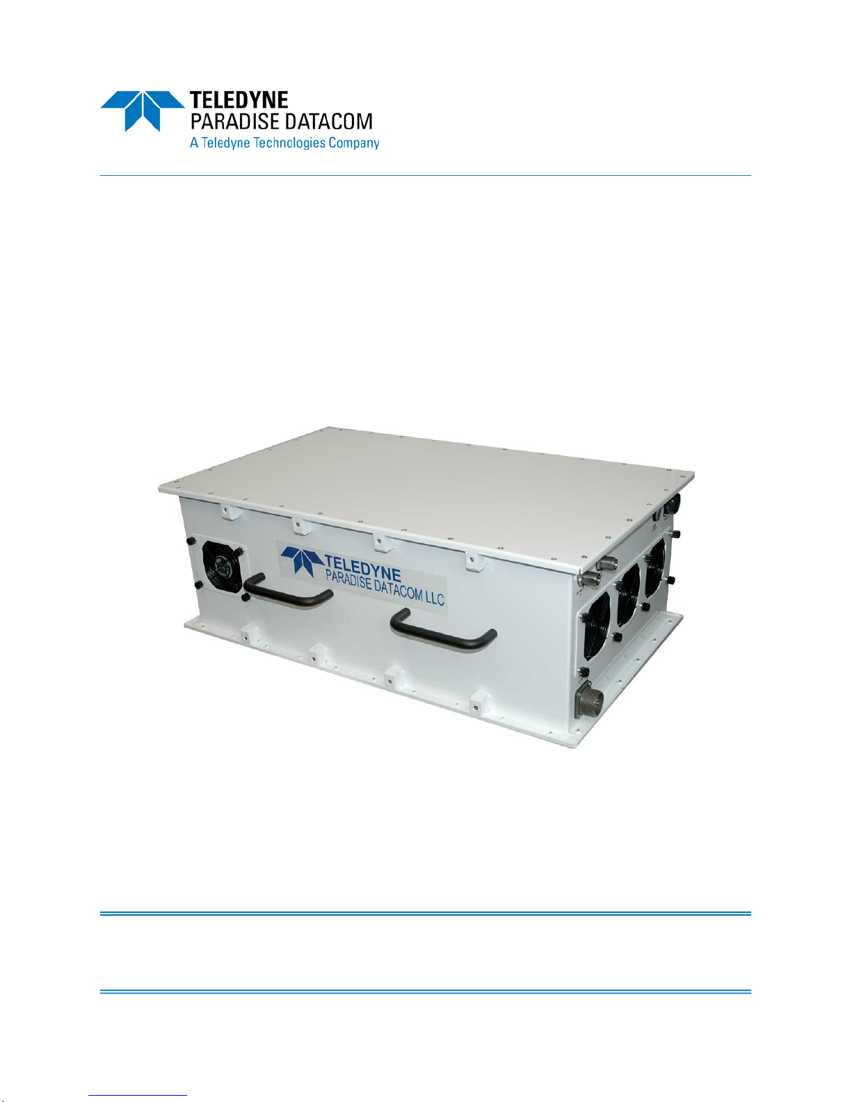
High Power Outdoor
Solid State Power Amplifier
Operations Manual
Teledyne Paradise Datacom LLC Phone: (814) 238-3450
328 Innovation Blvd., Suite 100 Fax: (814) 238-3829
State College, PA 16803 USA Web: www.paradisedata.com
Email: sales@paradisedata.com
211670 REV D ECO 18186 08/02/2016

Teledyne Paradise Datacom LLC, a Teledyne Telecommunications company, is a single source for high power
solid state amplifiers (SSPAs), Low Noise Amplifiers (LNAs), Block Up Converters (BUCs), and Modem
products. Operating out of two primary locations, Witham, United Kingdom, and State College, PA, USA,
Teledyne Paradise Datacom has a more than 20 year history of providing innovative solutions to enable satellite
uplinks, battlefield communications, and cellular backhaul.
Teledyne Paradise Datacom LLC Teledyne Paradise Datacom Ltd.
328 Innovation Blvd., Suite 100 2&3 The Matchyns, London Road, Rivenhall End
State College, PA 16803 USA Witham, Essex CM8 3HA England
(814) 238-3450 (switchboard) +44 (0) 1376 515636
(814) 238-3829 (fax) +44 (0) 1376 533764 (fax)
Information in this document is subject to change without notice. The latest revision of this document may be
downloaded from the company web site: http://www.paradisedata.com.
Use and Disclosure of Data
The information contained herein is classified as EAR99 under the U.S. Export Administration Regulations.
Export, re-export or diversion contrary to U.S. law is prohibited.
No part of this document may be reproduced or transmitted in any form without the written permission of
Teledyne Paradise Datacom LLC.
All rights are reserved in this document, which is property of Teledyne Paradise Datacom LLC. This document
contains proprietary information and is supplied on the express condition that it may not be disclosed,
reproduced or transmitted in any form without the written permission of Teledyne Paradise Datacom LLC.
All other company names and product names in this document are property of the respective companies.
© 2014-2016 Teledyne Paradise Datacom LLC
Printed in the USA
2 211670 REV D Operations Manual, High Power Outdoor SSPA

Table of Contents
Table of Contents .................................................................................................................. 3
List of Figures ........................................................................................................................ 7
List of Tables ......................................................................................................................... 8
Section 1: General Information ........................................................................................... 9
1.0 Introduction ........................................................................................................... 9
1.1 Description ............................................................................................................ 9
1.2 Specifications ........................................................................................................ 9
1.3 Equipment Supplied .............................................................................................. 9
1.4 Inspection .............................................................................................................. 9
1.5 Shipment ............................................................................................................. 10
1.6 Safety Considerations ......................................................................................... 10
1.6.1 High Voltage Hazards ........................................................................... 10
1.6.2 High Current Hazards ............................................................................ 10
1.6.3 RF Transmission Hazards ..................................................................... 11
1.6.4 Electrical Discharge Hazards ................................................................ 11
1.6.5 High Leakage Current ........................................................................... 11
Section 2: Description of Unit........................................................................................... 13
2.0 Introduction ......................................................................................................... 13
2.1 Description of Unit ............................................................................................... 13
2.2 Installation of Unit ............................................................................................... 14
2.3 Connectors .......................................................................................................... 15
2.3.1 RF Input Port (J1) [Type N (F)] .............................................................. 16
2.3.2 RF Output (J2) ...................................................................................... 16
2.3.3 RF Output Sample Port (J3) [Type N (F)] .............................................. 16
2.3.4 M&C Connector (J4) [MS3112E18-32S] ............................................... 16
2.3.5 Link Port (J5) [MS3112E10-6S] ............................................................. 18
2.3.6 Switch Port (J6) [MS3112E10-6S] ......................................................... 18
2.3.7 AC Input Connector (J7) [MS3102E20-19P] ......................................... 18
2.3.7.1 Power Cable Construction ....................................................... 18
2.3.8 AUX PWR Port (J8) [MS3112E10-6S] ................................................... 19
2.3.9 Handheld Connector (J10) [MS3112E12-8S] ........................................ 19
2.3.10 Chassis Ground Terminal .................................................................... 20
2.3.11 RF Input Sample Port (optional) [Type N (F)] ...................................... 20
2.4 Physical Features ............................................................................................... 20
2.4.1 Summary Alarm Indicator ...................................................................... 20
2.4.2 Airflow and Removable Fan Trays ........................................................ 20
2.4.3 Waveguide Pressure Window (option) .................................................. 20
Section 3: Quick Start and Operation .............................................................................. 21
3.0 Introduction ......................................................................................................... 21
3.1 Quick Start Cables .............................................................................................. 21
3.2 Quick Start Connections ..................................................................................... 22
3.2.1 Set PC Configuration ............................................................................. 22
Operations Manual, High Power Outdoor SSPA 211670 REV D 3

3.2.2 Quick Start Ethernet Connection ........................................................... 22
3.2.3 Quick Start RS-232 Connection ............................................................ 23
3.2.4 Setting Custom IP Address ................................................................... 24
3.3 Universal M&C Operation ................................................................................... 25
3.3.1 Universal M&C Status Window .............................................................. 26
3.3.1.1 Signal Indicators ...................................................................... 26
3.3.1.2 Fault Status Indicators ............................................................. 27
3.3.1.3 Voltage, Current and Temperature Display ............................. 28
3.3.1.4 Gain Adjustment ...................................................................... 28
3.3.1.5 Forward and Reflected RF Power Indicators ........................... 28
3.3.2 Universal M&C Settings Window ........................................................... 29
3.3.3 IP Setup Window ................................................................................... 31
3.3.4 Universal M&C Preferences .................................................................. 32
3.4 Web-based M&C ................................................................................................. 33
3.4.1 Navigating the Web M&C ...................................................................... 34
Section 4: L Band Operation ............................................................................................ 39
4.0 Block Up Converter Overview ............................................................................. 39
4.1 ZBUC Features ................................................................................................... 40
4.2 ZBUC Converter Theory of Operation ................................................................. 41
4.3 Smart Reference Technology ............................................................................. 41
4.4 ZBUC FSK Monitor and Control .......................................................................... 42
4.5 Typical System Configuration ............................................................................. 43
4.6 IFL Cable Considerations .................................................................................... 43
Section 5: Redundant System Operation ........................................................................ 45
5.0 Redundant System Concepts ............................................................................. 45
5.1 High Power Outdoor Amplifier in 1:1 Redundancy .............................................. 47
5.1.1 Hardware Setup .................................................................................... 48
5.1.2 Software Setup ...................................................................................... 49
5.1.2.1 Stand-Alone 1:1 Redundant System ........................................ 49
5.1.2.2 PC Control using RS232 and Paradise M&C Software ............ 52
5.1.2.3 PC Control using RS-485 and Paradise M&C Software .......... 57
5.2 High Power Outdoor SSPA in 1:2 Redundant Systems ...................................... 59
5.2.1 Hardware Setup .................................................................................... 60
5.2.2 Software Setup ...................................................................................... 60
5.2.2.1 PC Control using Universal M&C Software .............................. 61
Section 6: Phase Combined Systems .............................................................................. 65
6.0 Phase Combining Overview ................................................................................ 65
6.1 1:1 Fixed Phase Combined Systems .................................................................. 67
6.2 1:2 Fixed Phase Combined Systems .................................................................. 68
Section 7: Maintenance and Troubleshooting ................................................................ 69
7.0 Introduction ......................................................................................................... 69
7.1 Cooling System Maintenance ............................................................................. 69
7.2 Fan Removal and Heatsink Cleaning .................................................................. 69
7.2.1 Fan Replacement ............................................................................................ 70
7.3 Troubleshooting guide ......................................................................................... 72
4 211670 REV D Operations Manual, High Power Outdoor SSPA

7.3.1 Unit doesn’t power up ............................................................................ 72
7.3.2 Unit powers on, LED lamp blinks (red or green) .................................... 72
7.3.3 Unit powers on, LED lamp glows red .................................................... 72
7.3.4 SSPA unit powers up, LED lamp glows green, no RF present .............. 72
7.3.5 Cannot connect to SSPA through remote control interface ................... 73
7.3.6 The FSK link between a modem and the SSPB unit is not working ...... 73
Section 8: Remote Control Interface ................................................................................ 75
8.0 Serial Protocol Overview ..................................................................................... 75
8.1 Serial Communication ......................................................................................... 78
8.1.1 Header Packet ....................................................................................... 78
8.1.1.1 Frame Sync Word .................................................................... 78
8.1.1.2 Destination Address ................................................................ 78
8.1.1.3 Source Address ....................................................................... 79
8.1.2 Data Packet ........................................................................................... 79
8.1.2.1 Protocol ID ............................................................................... 79
8.1.2.2 Request ID ............................................................................... 79
8.1.2.3 Command ................................................................................ 79
8.1.2.4 Data Tag .................................................................................. 80
8.1.2.5 Data Address / Error Status / Local Port Frame Length .......... 81
8.1.2.6 Data Length ............................................................................. 81
8.1.2.7 Data Field ................................................................................ 81
8.1.3 Trailer Packet ........................................................................................ 82
8.1.3.1 Frame Check ........................................................................... 82
8.1.4 Timing issues ........................................................................................ 82
8.1.5 Serial Communications Protocol ........................................................... 83
8.2 Ethernet Interface ............................................................................................... 87
8.2.1 Overview ............................................................................................... 87
8.2.2 IPNet Interface ...................................................................................... 87
8.2.2.1 General Concept ..................................................................... 87
8.2.2.2 Setting IPNet Interface............................................................. 89
8.2.2.3 Troubleshooting IP Connectivity .............................................. 89
8.2.3 SNMP Interface ..................................................................................... 90
8.2.3.1 SNMP MIB Tree ...................................................................... 91
8.2.3.2 Description of MIB Entities ....................................................... 92
8.2.4 Extended SNMP .................................................................................... 93
8.2.4.1 Extended SNMP MIB Tree ...................................................... 94
8.2.4.2 Extended SNMP MIB Tree Elements in Detail ......................... 96
8.3 M&C via SNMP ................................................................................................. 100
8.3.1 Connecting to a MIB Browser .............................................................. 101
8.3.2 SNMP V3 implementation issues in SSPAs ........................................ 102
Section 9: Option, Universal Handheld Controller ........................................................ 105
9.0 Overview, RCH-1000 ........................................................................................ 105
Appendix A: Installation, Uni-Strut Frame for 1:1 Redundant System Mounting ...... 107
Appendix B: Installation, Uni-Strut Frame for 1:2 Phase Combined System ............. 117
Documentation................................................................................................................. 133
Operations Manual, High Power Outdoor SSPA 211670 REV D 5

List of Figures
Figure 2-1: Outline Drawing, Ku-Band H-Series High Power Outdoor SSPA ........... 13
Figure 2-2: Connectors at Bottom of Enclosure ........................................................ 14
Figure 2-3: RF Output Connector at Top of Enclosure .............................................. 15
Figure 3-1: Ethernet Quick Start Cable, 207755 ....................................................... 21
Figure 3-2: RS-232 Quick Start Cable, 207998 ......................................................... 21
Figure 3-3: Universal M&C Add Unit menu ............................................................... 25
Figure 3-4: Add Compact Outdoor SSPA window, via Serial (left) or Internet (right) 25
Figure 3-5: Universal M&C Status Window ............................................................... 26
Figure 3-6: Fault Indicators ....................................................................................... 27
Figure 3-7: Universal M&C Settings Window ............................................................ 29
Figure 3-8: Spare Fault Wizard ................................................................................. 30
Figure 3-9: Universal M&C IP Setup Window ........................................................... 31
Figure 3-10: Preferences Window ............................................................................. 32
Figure 3-11: Example, Log Entry .............................................................................. 32
Figure 3-12: Enter IP Address for Amplifier (Default is 192.168.0.9) ........................ 33
Figure 3-13: M&C Applet Loading into Browser Window .......................................... 33
Figure 3-14: Enter Password (Default is “paradise”) ................................................. 34
Figure 3-15: Status and Faults Window Descriptions ............................................... 34
Figure 3-16: Communication Settings Window Descriptions .................................... 35
Figure 3-17: General Settings Window Descriptions ................................................. 36
Figure 3-18: Fault Settings Window Descriptions ..................................................... 37
Figure 4-1: Configuration Matrix, High Power Outdoor SSPA, BUC Options ............ 39
Figure 4-2: High Power Outdoor Block Diagram of BUC / SSPA System ................. 40
Figure 4-3: High Power Outdoor SSPB with Q-Series Q-Flex Modem ...................... 43
Figure 5-1: Standard 1:1 Redundant System with input/output switches .................. 45
Figure 5-2: 1:1 Redundant System with input splitter substituted for input switch ..... 45
Figure 5-3: 1:1 Redundant System with L Band input ............................................... 46
Figure 5-4: Outline Drawing, 1:1 Redundant High Power Outdoor System .............. 47
Figure 5-5: Schematic, 1:1 Redundant High Power Outdoor System ....................... 48
Figure 5-6: 1:1 System with RS-232 Communication to each Amplifier .................... 49
Figure 5-7: M&C Program “SSPA Settings” window ................................................. 50
Figure 5-8: Adding a SSPA Monitor and Control Window ......................................... 52
Figure 5-9: Add New Compact Outdoor SSPA window ............................................ 53
Figure 5-10: Individual SSPA Operation Window ...................................................... 53
Figure 5-11: Universal M&C, Add Unit Menu Tree .................................................... 54
Figure 5-12: Universal M&C, Add 1:1 Redundant System Window .......................... 54
Figure 5-13: Universal M&C, showing a configured 1:1 Redundant System ............. 55
Figure 5-14: Dialog window, Affirm mute of on-line amplifier .................................... 55
Figure 5-15: Control Panel showing Unit 1 faulted and signal routed to Unit 2 ......... 56
Figure 5-16: Unit1 Status panel showing Summary and Temperature Faults ........... 56
Figure 5-17: 1:1 Redundant System with RS-485 Full Duplex Communication ........ 57
Figure 5-18: 1:1 Redundant System with Half Duplex Communication ..................... 58
Figure 5-19: Block Diagram, 1:2 Redundant System ................................................ 59
Figure 5-20: Universal M&C Application, Add Unit Screen ....................................... 61
Figure 5-21: Universal M&C Application, Add High Power Outdoor SSPA ............... 61
Figure 5-22: Universal M&C, High Power Outdoor SSPA Status Window ................ 62
Figure 5-23: Universal M&C Application, Add Controller .......................................... 62
Figure 5-24: Universal M&C Application, Controller Status Window ......................... 63
6 211670 REV D Operations Manual, High Power Outdoor SSPA

Figure 6-1: Phase Combined Amplifier System ......................................................... 65
Figure 6-2: 1:1 Fixed Phase Combined System with FPRC-1100 controller ............. 66
Figure 6-3: FPRC-1100 Phase Combined System Controller .................................... 67
Figure 6-4: Block Diagram, 1:2 Fixed Phase Combined System ............................... 68
Figure 8-1: Amplifier Remote Control Interface Stack ................................................ 75
Figure 8-2: Basic Communication Packet .................................................................. 78
Figure 8-3: Header Sub-Packet ................................................................................. 78
Figure 8-4: Data Sub-Packet ..................................................................................... 79
Figure 8-6: UDP Redirect Frame Example ................................................................ 88
Figure 8-7: Universal M&C, IP Setup tab ................................................................. 100
Figure 8-8: Universal M&C, Settings tab .................................................................. 100
Figure 8-9: GetIF Application Parameters Tab ........................................................ 101
Figure 8-10: Getif MBrowser window, with update data in output data box ............. 101
Figure 9-1: Universal Handheld Controller (RCH-1000) .......................................... 105
Figure 9-2: Communication Cable (L212640-2) for High Power Outdoor SSPAs .... 105
Figure A-1: Uni-Strut Assembly ............................................................................... 109
Figure A-2: Uni-Strut Assembly, Hardware Placement ............................................ 110
Figure A-3: Uni-Strut Assembly, Base Strut ............................................................. 110
Figure A-4: Mount HPAs to Frame ........................................................................... 111
Figure A-5: Components, Waveguide Switch Array ................................................. 112
Figure A-6: Mounting Switch Support to Frame ....................................................... 112
Figure A-7: Connect Waveguide to Switch, Ku-Band (typical) ................................. 113
Figure A-8: Switch Assembly Installation, Ku-Band (typical) ................................... 113
Figure A-9: Waveguide Installation, Ku-Band (typical) ............................................. 114
Figure A-10: Input Plate Assembly (with splitter) ..................................................... 115
Figure A-11: Mount Input Plate Assembly to Frame ................................................ 115
Figure A-12: Connect Switch and Link Cables ........................................................ 116
Figure B-1: Uni-Strut Assembly ............................................................................... 119
Figure B-2: Uni-Strut Assembly, Hardware Placement ............................................ 120
Figure B-3: Uni-Strut Assembly, Attach Footers ...................................................... 120
Figure B-4: Install Amplifiers .................................................................................... 121
Figure B-5: Install Signal Box .................................................................................. 122
Figure B-6: Components, Output Waveguide and Switch Array .............................. 123
Figure B-7: Attach W/G Segment 214784-1 to SW2 ................................................ 124
Figure B-8: Attach W/G Segment 214787-1, SW1 and W/G Segment 214783-1 .... 124
Figure B-9: Attach W/G Segment 214785-1, Magic Tee and W/G 214786-1 .......... 125
Figure B-10: Attach W/G Assembly to Signal Box Support Brackets ....................... 125
Figure B-11: Attach Magic Tee Support Bracket to Uni-Strut Frame ....................... 126
Figure B-12: Attach W/G Segment 214782-1 to SW1 .............................................. 126
Figure B-13: Insert O-Ring Gasket at HPA RF Output and Secure Waveguide ...... 127
Figure B-14: Semi-Rigid Coaxial Cables ................................................................. 128
Figure B-15: Connect W5 to SW2 (shown from top of switch) ................................. 129
Figure B-16: Connect W4 to Port J8 ........................................................................ 129
Figure B-17: Connect W4 to Diode/Attenuator at Crossguide Coupler .................... 129
Figure B-18: Connect W1 to Signal Box Port J4 (HPA1) and SW2-2 ...................... 130
Figure B-19: Connect W2 to Signal Box Port J2 (HPA2) ......................................... 130
Figure B-20: Connect W3 to Signal Box Port J3 (HPA3) ......................................... 130
Figure B-21: System Control Cable ......................................................................... 131
Figure B-22: Schematic, Connections for 1:1 BUC and 1:2 HPA System Cables ... 132
Operations Manual, High Power Outdoor SSPA 211670 REV D 7

List of Tables
Table 2-1: Monitor & Control Connector (J4) Pin-Outs ............................................. 16
Table 2-2: Link Port (J5) Pin-Outs ............................................................................. 17
Table 2-3 Switch Port (J6) Pin-Outs .......................................................................... 17
Table 2-4: AC Input Connector (J7) Pin-Outs ........................................................... 17
Table 2-5: AUX PWR Port (J8) Pin-Outs................................................................... 18
Table 2-6: Handheld Connector (J10) Pin-Outs ........................................................ 18
Table 4-1: ZBUC Converter Frequency Specifications ............................................. 40
Table 4-2: ZBUC RF Output Phase Noise Specification ........................................... 41
Table 4-3: Common Coaxial Cable Characteristics .................................................. 43
Table 8-1: Interface Selection ................................................................................... 76
Table 8-2: Unique Network Address Hardware Select .............................................. 76
Table 8-3: Command Byte Values ............................................................................ 80
Table 8-4: Data Tag Byte Values .............................................................................. 80
Table 8-5: Error Status Bytes .................................................................................... 81
Table 8-6: Request Frame Structure ......................................................................... 83
Table 8-7: Response Frame Structure ...................................................................... 83
Table 8-8: System Settings Data Values .................................................................. 84
Table 8-9: System Threshold Data Values ................................................................ 85
Table 8-10: System Condition Addressing ................................................................ 86
Table 8-11: OSI Model for SSPA Ethernet IP Interface ............................................ 88
Table 8-12: Detailed Settings for CO SSPA mode (Device Type=2) ........................ 97
Table 8-13: Detailed Thresholds ............................................................................... 98
Table 8-14: Detailed Conditions ................................................................................ 99
Table A-1: Parts List, Mounting Kit Assembly (L213302-1) ..................................... 108
Table B-1: Parts List, Mounting Kit Assembly (L214792-1) ..................................... 118
8 211670 REV D Operations Manual, High Power Outdoor SSPA

Section 1: General Information
1.0 Introduction
This section provides the general information for the Teledyne Paradise Datacom High Power
Outdoor (H-Series) Solid State Power Amplifier (SSPA). This includes a description of the unit
and safety precautions.
1.1 Description
The H-Series high power outdoor SSPA contains an internal microprocessor which allows full
monitoring and control via a remote serial (RS-232 or RS-485) and Ethernet connector. The
microprocessor monitors various voltages, currents and temperatures within the unit for a full
fault analysis. The user also has the ability to select additional faults related to the RF
output level, an optional reflected RF power level and operating temperature.
An internal attenuator allows up to 20.0 dB of attenuation to be applied to the RF signal.
Temperature compensation limits the amplifier’s output response from varying significantly
over the operating temperature. Also, the system contains an output sample port.
1.2 Specifications
Refer to the specification sheet in Appendix C for complete specifications.
1.3 Equipment Supplied
The following equipment is supplied with each unit:
• High Power Outdoor SSPA
• Quick Start Cable
• Operations Manual High Power Outdoor SSPA [211670]
1.4 Inspection
When the unit is received, an initial inspection should be completed. First ensure that the
shipping container is not damaged. If it is, have a representative from the shipping company
present when the container is opened. Perform a visual inspection of the equipment to make
sure that all items on the packing list are enclosed. If any damage has occurred or if items are
missing, contact:
Teledyne Paradise Datacom LLC
328 Innovation Blvd., Suite 100
State College, PA 16803 USA
Phone: +1 (814) 238-3450
Fax: +1 (814) 238-3829
Operations Manual, High Power Outdoor SSPA 211670 REV D 9

1.5 Shipment
To protect the High Power Outdoor SSPA during shipment, use high quality commercial
packing methods. When possible, use the original shipping container and its materials. Reliable commercial packing and shipping companies have facilities and materials to adequately
repack the instrument.
1.6 Safety Considerations
Potential safety hazards exist unless proper precautions are observed when working with this
unit. To ensure safe operation, the user must follow the information, cautions and warnings
provided in this manual as well as the warning labels placed on the unit itself.
1.6.1 High Voltage Hazards
High Voltage, for the purpose of this section, is any voltage in excess of 30V. Voltages above
this value can be hazardous and even lethal under certain circumstances. Care should be
taken when working with devices that operate at high voltage.
• All probes and tools that contact the equipment should be properly insulated to prevent the operator from coming in contact with the voltage.
• The work area should be secure and free from nonessential items.
• Operators should never work alone on high voltage devices. There should always
be another person present in the same work area to assist in the event of an emergency.
• Operators should be familiar with procedures to employ in the event of an emergency, i.e., remove all power, CPR, etc.
• An AC powered unit will have 230 VAC entering through the AC power connector.
Caution is required when working near this connector, the AC circuit breaker, or the
internal power supply.
1.6.2 High Current Hazards
Many high power devices are capable of producing large surges of current. This is true at all
voltages, but needs to be emphasized for low voltage devices. Low voltage devices provide
security from high voltage hazards, but also require higher current to provide the same power. High current can cause severe injury from burns and explosion. The following precautions
should be taken on devices capable of discharging high current:
• Remove all conductive personal items (rings, watches, medals, etc.)
• The work area should be secure and free of non-essential items.
• Wear safety glasses and protective clothing.
• Operators should never work alone on high risk devices. There should always be
another person present in the same area to assist in the event of an emergency.
• Operators should be familiar with procedures to employ in the event of an emergency, i.e., remove all power, CPR, etc.
10 211670 REV D Operations Manual, High Power Outdoor SSPA

Large DC currents are generated to operate the RF Module inside of the enclosure. EXTREME CAUTION IS REQUIRED WHEN THE ENCLOSURE IS OPEN AND THE AMPLIFIER IS OPERATING. DO NOT TOUCH ANY OF THE CONNECTIONS ON THE RF MODULES WHEN THE AMPLIFIER IS OPERATING. CURRENTS IN EXCESS OF 60 AMPERES
MAY EXIST ON ANY ONE CONNECTOR.
1.6.3 RF Transmission Hazards
RF transmissions at high power levels may cause eyesight damage and skin burns. Prolonged exposure to high levels of RF energy has been linked to a variety of health issues.
Please use the following precautions with high levels of RF power.
• Always terminate the RF input and output connector prior to applying prime AC input power.
• Never look directly into the RF output waveguide
• Maintain a suitable distance from the source of the transmission such that the pow-
er density is below recommended guidelines in ANSI/IEEE C95.1. The power density specified in ANSI/IEEE C95.1-1992 is 10 mW/cm2. These requirements adhere to OSHA Standard 1910.97.
• When a safe distance is not practical, RF shielding should be used to achieve the
recommended power density levels.
1.6.4 Electrical Discharge Hazards
An electric spark can not only create ESD reliability problems, it can also cause serious safety hazards. The following precautions should be followed when there is a risk of electrical discharge:
• Follow all ESD guidelines
• Remove all flammable material and solvents from the area.
• All probes and tools that contact the equipment should be properly insulated to pre-
vent electrical discharge.
• The work area should be secure and free from non-essential items.
• Operators should never work alone on hazardous equipment. There should always
be another person present in the same work area to assist in the event of an emergency.
Operators should be familiar with procedures to employ in the event of an emergency, i.e.,
remove all power, CPR, etc.
1.6.5 High Leakage Current
The equipment may have more than 3.5 mA
leakage current. Make sure a connection to earth
ground is present before applying prime power,
and after removing prime power.
Operations Manual, High Power Outdoor SSPA 211670 REV D 11

THIS PAGE LEFT INTENTIONALLY BLANK
12 211670 REV D Operations Manual, High Power Outdoor SSPA
Section 2: Description of Unit
2.0 Introduction
This section contains operating information including a description of the Teledyne Paradise
Datacom H-Series High Power Outdoor SSPA, its connectors and their functions.
2.1 Description of Unit
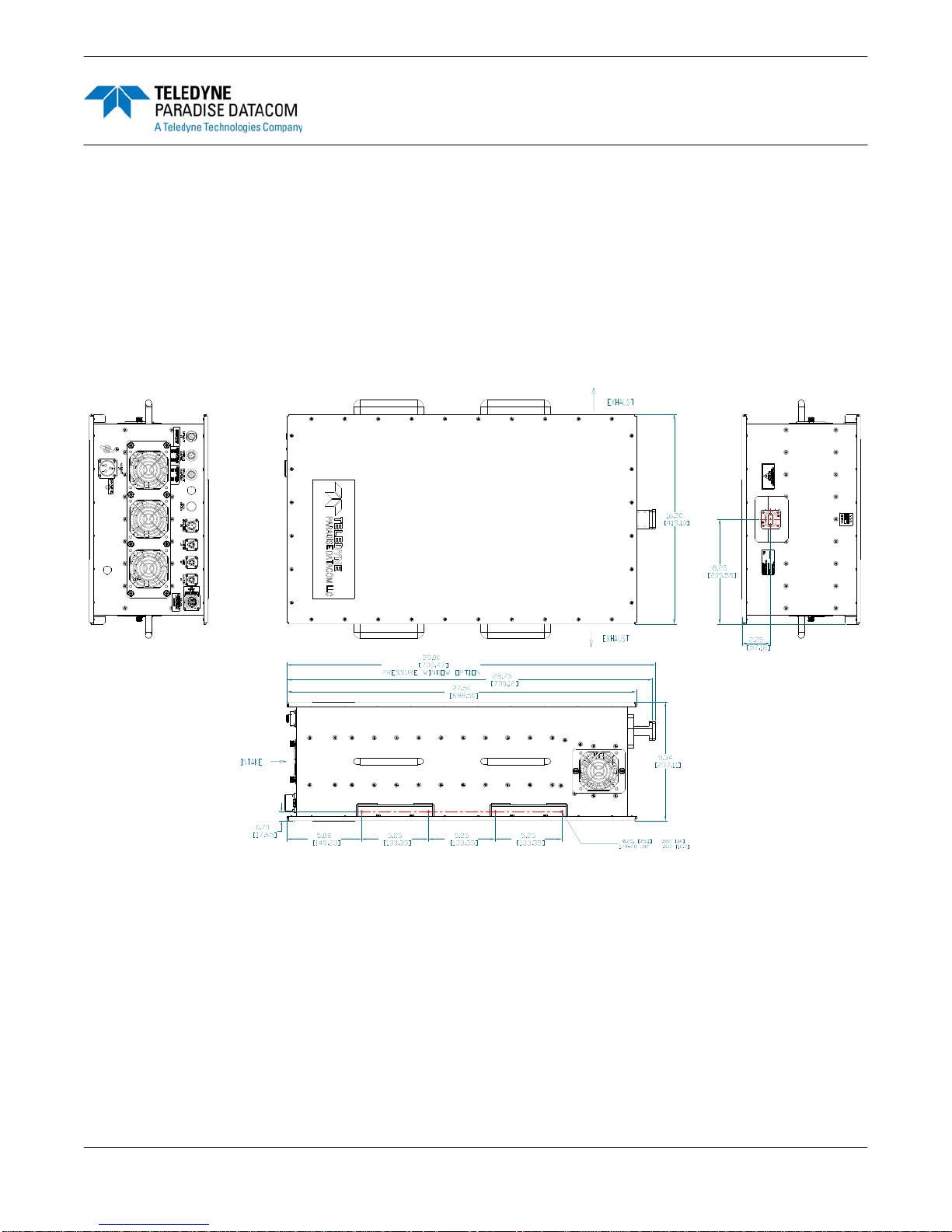
Figure 2-1 shows an outline drawing of a typical H-Series High Power Outdoor SSPA. The
unit enclosure has overall dimensions of 27.5 inches (698.5 mm) by 16.5 inches (419.1 mm)
by 9.335 inches (237.1 mm).
Figure 2-1: Outline Drawing, Ku-Band H-Series High Power Outdoor SSPA
The enclosure is sealed to prevent water and debris intrusion, and has an ingress protection
rating of IP54. A series of fans provides circulation of ambient air through the enclosure to
cool the internal RF module.
A status indicator is located above the intake fan panel. When the unit is operating normally,
the status indicator illuminates green. If the unit enters a fault condition, the status indicator
illuminates red. Fault conditions may be monitored remotely through the Monitor & Control
connector (Port J4).
Operations Manual, High Power Outdoor SSPA 211670 REV D 13
x
x

2.2 Installation of Unit
When installing the H-Series High Power Outdoor SSPA, consider the following:
• There should be at least 8” clearance between the intake fans and any surface,
and 8” clearance from the SSPA’s exhaust fans.
• The SSPA should never be enclosed in such a manner that restricts airflow.
• Regular inspection and cleaning of the fans and heatsink is required.
• Normal operating range of the SSPA is -40 to +60 °C.
• The unit will start up in a muted state. To unmute the amplifier, pins V and B of Port
J4 need to be shorted.
A series of mounting holes are located along the sides of the unit that include the lifting handles, and on the sides of the unit that include the intake and exhaust fans. If utilizing the
mounting holes on the sides that include the fans, ensure the mounting brackets do not interfere with the air circulation into and out of the unit.
Warning! The SSPA should never be mounted in such a way that the in-
take fans face up. Doing so will void the warranty.
The H-Series High Power Outdoor SSPA weighs between 100 and 140 lbs. (45.5 - 63.6 kg),
depending on the power level of the unit. If mounting the unit to a boom or king post, ensure
the mounting brackets and surface are capable of supporting the weight of the unit. At least
two persons are required to lift the unit into position for mounting purposes.
See Appendix A for instructions on assembling a mounting frame for a redundant system
installation.
14 211670 REV D Operations Manual, High Power Outdoor SSPA
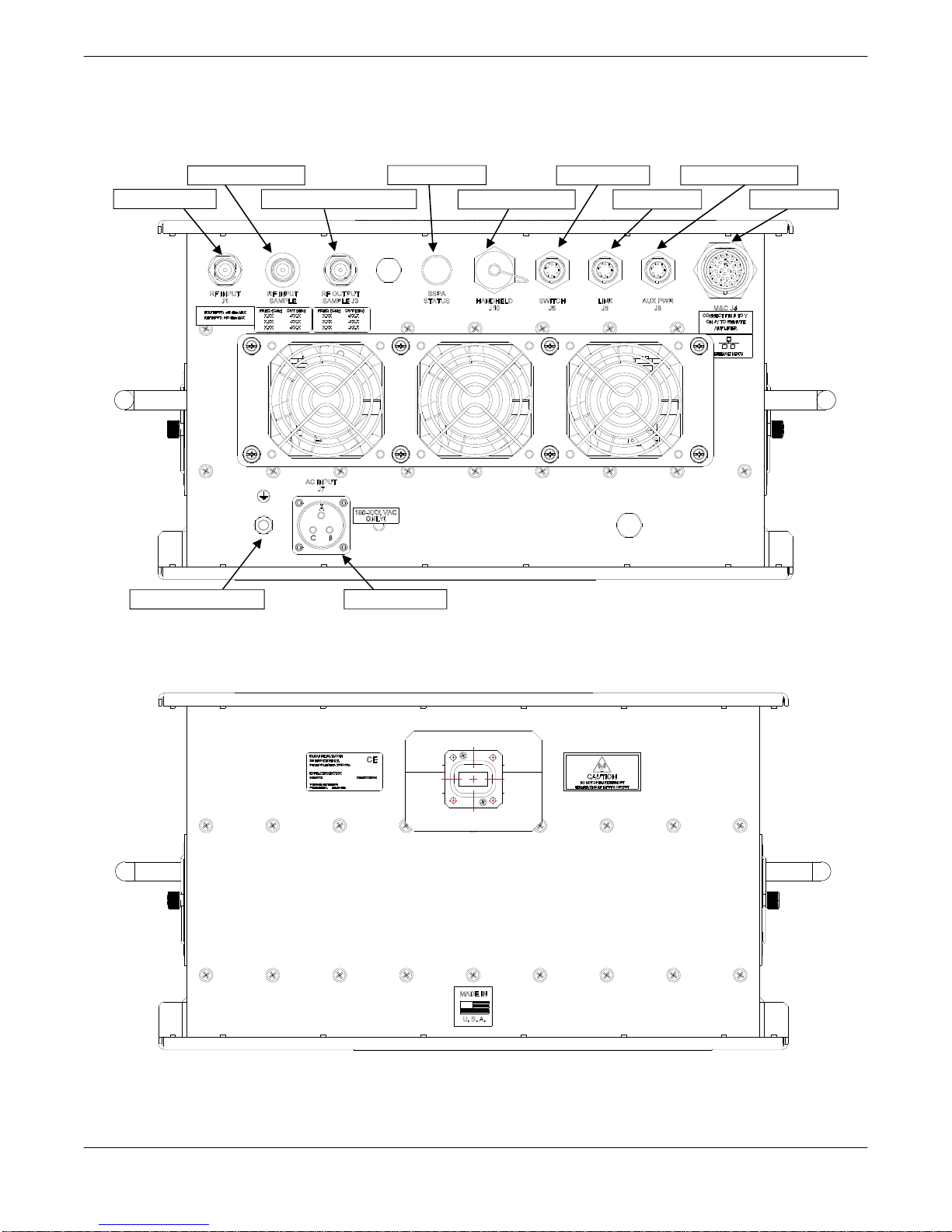
2.3 Connectors
Figure 2-2 and Figure 2-3 show the connectors available on the unit.
RF INPUT SAMPLE
RF INPUT (J1)
GROUND TERMINAL
SSPA STATUS
RF OUTPUT SAMPLE (J3)
AC INPUT (J7)
HANDHELD (J10)
SWITCH (J6)
LINK (J5)
AUX PWR (J8)
M&C (J4)
Figure 2-2: Connectors at Bottom of Enclosure
Figure 2-3: RF Output Connector at Top of Enclosure
Operations Manual, High Power Outdoor SSPA 211670 REV D 15

2.3.1 RF Input Port (J1) [Type N (F)]
The Type N (F) connector shown at the top left of Figure 2-2 is the RF Input connector.
Warning! Maximum RF input that should be introduced at this connector
is +15 dBm.
An optional L-Band input is available for units with an internal block up converter.
2.3.2 RF Output (J2)
The RF Output shown in Figure 2-3 is a WR-75 waveguide flange with 0.206” diameter
through holes, used with Ku-Band amplifiers. C-Band amplifiers utilize a CPRG-137 waveguide flange with 0.206” diameter through holes. X-Band SSPAs use CPRG-112 waveguide
flanges with 0.206” diameter through holes. S-Band amplifiers have Type N (F) connectors.
Warning! RF Hazards apply when power is applied to the unit. Do not
operate the unit without having a termination or mating connection on
the RF Output Port. Do not look directly into the RF Output waveguide.
2.3.3 RF Output Sample Port (J3) [Type N (F)]
The Type N (F) connector at port J3 is the RF Output Sample port, and provides a coupled
sample of the RF output signal. A calibration label is affixed next to this connector.
2.3.4 M&C Connector (J4) [MS3112E18-32S]
The Monitor and Control connector at Port J4 is a 32-pin MS-type circular connector. The pin-
outs for this connector are shown in Table 2-1.
The M&C connector contains a series of contact closures for monitoring amplifier faults as
well as TVS protected inputs for controlling some amplifier functions. Inputs react on the
closure to ground. Minimum closure time is 50mS. It requires a mating connector,
MS3116F18-32P, which is supplied with the unit.
Note: The RF output of the internal amplifier module is disabled until the Mute
Input (J4 – Pin B) is pulled to Ground (J4 – Pin V).
16 211670 REV D Operations Manual, High Power Outdoor SSPA
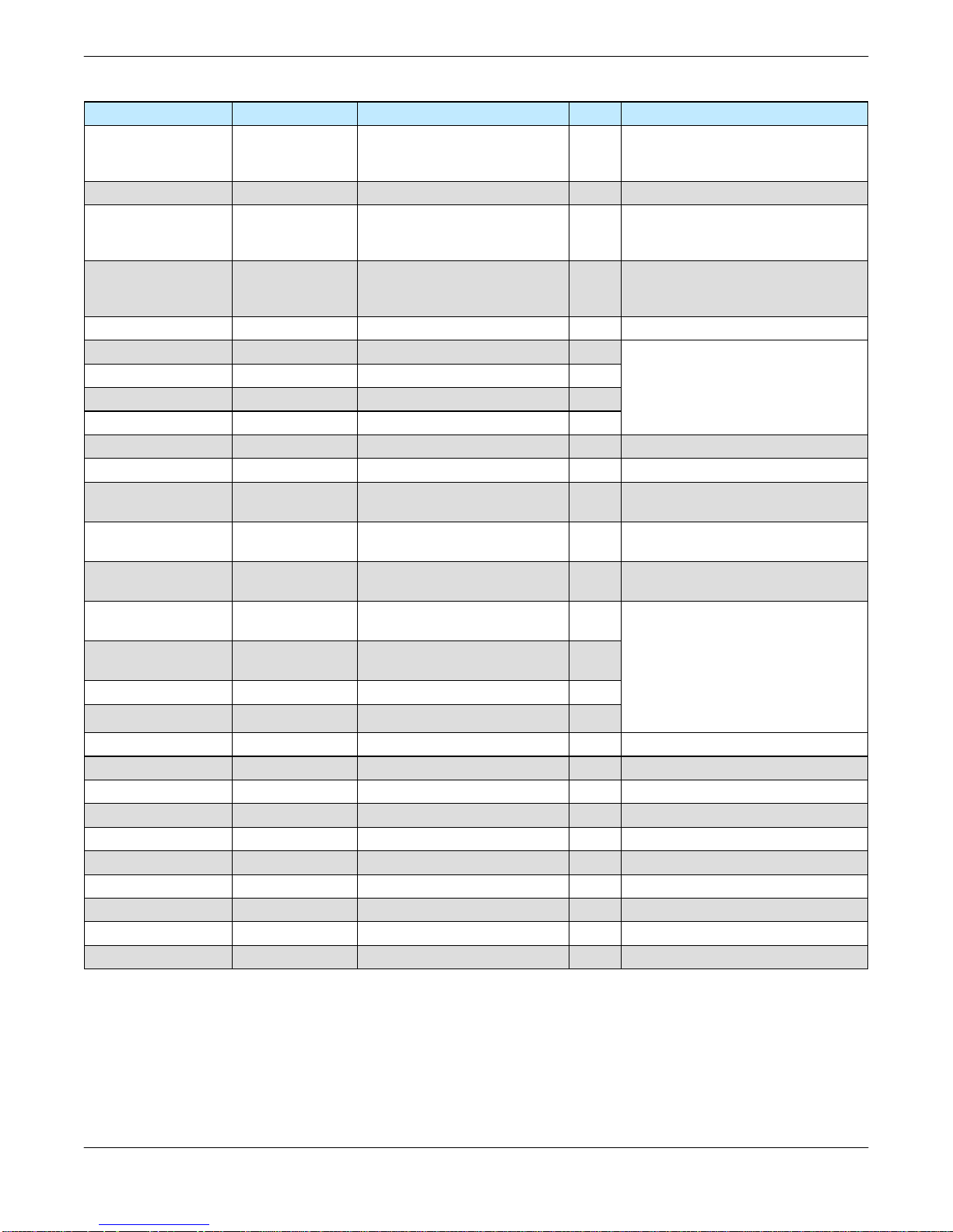
Table 2-1: Monitor & Control Connector (J4) Pin-Outs
Signal Type Function Pin Notes
Unit powers up muted;
Mute Input Closure to Ground Disables DC Power to SSPA B
Auxiliary Input Closure to Ground Auxiliary Input P
Closed on Fault
Summary Alarm Form C Relay
Auxiliary Alarm Form C Relay
Low RF Fault Output Open Collector High on Fault G Requires external pull-up
10 Base-T TX- W
10 Base-T RX- H
10 Base-T RX+ J
10 Base-T TX+ X
SSPA Spare Input Analog Input S +5V max.
Fan Fault Analog Output R
Gain Adjust Input Analog Input
Block Up Converter
Alarm
RS232 / RS485
Select
RS 485 TX-
or RS232 OUT
RS 485 RX-
or RS232 IN
RS 485 TX+ Serial TX Output Serial Link Data Port T
RS 485 RX+ Serial RX Input Serial Link Data Port U
GND Signal Ground Common Signal Return V Chassis ground
GND Signal Ground Isolated Comm Ground d Ground for Signals D, E, & F
Baud Select 0 Closure to Gnd Select Baud Rate & Protocol j
Baud Select 1 Closure to Gnd Select Baud Rate & Protocol e
PGM Switch Flash Firmware Port g Reserved for Programming
PGM CLK Flash Firmware Port c Reserved for Programming
PGM-Sout Flash Firmware Port K Reserved for Programming
PGM-Sin Flash Firmware Port Y Reserved for Programming
PGM +5V Flash Firmware Port h Reserved for Programming
PGM Enable Flash Firmware Port C Reserved for Programming
Open Collector High on Fault f Requires external pull-up
Closure to Ground Selects Serial Communication D
Serial TX Output Serial Link Data Port E
Serial RX Input Serial Link Data Port F
Common
Open on Fault
Closed on Fault
Common
Open on Fault
Adjusts Amplifier Gain
over 20 dB range
L
a
b
N
Z
M
A
This line must be pulled to ground
(V) to enable amplifier
L-a : normally open
a-b : normally closed
N-Z : normally open
Z-M: normally closed
See Section 8
2.5 vdc = Max Gain 75 dB
0.5 vdc = Min Gain 55 dB
Default is RS 485; pull to ground (d)
to enable RS 232
See Section 8
Refer to Table 8-1
Refer to Table 8-1
Operations Manual, High Power Outdoor SSPA 211670 REV D 17
2.3.5 Link Port (J5) [MS3112E10-6S]
The interface connector is used to connect two amplifiers when used in a 1:1 redundant
system. It is a 6 pin circular connector, MS3112E10-6S. It requires a mating connector,
MS3116F10-6P. A link cable is provided with a 1:1 Redundancy Kit, which can be purchased
separately. See Table 2-2.
Table 2-2: Link Port (J5) Pin-Outs
Pin # on J5 Connection Pin # on J5 Connection
A LINK OUT D N/C
B LINK IN E N/C
C N/C F GND
2.3.6 Switch Port (J6) [MS3112E10-6S]
When used in a 1:1 redundant system, the waveguide switch must be connected to the
switch port of each amplifier (MS3112E10-6S). See Table 2-3. It mates with MS3116F10-6P.
Table 2-3 Switch Port (J6) Pin-Outs
Pin # on J6 Connection Pin # on J6 Connection
A N/C D N/C
B N/C E POS 2
C +28 VDC F POS 1
2.3.7 AC Input Connector (J7) [MS3102E20-19P]
The prime power connector at Port J7 is a 3-pin MS-type connector, and provides universal
AC input by using auto-sensing power supplies. The AC input can operate over a range of
180-265 VAC, at 47 to 63 Hz. See the product datasheet for power requirements for your
model. The power supply is also power factor corrected, enabling the unit to achieve a power
factor greater than 0.9. The pin-outs for this connector are shown in Table 2-4.
Table 2-4: AC Input Connector (J7) Pin-Outs
Pin # on J7 Connection
A L1
B GND
C L2/N
Warning! Always terminate the RF input and output connectors prior to
applying prime AC input power!
Leakage current may exceed 3.5 mA. A connection to earth ground must be made prior to
connecting AC mains. Likewise, when removing AC mains, keep earth ground connected.
For the connection to earth ground, use a 12 AWG cable, UL rated for outdoor use. Connect
to the chassis ground stud using the supplied hardware. Tighten all hardware securely with a
wrench.
18 211670 REV D Operations Manual, High Power Outdoor SSPA
2.3.7.1 Power Cable Construction
Construct a power cable using the supplied MS3106F20-19S mating connector for J7. Use a
three-conductor, 25A, 12 AWG cable, UL rated for outdoor use. When constructing the cable,
discard the connector grommet, but keep the plastic ferrule. Connect the black conductor to
terminal A (L1) of the connector, the white conductor to terminal C (L2/N) of the connector,
and the green (protective earth ground) connector to terminal B (GND) of the connector.
Tighten the metal end-bell and fill with potting compound.
Warning! The protective earth pin B must be connected to AC mains earth
for both safety and EMC regulation compliance.
Note: For safety purposes, an isolation switch may be included in the power
cable to serve as a disconnect device in the event of an emergency or for unit
servicing. The amplifier itself has no on/off switch. When AC power is applied to
the unit, the unit’s power supplies and microcontroller are enabled. The internal
amplifier module is disabled until the Mute Line Input (J4, Pin B) is pulled to
Ground (J4, Pin V). See Section 2.3.4.
2.3.8 AUX PWR Port (J8) [MS3112E10-6S]
The 6-socket MS-type female connector at this port is capable of supplying auxiliary power.
This port is intended for use with factory-configured systems. Consult with the factory prior to
making any connection to this port. Table 2-5 shows the pin outs for the AUX PWR Port (J8).
Table 2-5: AUX PWR Port (J8) Pin-Outs
Pin # on J8 Connection Pin # on J8 Connection
A EXTERNAL FAULT IN D GND
B FAULT PULLUP E +15V EXTERNAL
C +15V LNA F GND
2.3.9 Handheld Connector (J10) [MS3112E12-8S]
This port is used to connect to a RCH-1000 Universal Handheld Controller. The controller is
shipped with a Communication Cable (L212640-2) which connects between the J10 connect-
or of the amplifier and the eight-pin UltraLock connector of the RCH-1000. Table 2-6 shows
the connector pin-outs for the Handheld Connector (J10). See drawing number 211668 for
operation instructions for the RCH-1000 Universal Handheld Controller.
Table 2-6: Handheld Connector (J10) Pin-Outs
Pin # on J8 Connection Pin # on J8 Connection
A RS-485 - E ENABLE
B RS-485 + F GND
C +15 VDC G N/C
D N/C H N/C
Operations Manual, High Power Outdoor SSPA 211670 REV D 19

2.3.10 Chassis Ground Terminal
A chassis ground terminal is provided on the intake fan side of the amplifier. A 1/4-20 threaded terminal is provided for equipment grounding.
2.3.11 RF Input Sample Port (optional) [Type N (F)]
This is a Type N (F) connector which provides a coupled sample of the RF Input. A calibration label is affixed to the enclosure next to this connector.
2.4 Physical Features
In addition to the I/O connectors, the H-Series High Power Outdoor SSPA features include a
summary alarm indicator and removable fan trays.
2.4.1 Summary Alarm Indicator
A summary alarm indicator LED is located on the input side of the amplifier. When the SSPA
is operating, this indicator illuminates GREEN. When in a fault condition, it illuminates RED.
When an external mute signal is detected, the indicator will blink GREEN if operating, or RED
if the amplifier is in a fault condition.
2.4.2 Airflow and Removable Fan Trays
The H-Series High Power Outdoor amplifier’s cooling system represents a landmark in microwave telecommunication amplifiers. It features a unique system of heatsinks that have been
computer optimized to provide extremely efficient cooling of all of the system’s functional
blocks. The cooling system is based on a forced convection technique in which a series of
fans provide the air intake and exhaust.
A minimum clearance of 8 inches (203 mm) should be maintained between each fan tray and
any mounting surface. This will ensure that there is no forced re-circulation of airflow from
exhaust to intake.
The fans should be examined periodically and any obstruction or debris should be cleared.
Inadequate air flow can cause the amplifier to overheat and cause a temperature fault. See
Section 7 for instructions on how to clean the fan trays and heatsink. In system configura-
tions, ensure that each unit in the system has sufficient ambient airflow, and adequate space
to maintain the fans for each unit.
Spare fan assemblies are available from Teledyne Paradise Datacom. The intake fan assembly is part number L213271-1. The exhaust fan assembly is part number L213272-1, and
there are two of these per amplifier.
2.4.3 Waveguide Pressure Window (option)
Ku-Band units may be ordered with an optional waveguide pressure window at the RF Output
(J2). This option is necessary for installations where the amplifier is connected to a pressurized transmission line (up to 15 PSI). All systems include a pressure window.
20 211670 REV D Operations Manual, High Power Outdoor SSPA
Section 3: Quick Start and Operation
3.0 Introduction
The H-Series High Power Outdoor SSPA is available with a standard Ethernet & RS-232/RS485 interface. This section summarizes the connections to a remote computer for various re-
mote communications. Table 2-1 summarizes the hardware connections of Port J4.
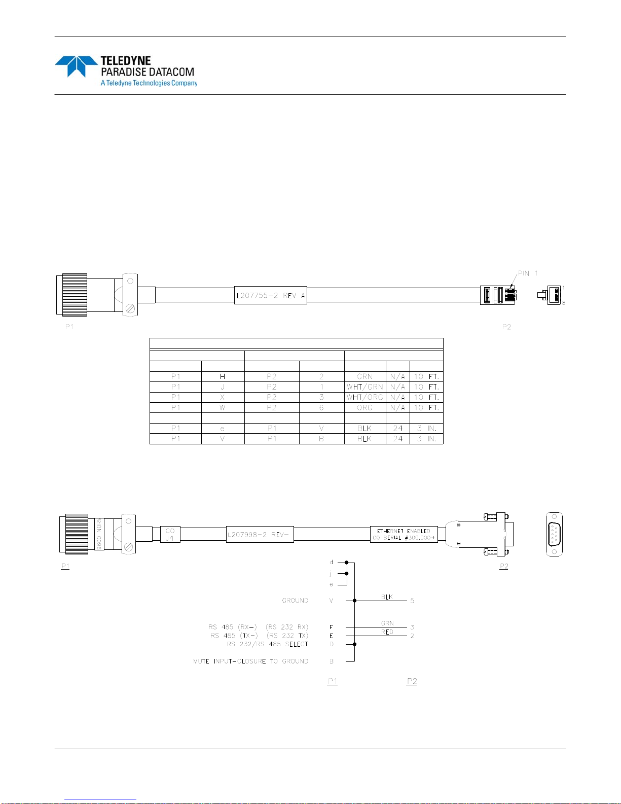
3.1 Quick Start Cables
For convenience all amplifiers ship with a ‘Quick-Start’ communications cable. This allows the
user to immediately connect the amplifier to a PC and begin operation. Ethernet ready units
ship with a Quick Start cable fitted with a 10-base T connector as shown in Figure 3-1.
WIRING CHART
FROM
CONNECTOR TERMINAL TERMINALTOCOLOR AWG LENGTH
CONNECTOR
Figure 3-1: Ethernet Quick Start Cable, 207755
Customers may request a Quick Start cable configured for RS-232 communications and fitted
with 9-pin D-sub connector as shown in Figure 3-2.
Figure 3-2: RS-232 Quick Start Cable, 207998
Operations Manual, High Power Outdoor SSPA 211670 REV D 21

3.2 Quick Start Connections
This section describes the necessary steps to communicate with an amplifier using either the
Ethernet or RS-232 Quick Start cables and the Teledyne Paradise Datacom Universal M&C
Software. The Universal M&C Software is a free Windows-based application that can be
downloaded from the company web site, www.paradisedata.com.
Note: The amplifier has no on/off switch or circuit breaker in the AC Input path.
As soon as AC power is applied, the unit’s power supplies and microcontroller
are enabled. However, the RF output of the internal amplifier module is disabled
until the Mute Line Input (J4 – Pin B) is pulled to Ground (J4 – Pin V). Both the
Ethernet Quick Start and RS-232 Quick Start cables provide this connection.
3.2.1 Set PC Configuration
To set your Windows-based PC to remotely communicate with the amplifier, perform the
following steps:
If using Windows XP:
1. Open the PC’s Control Panel (Start Menu → Settings → Control Panel);
2. Double-click on the Network Connections icon;
3. Right-click on the Local Area Connection icon and select Properties;
4. Select Internet Protocol (TCP/IP) and click on the Properties button;
5. Select “Use the following IP address” and enter the following information:
IP address: 192.168.0.1
Subnet mask: 255.255.255.0
6. Click the “OK” button and close out of the Control Panel windows.
If using Windows Vista or Windows 7:
1. Click on the Windows icon in the lower left corner and select Control Panel;
2. Click on the Network and Sharing Center link;
3. Click on the Local Area Connection link;
4. Click on the Properties button;
5. Select Internet Protocol Version 4 (TCP/IP v4) and click on the Properties button;
6. Select “Use the following IP address” and enter the following information:
IP address: 192.168.0.1
Subnet mask: 255.255.255.0
7. Click the “OK” button and close out of all of the Control Panel windows.
3.2.2 Quick Start Ethernet Connection
The following steps outline how to quickly connect to the amplifier using the Ethernet Quick
Start cable.
1. Unpack the amplifier and connect the RF Input and RF Output.
2. Ensure the J1 RF Output port is properly terminated.
3. Connect the chassis ground and provide AC input power to connector J7.
4. When shipped from the factory, the amplifier is set to start up muted.
22 211670 REV D Operations Manual, High Power Outdoor SSPA

5. Connect the supplied “Quick-Start” Control Cable from Port J4 to the Ethernet port
on your computer. This connection will unmute the amplifier. Review the cable
schematic in Figure 3-1.
6. Launch the Windows-based Teledyne Paradise Datacom Universal M&C Software.
IMPORTANT! If the unit is powered up with the Ethernet Quick Start Cable
connected to Port J4, the following default conditions apply to the unit:
IPNET Interface
Gateway: 192.168.0.1
IP Address: 192.168.0.9
Subnet Mask: 255.255.255.0
Local Port: 1007
IP Lock: 255.255.255.255
Web password: paradise
Read Community: public
Write Community: private
Amplifier is unmuted
3.2.3 Quick Start RS-232 Connection
The following steps outline how to quickly connect to the amplifier using the RS-232 Quick
Start cable.
1. Unpack the amplifier and connect the RF Input and RF Output.
2. Ensure the J1 RF Output port is properly terminated.
3. Connect the chassis ground and provide AC input power to connector J7.
4. When shipped from the factory, the amplifier is set to start up muted.
5. Connect the supplied “Quick-Start” Control Cable from Port J4 of the SSPA to one
of the COM ports on your computer. This connection will unmute the amplifier.
Review the cable schematic in Figure 3-2.
6. Launch the Windows-based Teledyne Paradise Datacom Universal M&C Software.
IMPORTANT! If the unit is powered up with the RS-232 Quick Start Cable
connected to Port J4, the following default conditions apply to the unit:
Normal Protocol
RS-232 Communication
Baud rate: 9600
Amplifier is unmuted
Communication Links using RS-232 are typically good up to 30 ft. (9 m) in length. Installations exceeding this length can use the RS-485 mode which will allow serial control up to
4000 ft. (1200 m).
Operations Manual, High Power Outdoor SSPA 211670 REV D 23

3.2.4 Setting Custom IP Address
The following steps show how to set custom IP settings to the amplifier. This procedure
assumes the user has downloaded and installed the Teledyne Paradise Datacom Universal
M&C application.
1. Remove power to the unit.
2. Connect the Quick Start cable (207755) between Port J4 of the unit and the RJ45
Ethernet port on your computer.
3. Ensure the J1 RF Output port is properly terminated.
4. Connect the chassis ground and provide AC input power to connector J7.
5. The amplifier will power up with the default IP settings.
6. Launch the Universal M&C application.
7. Connect to the unit as described in Section 3.3.
8. Navigate to the Settings tab.
9. Set the Protocol to IPNet. With the Quick Start cable attached, the setting will show
that it is set already set to IPNet. You will need to re-select IPNet.
10. Navigate to the IP Setup tab.
11. Modify the IP settings (IP Address, Gateway Address, Subnet Mask, Local Port, IP
Lock Address) to those that will work within your network.
12. Click on the “Change IP Settings” button.
13. Remove the Quick Start cable.
14. Cycle power to the unit.
15. Reconnect the Quick Start cable or other cable to Port J4 of the unit.
IMPORTANT! If the Quick Start cable is attached to Port J4 of the unit
before power is applied, the unit will always start up with the default IP
settings. Teledyne Paradise Datacom recommends that the operator
build a custom cable that leaves Port J4 pins “j” and “e” unpopulated.
This custom cable will prevent the default settings from being used if
the unit experiences an unexpected power cycle.
24 211670 REV D Operations Manual, High Power Outdoor SSPA

3.3 Universal M&C Operation
1. Download and run the Teledyne Paradise Datacom Universal Monitor and Control
Application.
2. Select [Action] → [Add Unit] from the main menu of the Universal M&C Program
and select [Compact Outdoor SSPA] from the menu choices. See Figure 3-3.
Figure 3-3: Universal M&C Add Unit menu
Note: The H-Series High Power Outdoor SSPA uses the same protocol as the
Teledyne Paradise Datacom Compact Outdoor SSPA.
3. A new dialog window will open (see Figure 3-4). Enter the following information
where applicable: Unit ID; if using a RS-232 Connection, the Serial Port and Baud
Rate; or if using an Ethernet Connection, the unit’s IP Address.
Figure 3-4: Add Compact Outdoor SSPA window, via Serial (left) or Internet (right)
4. Specify the unit’s Address in the Amplifier Address box. If you don’t know the address of the unit you may search for it. Be aware that this search feature is only
useful when you have only one unit connected to your PC at a time.
5. If you wish to change the log file location, click on the [Browse] button and navigate
to the desired location. See Section 3.3.4 for more information about the log file.
6. Click on the [Create] button to generate the operation window for this unit.
Operations Manual, High Power Outdoor SSPA 211670 REV D 25
3.3.1.1
3.3.1.5
3.3.1.4
3.3.1.2
3.3.1.3
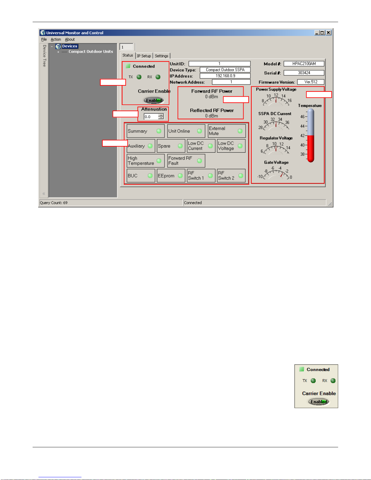
Figure 3-5: Universal M&C Status Window
3.3.1 Universal M&C Status Window
The Universal M&C Software will initialize and open to the Status Window, the main monitor-
ing display. See Figure 3-5. The Status Window shows the current conditions (or state) of the
amplifier. In addition, the status screen allow the user to alter the Mute condition of the carrier
and adjust the on-board Attenuator for gain control.
Upon connection with a unit, the M&C application obtains and displays the unit ID, the amplifier’s model number and serial number. The SSPA module’s firmware version number is also
displayed here for convenience.
The unit’s network address and serial COM or IP address are also listed, which can be helpful in optimizing serial communications.
3.3.1.1 Signal Indicators
Three rows of indicators show the connection status of the connected amplifier. Top-most is an indicator that displays a green square when Connected, or
a red square when Disconnected. Immediately below are two indicators for the
TX and RX paths. The third row displays the mute state (Carrier Enable). The
operator may click on the indicator to toggle between enabling or muting the
amplifier.
26 211670 REV D Operations Manual, High Power Outdoor SSPA
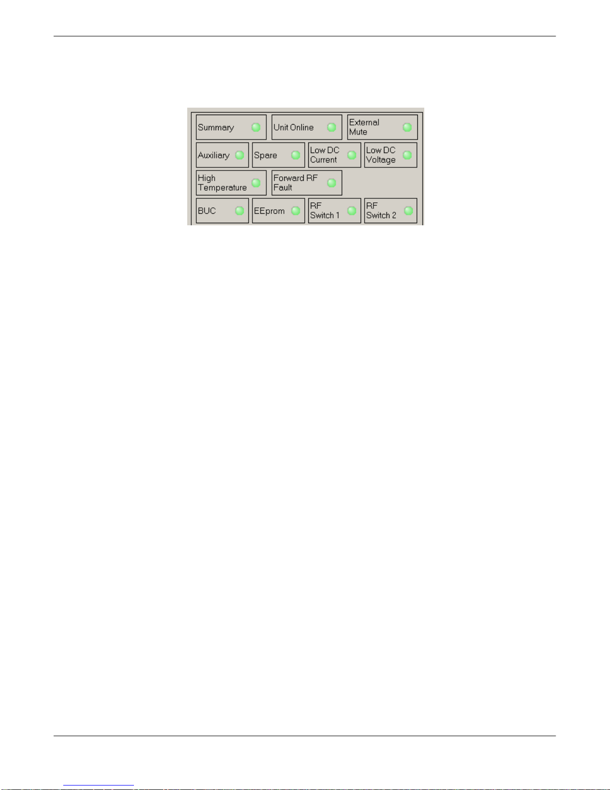
3.3.1.2 Fault Status Indicators
The Fault Status frame in the lower left side of the Status Window contains a 3x4 grid of
SSPA fault lights. See Figure 3-6.
Figure 3-6: Fault Indicators
Summary Alarm: The Summary Alarm is simply a logical ‘OR’ of any major alarm indicators.
Unit Online: This is a status indicator that illuminates green when the unit is online.
External Mute Alarm: The External Mute line gives an indication that the SSPA has been
externally muted by J4-Pin B. This alarm can be configured to trigger a summary alarm if
desired. Factory default is to signal a External Mute fault but no summary alarm.
Auxiliary & Spare Alarms: The Auxiliary and Spare Alarms are configurable from the
Settings Window. These alarms can be configured to trigger a summary alarm. See Section
3.3.2.
Low DC Current Alarm: The Current Fault is factory preset to alarm if the SSPA module cur-
rent falls below 60% of its nominal value. This alarm will also trigger a summary alarm.
Low DC Voltage Alarm: The Voltage Alarm is factory preset to alarm if the SSPA module
current falls below 80% of its nominal value. This alarm will also trigger a summary alarm.
High Temperature Alarm: The Temperature Fault indicator is factory preset to alarm at
80°C. The amplifier will continue to operate up to 90°C. Beyond 90°C the DC power will be
interrupted to the SSPA module. This measure will protect the sensitive microwave transistors from catastrophic failure. The fans and monitor and control circuitry will continue to operate normally. This function has approximately a 5°C hysteresis window which will allow the
amplifier to re-enable itself when the ambient temperature is reduced by 5°C. This alarm will
also trigger a summary alarm.
Forward RF Alarm: The Forward RF Fault Alarm indicates when a the RF output of the am-
plifier falls below the threshold set in the Settings Window.
BUC Alarm: The BUC fault is only active in units that are supplied with an optional L-Band
Block Up Converter module. If the Up Converter’s phase locked local oscillator loses lock, a
BUC alarm is set and the amplifier is muted so that spurious RF cannot be transmitted. This
alarm can be configured to trigger a summary alarm.
Operations Manual, High Power Outdoor SSPA 211670 REV D 27
EEPROM Alarm: The EEPROM Alarm is primarily used as a Fiber RX Link alarm for amplifi-
er units configured with a fiber-optic interface.
RF Switch Alarms: The RF Switch 1 Alarm is only active if a 1:1 Redundant System has
been configured in the M&C program. The RF Switch 2 Alarm is only active is a 1:2 Redundant System has been configured.
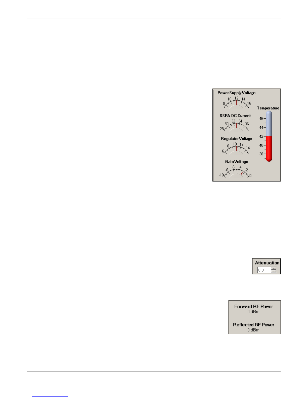
3.3.1.3 Voltage, Current and Temperature Display
On the right side of the Status window is a thermometer display
that reports the present baseplate temperature of the amplifier.
The baseplate temperature typically experiences a 20-30 degree
rise above ambient on the highest power amplifiers and 15-20 degree rise on lower power units.
To the left of the thermometer display are several indicators that
show various operating conditions of the amplifier in real time.
These indicators are helpful for any diagnostic procedures and
consist of:
• Power Supply Voltage monitor
• SSPA DC Current monitor
• Regulator Voltage monitor
• Gate Voltage monitor
The Power Supply voltage indicator displays the primary 25 volt power supply output. SSPA
DC Current is the total current drawn by the microwave transistors. Regulator Voltage is the
DC voltage of the drain circuitry that feeds the GaN transistors. The Gate Voltage indicator
monitors the DC voltage of the gate circuitry of the microwave GaN transistors. These indicators provide direct access to the active device operating characteristics.
3.3.1.4 Gain Adjustment
The Gain Attenuation Control is located above the Fault Condition Indicators and below the
Carrier Enable status. The gain can be adjusted by setting the Attenuation
Control. An Attenuation Control of 0 dB is the maximum gain (75 dB) setting on
the amplifier. By setting the Attenuation Control to 20 dB; the gain is set to 55 dB.
The Attenuation Control can be varied using the control knob or the forward/
reverse buttons to the right of the displayed value.
3.3.1.5 Forward and Reflected RF Power Indicators
The Forward RF Power is displayed in the central part of the Operation
window. This indicator reports the approximate forward output power of
the amplifier. It uses the voltage from the RF Power Detector to determine a corresponding power level in dBm. The accuracy of the power
indicator is ±1 dB at the mid-point of the specified band, with a single CW or QPSK carrier.
Units with the reflected power meter option also display the Reflected RF Power.
28 211670 REV D Operations Manual, High Power Outdoor SSPA
11
1
2
3
4
5
6
7
8
9
10
14
15
12
13
Figure 3-7: Universal M&C Settings Window
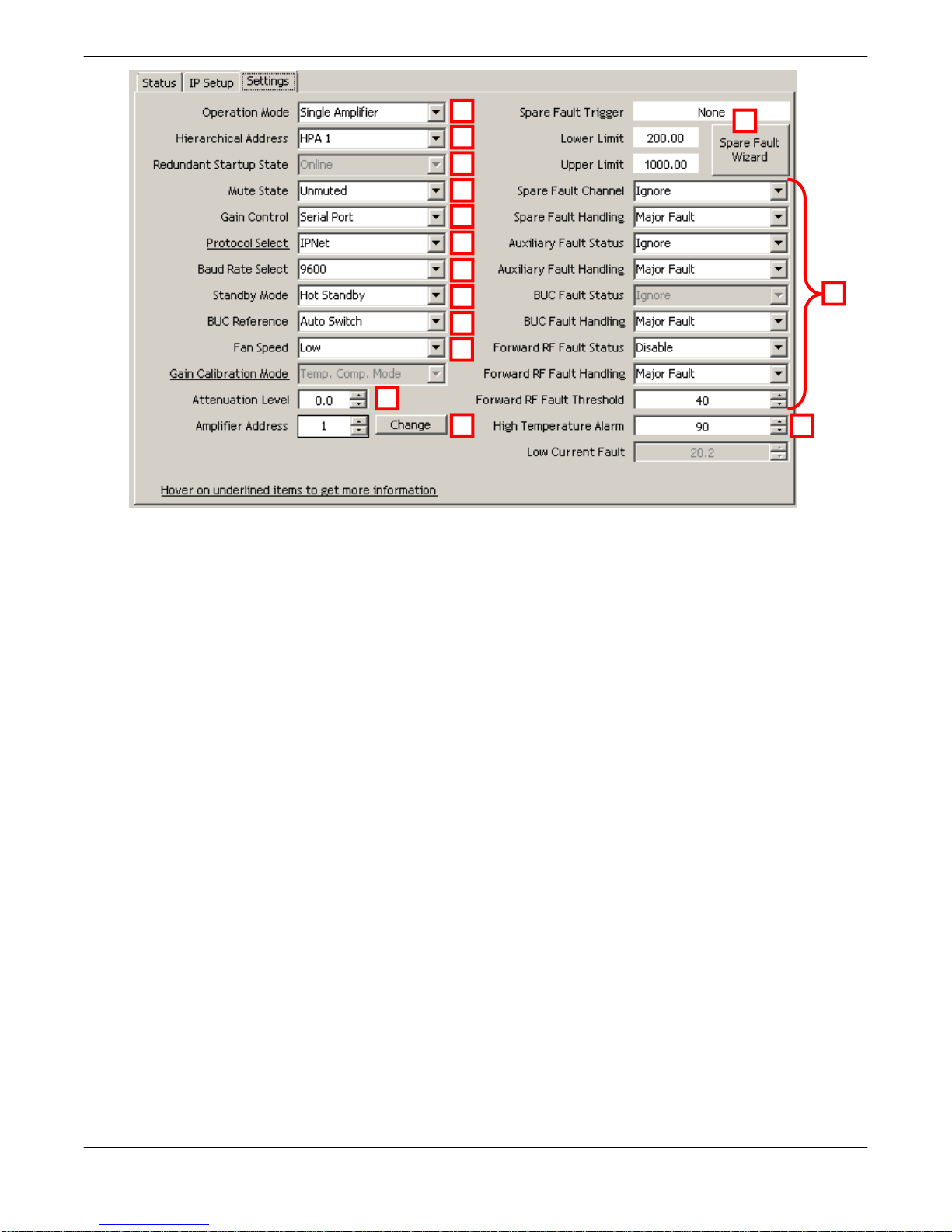
3.3.2 Universal M&C Settings Window
Figure 3-7 shows the Settings tab of the Universal M&C Software. The Settings tab contains
many of the global settings that are available in the SSPA.
3.3.2.1 Power Up Settings
The amplifier will power up with the “last-state” settings before the unit was powered down.
Whatever attenuation setting or mute state the amplifier was in when powered down will be
the restored settings when the amplifier is powered back on.
[1] Operation Mode: Select between stand-alone (single unit) or redundant mode of opera-
tion.
[2] Hierarchical Address: In redundant systems, allows operator to identify an amplifier as
HPA 1 or HPA 2.
[3] Redundant Startup State: In redundant systems, selects whether the unit should start up
as the on-line amplifier or the standby amplifier.
[4] Mute State: Determines if the unit should start up muted (transmit disabled) or mute
cleared (transmit enabled).
[5] Gain Control: Select between serial communication control of the unit’s gain or analog
voltage gain control via J4.
Operations Manual, High Power Outdoor SSPA 211670 REV D 29
[6] Protocol Select: The operator may select either the standard string protocol described in
Section 8 or older generation binary based protocol. The operator will be asked to verify that
the change in Protocol. Communication with the amplifier may be affected.
[7] Baud Rate Select: Sets the baud rate of the unit. The supported baud rates include:
2400, 4800, 9600, 19200, and 38400 baud. The factory default baud rate is 9600. You will be
asked to verify that you wish to change the Baud Rate. Communication with the amplifier may
be affected.
[8] Standby Mode: Selects between Hot and Cold standby mode for units in redundant sys-
tems.
[9] BUC Reference: Selects between an Internal or External reference for an optional block
up converter integrated with the unit, or allows the unit to Auto-switch between Internal and
External reference.
[10] Fan Speed: For units with variable fan speed control, select between Low, High or Auto
fan speed.
[11] Attenuation Level: The Gain Adjustment of the unit is adjustable here, from 0 to 20 in
0.1 dB steps.
[12] Amplifier Network Address: Sets a network address for the unit. Range is 0 to 255.
You will be asked to verify that you wish to change the Amplifier Network Address. Communication with the amplifier may be affected.
[13] Fault Thresholds: Allows the user to set the limit for triggering the unit’s Current Fault or
High Temperature Fault.
Low Current Fault Threshold: This setting is factory pre-set.
High Temperature Alarm Threshold: Range is 0 to 125 °C.
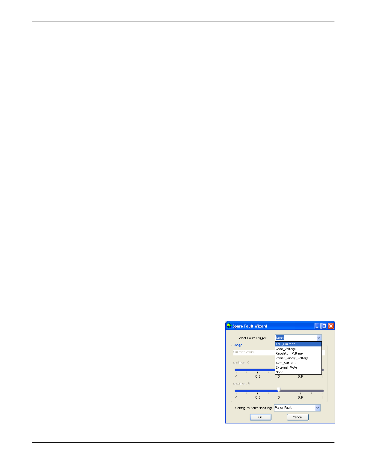
[14] Fault Setup: This feature allows the user to set the Spare Fault Trigger using the Spare
Fault Wizard.
Click on the Spare Fault Wizard button, which opens a
new window. See Figure 3-8. Select between the follow-
ing fault triggers: Analog Gain Adjust Voltage, Gate Voltage, Regulator Voltage, Power Supply Voltage, SSPA
Current, External Mute, or None. Set the range of maximum and minimum thresholds that would trigger the selected fault, and configure the fault handling via a pulldown menu (Major Fault, Minor Fault, Major Fault plus
Mute). Click the OK button to set the fault trigger for the
Spare Fault.
30 211670 REV D Operations Manual, High Power Outdoor SSPA
Figure 3-8: Spare Fault Wizard
 Loading...