


TELEDYNE
HASTINGS
INSTRUMENTS
INSTRUCTION MANUAL
HFM-E-200/HFC-E-202 SERIES
FLOWMETERS/CONTROLLERS
ISO 9001
CERTIFIED
Manual Print History
The print history shown below lists the printing dates of all revisions and addenda created for this
manual. The revision level letter increases alphabetically as the manual undergoes subsequent updates.
Addenda, which are released between revisions, contain important change information that the user
should incorporate immediately into the manual. Addenda are numbered sequentially. When a new
revision is created, all addenda associated with the previous revision of the manual are incorporated into
the new revision of the manual. Each new revision includes a revised copy of this print history page.
Revision A (Document Number 138-102002)............................................................... October 2002
Revision B (Document Number 138-102004)............................................................... October 2004
Revision C (Document Number 138-082005) ................................................................August 2005
Revision D (Document Number 138-032007) .................................................................March 2007
Revision E (Document Number 138-092008)............................................................September 2008
Revision E (Document Number 138-082010)................................................................. August 2010
Visit www.teledyne-hi.com for WEEE disposal guidance.
CAUTION:
CAUTION:
CAUTION:
The ins truments des cribed in this manual are av ailable w ith multiple pin-outs .
Ensure that all electrical connections are correct.
The ins truments des cribed in this manual are des igned for INDOOR us e only .
The instruments described in this manual are designed for Class 2 installations
in accordance with IAW/IPC standards
Hastings Instruments reserves the right to change or modify the design of its equipment without
any obligation to provide notification of change or intent to change.
HFM-E-200/HFC-E-202
Page 2 of 30

Table of Contents
1. INSTALLATION AND OPERATION............................................................................................................................. 4
1.1. FEATURES.................................................................................................................................................................... 4
1.2. SPECIFICATIONS........................................................................................................................................................... 5
1.3. OPTIONAL 4-20 MA CURRENT OUTPUT .......................................................................................................................6
1.4. OTHER ACCESSORIES...................................................................................................................................................6
1.4.1. Hastings Model 40, THPS-100 and THPS-400 Power Supplies.............................Error! Bookmark not defined.
2. INSTALLATION AND OPERATION............................................................................................................................. 7
2.1. RECEIVING INSPECTION ............................................................................................................................................... 7
2.2. POWER REQUIREMENTS ............................................................................................................................................... 7
2.3. OUTPUT SIGNAL...........................................................................................................................................................7
2.4. MECHANICAL CONNECTIONS....................................................................................................................................... 7
2.5. ELECTRICAL CONNECTIONS......................................................................................................................................... 8
2.6. OPERATION.................................................................................................................................................................. 9
2.6.1. Operating Conditions............................................................................................................................................. 9
2.6.2. Zero Check............................................................................................................................................................. 9
2.6.3. High Pressure Operation ..................................................................................................................................... 10
2.6.4. Blending of Gases.................................................................................................................................................10
2.7. OPERATION WITH EXTERNAL DEVICES ...................................................................................................................... 10
2.7.1. Operation with a Hastings power supply.............................................................................................................10
2.7.2. Operation with a power supply other than a Hastings.........................................................................................10
2.7.3. Operation with an external sensor. (Fig. 2.2).................................................................................................... 11
2.7.4. Soft Start...............................................................................................................................................................11
2.8. RANGE CHANGING:.................................................................................................................................................... 11
3. THEORY OF OPERATION...........................................................................................................................................12
3.1. OVERALL FUNCTIONAL DESCRIPTION: ...................................................................................................................... 12
3.2. SENSOR:..................................................................................................................................................................... 12
3.3. ELECTRONICS: ...........................................................................................................................................................12
3.4. SHUNT: ...................................................................................................................................................................... 13
3.5. VALVE:...................................................................................................................................................................... 14
4. MAINTENANCE..............................................................................................................................................................15
4.1. AUTHORIZED MAINTENANCE.....................................................................................................................................15
4.2. TROUBLESHOOTING ................................................................................................................................................... 15
4.3. ADJUSTMENTS...................................................................................................................................................... 16
4.3.1. Calibration Procedure: (Figure 4.1).................................................................................................................... 16
4.3.2. Miscellaneous adjustments................................................................................................................................... 17
4.4. INLET REMOVAL:....................................................................................................................................................... 17
4.5. PRINTED CIRCUIT BOARD REPLACEMENT.................................................................................................................. 17
4.6. SENSOR REPLACEMENT: ............................................................................................................................................17
4.7. ORIFICE CHANGES:.................................................................................................................................................... 17
4.7.1. HFC-E-202 Orifice...............................................................................................................................................18
4.8. REPLACEMENT PARTS ........................................................................................................................................19
5. CONVERSION FACTOR TABLE................................................................................................................................. 20
6. WARRANTY....................................................................................................................................................................24
6.1. WARRANTY REPAIR POLICY ...................................................................................................................................... 24
6.2. NON-WARRANTY REPAIR POLICY .............................................................................................................................24
7. DRAWINGS...................................................................................................................................................................... 25
7.1. NOTES:....................................................................................................................................................................... 25
HFM-E-200/HFC-E-202
Page 3 of 30

1. Installation and Operation
The Hastings HFM-E-200 mass Flow-meter and HFC-E-202 Flow-co n troller are designed to accurately
measure and control mass flow over the range of 10 sccm to 30 slm, without corrections or
compensations for gas pressure and temperature with an accuracy of better than ±1% FS. Hastings mass
flow instruments do not require any periodic maintenance under normal operating conditions with clean
gases. No damage will occur from the use of moderate overpressures (~500 psi/3.45MPa) or overflows.
Instruments are normally calibrated with the appropriate standard calibration gas (nitrogen) then a
correction factor is used to adjust the output for the intended gas
1.1. Features
• LINEAR BY DESIGN. The HFM-E-200/HFC-E-202 series is inherently linear (no linearization circuitry is
employed). Should recalibration in the field be desired (a calibration standard is required), the
customer needs to simply set the zero and span points. There will be no appreciable linearity
change of the instrument when the flowing gas is changed.
• MODULAR SENSOR. The HFM-E-200/HFC-E-202 series incorporates a removable/replaceable sensor
module. Field repairs to units can be achieved with a minimum of producti on line downtime.
• LOW TEMPERATURE DRIFT. The temperature coefficient of span for the HFM-E-200/HFC-E-202
series is typically less than 0.05% of full scale/°C from 10-50°C. The temperature coefficient of zero
is typically less than 0.1 % of reading/°C from 10-50°C.
• CURRENT LOOP. The 4-20 mA option gives the user the advantages of a current loop output to
minimize environmental noise pickup.
HFM-E-200/HFC-E-202
Page 4 of 30

1.2. Specifications
Accuracy.............................................................................................................. ±1% full scale (F.S.)
Repeatability .............................................. <±0.125% of F.S.or ±0.075% of rdg. +0.05% F.S. (max)
Maximum operational pressure .............................................................................500 psi [3.45 MPa]
...................................................................................................(Option-P- up to 1000 psi [6.9 MPa]
Pressure coefficient ..............................................................................<0.0067% of reading/psi (N2)
...............................................................................................See pressure section for pressure errors.
Normal operating temperature ............................................10-50°C in non-condensing environment
Operating temperature limits ......................................................................... 0-60°C non-condensing
Temperature coefficient (zero) ........................................ maximum ±0.085%/°C (from 10 to 50oC)
Temperature coefficient (span) ......................................... maximum ±0.05%/°C (from 10 to 50oC)
Leak integrity .......................................................................................................... <1x10⁻⁹ std. cc/s.
Standard flow ranges .....................................................................5, 10, 20, 50, 100, 200, 500, sccm.
............................................................................................. 1, 2, 5, 10, 20, 30* slpm (N2 equivalent)
Standard output.......................................................................................... 0-5 VDC (load 2k Ohms)
Optional output ..................................4 -20 mA (load < 600 Ohms when loop return is @ common)
........................................................................(600-1200 Ohm load when loop return is @ -15VDC)
Power requirements..............................+(14 to 16) VDC @ 45 mA, -(14 to 16) VDC @ 185 mA
Wetted materials ......................................................................... 302 & 316 stainless steel, nickel 200,
........................................................Viton (optional), 82/18 Au-Ni braze, Kalrez, silver solder (trace)
Attitude sensitivity of zero .................................................. < ±0.25% F.S. for 90° without re-zeroing
................................................................................................................{N2 at 44.7 psia (308 KPa)}
Controller weight ..............................................................................................1.6 lb (0.6 kg) approx.
Meter weight.....................................................................................................1.6 lb (0.6 kg) approx.
Electrical connector ......................................................................................15 pin subminiature “D”
Standard fittings ................................................... 1/4” Swagelok®, 1/8” Swagelok®, VCR®, VCO®
* (Specifications may vary for instruments with ranges greater than 10 slpm)
HFM-E-200/HFC-E-202
Page 5 of 30

1.3. Optional 4-20 mA Current Output
An option to the standard 0-5 VDC output is the 4-20 mA current output that is proportional to flow. The
4 - 20 mA signal is produced from the 0 - 5 VDC output of the Flowmeter. The current loop output is
useful for remote applications where pickup noise could substantially affect the stability of the voltage
output.
The current loop signal replaces the voltage output on pin 3 of the “Edge” connector. The current loop
may be returned to either the power supply ground or the -15 VDC connections on the power supply. If
the current loop is returned to the power supply ground, the load must be between 0 and 600 ohm. If it
is returned to the -15VDC, the load must be between 600 and 1200 ohm. Failure to meet these
conditions will cause failure of the loop transmitter.
The 4-20 mA I/O option can accept a current input. The 0-5 VDC command signal on pin A can be
replaced by a 4-20mA command signal. The loop presets an impedance of 75 ohms and is returned to
the power supply through the valve common.
1.4. Other Accessories
1.4.1. Hastings Power supplies
Hastings Power Pod power supply/display units are available in one and four channel versions. They
convert 100, 115 or 230VAC to the ±15 VDC required to operate the flow meter and provide a digital
indication of the flow rate. Interface terminals for the retransmission of the flow meter analog output
signal are located on the rear of the panel.
The Power Pod 100 and 400 models are built with controllers in mind but will work with meters as well.
The Model 40 is for flow meters only. Throughout this manual, when reference is made to a power
supply, it is assumed the customer is using a Hastings power supply. Hastings PowerPod-100 and
PowerPod-400 power supplies are CE marked, but the Model 40 does not meet CE standards at this time.
The Model 40 and PowerPod-100 are not compatible with 4–20 mA analog signals. With the PowerPod
400, individual channels’ input signals, as well as their commands, become 4–20 mA compatible when
selected. The PowerPod-400 also sports a Totalizer feature. More information about the Power Pods can
be found on the Hastings web site. http://www.teledyne-hi.com/products/powerpod-series.htm
1.4.2. Interconnecting Cables
Cables are available from Hastings, in various lengths, to connect from the 15 pin "D" connector on the
back of the Power Pod directly to any of the 200 series and 300 series flow instruments (including digital
versions). More information about the available cables can be found in the Power Pod 400 bulletin on
the Hastings web site. http://www.teledyne-hi.com/pdfs/bulletins.htm
HFM-E-200/HFC-E-202
Page 6 of 30

2. Installation and Operation
This section contains the necessary steps to assist in getting a new Flowmeter/Controller into operation
as quickly and easily as possible. Please read the following thoroughly before attempting to install the
instrument.
2.1. Receiving Inspection
Carefully unpack the Hastings HFM-E-200/HFC-E-202 series instrument and any accessories that have also
been ordered. Inspect for any obvious signs of damage to the shipment. Imm ediately advise the carrier
who delivered the shipment if any damage is suspected. Check each component shipped with the
packing list. Insure that all parts are present (i.e., Flowmeter, power supply, cables, etc.). Optional
equipment or accessories will be listed separately on the packing list. There may also be one or more
OPT-options on the packing list. These normally refer to special ranges or special ga s calibrations. They
may also refer to special helium leak tests, or high pressure tests. In most cases, these are not separate
parts, but special options or modifications built into the Flowmeter.
2.2. Power Requirements
The HFM-E-200/HFC-E-202 series requires ±15 VDC @ ±50 mA (HFM -E-200) +50 mA, -200 mA (HFC-E-202)
for proper operation. The supply voltage should be sufficiently regulated to no more than 50 mV ripple.
The supply voltage can vary from 14.0 to 16.0 VDC. Surge suppressors are recommended to prevent
power spikes reaching the instrument. The Hastings power supply described in Section 1.4.2 satisfies
these power requirements.
2.3. Output Signal
The standard output of the Flowmeter is a 0-5 VDC signal proportional to the flow rate. In the Hastings
power supply the output is routed to the display, and is also available at the terminals on the rear panel.
If a Hastings supply is not used, the output is available on pin 3 of the “Edge” connector and is
referenced to pin 2. It is recommended that the load resistance be no less that 2kW. If the optional 420 mA output is used, the load impedance must be selected in accordance with Section 1. 3 .
2.4. Mechanical Connections
The Flowmeter may be mounted in any position as long as the direction of gas flow throu gh the
instrument follows the arrow marked on the bottom of the Flowmeter case label. The preferred
orientation is with the inlet and outlet fittings in a horizontal plane (if operating with a dense gas or at
high pressures the instrument must be installed horizontally). When mounted in a different orientation
the instrument should be re-zeroed at zero flow with the system pressurized to the expected operating
pressure.
The smallest of the internal passageways in the HFM-E-200/HFC-E-202 series is the diameter of the
sensor tube, which is 0.0125” (0.31 mm), so the instrument requires adequate filtering of the gas supply
to prevent blockage or clogging of the tube.
The pressure regulator and the plumbing upstream must be of sufficient size to minimize changes in the
upstream pressure. When switching from full flow to zero flow, the inlet pressure of instrument should
rise to no more that 30% above the inlet pressure at full flow. In general, high capacity regulators and
large internal diameter plumbing help to make the system more stable. The pressure drop between the
regulator and the instrument due to line resistance should be minimized. The differential pressure
across the unit should be less than 6” of H
O at maximum flow.
2
There are two 8-32 threaded holes, located on the bottom of the base that can be used to secure it to a
mounting bracket, if desired (screws provided).
The standard inlet and outlet fittings for the 200/202 are 0.25” and 0.125” Swagelok (optional VCR or
VCO fittings). The O-rings for the end cap and the sensor are Viton (optional Kalrez or Neoprene). It is
HFM-E-200/HFC-E-202
Page 7 of 30

suggested that all connections be checked for leaks after installation. This can be done by pressurizing
the instrument (do not exceed 500 psig unless the Flowmeter is specifically rated for higher pressures)
and applying a diluted soap solution to the flow connections rated for higher pressures) and applying a
diluted soap solution to the flow connections.
2.5. Electrical Connections
If a power supply from Hastings Instruments is used, installation consists of connecting the HFM-E200/HFC-E-202 series cable from the “D” connector on the rear of the power supply to the “Edge”
connector on the top of the Flowmeter. If a different power supply is used, follow the instru ctions
below when connecting the flow meter.
This HFM-E-200/HFC-E-202 series requires Hastings cable #65-854. Use of any other cable can severely
damage the instrument and void the warranty. Figure 2.1 shows the schematic layout for connecting the
instrument to an appropriate power supply.
The power supply used must be capable of supplying +15VDC at 50mA and -15VDC at -200mA for each
controller. These voltages must be referenced to a circuit Common terminal. Connect -15VDC to pin F
and +15VDC to pin 4.
Pins 2, B and C are all Commons and they are connected together internally with solder jumpers to
ensure compatibility with legacy flow controllers. At least one of these Common pins must be connected
to the Common pin on the power supply. However for new designs and for installations with long cable
runs between the transducer and the power supply it is recommended that pin C be isolated from the
other Common pins of the transducer and provided a separate wire to connect it to the power supply
Common.
Figure 2.1
This pin carries the valve current and under conditions when the impedance of the wire connecting the
transducer Common to the power supply Common is high, tying these Commons together at the
transducer can create cross-talk that may result in flow instabilities or errors in the Command signal or
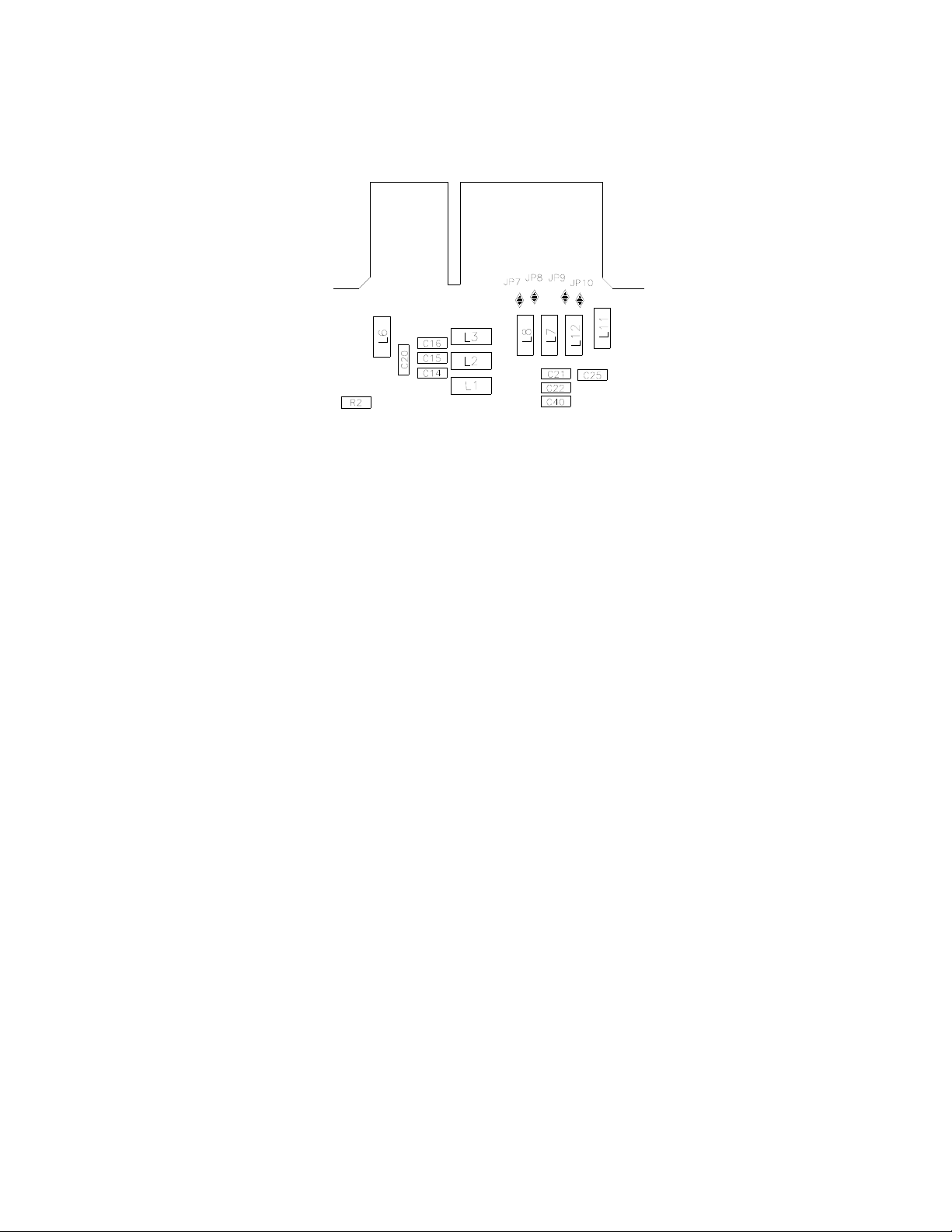
the Flow Output signal. In order to isolate pin C, solder jumpers JP8 and JP10 must be unsoldered while
JP7 remains soldered. This will be performed at assembly time in the factory if there is an indication at
the time of order that this is desired or it can be performed in the field. The Common pins can be
reconfigured to put the valve return current on different pins. Consult factory if it is necessary to match
previously installed wiring.
HFM-E-200/HFC-E-202
Page 8 of 30
Pin 1 is the case ground. It should be connected to the cable shield if available and to the AC ground at
the power supply.
Pin 3 is the output signal from the flow controller. This output will be 0-5VDC, 5VDC being 100% of rated
or full flow. Pin A is the command input. This should be a 0-5VDC signal and must be free of spikes or
other electrical noise, as these will generate false flow commands that the controller would attempt to
flow.
If a valve override switch is not desired, the unit is ready for use at this time. If the override switch is
desired, connect the center pin of a single pole, three-position switch with the center off position to pin
J. Connect +15VDC to one end of the switch, and -15VDC to the other end. This will result in the valve
being full open when +15VDC is supplied to pin J, off when -15VDC is supplied and auto-control when
there is no connection to pin J (OPEN-AUTO-CLOSE). This setup will be adequate for most purposes, but
there will be a small delay for capacitors to charge between switch operation and control override.
2.6. Operation
The standard instrument output is a 0 - 5 VDC out and the signal is proportional to the flow i.e., 0 volts
= zero flow and 5 volts = 100% of rated flow. The 4 - 20 mA option is also proportional to flow, 4 mA =
zero flow and 20 mA = 100% of rated flow. It is suggested that all connections be checked for leaks after
installation. This can be done by pressurizing the instrument (do not exceed 500 psig unless the
instrument is specifically rated for higher pressures) and applying a diluted soap solution to the
connections.
2.6.1. Operating Conditions
For proper operation, the combination of ambient temperature and gas temperature must be such that
the Flowmeter temperature remains between 10 and 50°C. (Most accurate measurement of flow will be
obtained if the Flowmeter is zeroed at operating temperature as temperatur e shifts result in some zero
offset.) The HFM-E-201/HFC-E-203 series is intended for use in non-condensing environments only.
Condensate or any other liquids which enter the Flowmeter may destroy its electronic co mponents.
2.6.2. Zero Check
Turn the power supply on if not already energized. Allow for a 1 hour warm-up. Stop all flow through
the instrument and wait 2 minutes. Caution: Do not assume that all metering valves completely shut
off the flow. Even a slight leakage will cause an indication on the meter and an apparent zero shift. For
the standard 0-5 VDC output, adjust the zero potentiometer located on the lower outlet side of the
Flowmeter until the meter indicates zero. For the optional 4-20 mA output, adjust the zero
potentiometer so that the meter indicates slightly more than 4 mA, i.e. 4.03 to 4.05 mA. This slight
positive adjustment ensures that the 4-20 mA current loop transmitter is not in the cut-off region. The
error induced by this adjustment is approximately 0.3% of full scale. This zero should be checked
HFM-E-200/HFC-E-202
Page 9 of 30

periodically during normal operation. Zero adjustment is required if there is a change in ambient
temperature, or vertical orientation of the Flowmeter/controller.
2.6.3. High Pressure Operation
When operating at high pressure, the increased density of gas will cause natural convection to flow
through the sensor tube if the instrument is not mounted in a level position. This natural convection
flow will be proportional to the system pressure. This will be seen as a shift in the zero flow output that
is directly proportional to the system pressure.
2.6.4. Blending of Gases
In the blending of two gases, it is possible to maintain a fixed ratio of one gas to another. In this case,
the output of one flow controller is used as the reference voltage for the set point potentiometer of a
second flow controller. The set point potentiometer then provides a control signal that is proportional
to the output signal of the first flow controller, and hence controls the flow rate of the second gas as a
percentage of the flow rate of the first gas.
EXAMPLE: Flow controller A has 0-10 slpm range with a 5.00 volt output at full scale. Flow controller B
has 0-1 slpm range with a 5.00 volt output at full scale. If flow controller A is set at 8 slpm, its output
voltage would be 4.00 volts (8 slpm/10 slpm x 5.00 volts = 4.00 volts). If the output signal from flow
controller A is connected to the command potentiometer of flow controller B, it then becomes a variable
reference voltage for flow controller B proportional to the flow rate of flow controller A.
If the set point potentiometer of flow controller B is set at 50% of full scale, and the reference voltage
from flow controller A is 4.00, then the command signal going to flow controller B would be 2.00 volts
(4.00 volts x 50.0% = 2.00 volts). The flow of gas through flow controller B is then controlled at 0.4 slpm
(2.00 volts/5.00 volts x 1 slpm = 0.4 slpm).
The ratio of the two gases is 20:1 (8 slpm/0.4 slpm). The % mixture of g as A is 95.2 (8slpm/84slpm and
the % mixture of gas B is 4.8% (0.4 slpm/8.4 slpm).
Should the flow of flow controller A drop to 7.8 slpm, flow controller B would drop to 0.39 slpm, hence
maintaining the same ratio of the mixture. (7.8 slpm/10 slpm x 5v = 3.90v x 50% = 1.95v; 1.95v/5.00v x 1
slpm = 3.9 slpm; 7.8 slpm: 0.39 slpm = 20:1)
2.7. Operation with External Devices
2.7.1. Operation with a Hastings power supply.
There are two controls for each flow controller connected to a Hastings power supply. A switch labeled
“OPEN; AUTO; CLOSED” (valve over ride THPS 400 only) and a potentiometer labeled “COMMAND”. For
normal operation, the valve over ride switch will be in the “AUTO” position. The “CLOSE” position
removes all power from the valve, shutting off flow regardless of the command pot setting. The “OPEN”
position applies full available valve voltage to the valve, causing it to open, regardless of the command
pot setting. The “OPEN” position is useful for purging systems. It is recommended that the valve over
ride switch not be left in this position for extended periods of time, with no flow through the controller,
as a small positive zero shift may be observed.
The “COMMAND” pot adjusts the Analog command signal sent to the flow controller. The setting for
each controller connected to the power supply can be observed. (Depending on how the power supply
was set up, the display could indicate in flow units or percent of full scale).
2.7.2. Operation with a power supply other than a Hastings.
The flow controller must be connected to the power source as specified in section 2.6. In general, a 0-5
VDC command signal proportional to the intended flow (0 volts = zero flow; 5 volts = 100% of rated flow)
must be applied to pin A of the “Edge” connector. A 0-5 VDC signal proportional to the flow rate
through the instrument will be present on pin 3 of the “Edge” connector. The control mode is selected
via pin J of the “Edge” connector. Apply +15 volts for full open, -15 volts for closed and allow pin J to
float for flow proportional to the command voltage. Refer to your power supply manual f or the specifics
of implementing these parameters.
HFM-E-200/HFC-E-202
Page 10 of 30

2.7.3. Operation with an external sensor. (Fig. 2.2)
In some instances, it might be desirable to use an external sensor to provide process information to the
control circuitry in the flow controller. For example, you might want to control the pressure in a
vacuum system by adjusting the rate at which the system is backfilled with a gas. The new, enhanced
HFC series of flow controllers have provision for accepting a 0-5VDC output from an external sensor at
pin 8 of the “Edge” connector. To activate this feature, the cover of the HFC must be removed to gain
access to PC-888 and move a jumper on JP3. JP3 is a three pin jumper block located just below the
“Edge” connector. In the normal operating mode, the jumper covers the bottom two pins. To select
“External Sensor”, move the jumper to the upper two pins. This swaps the flow input to the controller
circuit from the Flowmeter output to pin 8 of the “Edge” connector.
2.7.4. Soft Start
The response of the control circuit to sudden changes in the Command signal is set at the factory for
fast, stable response and minimal overshoot. If any overshoot is a problem in a particular system, it is
possible to slow down the controller response to sudden Command changes. Remove the outer cover
from the instrument and remove pin jumper JP6 this will insert an R-C filter with a two second time
constant into the command circuit. This will slow down the reaction of the controller to step changes in
the Command signal and will ensure that there is no overshoot or undershoot in actual gas flow.
2.8. Range Changing:
The range of the flow controller can be changed in the field if recalibration facilities are available. The
flow controller may require a different orifice and different laminar Flowmeter element (shunt), which
can be purchased separately from the factory. A listing of the orifices and shunts are available and their
flow rates can be found in Section 4.8.
The range of the small tube shunts can be changes by changing the front disk, consult factory for more
information on disk options.
Figure 2.1
HFM-E-200/HFC-E-202
Page 11 of 30

3. Theory of Operation
This section contains an overall functional description of HFC Flow Contr ollers. Detailed schematics and
parts lists can be found at the end of the manual in Section 6.0. In this section and other sections
throughout this manual, when a power supply is mentioned, it is assumed that the customer has a
Hastings Power Supply. These sections are not applicable if another type of power supply is used.
3.1. Overall Functional Description:
The HFC Flow Controller consists of a sensor, electronic
circuitry, a shunt and a valve. The sensor measures the
flow rate from 0 to 10 sccm of the gas to be metered. The
shunt divides the flow such that the flow through the
sensor is a precise percentage of the flow through the
shunt. The flow through the sensor and the shunt is
always laminar. The circuit board amplifies the sensor
output and uses this output to control the valve position.
The valve is an automatic metering solenoid type; its
height off the seat is controlled by the voltage in its coil.
All of these components working together result in a fast,
stable flow controller.
3.2. Sensor:
Figure 3.1
The Hastings HFM-E-200/HFC-E-202 series operates on a unique thermal electric principle whereby a
metallic capillary tube is heated uniformly by a resistance winding attached to the midpoint of the
capillary (see Figure 3.1). Thermocouples TC-1 and TC-2 are welded at equal distances from the
midpoint and develop equal outputs at zero flow.
When flow occurs through the tubing, heats is transferred from the tube to the gas on the inlet side, and
from the gas back to the tube on the outlet side creating an asymmetrical temperature distribution (see
Figure 3.2). The thermocouples sense this decrease and increase in the capillary tube temperature and
produce a millivolt output signal proportional to that change.
For a constant power input, the differential thermocouple output is a function of the mass flow rate and
the heat capacity of the gas. Since the heat capacity of many gases is relatively constant over wide
ranges of temperature and pressure, the Flowmeter may be calibrated directly in mass units for those
gases. Changes in gas composition usually only require application of a simple multiplier to the air
calibration to account for the difference in heat capacity and thus the Flowmeter is capable of
measuring a wide variety of gases. The HFM sensor measures approximately 10 sccm. Full scale flow.
3.3. Electronics:
The Hastings HFM-E-200/HFC-E-202 series uses a thermal flow sensor to measure through a capillary
tube, which is a fixed percentage of the total flow through the instrument. This sensor develops an
output signal proportional to flow which is approximately 1 mv full scale magnitude. This signal is
amplified by the meter circuitry until is 0-5.00 VDC. This 5 volt output is sent back to the power supply
and to the Flowmeter circuitry, if applicable. At the power supply the 5 volt output is sent to the
terminals on the back and to the decoding circuitry in the display which converts it to a 3-digit output.
The controller circuitry utilizes the Command and the Flow voltages as input signals. The 0-5VDC
command signal is subtracted from the 0-5VDC flow signal creating an error signal. This signal is
amplified and causes the solenoid valve to move. The amount and direction of the movement is
dependent upon the value and the sign of the error signal, and tends to minimize the error signal.
HFM-E-200/HFC-E-202
Page 12 of 30

3.4. Shunt:
Measurement of flow rates higher than the 10 sccm full scale is achieved by dividing the flow with a
fixed ratio shunting arrangement, as is illustrated in Figure 3.3. This is accomplished by placing the
measuring capillary tube parallel with one or more dimensionally similar channels, called a laminar flow
element (LFE). Therefore, the sensor only needs to heat the gas passing through the capillary tube
resulting in low power requirements, while retaining all the mass measuring characterist ics.
The HFM-E-200/HFC-E-202 series has many different shunts. The low range shunt consists of tubes
inserted into a cylindrical base. This shunt is adjustable for ranges from 0-10 sccm to 0-18 0 sccm (see
Figure 3.4). The medium range shunts consists of a piece of stainless steel foil welded to a solid steel
center core. The high range shunts consists of a corrugated stainless steel ribbon wound into a coil and
fused.
Figure 3.2
Figure 3.3
Figure 3.4
Figure 3.5
HFM-E-200/HFC-E-202
Page 13 of 30

3.5. Valve:
The control valve is an “automatic metering solenoid” valve. While most solenoids operate in either the
fully open or fully closed state, the automatic metering solenoid valve is designed to control flow (see
Figure 3.6). A spring, connected to the plunger assembly, holds a magnetic plunger tightly against an
orifice to shut off flow. The magnetic plunger is surrounded by an electrical coil, which when energized
with electrical current lifts the plunger off the orifice and allows flow to pass between the orifice and
the plunger seat. Controlling the current through the coil controls the distance between the orifice and
the plunger seat, thus effectively controlling the flow through the valve. This current is controlled by a
feedback loop that matches the transducer output with the command voltage.
Figure 3.6
HFM-E-200/HFC-E-202
Page 14 of 30

4. Maintenance
This section contains service and calibration information. Some portions of the instrument are delicate.
Use extreme care when servicing the flow controller. The potentiometer positions and the electrical
components referred to in the troubleshooting section can be found in Section 6.0 on the electrical
component layout drawing.
4.1. Authorized Maintenance
With proper care in installation and use, the flow controller will require little or no maintenance. If
maintenance does become necessary, most of the instrument can be cleaned or repaired in the field.
Some procedures may require recalibration. Do not attempt these procedures unless facilities are
available. Entry into the sensor or tampering with the printed circuit board will void warranty. Do not
perform repairs on these assemblies while unit is still under warranty.
4.2. Troubleshooting
SYMPTOM: Output reads 40% of flow with no flow. Zero pot has no effect.
CAUSE: Power supply locked up or shorted out.
ACTION: Turn off power supply for a few seconds, then turn back on. If this proves ineffective,
disconnect the unit from the power supply. If power supply display does not return to zero, then a
regulator chip in the power supply is probably burned out. Check supply voltages and replace faulty
regulator. If display returns to zero after disconnecting the power supply from the unit there is a short
in the unit to ground. Check capacitors C38 & C39 first.
SYMPTOM: Command is zero, but flow remains.
CAUSE: Orifice out of adjustment or faulty op-amp
ACTION: Check valve voltage at connector pins C & D. If voltage is less than 3.00 VDC, then turn orifice
clockwise until flow stops. If voltage is greater than 3.00 VDC. Replace PC Board.
SYMPTOM: Output of unit is proportional to flow but extremely small and not correctable by span pot.
CAUSE: Sensor is not being heated.
ACTION: Unplug connector J2. Check the following resistance: The resistance between pins 2 & 3 of
the sensor should be approximately 2500 ohms (see Figure 3.1 on page 8). The resistance between pins 1
& 4 should be approximately 2.3 ohms. The resistance between pins 2 & 3 and the base of the sensor
should be essentially infinite. If not, replace the sensor unit. If sensor reads O.K., check the voltage
output on pins 2 & 3 of the jack in the board. If it does not read approximately 22 VDC then replace PC
Board.
SYMPTOM: Sensor has proper resistance readings, but little or no output with flow.
CAUSE: Plugged sensor.
ACTION: Shut off gas supply and power supply. Remove cover and PC board from unit. Remove sensor
assembly and examine. If sensor has evidence of plugging, clean or replace as applicable
HFM-E-200/HFC-E-202
Page 15 of 30

SYMPTOM: Flow controller oscillates.
CAUSE: Flow controller not adjusted for the dynamics of the flow system.
ACTION: Check upstream and downstream pressures. The gas supply regulator should not have
excessive lockup when flow shuts off. Also ensure that there is not a large drop in pressure between the
regulator and the instrument due to line resistance. Oscillations can also be caused if a large flow
restriction is pneumatically close to the downstream end of the flow controller. The differential
pressure across the unit must be between the values specifications on the original order.
SYMPTOM: Little or no flow, even with a maximum SetPoint value.
CAUSE: Plugged orifice.
ACTION: Verify the presence of a pressure across the instrument. If present, shut off gas supply and
power supply. Remove orifice per Section 4.9. Examine orifice. If plugged, clean or replace as
applicable. Reassemble valve.
SYMPTOM: Flowmeter reads other than 0.00 VDC with no flow, or there is a small flow when Flowmeter
reads 0.00 VDC.
CAUSE: ZERO potentiometer is out of adjustment.
ACTION: Shut off all flow. Adjust ZERO potentiometer until output reads 0.00 VDC.
SYMPTOM: Flowmeter out of calibration and nonlinear.
CAUSE: Leaks in gas inlet or outlet fittings.
ACTION: Check all fittings for leaks by placing soap solution on all fittings between gas supply and final
destination of gas. Check Flowmeter for leaks. Replace “O” rings if required or recalibrate as
necessary.
4.3. ADJUSTMENTS
4.3.1. Calibration Procedure: (Figure 4.1)
NOTE: Adjusting the SPAN pot will require the use of a
calibration reference in Step 5.
1. Connect power cable to Edge Connector as specified in Section
2.7. Allow instrument to warm up for 30 minutes. Ensure that for at
least the last 3 minutes there is a controlled flow of gas thought the
instrument, shut off gas flow, wait 2 minutes.
2. Set ZERO (R19) potentiometer for 0.000 VDC output.
Span
Zero
3. Turn on gas supply to inlet of instrument. Put Valve Override
switch into CLOSE position. Adjust the orifice underneath controller
to obtain zero flow. Put Valve Override switch into AUTO. Ensure that
full range flow can still be obtained at minimum inlet pressure.
4. Set command to 100%. Wait 2 minutes; adjust SPAN (R29) pot until the flow reference reads full
scale flow (5.000 VDC). NOTE: Perform this step only if a calibrated reference Flowmeter is available.
5. Record Flowmeter and flow reference outputs for flow rates of 20%, 40%, 60%, 80% and 100%.
HFM-E-200/HFC-E-202
Page 16 of 30

4.3.2. Miscellaneous adjustments
Periodically, during normal operation, the ZERO should be checked and adjusted when required. If the
instrument is not stopping the flow completely when command signal is Zero, the orifice may require
turning approximately 1/8 turn clockwise.
4.4. Inlet Removal:
The fitting on the inlet side must be removed to gain access to the filter or shunt assembly. First shut off
the supply of gas to the instrument. Disconnect the Swagelok fitting on the inlet and outlet sides of the
transducer, and remove it from the system plumbing. Carefully remove the inlet fitting, spring (if
present) and shunt, noting their order and proper orientation. The shunt can be severely damaged if
dropped. Examine the filter and shunt. If either is dirty or blocked, clean or replace as applicable.
Reassembly is the reverse of the removal procedure. Recalibration of the HFC is necessary.
4.5. Printed Circuit Board Replacement
In the unlikely event that the PC board fails, it is easily removed from the instrument and replaced with
a spare to minimize instrument downtime. Replacement of the PC board will require the instrument to
be recalibrated per Section 4.3.1.
Unplug the power cable from the top of the transducer. Remove the two jackscrews next to the “Edge”
connector and the two screws on the sides of the cover. Lift off the cover and unplug the four-wire
sensor plug and the two wire valve plug, noting their orientation prior to removal.
Remove the screw that holds the PC board to the sensor. Troubleshoot or replace as applicable.
Installation is the reverse of the above procedure. Recalibrate if any components were changed or if any
potentiometers were adjusted.
4.6. Sensor Replacement:
If the sensor fails or becomes plugged it can be removed. Remove the cover and the PC board per
Section 4.5 above. Remove the three bolts holding the sensor to the instrument base. Remove the
sensor from the base noting the two O-rings (Parker 2-005, V884-75) between the sensor and the base. If
the sensor is plugged it can be cleaned by running a fine wire (approximately 0.008" diameter) through
the tube. If sensor needs replacement, obtain another from the factory and install it. Ensure that Orings are clean and intact. Install O-rings on seating surface, then carefully place sensor over O-rings
and tighten down the three screws evenly. Replacement of sensor will require recalibration per Section
4.3.1.
4.7. Orifice Changes:
The orifice may require replacement if a flow range change is desired, if a large change in differential
pressures across the valve is desired or in the event that a small orifice becomes plugged. Replacement
orifices can be acquired from the factory. See Section 4.8 for the list of standard orifices and their flow
rates in air.
When using nonstandard pressures or gases that have specific gravities different than air (such as
hydrogen or helium), the diameter of the orifice must be calculated using the following procedure:
A) Determine the minimum expected upstream pressure (Pu) in PSI absolute and the maximum
expected downstream pressure (Pd) in PSI absolute for full flow conditions.
B) If Pu >2Pd, use formula 1; otherwise use formula 2.
HFM-E-200/HFC-E-202
Page 17 of 30

Where:
Formula 1: Formula 2:
Q
σ
D
0028.0
=
Q
P
u
D
=
0014.0
d
Ρ•ΔΡ
σ
D = Diameter in inches
Q = Flow rate in standard liters per minute
P = Pu - Pd in PSI
Pu = Upstream pressure in PSIA
Pd = Downstream pressure in PSIA
σ = Specific gravity of gas
Choose the orifice form Section 5.0 that has the closes larger diameter to the calculated diameter.
4.7.1. HFC-E-202 Orifice
To change the orifice in the HFC-E-202 series, turn the instrument upside-down and turn the orifice
counterclockwise with a 9/64” Allen wrench until it stops coming out. Then grasp the exposed orifice
end and pull it straight out. See Figure 4.2.
ORIFICE
(see P/L per P/#
Prior to reinstallation of the orifice, inspect the two O-rings mounted on it for damage. Replace if cut or
gouged.
Lubricate the O-rings slightly with a silicone based grease, and the threads with anti-galling compound.
Push the orifice into its hole and screw it in until it is flush with the instrument base. Apply pressure to
the inlet side of the instrument.
Turn the Valve Override switch to CLOSE or unplug the instrument. Screw the orifice in a few more turns
until the flow through the instrument stops, then turn it an additional 1/8 turn clockwise.
PARKER O-RING
#2-008 VITON
Fig 4.2
HFM-E-200/HFC-E-202
Page 18 of 30

4.8. REPLACEMENT PARTS
The following is a list of the available replacement parts and their factory stock numbers. The HFM-E200 and the HFC-E-202 shunts and sensor modules are interchangeable.
STOCK NO. DESCRIPTION AIR RANGE
81-270 30L - Shunt 24 - 36
81-269 20L - Shunt 16 – 24
81-268 10L - Shunt 8 – 12
81-267 5L - Shunt 4 – 6
81-266 2L - Shunt 1.6 - 2.4
1L - Shunt 0.8 – 1.2
81-265 500sccm - Shunt 400 – 600
81-263 150sccm - Shunt 120 – 180
81-262 70sccm - Shunt 60 – 132
81-261 20sccm - Shunt 12 – 60
81-260 10sccm - Shunt 8 – 12
28-13-298 Orifice 0.001”
28-13-299 Orifice 0.002”
28-13-167 Orifice 0.003”
28-13-168 Orifice 0.007”
28-13-169 Orifice 0.014”
28-13-171 Orifice 0.032”
28-13-172 Orifice 0.052”
28-13-173 Orifice 0.070”
81-314 SENSOR MODULE ALL MODELS
NOTE: Ranges listed are for Nitrogen.
To place an order or to obtain information concerning replacement parts, contact the factory or our
local manufacturer’s representative in you area. See below, or this manual’s last page for the address
or phone number. When ordering, include the following information:
Instrument model number
Part description
Hastings part number
HFM-E-200/HFC-E-202
Page 19 of 30

5. Conversion Factor Table
Rec
# Gas Symbol GCF Derived Density Density Synonyms Gamma R Z
(g/L)
25°C
/ 1 atm / 1 atm 25 J/gm*K
1 Acetic Acid C
2 Acetic Acid, Anhydride C
3 Acetone C
4 Acetonitryl C
5 Acetylene C
0.4155 4 2.700 - 2.947 - Ethanoic Acid 1.2 125.88 2.0301
2H4F2
0.2580 4 4.173 - 4.555 - Aceticanhydride 1.2 81.44 2.3384
4H6O3
O 0.3556 4 2.374 - 2.591 - 2-propanone 1.2 143.16 1.7504
3H6
N 0.5178 4 1.678 - 1.832 - Methyl Cyanide 1.2 202.54 1.4462
2H3
0.6255 4 1.064 - 1.162 - Ethyne 1.23 319.33 0.9792
2H2
6 Air Air 1.0015 1 1.185 - 1.293 - NA 1.4 287.00 1.0930
7 Allene C
8 Ammonia NH
0.4514 4 1.638 - 1.787 - Propadiene 1.2 207.53 1.3876
3H4
0.7807 2 0.696 - 0.760 - NA 1.32 488.21 0.6409
3
9 Argon Ar 1.4047 1 1.633 - 1.782 - NA 1.66 208.13 2.1243
10 Arsine AsH
11 Benzene C
12 Boron Trichloride BCl
13 Boron Triflouride BF
14 Bromine Br
15 Bromochlorodifluoromethane CBrClF
16 Bromodifluoromethane CHBrF
17 Bromotrifluormethane CBrF
18 Butane C
19 Butanol C
20 Butene C
21 Carbon Dioxide CO
22 Carbon Disulfide CS
0.7592 5 3.186 - 3.478 - NA 1.2 106.67 4.0839
3
0.3057 4 3.193 - 3.485 - NA 1.2 106.44 2.0636
6H6
0.4421 4 4.789 - 5.228 - NA 1.2 70.96 3.6531
3
0.5431 4 2.772 - 3.025 - NA 1.2 122.62 2.4109
3
0.8007 4 6.532 - 7.130 - NA 1.4 52.03 1.0000
2
0.3684 4 6.759 - 7.378 - NA 1.2 50.28 4.2789
2
0.4644 4 5.351 - 5.841 - NA 1.2 63.51 4.3990
2
0.3943 4 6.087 - 6.644 - NA 1.2 55.84 4.1546
3
0.2622 2 2.376 - 2.593 - NA 1.09 143.05 1.6896
4H10
O 0.2406 4 3.030 - 3.307 - 1-Butanol, Butyl Alcohol 1.2 112.17 1.9233
4H10
0.3056 4 2.293 - 2.503 - 1-Butene, 1-Butylene 1.2 148.19 1.6700
4H8
0.7526 1 1.799 - 1.964 - NA 1.22 188.93 1.7511
2
0.6160 4 3.112 - 3.397 - NA 1.2 109.20 3.0744
2
23 Carbon Monoxide CO 1.0012 4 1.145 - 1.250 - NA 1.4 296.84 1.0433
24 Carbon Tetrachloride CCl
0.3333 4 6.287 - 6.863 - Tetrachloromethane 1.2 54.05 3.6196
4
25 Carbonyl Sulfide COS 0.6680 4 2.456 - 2.680 - Carbon Oxysulfide 1.2 138.40 2.4230
26 Chlorine Cl
27 Chlorine Trifluoride ClF
28 Chlorobenzene C
29 Chlorodifluoroethane C
30 Chloroform CHCl
31 Chloropentafluoroethane C
32 Chloropropane C
33 Cisbutene C
34 Cyanogen C
0.8451 4 2.898 - 3.163 - NA 1.4 117.26 3.9995
2
0.4496 5 3.779 - 4.125 - NA 1.2 89.94 2.8970
3
Cl 0.2614 4 4.601 - 5.022 - NA 1.2 73.87 2.4954
6H5
ClF2 0.3216 4 4.108 - 4.484 - Ethane, 2-chloro-1,1-difluoro- 1.2 82.74 2.5119
2H3
0.4192 4 4.879 - 5.326 - Trichloromethane 1.2 69.65 3.5284
3
ClF5 0.2437 4 6.314 - 6.892 - NA 1.2 53.83 2.9778
2
Cl 0.3080 4 3.210 - 3.504 - Propylchloride 1.2 105.86 2.0756
3H7
0.3004 4 2.293 - 2.503 - Cis-2-butene 1.2 148.19 1.6672
4H8
0.4924 4 2.127 - 2.322 - NA 1.2 159.79 1.7626
2N2
35 Cyanogen Chloride ClCN 0.6486 5 2.513 - 2.743 - NA 1.2 135.26 2.4405
36 Cyclobutane C
37 Cyclopropane C
38 Deuterium H
39 Diborane B
0.3562 4 2.293 - 2.503 - Tetramethylene 1.2 148.19 1.7091
4H8
0.4562 4 1.720 - 1.877 - Trimethylene 1.2 197.59 1.4440
3H6
2
1.0003 4 0.165 - 0.180 - D2 1.4 2062.13 0.3102
2
0.5063 5 1.131 - 1.235 - NA 1.2 300.49 1.0486
2H6
40 Dibromodifluoromethane CBr2F2 0.3590 4 8.576 - 9.361 - NA 1.2 39.63 5.2998
41 Dichlorofluoromethane CHCl
42 Dichloromethane CH
43 Dichloropropane C
44 Dichlorosilane H
45 Diethyl Amine C
46 Diethyl Ether C
47 Diethyl Sulfide C
F 0.4481 4 4.207 - 4.592 - R21 1.2 80.78 3.2249
2
0.5322 4 3.472 - 3.789 - Methylene Chloride 1.2 97.90 3.0592
2Cl2
0.2698 4 4.618 - 5.041 - 1,2-dichloropropane, 1.2 73.59 2.5291
3H6Cl2
SiCl2 0.4716 5 4.129 - 4.506 - NA 1.2 82.32 3.3176
2
N 0.2256 4 2.989 - 3.263 - NA 1.2 113.68 1.9080
4H11
O 0.2235 4 3.030 - 3.307 - 1,1-oxybisethane 1.2 112.17 1.9215
4H10
S 0.2255 4 3.686 - 4.024 - 3-thiapentane, UN-2375 1.2 92.19 2.1300
4H10
(g/L)
(Cp/Cv)
0°C
HFM-E-200/HFC-E-202
Page 20 of 30

48 Difluoroethylene C2H2F2 0.4492 4 2.617 - 2.857 49 Dimethylamine C
50 Dimethyl Ether C
51 Dimethyl Sulfide C
52 Divinyl C
53 Ethane C
N 0.3705 4 1.843 - 2.011 - N-methylmethanamine 1.2 184.42 1.4793
2H7
O 0.4088 4 1.883 - 2.055 -
2H6
S 0.3623 4 2.540 - 2.772 -
2H6
0.3248 4 2.211 - 2.413 - 1,3-butadiene 1.2 153.71 1.6433
4H6
0.4998 2 1.229 - 1.342 - NA 1.19 276.51 1.1175
2H6
Difluoroethene 1.2 129.85 2.0457
Methylether; Methane,
Oxybis- 1.2 180.48 1.5211
2-thiopropane,
Thiobismethane 1.2 133.81 1.8455
Ethane, 1-chloro-1,1,2,2-
Vinylidenefluoride, G-1132A,
54
tetrafluoro-
HClF4 0.2684 4 5.578 - 6.089 - Chlorotetrafluoroethane 1.2 60.92 2.8629
C
2
Ethane, 1-chloro-1,2,2,2-
55
tetrafluoro- C
56 Ethanol C
57 Ethylacetylene C
58 Ethyl Amine C
59 Ethylbenzene C
60 Ethyl Bromide C
61 Ethyl Chloride C
62 Ethyl Fluoride C
63 Ethylene C
64 Ethylene Dibromide C
65 Ethylene Dichloride C
66 Ethylene Oxide C
67 Ethyleneimine C
68 Ethylidene Dichloride C
69 Ethyl Mercaptan C
70 Fluorine F
71 Formaldehyde CH
72 Freon 11 CCl
73 Freon 12 CCl
74 Freon 13 CClF
HClF4 0.2719 4 5.578 - 6.089 - Chlorotetrafluoroethane 1.2 60.92 2.8806
2
O 0.4046 4 1.883 - 2.055 - Ethyl Alcohol 1.2 180.48 1.5187
2H6
0.3256 4 2.211 - 2.413 - 1-butyne 1.2 153.71 1.6438
4H6
N 0.3694 4 1.843 - 2.011 - Ethanamine 1.2 184.42 1.4789
2H7
0.2001 4 4.339 - 4.737 - 1-butyne 1.2 78.32 2.3099
8H10
Br 0.4124 4 4.454 - 4.862 - NA 1.2 75.60 3.1724
2H5
Cl 0.4212 4 2.637 - 2.878 - Chloroethane 1.2 128.88 2.0018
2H5
F 0.4430 4 1.964 - 2.144 - Fluoroethane, R-161 1.2 173.00 1.5967
2H5
0.6062 1 1.147 - 1.252 - Ethene 1.21 296.38 1.0475
2H4
0.3173 4 7.679 - 8.382 - 1,2-dibromoethane 1.2 44.26 4.1196
2H4Br2
0.3475 4 4.045 - 4.415 - 1,2-dichloroethane 1.2 84.02 2.5846
2H4Cl2
O 0.5308 4 1.801 - 1.965 - Acetaldehide 1.2 188.74 1.5495
2H4
N 0.4790 4 1.719 - 1.877 - Aziridine 1.2 197.71 1.4552
2H4
0.3506 4 4.045 - 4.415 - 1,1-dichloroethane 1.2 84.02 2.5976
2H4Cl2
S 0.3654 4 2.540 - 2.772 - Ethanethiol 1.2 133.81 1.8499
2H6
0.9115 4 1.553 - 1.695 - NA 1.4 218.82 1.5574
2
O 0.7912 4 1.227 - 1.340 - NA 1.2 276.91 1.1232
2
F 0.3535 4 5.615 - 6.129 - Trichloro,fluoromethane 1.2 60.53 3.4473
3
0.3712 4 4.942 - 5.395 - Dichloro,difluoromethane 1.2 68.76 3.2026
2F2
0.3792 4 4.270 - 4.661 - Chloro, trifluoromethane 1.2 79.60 2.8572
3
Carb. Tetrafluoride, Meth.
75 Freon 14 CF
76 Freon 22 CHClF
77 Freon 23 CHF
0.4422 4 3.597 - 3.926 -
4
0.4857 4 3.534 - 3.858 - Chloro, difluoromethane 1.2 96.16 2.8794
2
0.5282 4 2.862 - 3.124 - Trifluoromethane, Fluoroform 1.2 118.76 2.4487
3
Tetrafluoride 1.2 94.48 2.7242
1,2-dichloro, 1,1,,2,2-
78 Freon 114 C
79 Furan C
0.2327 4 6.986 - 7.626 -
2Cl2F4
O 0.3889 4 2.783 - 3.037 - Oxacylopentadiene 1.2 122.139 2.0253
4H4
tetrafluoroethane
1.2 48.65 3.1174
80 Helium He 1.4005 1 0.164 - 0.179 - NA 1.66 2077.28 0.2304
81 Heptafluoropropane C
82 Hexamethyldisilazane C
83 Hexamethyldisiloxane C
84 Hexane C
85 Hexafluorobenzene C
86 Hexene C
87 Hydrazine N
88 Hydrogen H
0.1987 4 6.950 - 7.586 - Freon 227, R-227ea 1.2 48.90 2.9681
3HF7
NSi2 0.1224 4 6.597 - 7.201 - HMDS 1.2 51.52 3.2710
6H19
OSi2 0.1224 4 6.637 - 7.245 - NA 1.2 51.20 3.2794
6H18
0.1828 4 3.522 - 3.845 - NA 1.2 96.48 2.1062
6H14
0.1733 4 7.605 - 8.301 - Perfluorobenzene 1.2 44.69 3.0771
6F6
0.1918 4 3.440 - 3.755 -
6H12
0.5506 4 1.310 - 1.430 - NA 1.2 259.46 1.1757
2H4
1.0038 1 0.082 - 0.090 - NA 1.38 4124.51 0.3895
2
1-Hexene, 4-Methyl, 1Pentene
1.2 98.79 2.0677
89 Hydrogen Bromide HBr 1.0028 4 3.307 - 3.610 - NA 1.38 102.76 7.6975
90 Hydrogen Chloride HCl 1.0034 4 1.490 - 1.627 - NA 1.4 228.04 1.5183
91 Hydrogen Cyanide CHN 0.7772 4 1.105 - 1.206 - Hydrocyanic Acid 1.2 307.66 1.0003
92 Hydrogen Fluoride HF 1.0039 4 0.818 - 0.893 - NA 1.4 415.59 0.6845
93 Hydrogen Iodide HI 0.9996 4 5.228 - 5.707 - NA 1.4 65.00 1.0000
94 Hydrogen Selenide H
95 Hydrogen Sulfide H
96 Isobutane C
Se 0.8412 5 3.309 - 3.612 - NA 1.2 102.68 5.1920
2
S 0.8420 4 1.393 - 1.521 - NA 1.2 243.96 1.3174
2
0.2725 2 2.376 - 2.593 - 2-Methylpropane 1.2 143.05 1.6912
4H10
2-methyl-1-propanol,
97 Isobutanol C
98 Isobutene C
O 0.2391 4 3.030 - 3.307 -
4H10
0.2984 4 2.293 - 2.503 - Isobutylene, Methylpropene 1.2 148.19 1.6663
4H8
Isobutyl Alcohol 1.2 112.17 1.9228
HFM-E-200/HFC-E-202
Page 21 of 30

99 Isopentane C5H12 0.2175 4 2.949 - 3.219 - 2-methylbutane 1.2 115.24 1.8975
100 Isopropyl Alcohol C
101 Isoxazole C
102 Ketene C
O 0.2931 4 2.456 - 2.681 - 2- propanol 1.2 138.356 1.7335
3H8
NO 0.4333 4 2.823 - 3.081 - 1-Oxa-2-azacyclopentadiene 1.2 120.39 2.1501
3H3
O 0.5732 4 1.718 - 1.875 - NA 1.2 197.79 1.5127
2H2
103 Krypton Kr 1.4042 4 3.425 - 3.739 - NA 1.6 99.22 1.0000
104 Methane CH
105 Methanol CH
106 Methyl Acetate C
107 Methyl Acetylene C
108 Methylamine CH
109 Methyl Bromide CH
110 Methyl Chloride CH
111 Methylcyclohexane C
112 Methyl Ethyl Amine C
113 Methyl Ethyl Ether C
114 Methyl Ethyl Sulfide C
115 Methyl Fluoride CH
116 Methyl Formate C
117 Methyl Iodide CH
118 Methyl Mercaptan CH
119 Methylpentene C
120 Methyl Vinyl Ether C
0.7787 1 0.656 - 0.716 - NA 1.31 518.28 0.6105
4
O 0.6167 4 1.310 - 1.430 - Methyl Alcohol 1.2 259.49 1.1818
4
0.3083 4 3.028 - 3.305 - Methyl Ethanoate 1.2 112.24 1.9967
3H6O2
0.4430 4 1.638 - 1.787 - Propyne 1.2 207.53 1.3847
3H4
N 0.5360 4 1.269 - 1.386 - Methanamine 1.2 267.72 1.1449
5
Br 0.6358 4 3.881 - 4.236 - NA 1.2 87.58 4.3841
3
Cl 0.6639 4 2.064 - 2.253 - Chloromethane 1.2 164.77 1.9480
3
0.1853 4 4.013 - 4.381 - NA 1.2 84.681 2.2334
7H14
N 0.2692 4 2.416 - 2.637 - 2-propanamine 1.2 140.661 1.7065
3H9
O 0.2844 4 2.456 - 2.681 - Methoxyethane 1.2 138.356 1.7285
3H8
S 0.2743 4 3.113 - 3.398 -
3H8
F 0.7247 4 1.391 - 1.518 - Fluoromethane 1.2 244.31 1.2790
3
0.3975 4 2.455 - 2.679 - Acetic Acid 1.2 188.74 1.8491
2H4O2
I 0.6514 4 5.802 - 6.333 - NA 1.2 58.58 10.2105
3
S 0.5409 4 1.966 - 2.146 - Methanethiol 1.2 172.83 1.6930
4
0.2037 4 3.440 - 3.755 - NA 1.2 98.79 2.0555
6H12
O 0.3435 4 2.374 - 2.591 - NA 1.2 143.16 1.7377
3H6
2-thiabutane,
Methylthioethane 1.2 109.169 1.9816
121 Neon Ne 1.4043 4 0.825 - 0.900 - NA 1.6 412.02 0.6173
122 Nitric Oxide NO 0.9795 4 1.226 - 1.339 - Niutrogen Monoxide 1.4 277.09 1.1430
123 Nitrogen N
124 Nitrogen Dioxide NO
125 Nitrogen Tetroxide N
126 Nitrogen Trifluoride NF
127 Nitromethane CH
1.0000 1 1.145 - 1.250 - NA 1.40 296.80 1.0434
2
0.7604 4 1.880 - 2.053 - NA 1.2 180.73 1.8624
2
0.3395 4 3.761 - 4.105 - NA 1.2 90.36 2.4128
2O4
0.5406 5 2.902 - 3.168 - NA 1.2 117.10 2.5277
3
0.4653 4 2.495 - 2.723 - NA 1.2 136.21 1.9912
3NO2
128 Nitrosyl Chloride NOCl 0.6357 4 2.676 - 2.920 - NA 1.2 127.02 2.6013
129 Nitrous Oxide N
130 n-Pentane C
131 Octane C
132 Oxygen O
133 Oxygen Difluoride F
134 Ozone O
135 Pentaborane B
136 Pentane C
137 Perchloryl Fluoride ClFO
138 Perfluorocyclobutane C
139 Perfluoroethane C
140 Perfluoropropane C
141 Phenol C
142 Phosgene COCl
143 Phosphine PH
144 Phosphorus Trifluoride PF
145 Propane C
146 Propyl Alcohol C
147 Propyl Amine C
148 Propylene C
149 Pyradine C
O 0.7121 1 1.799 - 1.964 - NA 1.2 188.91 1.7098
2
0.2121 4 2.949 - 3.219 - Dimethylpropane 1.2 115.24 1.9008
5H12
0.1386 4 4.669 - 5.096 - NA 1.2 72.788 2.6119
8H18
0.9779 1 1.308 - 1.428 - NA 1.48 259.84 1.2483
2
O 0.6454 4 2.207 - 2.409 - NA 1.2 153.983 2.0766
2
0.7022 4 1.962 - 2.141 - NA 1.2 173.23 1.8868
3
0.1499 5 2.580 - 2.816 - NA 1.2 131.71 1.9855
5H9
0.2175 4 2.949 - 3.219 - NA 1.2 115.24 1.8975
5H12
0.4155 4 4.188 - 4.571 - NA 1.2 81.16 3.0075
3
0.1711 4 8.176 - 8.924 - Octafluorocyclobutane 1.2 41.57 3.1946
4F8
0.2530 4 5.641 - 6.158 - R116, Hexafluoroethane 1.2 60.24 2.8112
2F6
0.1818 4 7.685 - 8.389 - NA 1.2 44.22 3.0998
3F8
O 0.2489 4 3.847 - 4.199 - Hydroxybenzene 1.2 88.348 2.2089
6H6
0.4812 4 4.043 - 4.413 - Carbonyl Chloride 1.2 84.06 3.3063
2
0.7859 5 1.390 - 1.517 - NA 1.2 244.56 1.2956
3
0.4973 5 3.596 - 3.925 - NA 1.2 94.52 2.9936
3
0.3499 1 1.802 - 1.967 - NA 1.13 188.56 1.4516
3H8
O 0.3061 4 2.456 - 2.681 - 1- propanol 1.2 138.356 1.7427
3H8
N 0.2860 4 2.416 - 2.637 - 1-propanamine 1.2 140.661 1.7126
3H9
0.4048 2 1.720 - 1.877 - Propene 1.2 197.59 1.4223
3H6
N 0.3222 4 3.233 - 3.529 - Azine, Azabenzene 1.2 105.114 2.1151
5H5
Difluoromethane, Methylene
150 R32 CH
0.6197 2 2.126 - 2.321 -
2F2
Fluoride 1.2 153.91 1.9458
1,1-Dichloro-2,2,2-
151 R123 C
HCl2F3 0.2583 2 6.251 - 6.823 -
2
trifluoroethane 1.2 54.37 3.0368
HFM-E-200/HFC-E-202
Page 22 of 30

152 R123A C2HCl2F3 0.2699 4 6.251 - 6.823 153 R125 C
154 R134 C
155 R134A C
156 R143 C
0.2826 2 4.906 - 5.355 - Pentafluoroethane 1.2 66.50 2.6844
2HF5
0.2996 4 4.170 - 4.552 - 1,1,2,2-tetrafluoroethane 1.2 78.42 2.4595
2H2F4
0.3110 2 4.170 - 4.552 - 1,1,1,2-tetrafluoroethane 1.2 78.42 2.5001
2H2F4
0.3451 4 3.435 - 3.750 - 1,1,2-trifluoroethane 1.2 95.52 2.2693
2H3F3
trifluoroethane 1.2 54.37 3.1065
1,1,1-trifluoroethane,
1,2-Dichloro-1,2,2-
157 R143A C
158 R152A C
159 R218 C
160 R1416 C
0.3394 4 3.435 - 3.750 -
2H3F3
0.3877 4 2.700 - 2.947 - 1,1-Difluoroethane 1.2 122.18 1.9753
2H4F2
0.1818 4 7.685 - 8.389 - Octafluoropropane 1.2 44.22 3.0998
3F8
F 0.3047 4 4.780 - 5.218 - 1,1-Dichloro-1-fluoroethane, 1.2 71.10 2.7342
2H3Cl2
Methylfluoroform 1.2 95.52 2.2533
161 Radon Rn 1.4043 4 9.074 - 9.905 - NA 1.2 37.45 1.0000
162 Sec-butanol C
163 Silane SiH
164 Silicone Tetrafluoride SiF
165 Sulfur Dioxide SO
166 Sulfur Hexafluoride SF
167 Sulfur Tetrafluoride SF
168 Sulfur Trifluoride SF
169 Sulfur Trioxide SO
170 Tetrachloroethylene C
171 Tetrafluoroethylene C
172 Tetrahydrofuran C
O 0.2327 4 3.030 - 3.307 - 2-butanol, Sec-butyl Alcohol 1.2 112.17 1.9213
4H10
0.6809 5 1.313 - 1.433 - NA 1.2 258.88 1.1934
4
0.3896 5 4.254 - 4.644 - Tetrafluorosilane 1.2 79.89 2.9041
4
0.6878 4 2.619 - 2.858 - NA 1.2 129.78 2.7013
2
0.2701 1 5.970 - 6.516 - NA 1.2 56.93 3.0092
6
0.3752 4 4.417 - 4.821 - NA 1.2 76.94 2.9215
4
0.4368 4 3.640 - 3.974 - NA 1.2 93.36 2.7312
3
0.5397 4 3.273 - 3.572 - NA 1.2 103.85 2.8922
3
0.2926 4 6.778 - 7.399 - NA 1.2 50.14 3.4711
2Cl4
0.3395 4 4.088 - 4.462 - Tetrafluoroethene 1.2 83.13 2.5732
2F4
O 0.3271 4 2.947 - 3.217 - NA 1.2 115.31 1.9924
4H8
2-methyl-2-propanol,
Tertiarey
173 Tert-butanol C
174 Thiophene C
175 Toluene C
176 Transbutene C
177 Trichloroethane C
178 Trichloroethylene C
O 0.2298 4 3.030 - 3.307 -
4H10
S 0.3538 4 2.783 - 3.037 - Thiofuran 1.2 122.14 1.9586
4H4
0.2448 4 3.766 - 4.111 - Methylbutene 1.2 90.24 2.1756
7H8
0.2053 4 2.293 - 2.503 - 2-butene 1.2 148.19 1.6978
4H8
0.3133 4 5.453 - 5.952 - NA 1.2 62.33 3.0712
2H3Cl3
HCl4 0.3423 4 6.820 - 7.444 - NA 1.2 63.28 3.9903
2
Butyl Alcohol
1.2 112.17 1.9210
R113, 1,1,2-trichloro-1,2,2-
179 Trichlorotrifluoroethane C
180 Triethylamine C
181 Trimethyl Amine C
182 Tungsten Hexafluoride WF
183 Uranium Hexafluoride UF
184 Vinyl Bromide C
185 Vinyl Chloride C
186 Vinyl Flouride C
187 Water Vapor H
0.2253 4 7.659 - 8.360 -
2Cl3F3
N 0.1619 4 4.136 - 4.515 -
6H15
N 0.2822 4 2.416 - 2.637 - n,n-dimethylmethanamine 1.2 140.661 1.7109
3H9
0.2453 5 12.174 - 13.288 - NA 1.2 27.92 4.7379
6
0.1859 4 14.389 - 15.706 - Uranium Fluoride 1.2 23.62 4.4681
6
Br 0.4768 4 4.372 - 4.772 - NA 1.2 77.74 3.5770
2H3
Cl 0.4956 4 2.555 - 2.788 - Chloroethylene 1.2 133.04 2.0988
2H3
F 0.5716 5 1.882 - 2.054 - NA 1.2 180.58 1.6528
2H3
O 0.7992 5 0.742 - 0.810 - NA 1.33 461.53 0.6715
2
trifluoroethane 1.2 44.374 3.2607
UN 1296, n,ndiethylethanamine 1.2 82.167 2.3280
188 Xenon Xe 1.4042 4 5.366 - 5.858 - NA 1.6 63.33 1.0000
189 Xylene, m- C
190 Xylene, o- C
191 Xylene, p- C
0.2036 4 4.339 - 4.737 - NA 1.2 78.32 2.3103
8H10
0.1953 4 4.339 - 4.737 - NA 1.2 78.32 2.3108
8H10
0.2028 4 4.339 - 4.737 - NA 1.2 78.32 2.3102
8H10
HFM-E-200/HFC-E-202
Page 23 of 30

6. WARRANTY
6.1. Warranty Repair Policy
Hastings Instruments warrants this product for a period of one year fr om the date of shipment to be free
from defects in material and workmanship. This warranty does not apply to defects or failures resulting
from unauthorized modification, misuse or mishandling of the product. This warranty does not apply to
batteries or other expendable parts, or to damage caused by leaking batteries or any similar occurrence.
This warranty does not apply to any instrument which has had a tamper seal removed or broken.
This warranty is in lieu of all other warranties, expressed or implied, including any implied warranty as
to fitness for a particular use. Hastings Instruments shall not be liable for any indirect or consequential
damages.
Hastings Instruments, will, at its option, repair, replace or refund the selling price o f the pro duct if
Hastings Instruments determines, in good faith, that it is defective in materials or workmanship during
the warranty period. Defective instruments should be returned to Hastings Instruments, shipment
prepaid, together with a written statement of the problem and a Return Material Authorization (RMA)
number.
Please consult the factory for your RMA number before returning any product for repair. Collect freight
will not be accepted.
6.2. Non-Warranty Repair Policy
Any product returned for a non-warranty repair must be accompanied by a purchase order, RMA form
and a written description of the problem with the instrument. If the repair cost is higher, you will be
contacted for authorization before we proceed with any repairs. If you then choose not to have the
product repaired, a minimum will be charged to cover the processing and inspection. Please consult the
factory for your RMA number before returning any product repair.
TELEDYNE HASTINGS INSTRUMENTS
804 NEWCOMBE AVENUE
HAMPTON, VIRGINIA 23669 U.S.A.
ATTENTION: REPAIR DEPARTMENT
TELEPHONE (757) 723-6531
TOLL FREE 1-800-950-2468
FAX (757) 723-3925
E MAIL hastings_instruments@teledyne.com
INTERNET ADDRESS http://www.teledyne-hi.com
Repair Forms may be obtained from the “Information Request” section of the Hastings Instruments web
site.
HFM-E-200/HFC-E-202
Page 24 of 30

7. Drawings
7.1. Notes:
1. Place jumper (Item 42) on pins 4 and 5 of P2 and P3 as shown.
2. Place one on bottom two pins (1 and 2) of JP3.
3. Place one on both pins of JP6.
HFM-E-200/HFC-E-202
Page 25 of 30

HFM-E-200/HFC-E-202
Page 26 of 30

HFM-E-200/HFC-E-202
Page 27 of 30

HFM-E-200/HFC-E-202
Page 28 of 30

HFM-E-200/HFC-E-202
Page 29 of 30

HFM-E-200/HFC-E-202
Page 30 of 30
 Loading...