

Teledyne HDO9000 Operator's Manual
Operator's Manual
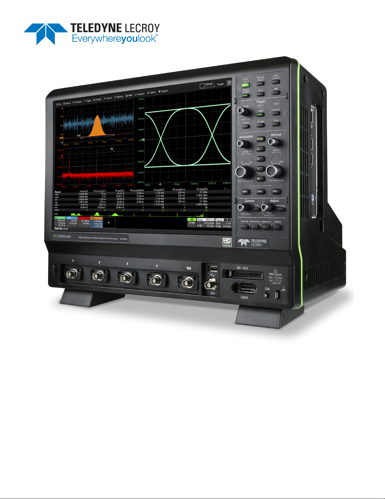
HDO9000
High Definition Oscilloscopes

HDO9000 High Definition Oscilloscopes Operator's Manual
© 2016 Teledyne LeCroy, Inc. All rights reserved.
Unauthorized duplication of Teledyne LeCroy, Inc. documentation materials other than for internal sales and
distribution purposes is strictly prohibited. However, clients are encouraged to duplicate and distribute
Teledyne LeCroy, Inc. documentation for their own internal educational purposes.
HDO and Teledyne LeCroy, Inc. are trademarks of Teledyne LeCroy, Inc., Inc. Other product or brand names
are trademarks or requested trademarks of their respective holders. Information in this publication
supersedes all earlier versions. Specifications are subject to change without notice.
927439 RevA
September 2016

Contents
Safety 1
Symbols 1
Precautions 1
Operating Environment 2
Cooling 2
Calibration 2
Cleaning 2
Power 3
AC Power 3
Power Consumption 3
Ground 3
Oscilloscope Overview 4
Front of Oscilloscope 4
Side of Oscilloscope 5
Back of Oscilloscope 6
Front Panel 7
Top Row Controls 7
Trigger Controls 7
Horizontal Controls 8
Vertical Controls 8
Math, Zoom, and Mem Buttons 8
Cursor Controls 8
Adjust & Intensity 9
Bottom Row Controls 9
Signal Interfaces 10
Analog Inputs 10
Probes 10
LBUS Interface 10
Digital Leadset 11
Oscilloscope Set Up 12
Powering On/Off 12
Software Activation 12
Firmware 12
Purchased Options 12
Connecting to Other Devices/Systems 13
LAN 13
i

HDO9000 High Definition Oscilloscopes Operator's Manual
USB Peripherals 13
Printer 13
External Monitor 13
Remote Control 13
Auxilliary Output 14
Language Selection 14
Using MAUI 15
Touch Screen 15
Menu Bar 15
Grid Area 16
Descriptor Boxes 17
Dialogs 19
OneTouch Help 21
Turn On 21
Activate 21
Copy Setups 22
Change Source 22
Position Cursors 23
Change Trigger 23
Store to Memory 24
Move Trace 24
Scroll 24
Pan Trace 24
Zoom 25
Turn Off 26
Working With Traces 27
Active Trace 27
Foreground Trace 27
Turning On/Off Traces 28
Adjusting Traces 28
Moving Traces 29
Labeling Traces 30
Zooming Traces 31
Print/Screen Capture 35
X-Stream Application Window 35
Acquisition 36
Auto Setup 36
ii

Restore Default Setup 37
Viewing Status 37
Vertical 38
Channel Setup Dialog 38
Cx (Channel) Dialog 39
Probe Dialog 41
Cable De-Embedding Option 42
Digital (Mixed Signal) 43
Digital Traces 43
Activity Indicators 43
Digitalx (Group) Set Up 44
Digital Display Set Up 45
Renaming Digital Lines 46
Timebase 47
Timebase Set Up 47
HD1024 49
Sampling Mode 51
Clock Source Settings 55
History Mode 56
Trigger 58
Trigger Modes 58
Trigger Types 59
Trigger Set Up 60
Trigger Holdoff 67
Software Assisted Trigger 70
TriggerScan 71
Display 73
Multi-Grid Display 73
Q-Scape Multi-Tabbed Display 73
Display Set Up 74
Display Mode (Q-Scape only) 74
Extended Display 75
Grid Mode 76
Grid Intensity 76
Trace Intensity 77
XY Plots 77
Sequence Display Mode 77
iii

HDO9000 High Definition Oscilloscopes Operator's Manual
Persistence Display 78
Apply Persistence 78
Remove Persistence 79
Math and Measure 80
Cursors 80
Cursor Types 81
Apply and Position Cursors 81
Standard Cursors Dialog 82
Measure 83
Measure Table 83
Measure Dialog 84
Parameter Set Up 86
Math on Parameters 89
Using Web Editor 90
Graphing Measurements 94
List of Standard Measurements 100
EMC Pulse Parameter Software Package 104
Calculating Measurements 104
Math 107
Math Function Set Up 108
Math Dialog 109
Average Function 110
Copy Function 111
ERes Function 112
Fast Wave Port Function 114
FFT Function 115
Interpolate Function 116
Sparse Function 117
Rescale Function and Assigning Units 118
List of Standard Operators 120
Memory 122
Saving Memories 122
Restoring Memories 123
Analysis Tools 124
WaveScan 124
Scan Modes 125
Scan Views 127
iv

Setting Up WaveScan 128
Scan Overlay 128
Scan Histogram 129
WaveScan Search 129
Pass/Fail Testing 130
Mask Test Qualifiers 130
Param(eter) Compare Qualifiers 132
Define Pass/Fail Tests 133
Saving Data (File Functions) 134
LabNotebook 134
Create Notebook Entry 134
LabNotebook Drawing Toolbar 135
Manage Notebook Entries 136
Flashback Recall 138
Manage Notebooks 139
Customize Reports 140
LabNotebook Preferences 141
Save / Recall 142
Save Setups 142
Recall Setups 143
Save Waveforms 144
Recall Waveforms 146
Save Table Data 147
Auto Save 148
Utilities 149
Utilities 149
Status 149
Remote Control 150
Hardcopy (Print) 151
Auxiliary Output 154
Date/Time 155
Options 156
Disk Utilities 157
Preferences 158
Acquisition Preferences 159
Calibration 159
E-Mail 161
v

HDO9000 High Definition Oscilloscopes Operator's Manual
Color 162
Miscellaneous 163
Maintenance 164
Touch Screen Calibration 164
Restart/Reboot Instrument 164
Firmware Update 165
Technical Support 166
Phone 166
Web 166
Service Centers 166
Returning a Product for Service 167
Certifications 168
EMC Compliance 168
EC Declaration of Conformity- EMC 168
Australia & New Zealand Declaration of Conformity– EMC 169
Safety Compliance 169
EC Declaration of Conformity– Low Voltage 169
U.S. NationallyRecognized Agency Certification 169
Canadian Certification 170
Environmental Compliance 170
End-of-Life Handling 170
Restriction of Hazardous Substances (RoHS) 170
ISO Certification 170
Warranty 171
Intellectual Property 171
Windows License Agreement 171
Index 172
vi

Welcome
Thank you for purchasing a Teledyne LeCroy High Definition Oscilloscope. We're certain you'll be
pleased with the detailed features unique to our instruments.
The manual is arranged in the following manner:
l Safety contains important precautions and information relating to power and cooling.
l Oscilloscope Overview through Maintenance cover everything you need to know about the
operation and care of the instrument.
Documentation for using software options is available from the Teledyne LeCroy website at
teledynelecroy.com. Our website maintains the most current product specifications and should be
checked for frequent updates.
Take a moment to verify that all items on the packing list or invoice copy have been shipped to you.
Contact your nearest Teledyne LeCroy customer service center or national distributor if anything is
missing or damaged. We can only be responsible for replacement if you contact us immediately.
We truly hope you enjoy using Teledyne LeCroy's fine products.
Sincerely,
David C. Graef
Vice President and General Manager, Oscilloscopes
Teledyne LeCroy
vii

HDO9000 High Definition Oscilloscopes Operator's Manual
viii
Safety
Safety
To maintain the instrument in a correct and safe condition, observe generally accepted safety
procedures in addition to the precautions specified in this section. The overall safety of any system
incorporating this product is the responsibility of the assembler of the system.
Symbols
These symbols appear on the instrument or in documentation to alert you to important safety
considerations:
Caution of potential damage to instrument or Warning of potential bodily injury. Refer to the
accompanying information. Do not proceed until the information is fully understood and conditions
are met.
Caution, high voltage; risk of electric shock or burn.
Caution, contains parts/assemblies susceptible to damage by Electrostatic Discharge (ESD).
Frame or chassis terminal (ground connection).
Alternating current.
Standby power (front of instrument).
Precautions
Caution: Comply with the following instructions to avoid personal injury or damage to your
equipment.
Use indoors only within the operational environment listed. Do not use in wet or explosive
atmospheres.
Maintain ground. This product is grounded through the power cord grounding conductor. To avoid
electric shock, connect only to a grounded mating outlet.
Connect and disconnect properly. Do not connect/disconnect probes, test leads, or cables while they
are connected to a live voltage source.
Observe all terminal ratings. Do not apply a voltage to any input that exceeds the maximum rating of
that input. Refer to the front of the instrument for maximum input ratings.
Use only power cord shipped with this instrument and certified for the country of use.
Keep product surfaces clean and dry. See Cleaning.
Do not remove the covers or inside parts. Refer all maintenance to qualified service personnel.
1
HDO9000 High Definition Oscilloscopes Operator's Manual
Execise care when lifting. Use the built-in carrying handle.
Do not operate with suspected failures. Do not use the product if any part is damaged. Obviously
incorrect measurement behaviors (such as failure to calibrate) might indicate impairment due to
hazardous live electrical quantities. Cease operation immediately and sequester the instrument from
inadvertent use.
Operating Environment
Temperature: 5 to 40° C.
Humidity: Maximum relative humidity 90 % for temperatures up to 31° C, decreasing linearly to 50%
relative humidity at 40° C.
Altitude: Up to 3,000 m at or below 30° C.
Cooling
The instrument relies on forced air cooling with internal fans and vents. Take care to avoid restricting
the airflow to any part. In a benchtop configuration, leave a minimum of 15 cm (6 inches) around the
sides between the instrument and the nearest object. The feet provide adequate bottom clearance.
Follow rackmount instructions for proper rack spacing.
Caution: Do not block the cooling vents.
The instrument also has internal fan control circuitry that regulates the fan speed based on the
ambient temperature. This is performed automatically after start-up.
Calibration
The oscilloscope is calibrated at the factory prior to being shipped. The recommended calibration
interval is one year. Calibration should be performed by qualified personnel only.
Schedule an annual factory calibration as part of your regular maintenance. Extended warranty,
calibration, and upgrade plans are available for purchase. Contact your Teledyne LeCroy sales
representative or customersupport@teledynelecroy.com to purchase a service plan.
The oscilloscope software includes both automatic and user-initiated calibration functions. See
Calibration Preferences.
Caution: Remove all inputs prior to performing calibration.
Cleaning
Clean only the exterior of the instrument using a soft cloth moistened with water or an isopropyl
alcohol solution. Do not use harsh chemicals or abrasive elements. Under no circumstances
submerge the instrument or allow moisture to penetrate it. Dry the instrument thoroughly before
connecting a live voltage source.
2
Safety
Caution: Unplug the power cord from the AC inlet before cleaning to avoid electric shock. Do
not attempt to clean internal parts. Refer all maintenance to qualified service personnel.
Power
AC Power
The instrument operates from a single-phase, 100-240 Vrms (± 10%) AC power source at 50/60 Hz (±
5%) or a 100-120 Vrms (± 10%) AC power source at 400 Hz (± 5%). Manual voltage selection is not
required because the instrument automatically adapts to the line voltage.
Power Consumption
Maximum power consumption with all accessories installed (e.g., active probes, USB peripherals,
digital leadset) is 500 W (500 VA). Power consumption in Standby mode is 15 W.
Ground
The AC inlet ground is connected directly to the frame of the instrument. For adequate protection
again electric shock, connect to a mating outlet with a safety ground contact.
Caution: Only use the power cord provided with your instrument. Interrupting the protective
conductor (inside or outside the case), or disconnecting the safety ground terminal, creates a
hazardous situation. Intentional interruption is prohibited.
3
HDO9000 High Definition Oscilloscopes Operator's Manual
Oscilloscope Overview
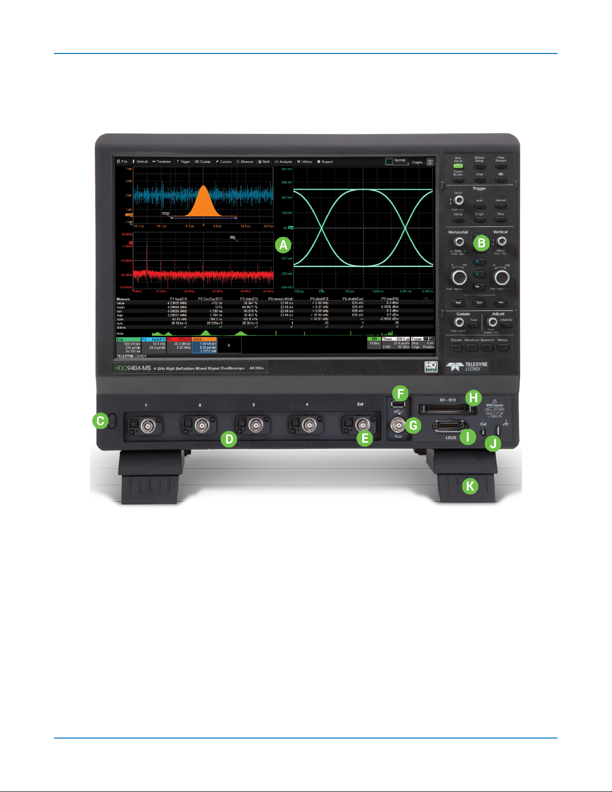
Front of Oscilloscope
A. Capacitive touch screen
display
B. Front panel
C. Power button
D. Channel inputs (C1-C4)
E. Ext input
F. USB 2.0 port
4
G. Aux output
H. Mixed-Signal interface
I. LBUS input
J. Ground and Calibration output
terminals
K. Tilting feet
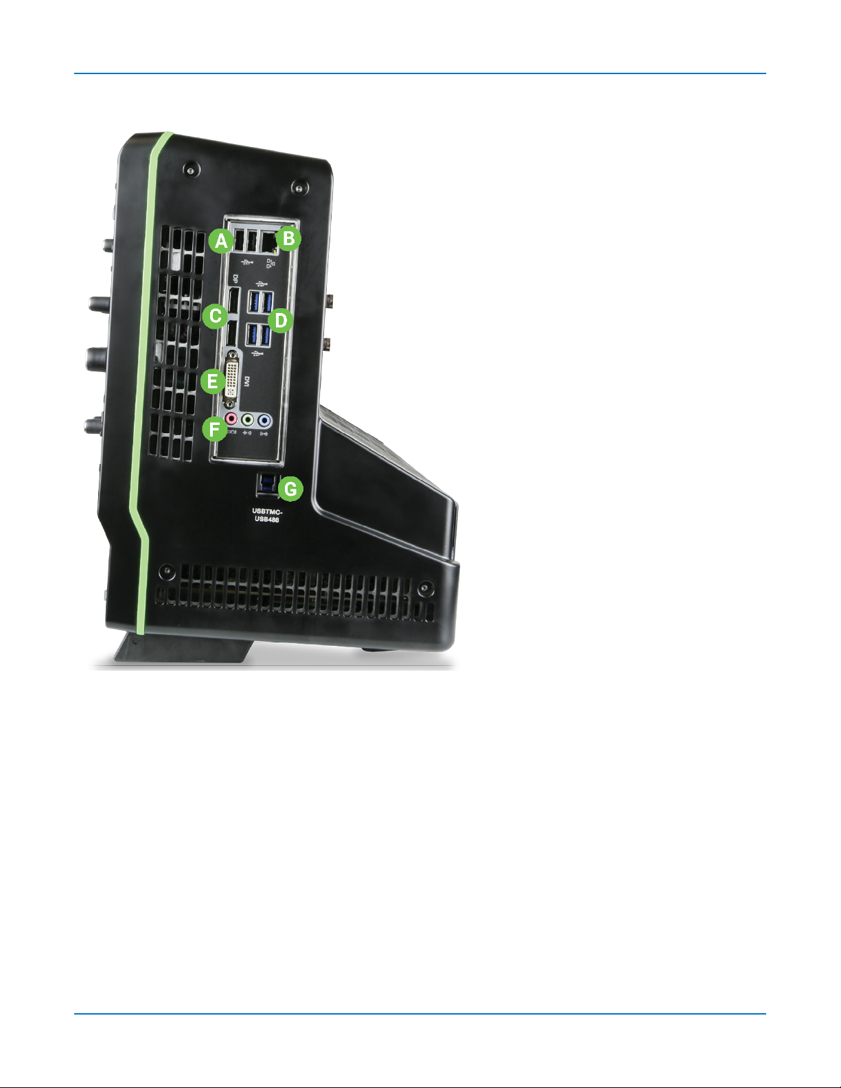
Side of Oscilloscope
Oscilloscope Overview
A. USB 2.0 ports (2)
B. Ethernet port for connecting to LAN or
remote control
C. DisplayPort ports (2) for connecting
external monitor
D. USB 3.1 ports (4)
E. DVI port for external monitor
F. Audio In/Out (mic, speaker, and line-in)
for connecting external audio devices
G. USBTMC port for remote control
5
HDO9000 High Definition Oscilloscopes Operator's Manual
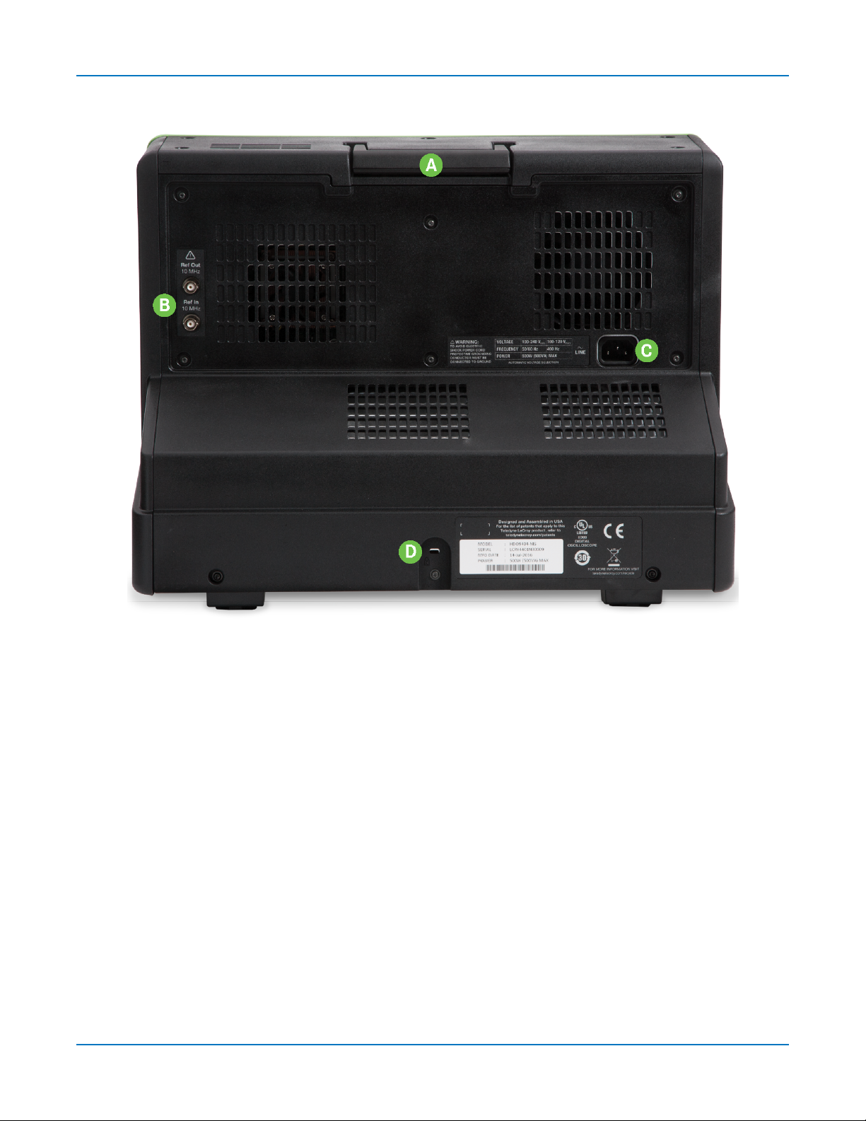
Back of Oscilloscope
A. Built-in carrying handle
B. Ref Out and Ref In for external reference clock
C. AC power inlet
D. Kensington lock
6
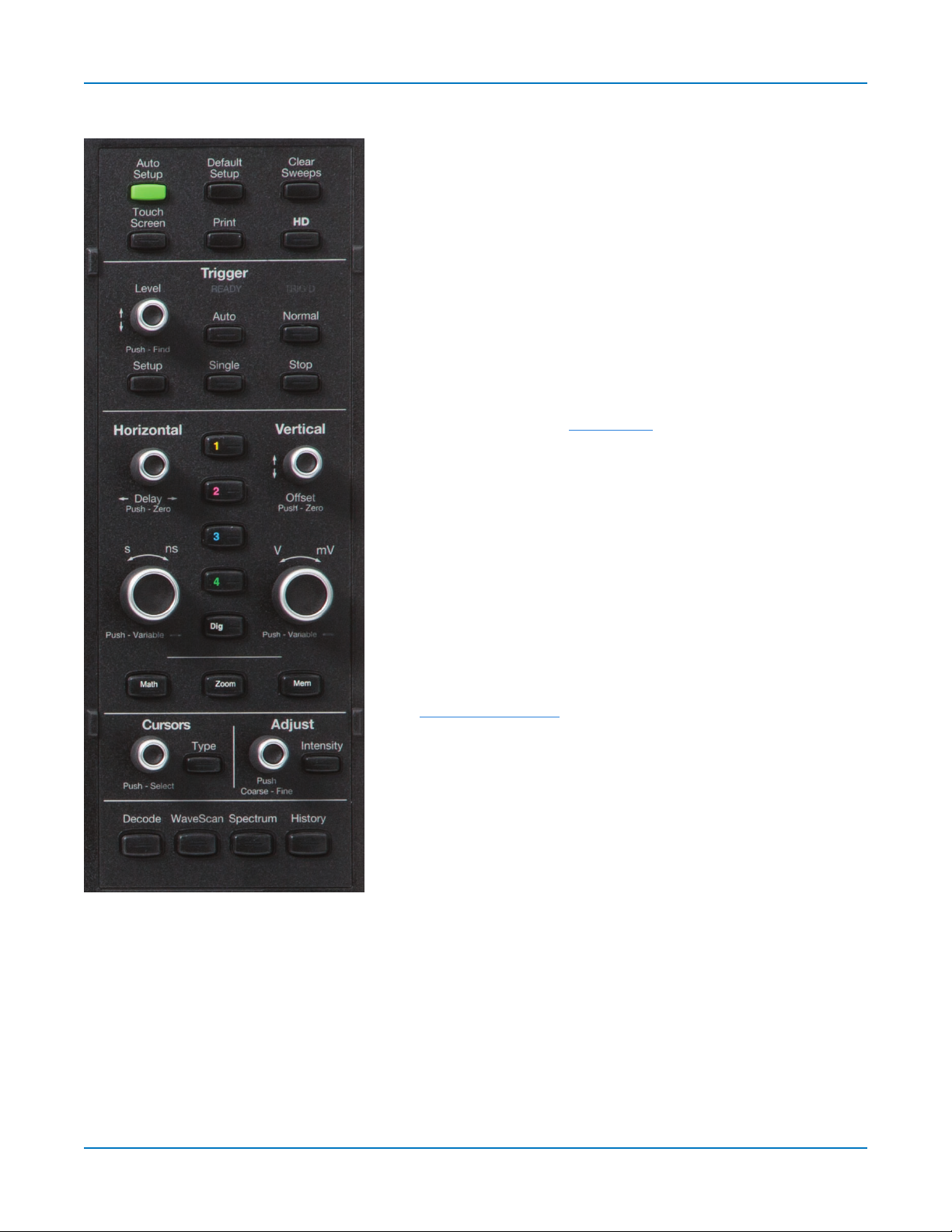
Front Panel
Oscilloscope Overview
Most front panel controls duplicate functionality also available
through the touch screen display.
All the knobs on the front panel function one way if turned and
another if pushed like a button. The first label describes the
knob’s principal “turn” action, and the second label describes
its “push” action.
Front panel buttons light up to indicate which traces and
functions are active. Actions performed from the front panel
always apply to the active trace.
Top Row Controls
Auto Setup performs an Auto Setup. After the first press, you
will be prompted for a confirmation. Press the button again or
use the touch screen to confirm.
Default Setup resets the oscilloscope to the factory default
configuration. After the first press, you will be prompted for a
confirmation. Press the button again or use the touch screen
to confirm.
Clear Sweeps resets the acquisition counter and any
cumulative measurements.
Touch Screen toggles on/off touch screen functionality.
Print captures the entire screen and outputs it according to
your Hardcopy settings.
HD turns on/off HD1024 technology.
Trigger Controls
The front panel Level knob changes the trigger threshold level
(V). The number is shown on the Trigger descriptor box.
Pushing the knob sets the trigger level to the 50% point of the
input signal.
Setup opens the Trigger setup dialog. Press it again to close the dialog.
The READY indicator is lit when the trigger is armed and ready. TRIG'D is lit momentarily when a
trigger occurs.
Auto sets Auto mode, which triggers the oscilloscope after a set time, even if the trigger conditions
are not met.
Normal sets Normal mode, which triggers the oscilloscope each time a signal is present that meets
the trigger conditions.
7

HDO9000 High Definition Oscilloscopes Operator's Manual
Single sets Single trigger mode. The first press readies the oscilloscope to trigger. The second press
arms and triggers the oscilloscope once (single-shot acquisition) when the input signal meets the
trigger conditions.
Stop prevents the scope from triggering on a signal. If you boot up the instrument with the trigger in
Stop mode, a "No trace available" message is shown. Press the Auto button to display a trace.
Horizontal Controls
Turn the Delay knob to change the Trigger Delay value (S). Push the knob to reset Delay to zero.
If the trace source is an input channel, turn the Horizontal Adjust knob to set the Time/division (S) of
the oscilloscope acquisition system. The value is shown on the Timebase descriptor box. When using
this control, the oscilloscope allocates memory as needed to maintain the highest sample rate
possible for the timebase setting. If the trace source is a zoom, memory or math function, turn the
knob to change the horizontal scale of the trace, effectively "zooming" in or out. The value is shown
on the corresponding descriptor box. Push the knob to change the setting in fine increments; push it
again to return to 1, 2, 5, 10-step increments.
Vertical Controls
The front panel Channel buttons (1-4) turn on a channel that is off, or activate a channel that is
already on. When the channel is active, pushing its channel button turns it off. A lit button shows the
active channel (in this image, C1 is lit).
Offset knob adjusts the zero level of the trace (this makes it appear to move up or down relative to
the center axis of the grid). The value appears on the trace descriptor box. Push it to reset Offset to
zero.
Gain knob sets Vertical Gain (V/div). The value appears on the trace descriptor box. Push it once to
adjust V/div in fine increments; push it again to adjust in 1, 2, 5, 10-step increments.
Dig button enables digital input on -MS models.
Math, Zoom, and Mem Buttons
The front panel Zoom button creates a quick zoom of each open channel trace. The resulting zoom
traces are 1/10 of the channel timebase and centered on the display. Touch the zoom trace
descriptor box to display the zoom controls and adjust this. Touch the Zoom button again to turn off
the zooms.
The Math and Mem(ory) buttons open the corresponding setup dialogs.
Cursor Controls
Cursors identify specific voltage and time values on the waveform. The white cursor markers help
make these points more visible, as well as provide a simple way to reposition them. A readout of the
values appears on the trace descriptor box.
There are five preset cursor types, each with a unique appearance on the display. These are
described in more detail in the Cursors section.
8

Oscilloscope Overview
Press the front panel Type button to apply or remove cursors. Continue pressing to cycle through all
cursor types until the desired type is found ("no cursors" will appear in the cycle).
Turn the Cursor knob to reposition the selected cursor line. Push it to select a different cursor line to
adjust.
Adjust & Intensity
The front panel Adjust knob changes the value in active (highlighted) data entry fields that do not
have dedicated knobs. Pushing Adjust toggles between coarse (large increment) or fine (small
increment) adjustments when the knob is turned.
The Intensity button sets the Adjust knob to control the trace intensity. When more data is available
than can actually be displayed, the Intensity button helps to visualize significant events by applying
an algorithm that dims less frequently occurring samples. This feature can also be accessed from
the Display Setup dialog.
Bottom Row Controls
Decode opens the Serial Decode dialog if you have serial data decoder options installed.
WaveScan opens the WaveScan dialog.
Spectrum opens the Spectrum Analyzer dialog if you have that option installed.
History opens the History Mode dialog.
9

HDO9000 High Definition Oscilloscopes Operator's Manual
Signal Interfaces
The instrument offers a variety of interfaces for using probes or other devices to input analog or
digital signals.
See the product page at teledynelecroy.com for a list of compatible devices.
Analog Inputs
A series of connectors arranged on the front of the instrument are used to input analog signals on
channels 1-4. EXT can be used to input an external trigger pulse or sample clock signal.
HDO9000 channel connectors use the ProBus interface. The ProBus interface contains a 6-pin power
and communication connection and a BNC signal connection to the probe. It includes sense rings for
detecting passive probes and accepts a BNC cable connected directly to it. ProBus offers 50 Ω and 1
MΩ input impedance and control for a wide range of probes.
The channel interfaces power probes and completely integrate the probe with the channel. Upon
connection, the probe type is recognized and some setup information, such as input coupling and
attenuation, is performed automatically. This information is displayed on the Probe Dialog, behind the
Channel (Cx) dialog. System (probe plus instrument) gain settings are automatically calculated and
displayed based on the probe attenuation.
Probes
The oscilloscope is compatible with the included passive probes and most Teledyne LeCroy active
probes that are rated for the instrument’s bandwidth. Probe specifications and documentation are
available at teledynelecroy.com/probes.
Passive Probes
The passive probes supplied are matched to the input impedance of the instrument but may need
further compensation. Follow the directions in the probe instruction manual to compensate the
frequency response of the probes.
Active Probes
Most active probes match probe to oscilloscope response automatically using probe response data
stored in an on-board EEPROM. This ensures the best possible combined probe plus oscilloscope
channel frequency response without the need to perform any de-embedding procedure.
Be aware that many active probes require a minimum oscilloscope firmware version to be fully
operational. See the probe documentation.
LBUS Interface
The LBUS (LeCroy Peripheral Bus) interface provides precise timing synchronization between the
oscilloscope and external devices. It can be used with the optional 8-CH-SYNC for synchronization
with other instruments or the HDA125-xx-LBUS for high-speed digital analysis and triggering.
10
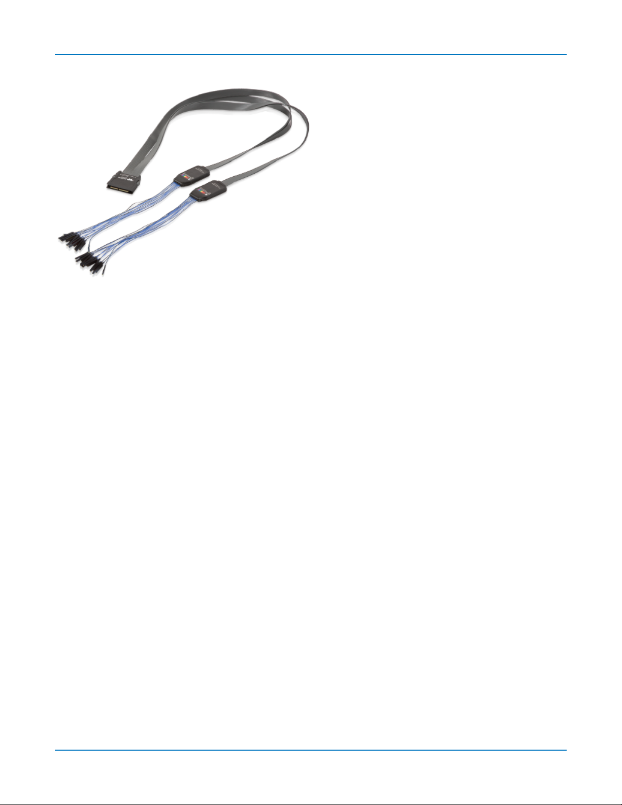
Digital Leadset
Connecting/Disconnecting the Leadset
Oscilloscope Overview
The digital leadset provided with -MS model
oscilloscopes enables input of up-to-16 lines of
digital data. Lines can be organized into four
logical groups and renamed appropriately.
The digital leadset features two digital banks
with separate Threshold controls, making it
possible to simultaneously view data from
different logic families.
The digital leadset connects to the Mixed Signal interface on the front of the instrument.
To connect the leadset to the instrument, push the connector into the Mixed Signal interface below
the front panel until you hear a click.
To remove the leadset, press and hold the buttons on each side of the connector, then pull out to
release.
Grounding Leads
Each flying lead has a signal and a ground connection. A variety of ground extenders and flying ground
leads are available for different probing needs.
To achieve optimal signal integrity, connect the ground at the tip of the flying lead for each input used
in your measurements. Use either the provided ground extenders or ground flying leads to make the
ground connection.
11
HDO9000 High Definition Oscilloscopes Operator's Manual
Oscilloscope Set Up
Powering On/Off
Press the Power button to turn on the instrument. The X-Stream application loads automatically
when you use the Power button.
Caution: Do not change the instrument’s Windows®Power Options setting from the default
Never to System Standby or System Hibernate. Doing so can cause the system to fail.
Caution: Do not power on or calibrate with a signal attached.
Use the File > Shutdown menu bar option to switch "off". Pressing Power again will execute a
shutdown, but we do not recommend doing this because it does not allow the Windows operating
system to shut down properly, and memories and setup panels will not be saved. Never power off by
pulling the power cord from the socket or shutting off a connected power strip.
The Power button does not disconnect the instrument from the AC power supply. The only way to fully
power down the instrument is to unplug the AC power cord.
We recommend unplugging the instrument if it will remain unused for a long period of time.
Software Activation
The operating software (firmware and standard applications) is active upon delivery. At power-up, the
instrument loads the software automatically.
Firmware
Free firmware updates are available periodically from the Teledyne LeCroy website at:
teledynelecroy.com/support/softwaredownload
Registered users can receive an email notification when a new update is released. Follow the
instructions on the website to download and install the software.
Purchased Options
If you decide to purchase an option, you will receive a license key via email that activates the optional
features. See Options for instructions on activating optional software packages.
12

Oscilloscope Set Up
Connecting to Other Devices/Systems
Make all desired cable connections. After start up, configure the connections using the menu options
listed below. More detailed instructions are provided later in this manual.
LAN
The instrument accepts DHCP network addressing. Connect a cable from the Ethernet port on the
side panel to a network access device.
To assign a static IP address, go to Utilities > Utilities Setup > Remote and choose Net Connections
from the Remote dialog. Use the standard Windows networking dialogs to configure the device
address.
Go to Utilities > Preference Setup > Email to configure email settings.
USB Peripherals
Connect the device to a USB port on the front or side of the instrument.
Printer
The HDO9000 supports USB printers compatible with the instrument's Windows OS. Go to Utilities >
Utilities Setup > Hardcopy to configure printer settings.
External Monitor
You may operate the instrument using the built-in touch screen or attach an external monitor for
extended desktop operation. A properly configured external touch-screen monitor will take on all the
touch-screen capabilities of the internal display.
Note: The oscilloscope display utilizes Fujitsu touch-screen drivers. Because of conflicts,
external monitors with Fujitsu drivers can not be used to control the system, only as displays.
The HDO9000 supports WQXGA monitors with 2560x1600 resolution.
Connect the monitor cable to the DisplayPort connector on the side of the instrument (you can use an
adaptor if the monitor cable has a different interface). Monitors with DVI-D interfaces are also
supported. Minimize the X-Stream application and use the Windows controls to configure the display.
Configure the instrument as the primary monitor and be sure to extend, not duplicate, the display.
Remote Control
Go to Utilities > Preference Setup > Remote to configure remote control. Connect the devices using
the cable type required by your selection. TCP/IP over Ethernet is generally supported, as is USB over
the USBTMC connection. GPIB is also supported with the correct hardware option installed.
13
HDO9000 High Definition Oscilloscopes Operator's Manual
Auxilliary Output
To output signal from the instrument to another device, connect a BNC cable from Aux Out to the
other device. Go to Utilities > Utilities Setup > Aux Output to configure the output.
Language Selection
To change the language that appears on the touch screen:
1. Go to Utilities > Preference Setup > Preferences and make a Language selection.
2. Follow the prompt to restart the application.
To also change the language of the Windows operating system dialogs:
1. Choose File > Minimize to hide X-Stream and show the Windows Desktop.
2. From the Windows task bar, choose Start > Control Panel > Clock, Language and Region.
3. Under Region and Language select Change Display Language.
4. Touch the Install/Uninstall Languages button.
5. Select Install Language and Browse Computer or Network.
6. Touch the Browse button, navigate to D:\Lang Packs\ and select the language you want to
install. The available languages are: German, Spanish, French, Italian, and Japanese. Follow
the installer prompts.
7. Reboot after changing the language.
Note: Other language packs are available from Microsoft’s website.
14

Using MAUI
Using MAUI
MAUI, the Most Advanced User Interface, is Teledyne LeCroy's unique oscilloscope user interface.
MAUIis designed for touch—all important controls for vertical, horizontal, and trigger are only one
touch away.
Touch Screen
The touch screen is the principal viewing and control center. The entire display area is active: use
your finger or a stylus to touch, drag, swipe, or draw a selection box.
Many controls that display information also work as “buttons” to access other functions. If you have a
mouse installed, you can click anywhere you can touch to activate a control; in fact, you can alternate
between clicking and touching, whichever is convenient for you.
The touch screen is divided into the following major control groups:
l Menu bar
l Grid area
l Descriptor boxes
l Dialogs
Menu Bar
The top of the window contains a complete menu of functions. Making a selection here changes the
dialogs displayed at the bottom of the screen.
15
HDO9000 High Definition Oscilloscopes Operator's Manual
While many common operations can also be performed from the front panel or launched via the
descriptor boxes, the menu bar is the best way to access dialogs for Save/Recall (File) functions,
Display functions, Status, LabNotebook, Pass/Fail setup, and Utilities/Preferences setup.
You will see a Q-Scape control added to the menu bar when the Q-Scape option is
installed. This allows you to choose different tabbed display configurations. See Display.
If an action can be “undone”, a small Undo button appears at the far right of the menu bar. Click this
to return to the previous display.
Grid Area
The grid area displays the waveform traces. Every grid is 8 Vertical divisions representing the full
number of Vertical levels possible at the current resolution and 10 Horizontal divisions. The value
represented by Vertical and Horizontal divisions depends on the Vertical and Horizontal scale of the
traces that appear on the grid.
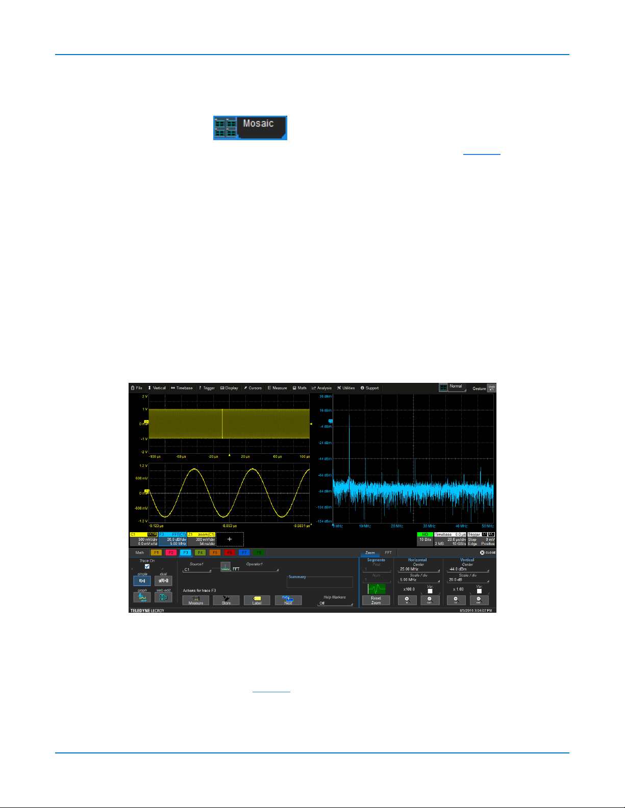
Multi-Grid Display
The grid area can be divided into multiple grids showing different types and numbers of traces (by
default, it will divide automatically as needed up to 16 times). Regardless of the number and
orientation of grids, every grid always represents the same number of Vertical levels. Therefore,
absolute Vertical measurement precision is maintained.
Different types of traces opening in a multi-grid display.
Q-Scape Tabs
On instruments with the Q-Scape option installed, Tabs 1-4 appear along the top of the grid area. Each
tab is a distinct multi-grid display. See Display for more information about using Q-Scape.
16
Using MAUI
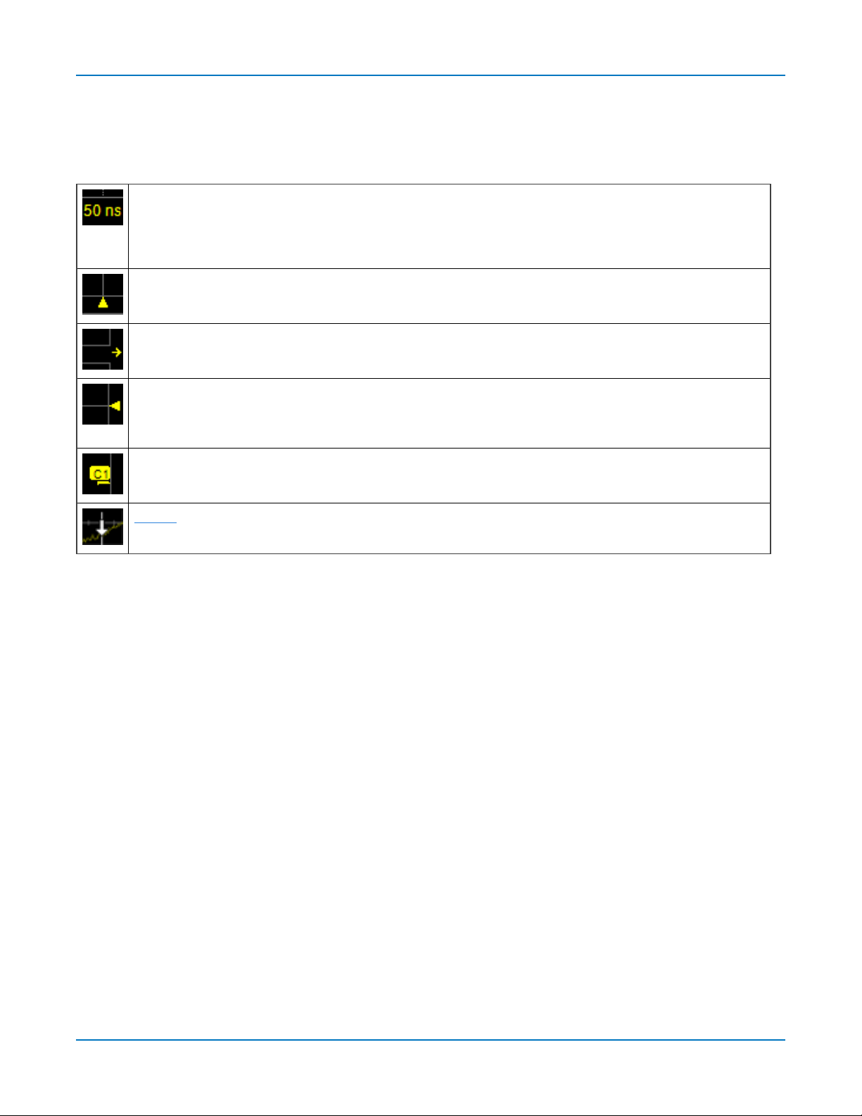
Grid Indicators
These indicators appear around or on the grid to mark important points on the display. They are
matched to the color of the trace to which they apply. When multiple traces appear on the same grid,
indicators refer to the foreground trace—the one that appears on top of the others.
Axis labels
or change the Vertical/Horizontal scale. Originally shown in absolute values, the labels change to show delta
from 0 (center) when the number of significant digits grows too large. The number of labels that appear on
each grid depends on the total number of grids open. To remove them, go to Display > Display Setup and
deselect Axis Labels.
Trigger Time
Unless Horizontal Delay is set, this indicator is at the zero (center) point of the grid. Delay time is shown at the
top right of the Timebase descriptor box.
Pre/Post-trigger Delay
Delay has shifted the Trigger Position indicator to a point in time not displayed on the grid. All Delay values are
shown on the Timebase Descriptor Box.
Trigger Level
in Stop trigger mode, or in Normal or Single mode without a valid trigger, a hollow triangle of the same color
appears at the new trigger level. The trigger level indicator is not shown if the triggering channel is not displayed.
Zero Volts Level
the number and color of the trace.
Cursor markers
drop cursor markers to quickly reposition them.
Grid Intensity
mark the times/units represented by a grid division. They update dynamically as you pan the trace
, a small triangle along the bottom (horizontal) edge of the grid, shows the time of the trigger.
, a small arrow to the bottom left or right of the grid, indicates that a pre- or post-trigger
at the right edge of the grid tracks the trigger voltage level. If you change the trigger level when
is located at the left edge of the grid. One appears for each open trace on the grid, sharing
appear over the grid to indicate specific voltage and time values on the waveform. Drag-and-
You can adjust the brightness of the grid lines by going to Display > Display Setup and entering a new
Grid Intensity percentage. The higher the number, the brighter and bolder the grid lines.
Descriptor Boxes
Trace descriptor boxes appear just beneath the grid whenever a trace is turned on. They function to:
l Inform—descriptors summarize the current trace settings and its activity status.
l Navigate—touch the descriptor box once to activate the trace, a second time to open the trace
setup dialog.
l Arrange—drag-and-drop descriptor boxes to move traces among grids.
l Configure—drag-and-drop descriptor boxes to change source or copy setups.
Besides trace descriptor boxes, there are also HD, Timebase and Trigger descriptor boxes
summarizing the acquisition settings shared by all channels, which also open the corresponding
setup dialogs.
17
HDO9000 High Definition Oscilloscopes Operator's Manual
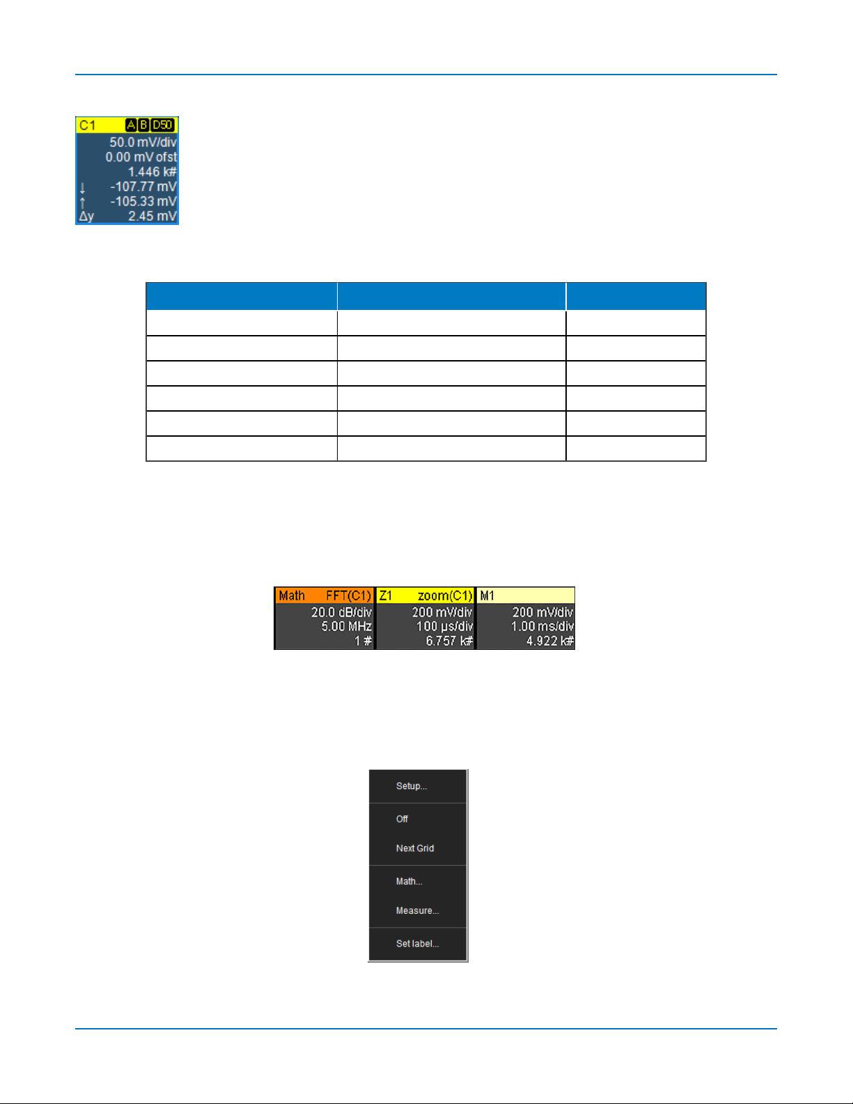
Channel Descriptor Box
Channel trace descriptor boxes correspond to analog signal inputs. They show
(clockwise from top left): Channel Number, Pre-processing list, Coupling, Vertical
Scale (gain) setting, Vertical Offset setting, Sweeps Count (when averaging),
Vertical Cursor positions, and Number of Segments (when in Sequence mode).
Codes are used to indicate pre-processing that has been applied to the input. The
short form is used when several processes are in effect.
Pre-processing Symbols on Descriptor Boxes
Pre-Processing Type Long Form Short Form
Sin X Interpolation SINX S
Averaging AVG A
Inversion INV I
Deskew DSQ DQ
Coupling DC50
Bandwidth Limiting BWL B
, DC1M, AC1M
or GND D50
, D1, A1
or G
Other Trace Descriptor Boxes
Similar descriptor boxes appear for math (Fx), zoom (Zx), and memory (Mx) traces. These descriptor
boxes show any Horizontal scaling that differs from the signal timebase. Units will be automatically
adjusted for the type of trace.
Trace Context Menu
Touch and hold ("right-click") on the trace descriptor box until a white circle appears to open the trace
context menu, a pop-up menu of actions to apply to the trace such as turn off, move to next grid or
label.
18
Using MAUI
HD Descriptor Box
The HD descriptor box summarizes the total resolution at which the instrument is operating. When
HD1024 is enabled, this may be 9 or 10 bits depending on the number of active channels and other
timebase settings. Touch the HD descriptor to open the HD Summary dialog, which shows the current
resolution, bandwidth, and other settings per channel. When HD1024 is disabled, the HD descriptor
box is hidden.
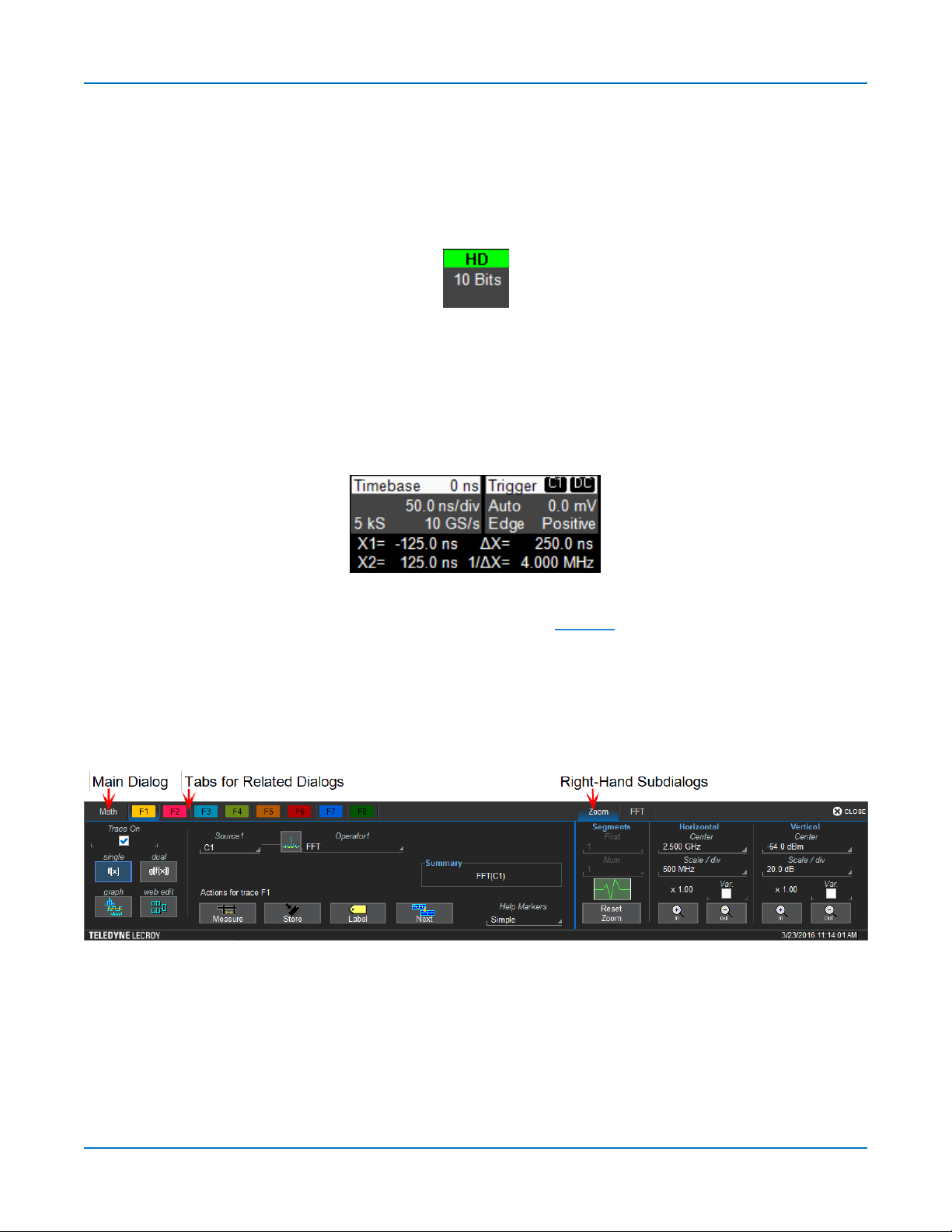
Timebase and Trigger Descriptor Boxes
The Timebase descriptor box shows: (clockwise from top right) Horizontal Delay, Time/div, Sample
Rate, Number of Samples, and Sampling Mode (blank when in real-time mode).
Trigger descriptor box shows: (clockwise from top right) Trigger Source and Coupling, Trigger Level
(V), Slope, Trigger Type, Trigger Mode.
Horizontal (time) cursor readout, including the time between cursors and the frequency, is shown
beneath the TimeBase and Trigger descriptor boxes. See the Cursors section for more information.
Dialogs
Dialogs appear at the bottom of the display for entering setup data. The top dialog will be the main
entry point for the selected functionality. For convenience, related dialogs appear as a series of tabs
behind the main dialog. Touch the tab to open the dialog.
19
HDO9000 High Definition Oscilloscopes Operator's Manual
Right-Hand Subdialogs
At times, your selections will require more settings than can fit on one dialog, or the task commonly
invites further action, such as zooming a new trace. In that case, subdialogs will appear to the right of
the dialog. These subdialog settings always apply to the object that is being configured on the lefthand dialog.
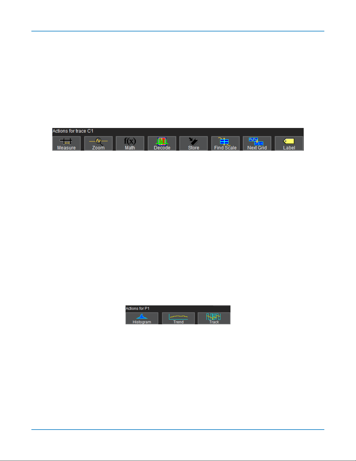
Action Toolbar
Several setup dialogs contain a toolbar at the bottom of the dialog. These buttons enable you to
perform commonplace tasks—such as turning on a measurement—without having to leave the
underlying dialog. Toolbar actions always apply to the active trace.
Measure opens the Measure pop-up to set measurement parameters on the active trace.
Zoom creates a zoom trace of the active trace.
Math opens the Math pop-up to apply math functions to the active trace and create a new math trace.
Decode opens the main Serial Decode dialog where you configure and apply serial data decoders and
triggers. This button is only active if you have serial data software options installed.
Store loads the active trace into the corresponding memory location (C1, F1 and Z1 to M1; C2, F2 and
Z2 to M2, etc.).
Find Scale performs a vertical scaling that fits the waveform into the grid.
Next Grid moves the active trace to the next grid. If you have only one grid displayed, a new grid will
be created automatically, and the trace moved.
Label opens the Label pop-up to annotate the active trace.
Histogram, Trend, and Track buttons appear at the bottom of the Parameter (Px) dialogs. They allow
you to create a Math function to plot the parameter while remaining on the measurement dialogs.
20
 Loading...