

Teledyne HDO8000A Getting Started Manual
HDO8000A
High Denition Oscilloscopes
Getting Started Guide


700 Chestnut Ridge Road
Chestnut Ridge, NY 10977
1.800.5.LECROY
•
teledynelecroy.com
© 2017 Teledyne LeCroy, Inc. All rights reserved.
Unauthorized duplication of Teledyne LeCroy documentation materials other than for internal sales
and distribution purposes is strictly prohibited. However, clients are encouraged to duplicate and
distribute Teledyne LeCroy documentation for internal educational purposes.
HDO and Teledyne LeCroy are trademarks of Teledyne LeCroy, Inc. Windows is a registered
trademark of Microsoft Corporation. Other product or brand names are trademarks or requested
trademarks of their respective holders. Information in this publication supersedes all earlier
versions. Specifications are subject to change without notice.
928574-00 Rev A
June, 2017
HDO8000A
Getting Started Guide

Welcome
Thank you for buying a Teledyne LeCroy product. We’re certain you’ll be pleased with the detailed features unique to our instruments.
This Getting Started Guide is designed to cover important safety and installation information for your oscilloscope, along with some basic operating
procedures so you’re quickly working with waveforms.
Introduction
About the HDO8000A Oscilloscopes 2
Specifications 3
Materials List 3
General Safety Information 4
Support 6
Set Up
The Front of Your Oscilloscope 8
The Side of Your Oscilloscope 10
Connecting to External Devices/Systems 11
The Back of Your Oscilloscope 12
Powering On/Off 13
Language Selection 13
Software Activation 14
Firmware Update 14
User Interface
Touch Screen Display 16
Changing the Display 18
Working With Traces 20
MAUI with OneTouch 21
Front Panel 26
Contents
Basics
Vertical 28
Horizontal (Timebase) 30
Triggers 31
Cursors 32
Measurements & Statistics 33
Math 34
Memories (Reference Waveforms) 35
Decode 36
WaveScan 37
Spectrum Analyzer 38
History Mode 39
Q-Scape Multi-Tab Dispay 40
Saving and Sharing Data 41
Software Options 42
Reference
Service 44
Certifications 45
Warranty 47
Intellectual Property 47
Windows License Agreement 47

HDO8000A
High Denition Oscilloscopes
INTRODUCTION

INTRODUCTION
2
About the HDO8000A Oscilloscopes
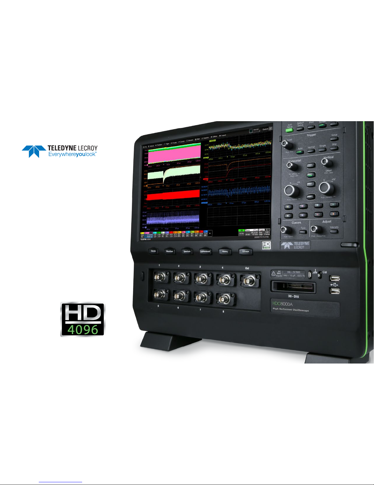
HDO8000A High Definition Oscilloscopes have more channels, more
resolution, more bandwidth and more memory than any other midrange
oscilloscope. They are ideal for debugging and troubleshooting high power
or three-phase power electronics, automotive electronics, and embedded/
mechatronic designs with high resolution sensor signals. Comprehensive
digital logic (MSO), low-speed serial data trigger, decode and analysis
toolsets, and the widest variety of probes and application packages
complete the solution. Get the most intuitive long-memory analysis using
the unique Q-Scape™ multi-tab display architecture.
HD4096
HD4096 high-definition technology consists of high sample rate 12-bit
ADCs, high signal-to-noise input amplifiers, and a low-noise system
architecture. This technology enables HDO™ oscilloscopes to capture and
display signals up to 1 GHz with a high sample rate and 16 times more
resolution than other oscilloscopes. Waveforms captured and displayed
on the HDO8000A with HD4096 technology are cleaner and crisper. Signal
details often lost in the noise are clearly visible and easy to distinguish,
and measurements can be performed with unmatched precision for
improved debug and analysis.
Enhanced Sample Rate
Enhanced sample rate technology automatically ensures optimal display
of acquired waveforms to the instrument’s full rated bandwidth.
Q-Scape Multi-Tab Display Architecture
Unique Q-Scape multi-tab display architecture speeds your understanding
of your design by providing four times the display area. Quickly move
waveforms to different tabs through drag-and-drop. Extended desktop
supports UHD 3840 x 2160 pixel displays.
MAUI with OneTouch
MAUI with OneTouch introduces a new paradigm for oscilloscope user
experience. Dramatically reduce setup time with revolutionary dragand-drop actions to copy and setup channels, math functions and
measurement parameters without lifting a finger. Use common gestures
like pinch, swipe and flick to intuitively interact with the oscilloscope.
Quickly enable a new trace or parameter using the “Add New” button, and
turn off any trace or parameter with a simple flick of the finger.
Mixed Signal Option
With embedded systems growing increasingly more complex,
powerful mixed signal debug capabilities are an essential part of
modern oscilloscopes. The 16 integrated digital channels and set of tools
designed to view, measure and analyze analog and digital signals enable
fast debugging of mixed signal designs. Flexible analog and digital
cross-pattern triggering across all 24 channels provides the ability to
quickly identify and isolate problems in an embedded system.
Comprehensive Analysis Tools
HDO8000A has one of the most comprehensive trigger, decode, math,
measurement and application toolsets available. Use tracks, trends and
histograms to enhance understanding of complex behaviors. Navigate
waveforms in the frequency domain using Spectrum Analyzer type
controls. WaveScan® Search and Find allows you to search a single
acquisition using more than 20 different criteria. History Mode lets you
scroll back in time to view previous acquisitions and isolate anomalies.
New LabNotebook Report Generator
LabNotebook stores the exact state of your oscilloscope in a composite
file format that can later be recalled and reviewed, annotated with custom
markup, or output to a preformatted report—right on the instrument.

INTRODUCTION
3
Specications
Detailed specifications are maintained in the Datasheet on the product
page at teledynelecroy.com.
Key Specications
Bandwidth 350 MHz–1 GHz
Resolution 12-bit
Analog Channels 8
Sample Rate up to 10 GS/s *
Memory (per channel) 50 Mpts/ch
Optional Memory (per channel) 250 Mpts/ch
Digital Channels 16
Digital Sample Rate 1.25 GS/s
Min. Detectable Pulse Width 2 ns
Max. Input Frequency 250 MHz
* With Enhanced Sample Rate
Materials List
Check that you have all the parts listed here. Contact Teledyne
LeCroy immediately if any part is missing.
•
1 oscilloscope
•
4 passive probes
•
1 AC power cord (rated for country)
•
1 protective front cover
•
1 Getting Started Guide
•
1 Oscilloscope Security Certificate
•
1 Oscilloscope Registration Card
•
1 Calibration Document
HDO8KA-MSO option includes:
•
1 digital leadset
•
5 flying ground leads
•
20 ground extenders
•
22 XL microgrippers
•
enabling keycode (installed on oscilloscope)
INTRODUCTION
4
General Safety Information
This section contains instructions that must be observed to keep the
instrument operating in a correct and safe condition. You are required to
follow generally accepted safety procedures in addition to the precautions
specified in this section. The overall safety of any system incorporating
this instrument is the responsibility of the assembler of the system.
Symbols
These symbols appear on the instrument’s front or rear panels and in its
documentation to alert you to important safety considerations.
CAUTION of damage to instrument, or WARNING of hazard to
health. Attend to the accompanying information to protect against
personal injury or damage. Do not proceed until conditions are fully
understood and met.
WARNING. Risk of electric shock.
Measurement ground connection.
Alternating Current.
On/Standby power.
Precautions
• Use proper power cord. Use only the power cord shipped with this
instrument and certified for the country of use.
• Maintain ground. This product is grounded through the power cord
grounding conductor. To avoid electric shock, connect only to a
grounded mating outlet.
• Connect and disconnect properly. Do not connect/disconnect probes
or test leads while they are connected to a voltage source.
• Observe all terminal ratings. Do not apply a voltage to any input
(C1-C8, EXT, AUX, or D0-D15) that exceeds the maximum rating of that
input. Refer to the body of the oscilloscope for maximum input ratings.
• Use only within operational environment listed. Do not use in wet or
explosive atmospheres.
• Use indoors only.
• Keep product surfaces clean and dry.
• Exercise care when lifting and carrying. Always use the built-in
carrying handle.
• Do not block the cooling vents. Leave a minimum six-inch gap
between the instrument and the nearest object. Keep the underside
clear of papers and other objects.
• Do not remove the covers or inside parts. Refer all maintenance to
qualified service personnel.
• Do not operate with suspected failures. Inspect all parts regularly
and do not use the product if any part is damaged. Cease operation
immediately and sequester the instrument from inadvertent use.

INTRODUCTION
5
Operational Environment
Temperature: 5° to 40° C
Humidity: Maximum relative humidity 90% for temperatures up to
31° C decreasing linearly to 50% relative humidity at 40° C
Altitudes: up to 3,000 m (at < 30° C)
Power and Grounding
The instrument operates from a single-phase, 100 to 240 Vrms (± 10%)
AC power source at 50/60 Hz (± 5%) or a 100 to 120 Vrms (± 10%) AC
power source at 400 Hz (± 5%). The instrument automatically adapts to
the line voltage. Manual voltage selection is not required.
The AC inlet ground is connected directly to the frame of the instrument.
For adequate protection against electric shock, connect to a mating outlet
with a safety ground contact.
WARNING. Interrupting the protective conductor inside or outside
the oscilloscope, or disconnecting the safety ground terminal,
creates a hazardous situation. Intentional interruption is prohibited.
Maximum power consumption with all accessories installed (e.g., active
probes, USB peripherals, digital leadset) is 550 W (550 VA)
Power consumption in Standby mode is 10 W.
Cleaning
Clean only the exterior of the oscilloscope using a damp, soft cloth. Do
not use harsh chemicals or abrasive elements. Under no circumstances
submerge the instrument or allow moisture to penetrate it. Avoid electric
shock by unplugging the power cord from the AC outlet before cleaning.
CAUTION. Do not attempt to clean internal parts.
Calibration
The HDO8000A is calibrated at the factory prior to being shipped. This
calibration is run at 23° C (± 2° C) and is valid for temperatures ± 5° C of
the original calibration temperature. Within this temperature range, the
HDO8000A will meet all specifications.
Warm up the HDO8000A for at least 20 minutes prior to use. During the
warm-up period, the oscilloscope will automatically initiate calibrations to
ensure that it is always calibrated.
When the oscilloscope is used outside of the factory calibration
temperature range, a user-invoked temperature dependent calibration is
recommended. There are two options for this calibration: Calibrate All or
Calibrate Current Setting.
Calibrate All - All possible combinations of vertical and horizontal settings
are calibrated at the current temperature. This calibration is valid for the
current temperature ± 5° C and takes about 50 minutes.
Calibrate Current Setting - The oscilloscope is calibrated at the current
vertical and horizontal settings. This calibration is valid for these settings
at the current temperature ± 5° C and takes under 30 seconds.
It is also recommended that the HDO8000A be calibrated when it has
been more than 1 month since the previous calibration.
CAUTION. Remove all inputs from the oscilloscope prior to
calibration.

INTRODUCTION
6
Support
Online Documentation
Online Help is available by selecting Support > Dynamic Help from the
oscilloscope display menu bar. You can also select Support > OneTouch
Help for a demonstration of MAUI with OneTouch.
Teledyne LeCroy publishes a free Technical Library on its website at
teledynelecroy.com/support/techlib. Manuals, tutorials, application
notes, white papers, and videos are available to help you get the most out
of your Teledyne LeCroy products.
The HDO8000A/MDA800A Oscilloscopes Operator’s Manual can be
downloaded from teledynelecroy.com/web/hdo8000-manual. This
PDF document contains more extensive procedures for operating your
oscilloscope than are found here.
The Datasheet published on the product page contains the detailed
product specifications.
Technical Support
Registered users can contact their local Teledyne LeCroy service center to
make Technical Support requests by phone or email. For a complete list
of offices, visit teledynelecroy.com/support/contact.
You can also submit Technical Support requests via the website at
teledynelecroy.com/support/techhelp.

SET UP
HDO8000A
High Denition Oscilloscopes
SET UP
8
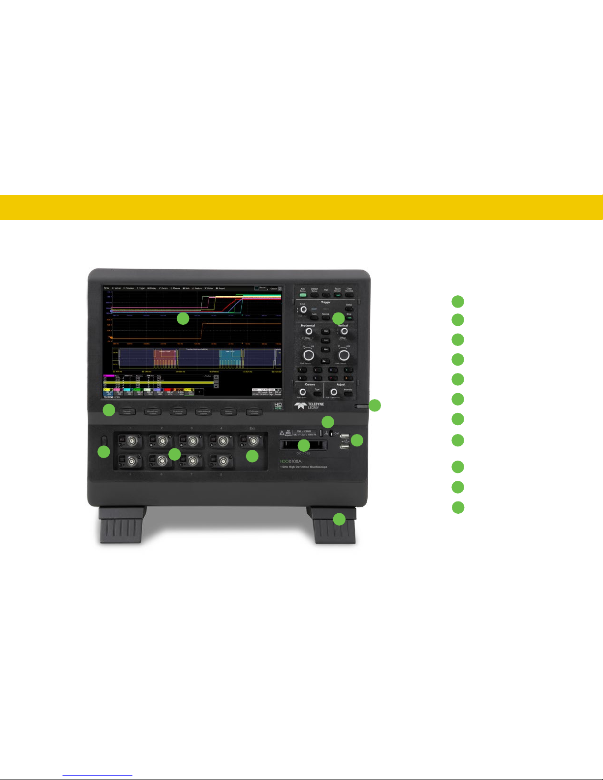
The Front of Your Oscilloscope
Touch Screen Display
Front Panel
Shortcut Buttons
Built-in Stylus Holder
Power Button
Channel Inputs
EXT Input
Mixed Signal Interface
Ground and Calibration
Output Terminals
USB Ports
Tilting Feet
A
B
C
D
E
F
G
H
I
J
K
A
B
C
D
E
G
H
I
F
J
K
SET UP
9
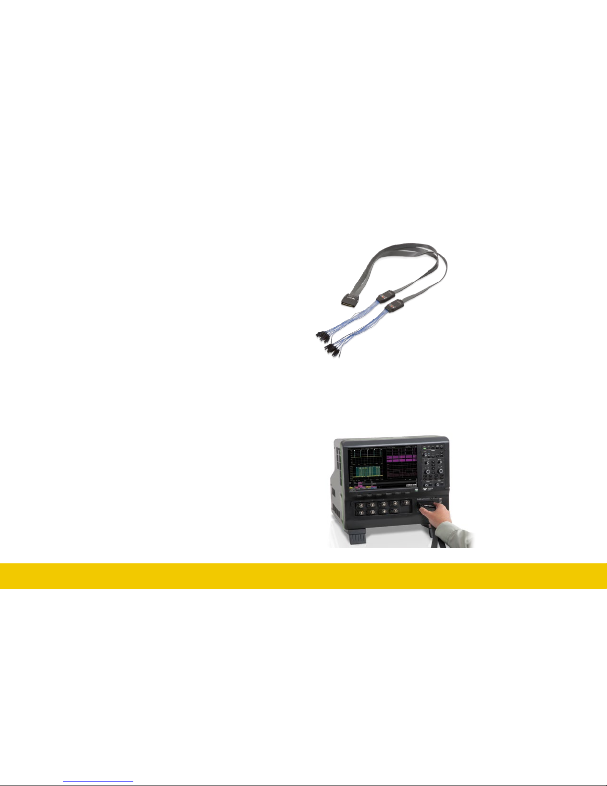
Each flying lead has a signal
and a ground connection. A
variety of ground extenders
and flying ground leads are
available for different probing
needs. To achieve optimal
signal integrity, connect the
ground at the tip of the flying
lead for each channel used in
measurements. Use either the
provided ground extenders or
ground flying leads to make
the ground connection.
To connect the leadset to the oscilloscope, push the connector into the
mixed signal interface until you hear a click.
To remove the leadset, press in and hold the buttons on each side of the
connector, then pull out to release it.
The touch screen display is the principal viewing and control center of
the oscilloscope. See “Touch Screen Display” on p.16 for an overview of
its components and capabilities.
The front panel houses buttons and knobs that control different
oscilloscope settings. Operate the instrument using front panel hard
controls, display soft controls, or the mix of both that is convenient for
you. See “Front Panel” on p.26 for more information.
Immediately beneath the touch screen is a row of shortcut buttons that
launch various oscilloscope functions, such as LabNotebook, Spectrum
Analyzer, or serial data trigger and decode software.
The built-in stylus holder stores a stylus that can be used with the touch
screen display.
The power button turns on the oscilloscope. See “Powering On/Off” for
more information about shutting down.
Channels 1–8 are signal inputs to the oscilloscope; Ext is for inputting an
external trigger or external sample clock.
Ground and calibration output terminals are used to compensate
passive probes. HDO8000A oscilloscopes are compatible with the
included passive probes and all Teledyne LeCroy ProBus active probes
that are rated for the oscilloscope’s bandwidth. Probe specifications and
documentation are available at teledynelecroy.com/probes.
Supplied with the Mixed Signal option (HDO8K-MSO), the digital leadset
connects to the mixed signal interface to input of up-to-16 lines of digital
data. Two digital banks with separate threshold and hysteresis controls
make it possible to simultaneously view data from different logic families.
SET UP
10
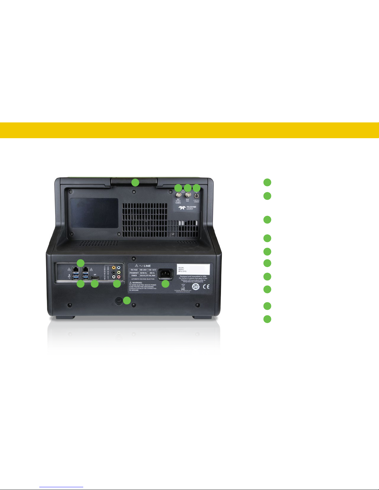
The Back of Your Oscilloscope
A
B
C
D
F
G
H
I
J
E
A
B C D
E
Built-in Carrying Handle
Ref In/Out connector to input/output
an external Reference Clock
Aux Out connector to send device
trigger enabled, trigger out, or pass/
fail output to another device
USBTMC Port for remote control
Ethernet Ports (2) for LAN connection
Host USB 3.0 Ports (4)
Display Port for external monitor
Audio In/Out: Speaker, Mic, and
Line-In for external audio devices
AC Power Inlet for the AC line cord
Kensington Lock
G H
I
F
J

SET UP
11
Connecting
See the HDO8000A Oscilloscopes Operator’s Manual for more instructions
on connecting to external devices.
LAN
HDO8000A accepts DHCP network addressing. Connect a cable from
either Ethernet port on the back panel to a network access device. Go to
Utilities > Utilities Setup > Remote to find the IP address.
To assign the oscilloscope a static IP address, open Net Connections
from the Remote dialog and use the Windows networking dialogs to
configure the device address. Go to File > File Sharing to configure email.
Printer
HDO8000A supports USB printers that are compatible with the Windows
OS installed on the oscilloscope. Connect the printer to any host USB port,
then go to File > Print and select Printer to configure settings. Choose
Properties to open the Windows print dialog.
Audio/USB Peripherals
Connect the device to the appropriate port. These connections are “plugand-play”. Use the Windows control panel to make adjustments. Choose
File > Minimize to go to the Windows desktop.
Remote Control
Connect from either the LAN port (for TCP/IP and LXI) or the USBTMC
port on the back. Go to Utilities > Utilities Setup > Remote to configure
remote control.
External Monitor
HDO8000A supports up to UHD monitors with 3840x2160 resolution.
Connect the monitor cable to the Display Port output on the back of the
instrument (you can use a convertor if the cable has a different interface).
Go to Display > Display Setup > Open Monitor Control Panel to configure
display settings using the Windows control panel dialogs. Be sure to
configure the oscilloscope as the primary display.
To use the Extend Grids feature, configure the second monitor to extend,
not duplicate, the oscilloscope display. If the external monitor is touch
screen enabled, the MAUI user interface can be controlled from the
external monitor.
Note: The oscilloscope touch screen uses Fujitsu drivers. Because of
potential conflicts, external monitors with Fujitsu drivers cannot be used
as touch screens, only as displays.
External Sample Clock
To input an external sample clock, connect a BNC cable from EXT on
the front of the instrument to the clock source device. Go to Timebase >
Horizontal Setup > Clock Source to configure the clock.
Reference Clock
To input or output a reference clock, connect a BNC cable from Ref In/Out
on the back of the instrument to the other instrument. Go to Timebase >
Horizontal Setup > Clock Source to configure the clock.
Auxiliary Output
Connect a BNC cable from Aux Out on the back of the instrument to the
other device. Go to Utilities > Utilities Setup > Aux Output to configure
the output signal.
SET UP
12
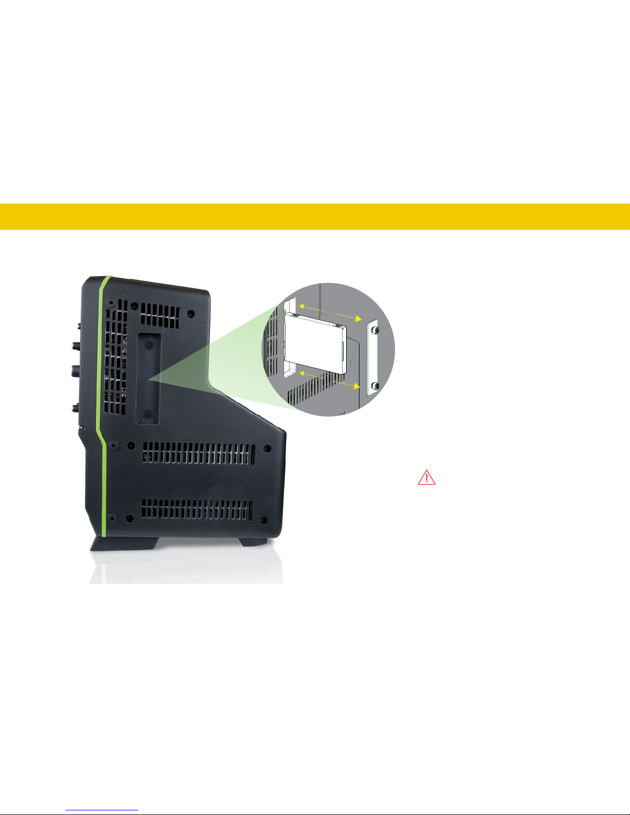
The Side of Your Oscilloscope
The side of the HDO8000A houses a removable
hard drive.
To remove the drive:
1. Loosen the two knobs that secure the
cover and remove it. You may use a
screwdriver to loosen the knobs.
2. Grab the drive by the attached tab and
pull out.
To replace the drive:
1. Insert the drive with the label facing away
from you. Do not force the drive into place.
Strong resistance may mean the drive is
flipped the wrong way.
2. Replace the cover.
Power down the oscilloscope before
removing or replacing the drive. Failure to
do so may damage the instrument.
Secure the cover at all times when the
drive is in place.
SET UP
13
Powering On/Off
Connect the line cord rated for your country to the AC power inlet on the
back of the instrument, then plug it into a grounded AC power outlet.
(see Power and Grounding on p.5).
Press the Power button on the front to switch on the instrument.
CAUTION. Do not change the instrument’s Windows® Power
Options from the default Never to System Standby or System
Hibernate modes.
CAUTION. Do not power on or calibrate the oscilloscope with a
signal attached.
The safest way to power off is to use the File > Shutdown menu bar option.
Briefly pressing the Power button again will power off, but holding will
execute a hard shutdown, and we do not recommend doing this as it
does not allow the Windows operating system to shut down properly, and
memories and setup panels will not be saved.
The Power button and File > Shutdown do not disconnect the
oscilloscope from the AC power supply; some “housekeeping” circuitry
continues to draw power. The only way to fully power down the
instrument is unplug the AC line cord from the outlet.
CAUTION. Do not place the instrument so that it is difficult to
reach the power cord in case you need to quickly disconnect from
AC power.
We recommend unplugging the instrument if it will remain unused for a
long period of time.
Language Selection
To change the language that appears on the display, go to Utilities >
Preference Setup > Preferences and make your Language selection.
Restart the oscilloscope software after the language is selected.
If you wish to also change the language of the Windows operating system:
1. Choose File > Exit to close the oscilloscope application and show the
Windows Desktop.
2. From the Windows task bar, choose Start > Control Panel > Clock,
Language and Region.
3. Under Region and Language select Change Display Language.
4. Click the Install/Uninstall Languages button.
5. Select Install Language and Browse Computer or Network.
6. Click the Browse button, navigate to D:\Lang Packs\ and select the
language you want to install. Follow the installer prompts.
7. After exiting the Control Panel, double-click the Start DSO icon on the
desktop to restart the oscilloscope application.
Note: The available languages are: German, Spanish, French, Italian, and
Japanese. Other language packs are available from Microsoft’s website.
 Loading...