

Page 1
HDO6000
High Definition Oscilloscopes
Getting Started Guide
Page 2

Page 3

700 Chestnut Ridge Road
Chestnut Ridge, NY 10977
1.800.5.LECROY • teledynelecroy.com
HDO6000
High Definition Oscilloscopes
Getting Started Guide
© 2013 Teledyne LeCroy, Inc. All rights reserved.
Unauthorized duplication of Teledyne LeCroy documentation materials other than for internal sales
and distribution purposes is strictly prohibited. However, clients are encouraged to distribute and
duplicate Teledyne LeCroy documentation for their own internal educational purposes.
HDO and Teledyne LeCroy are trademarks of Teledyne LeCroy. Windows is a registered
trademark of Microsoft Corporation. Other product or brand names are trademarks or requested
trademarks of their respective holders. Information in this publication supersedes all earlier
versions. Specifications are subject to change without notice.
923011-00 Rev A
Page 4

Welcome
Thank you for buying a Teledyne LeCroy product. We’re certain you’ll be pleased with the detailed features so unique to our instruments.
This Getting Started Guide is designed to cover important safety and installation information for your oscilloscope, along with some basic operating
procedures so you’re quickly working with waveforms.
Contents
Introduction
About the HDO6000 Oscillosocopes 2
Specifications 3
Materials List 3
General Safety Information 4
Support 5
Set Up
The Front of Your Oscilloscope 8
The Side of Your Oscilloscope 10
The Back of Your Oscilloscope 11
Carrying 12
Connecting 12
Powering On/Off 13
Software Activation 13
Probes 13
Mixed Signal Leadset 14
User Interface
Touch Screen Display 16
Shortcut Toolbar 18
Language Selection 18
Entering/Selecting Data 19
Front Panel 21
Basics
Turning On/Off Traces 24
Vertical 25
Horizontal (Timebase) 27
Zoom 28
Triggers 29
Cursors 30
Measurements & Statistics 31
Math 33
Spectrum Analyzer 34
Memories (Reference Waveforms) 35
Documenting 36
Temperature Dependent Calibration 37
Software Options 38
Reference
Service 40
Teledyne LeCroy Service Centers 41
Certifications 42
Warranty 44
Windows License Agreement 44
923011-00 Rev A
Page 5

HDO6000 High Definition
Oscilloscopes
INTRODUCTION
Page 6

INTRODUCTION
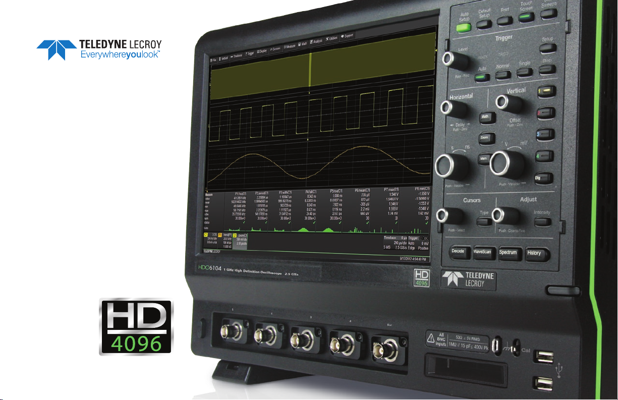
About the HDO6000 Oscillosocopes
Combining Teledyne LeCroy’s HD4096 high-definition technology
with long memory, a compact form factor, 12.1" touch screen display,
powerful measurement and analysis tools, and mixed signal capability,
the HDO6000 Oscillosocopes are ideal for circuit validation, system debug and waveform analysis. The powerful feature set provides analytical
tools and unique application packages to streamline the testing process.
Tools such as WaveScan Search and Find and History Mode, combined
with advanced triggering, identify and isolate problems while Spectrum
Analyzer Mode provides analysis tools in the frequency domain.
HD4096
HD4096 high-definition technology consists of high sample rate 12-bit
ADCs, high signal-to-noise input amplifiers, and a low-noise system
architecture. This technology enables HDO™ oscilloscopes to capture
and display signals up to 1 GHz with a high sample rate and 16 times
more resolution than other oscilloscopes.
Waveforms captured and displayed on the HDO6000 with HD4096
technology are cleaner and crisper. Signal details often lost in the noise
are clearly visible and easy to distinguish, and measurements can be
performed with unmatched precision for improved debug and analysis.
Mixed Signal Option
With embedded systems growing increasingly more complex,
powerful mixed signal debug capabilities are an essential part of
modern oscilloscopes. The 16 integrated digital channels and set of tools
designed to view, measure and analyze analog and digital signals enable
fast debugging of mixed signal designs. Flexible analog and digital
cross-pattern triggering across all 20 channels provides the ability to
quickly identify and isolate problems in an embedded system.
2
Spectrum Analyzer
Navigate waveforms in the frequency domain using spectrum analyzer
type controls and apply FFT measurements without worrying about
FFT set up.
WaveScan Search and Find
WaveScan® Search and Find allows you to search a single acquisition
using more than 20 different criteria. Or, set up a scan condition and
scan for an event over hours or even days.
History Mode
Never miss a waveform. History mode lets you scroll back in time
to view previous waveforms and isolate anomalies. Use cursors and
measurement parameters to quickly find the source of problems. History
mode is always available with a single button press, no need to enable
this mode.
LabNotebook Report Generator
Save and document all your waveforms, settings and screen images
through the LabNotebook report generation tool. With LabNotebook,
there’s no need to navigate multiple menus to save all these files
independently. Returning your oscilloscope to a past state is only one
button press away thanks to LabNotebook’s flashback feature.
923011-00 Rev A
Page 7

Specifications
Detailed specifications are maintained in the Datasheet on the product
page at teledynelecroy.com.
Key Specifications
Bandwidth 350 MHz–1 GHz
Channels 4
Sample Rate (all channels) 2.5 GS/s
Memory (per channel) 50 Mpts/ch
Digital Channels 16
Digital Sample Rate 1.25 GS/s
Minimum Detectable Pulse Width 2 ns
Maximum Input Frequency 250 MHz
923011-00 Rev A
Materials List
Check that you have all the parts listed here. Contact Teledyne
LeCroy immediately if any part is missing.
• 1 oscilloscope
• 4 passive probes (one for each channel)
• 1 AC power cord (rated for country)
• 1 protective front cover
• 1 Getting Started Guide
• 1 Oscilloscope Security Certificate
• 1 Oscilloscope Registration Card
• 1 Calibration Document
HDO6000-MS models also include:
• 1 digital leadset
• 5 flying ground leads
• 20 ground extenders
• 22 XL microgrippers
INTRODUCTION
3
Page 8

INTRODUCTION
4
General Safety Information
This section contains instructions that must be observed to keep the
instrument operating in a correct and safe condition. You are required
to follow generally accepted safety procedures in addition to the
precautions specified in this section. The overall safety of any system
incorporating this instrument is the responsibility of the assembler
of the system.
Symbols
These symbols appear on the instrument’s front or rear panels and in its
documentation to alert you to important safety considerations.
CAUTION of damage to instrument, or WARNING of hazard to
health. Attend to the accompanying information to protect against
personal injury or damage. Do not proceed until conditions are
fully understood and met.
WARNING. Risk of electric shock.
Measurement ground connection.
Safety (protective) ground connection.
Alternating Current.
On/Standby power.
Precautions
• Use proper power cord. Use only the power cord shipped with this
instrument and certified for the country of use.
• Maintain ground. This product is grounded through the power
cord grounding conductor. To avoid electric shock, connect only to a
grounded mating outlet.
• Connect and disconnect properly. Do not connect/disconnect
probes or test leads while they are connected to a voltage source.
• Observe all terminal ratings. Do not apply a voltage to any input
(C1, C2, C3, C4, EXT or Dig) that exceeds the maximum rating of
that input. Refer to the front of the oscilloscope for maximum input
ratings.
• Use only within operational environment listed. Do not use in
wet or explosive atmospheres.
• Use indoors only.
• Keep product surfaces clean and dry.
• Do not block the cooling vents. Leave a minimum six-inch gap
between the instrument and the nearest object. Keep the underside
clear of papers and other objects.
• Do not remove the covers or inside parts. Refer all maintenance to
qualified service personnel.
• Do not operate with suspected failures. Inspect all parts regularly
and do not use the product if any part is damaged. Cease operation
immediately and sequester the instrument from inadvertent use.
923011-00 Rev A
Page 9

Operational Environment
Temperature: 5° to 40° C
Humidity: Maximum relative humidity 90% for temperatures up to
31° C decreasing linearly to 50% relative humidity at 40° C
Altitudes: up to 3,000 m (at < 30° C)
Power and Ground Connections
The instrument operates from a single-phase, 100 to 240 Vrms (± 10%)
AC power source at 50/60/400 Hz (± 10%). The instrument automatically
adapts to the line voltage. Manual voltage selection is not required.
The AC inlet ground is connected directly to the frame of the instrument.
For adequate protection again electric shock, connect to a mating outlet
with a safety ground contact.
WARNING. Interrupting the protective conductor inside or outside
the oscilloscope, or disconnecting the safety ground terminal,
creates a hazardous situation. Intentional interruption is prohibited.
Maximum power consumption with all accessories installed (e.g., active
probes, USB peripherals, digital leadsets) is 320 W (320 VA). Power
consumption in standby mode is 4 W.
Cleaning
Clean only the exterior of the oscilloscope using a damp, soft cloth. Do
not use harsh chemicals or abrasive elements. Under no circumstances
submerge the instrument or allow moisture to penetrate it. Avoid
electric shock by unplugging the power cord from the AC outlet
before cleaning.
CAUTION. Do not attempt to clean internal parts.
923011-00 Rev A
Support
Online Documentation
Teledyne LeCroy publishes a free Technical Library on its website.
Manuals, tutorials, application notes, white papers, and videos are
available to help you get the most out of your Teledyne LeCroy products.
The HDO6000 Oscillosocopes Operator’s Manual can be downloaded
from teledynelecroy.com/HDO6000. This .PDF document contains
more extensive procedures for operating your oscilloscope than are
found here. You can also download Oscilloscope System Recovery Tools
and Procedures, which contains instructions for using Acronis® True
Image® Home included with the oscilloscope.
The Datasheet published on the product page contains the detailed
product specifications.
Technical Support
Registered users can contact their local Teledyne LeCroy service center
at the number listed in this guide to make Technical Support requests by
phone or email. You can also submit Technical Support requests via the
website at teledynelecroy.com/support/techhelp.
INTRODUCTION
5
Page 10

INTRODUCTION
6
923011-00 Rev A
Page 11

HDO6000 High Definition
Oscilloscopes
SET UP
Page 12
SET UP
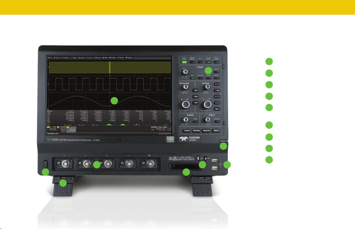
The Front of Your Oscilloscope
A
H
8
A
Touch Screen Display
B
C
EG
D
F
Front Panel
B
Built-in Stylus Holder
C
USB Ports
D
E
Ground and Calibration
Output Terminals
Mixed Signal Interface
F
Channel Inputs
G
Power Button
H
Rotating / Tilting Feet
I
I
923011-00 Rev A
Page 13
The touch screen display is the principal viewing and control center
of the oscilloscope. See “Touch Screen Display” for an overview of its
components.
The front panel houses buttons and knobs that control different
oscilloscope settings. For the most part, you can operate the instrument
using front panel hard controls, display soft controls, or a mix of both
that is convenient for you.
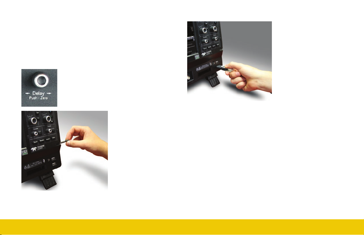
All front panel knobs have multiple modes of
operation: pressing them invokes one action and
turning them another. The labels below the knob
tell you what happens when you “Push” instead
of turn.
The built-in stylus holder
stores a stylus that can be
used with the touch screen
display.
923011-00 Rev A
Front mounted host USB ports
can be used for transferring
data or connecting peripherals
such as a mouse or keyboard.
The mixed signal intereface connects the digital leadset to input up-to-
16 digital lines (-MS models only).
Ground and calibration output terminals are used to compensate
passive probes.
Channel inputs 1–4 are signal inputs to the oscilloscope; Ext is for
connecting an external trigger device.
The Power button turns on/off the oscilloscope. See “Powering On/Off”
for more information.
The rotating, tilting feet enable four different viewing positions.
SET UP
9
Page 14
SET UP
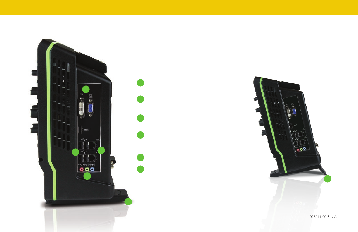
The Side of Your Oscilloscope
A
C
B
D
Video Output VGA, DVI, and HDMI ports
A
for connecting external monitors
Ethernet Ports (2) for connecting to
B
networks
USB Ports (4) for connecting external USB
C
devices
Audio Input/Output Speaker, Mic, and
D
Line-In for connecting external audio
devices
E
Feet rotated back
F
Feet rotated front and tilted
10
F
E
923011-00 Rev A
Page 15
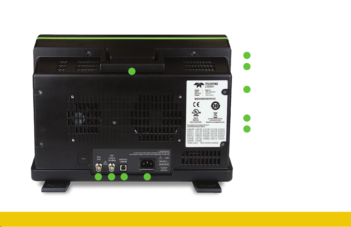
The Back of Your Oscilloscope
923011-00 Rev A
Built-in Carrying Handle
A
Aux Out connector to send device
A
B
trigger enabled, trigger out, or pass/
fail output to another device
Ref In/Out connector to input an
C
external Reference Clock, or to
output a Reference Clock to another
instrument
USBTMC Port for remote control
D
AC Power Inlet for the AC line cord
E
B
SET UP
D
C
E
11
Page 16

SET UP
12
Carrying
The oscilloscope’s case contains a built-in carrying handle. Lift the
handle away from the oscilloscope body, grasp firmly and lift the
instrument.
Always unplug the instrument from the power source before lifting and
carrying it.
Connecting
Make the desired cable connections. All except for the power
connection are optional.
After start up, configure the connection on the oscilloscope using the
menu options listed below. See the HDO6000 Oscilloscopes Operator’s
Manual for more detailed instructions.
Power
Connect the line cord rated for your country to the AC power inlet on the
back of the instrument, then plug it into a grounded AC power outlet.
(see Power and Ground Connections in “General Safety Information”).
LAN
Connect a cable from either Ethernet port on the side panel to a network
access device. On the oscilloscope, use the standard Windows Network
dialog to configure the network connection. Go to Utilities > Preference
Setup > Email to configure email settings.
USB Peripherals
Connect the device to a USB port on the front or side of the instrument.
Go to Utilities > Utilities Setup > Hardcopy to configure printer settings.
External Monitor
Connect the monitor cable to a video output on the side of the instrument
(VGA, DVI, and HDMI are all supported). Go to Display > Display Setup >
Open Monitor Control Panel to configure the display settings.
External Controller
Connect a USB-A/B cable from the USBTMC port on the back of the
instrument to the controller. Go to Utilities > Preference Setup >
Remote to configure remote control.
Other Oscilloscope (for Reference Clock)
Connect a BNC cable from Ref In/Out on the back of the instrument to
the other instrument. Go to Timebase > Horizontal Setup > Reference
Clock to configure the clock.
Other Auxiliary Device
Connect a BNC cable from Aux Out on the back of the instrument to the
other device. Go to Utilities > Utilities Setup > Aux Output to configure
the connection.
923011-00 Rev A
Page 17

Powering On/Off
The Power button controls the operational state of the oscilloscope.
Press the button to switch on the instrument; press it again to switch “off”
(i.e., Standby power).
CAUTION. Do not change the instrument’s Windows
Power Options from the default Never to System Standby
or System Hibernate modes.
CAUTION. Do not power on or calibrate the oscilloscope with
any signal attached.
Always use the Power button or the File > Shutdown menu option to
execute a proper shut down process and preserve settings. Pressing
and holding the button will execute a “hard” shutdown, the same as on
a computer, but we do not recommend doing this because it does not
allow the Windows operating system to shut down properly.
The Power button does not disconnect the oscilloscope from the AC
power supply; some “housekeeping” circuitry continues to draw power.
The only way to fully power down the instrument is to use the Power
button or the File > Shutdown command, then unplug the AC line cord
from the outlet.
CAUTION. Do not place the instrument so that it is difficult
to reach the power cord in case you need to disconnect
from power.
We recommend unplugging the instrument if it will remain unused for a
long period of time.
®
923011-00 Rev A
Software Activation
The oscilloscope operating software (firmware and standard applications)
is active upon delivery.
Software Updates
Free firmware updates are available periodically from the Teledyne
LeCroy website at teledynelecroy.com/support/softwaredownload.
Registered users will receive email notification when a new update is
released. Follow the instructions on the website to download and install
the software.
Purchasing Software Options
Many optional software packages may be purchased to extend the
functionality of the oscilloscope software. Refer to “Software Options”
for more information.
Probes
HDO6000 Oscilloscopes are compatible with the included passive
probes and all Teledyne LeCroy ProBus active probes that are rated for
the oscilloscope’s bandwidth. Probe specifications and documentation
are available at teledynelecroy.com/HDO6000.
SET UP
13
Page 18

SET UP
Digital Leadset
Standard with all HDO6000-MS model oscilloscopes, the digital leadset
enables input of up-to-16 lines of digital data. Lines can be organized into
four logical groups and can be named appropriately.
The digital leadset features two digital banks with separate threshold and
hysteresis controls, making it possible to simultaneously view data from
different logic families.
Each flying lead has a signal and ground connection. A variety of
ground extenders and flying ground leads are available for different
probing needs. In order to achieve optimal signal integrity, you should
connect the ground at the tip of the flying lead for each channel used in
your measurements. Use either the provided ground extenders or ground
flying leads to make the ground connection.
14
To connect the leadset to the oscilloscope, push the connector into the
mixed signal interface below the front panel until you hear a click.
To remove the leadset, press in and hold the buttons on each side of the
connector, then pull out to release it.
923011-00 Rev A
Page 19

HDO6000 High Definition
Oscilloscopes
USER INTERFACE
923011-00 Rev A
Page 20

USER INTERFACE
16
Touch Screen Display
The entire display is a touch screen. Use your finger or the stylus to touch, double-touch, touch-and-drag, touch-and-hold (right click) and draw a
selection box. Many controls that display information also work as “buttons” to access other functions. If you have a mouse installed, you can click
anywhere you can touch to activate a control; in fact, you can alternate between clicking and touching, whichever is convenient for you.
A
Menu Bar
A
Grid Area
B
Trigger Level Indicator
B
C
D
C
Cursor
D
Channel Descriptor Box
E
Trigger Position Indicator
F
F
Timebase and Trigger
E
G
G
Descriptor Boxes
H
H
Dialog Tabs
923011-00 Rev A
Page 21

A menu bar of drop-down menus lets you access set up dialogs and
other functions. All functionality can be accessed through either the
menu bar or other shortcuts.
If an action can be “undone” (such as recalling a setup), a small
Undo button appears at the far right of the menu bar. Click this
to return to the previous oscilloscope display.
The grid area displays the waveform traces. You can adjust the
brightness of the grid lines to make other objects more visible.
Trigger level (vertical axis) and trigger position (horizontal axis)
indicators appear on the grid when a trigger is set, color-coded to match
the input.
Cursors show where measurement points have been set. Touch-anddrag cursor indicators to quickly reposition the measurement point.
Channel (C1-C4), Zoom (Z1-Z4), Math (F1-F8), Memory (M1-M4), and
Digital (Digital1-Digital4, on -MS models only) descriptor boxes appear
immediately below the grid and summarize current settings for each
open trace. Touch the descriptor box to open the corresponding set
up dialog.
Timebase and Trigger descriptor boxes appear at the right of the
display. Timebase and Trigger settings only apply to channel traces.
Touch the descriptor box to open the corresponding set up dialog.
Dialogs appear at the bottom of the display for entering set up data.
The top dialog will be the main entry point for the selected function.
For convenience, related dialogs appear as a series of tabs behind the
main dialog. Touch the tab to open the dialog.
Timebase Descriptor Box
E
D
Channel Descriptor Box
A
F
Digital Descriptor Box
923011-00 Rev A
Trigger Delay (Position)
A
B
A
B
C
B
C
D
E
A
B
C
Time/div
C
Sample Rate
# Samples
D
Sampling Mode
E
(blank when in real-time mode)
Pre-Processing Summary
A
Listing (summarizes changes
from default states)
Coupling
B
Gain Setting
C
Offset Setting
D
Averaging Sweeps Count
E
Channel Abbreviation
F
A
# Digital Lines in Group
Digital Sample Rate
B
Digital Memory
C
USER INTERFACE
17
Page 22

USER INTERFACE
Shortcut Toolbar Language Selection
These buttons on the main Channel, Math, Memory and Digital dialogs
offer shortcuts to useful functions so that you don’t have to leave the
underlying dialog. They always apply to the active (highlighted) trace.
Apply up-to-eight measurement parameters.
Display a zoom of the trace.
Apply a pre-defined or custom math function.
Open the Serial Decode dialog.
Copy the active trace to an internal memory
(e.g., C2 to M2).
Scale the waveform to fit the grid.
To change the language that appears on the display, go to Utilities >
Preference Setup > Preferences and make your Language selection.
The oscilloscope software must be restarted after the language is selected.
If you wish to also change the language of the Windows operating system:
1. Choose File > Minimize to hide the oscilloscope display and show the
Windows Desktop.
2. From the Windows task bar, choose Start > Control Panel >
Clock, Language and Region.
3. Under Region and Language select Change Display Language.
4. Click the Install/Uninstall Languages button.
5. Select Install Language and Browse Computer or Network.
6. Click the Browse button, navigate to D:\Lang Packs\ and select the
language you want to install. The available languages are: German,
Spanish, French, Italian, and Japanese. Follow the installer prompts.
NOTE: Other language packs are available from Microsoft’s website.
7. After exiting the Control Panel, click the oscilloscope icon in the
lower-right corner of the desktop to maximize the oscilloscope display.
18
Move the active trace to the next grid.
Apply a custom label to a waveform.
923011-00 Rev A
Page 23

Entering/Selecting Data
Touch & Type
Touching once
activates a control.
In some cases, you’ll
immediately see a
pop-up menu of
options. Touch one
to select it.
If you have a keyboard installed, you can type
your entry in the active field. Or, you can touch
again, then select your entry from the pop-up
menu or keypad.
You’ll see a pop-up keypad when you doubletouch a numerical data entry field. Touch the
soft keys to use it exactly as you would a
calculator. When you touch OK, the calculated
value is entered in the field.
In other cases, data
entry fields appear
highlighted on the
display. When a
data entry field is highlighted (as
shown above), it is active and can
be modified by using the front
panel Adjust knob.
923011-00 Rev A
Touch & Swipe
Touch and swipe the screen in an up or down direction to scroll long lists of
values. You can also use scroll bars or Up/Down arrow keys to navigate to
the desired value.
USER INTERFACE
19
Page 24

USER INTERFACE
20
Touch & Drag
Touch-and-drag waveforms, cursors and trigger indicators to reposition
them on the grid; this is the same as setting the values on the dialog.
Quickly zoom areas of the grid by touching and dragging to draw a selection
box around a portion of the trace.
Stylus
Use the stylus when you want a more precise selection tool than your
finger. It is especially helpful for selecting exact areas of the grid or values
that lie close together on pop-up menus.
923011-00 Rev A
Page 25

Front Panel
Most of the front panel controls duplicate functionality available through the
touch screen display. They are covered in more detail in the Basics section
and in the HDO6000 Oscilloscopes Operator’s Manual. Below are a few
useful front panel controls.
Shortcut buttons arranged across the top of the front panel give quick
access to commonly used functions.
The Print button captures the entire screen and sends it to a printer, saves
it to a file, or creates a Notebook Entry in LabNotebook.
The Touch Screen button enables or disables touch screen functionality.
Other shortcut buttons arranged across the bottom open special
applications.
All of the knobs on the front panel function one way if turned and another
if pushed like a button. The top label describes the knob’s principal “turn”
action, and the bottom label describes its “push” action.
Front panel buttons light up to indicate which functions are active.
923011-00 Rev A
USER INTERFACE
21
Page 26
USER INTERFACE
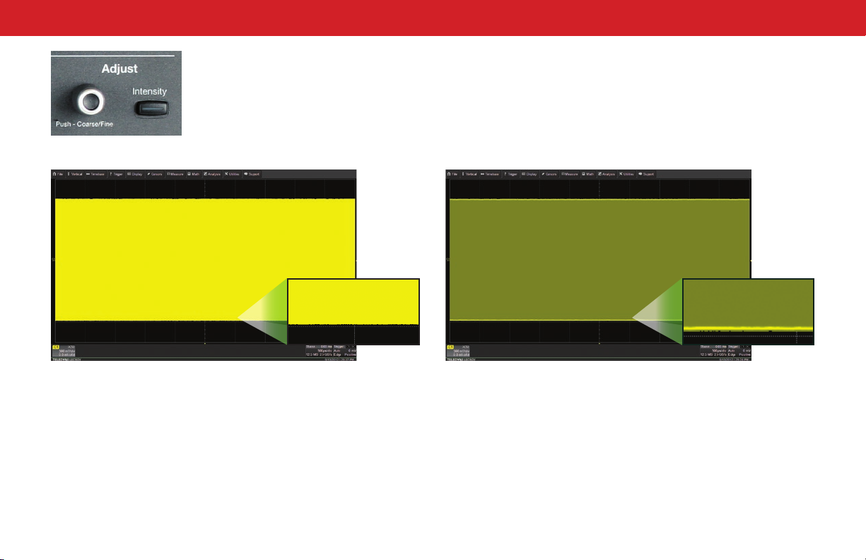
The Adjust knob changes the value in any
highlighted data entry field when turned.
Pushing the Adjust knob toggles between
coarse (large increment) or fine (small
increment) adjustments when the knob
is turned.
With Intensity 100% With Intensity 40%
The Intensity button sets the Adjust knob to control the trace intensity.
When more data is available than can actually be displayed, the Intensity
button helps to visualize significant events by applying an algorithm that
dims less frequently occurring samples. This feature can also be accessed
from the Display > Display Setup dialog.
22
923011-00 Rev A
Page 27

BASICS
923011-00 Rev A
HDO6000 High Definition
Oscilloscopes
REFERENCE
23
Page 28

BASICS
24
Turning On/Off Traces
From the Front Panel
Press the corresponding Channel button (1–4) to turn on a trace and make
it active. To turn off an active trace, press the button again.
A trace (waveform pattern) appears on the grid with a color-coded Channel
descriptor box below it. This box always displays the current settings for the
trace and is labeled C1–C4.
To open digital traces (-MS models only), press the Dig button. Digital trace
descriptors are labeled Digital1-Digital4.
From the Display
Choose Vertical > Channel<#> Setup to turn on the trace and make it
active. To turn off the trace, touch the descriptor box, then clear the Trace
On checkbox on the Channel dialog.
For digital traces, choose Vertical > Digital<#> Setup. Turn off the trace by
clearing the Group checkbox.
Zoom, Math, and Memory Traces
In addition to the channel and digital traces, you can view a zoom (close-up
portion) of a trace (Z1-Z4), a trace previously stored to the oscilloscope’s
memory (M1-M4), or a trace that displays the result of a math function
applied to one or more source traces (F1-F8). The quickest way to turn
on these traces is to use the front panel Zoom, Math, and Memory
buttons, which open the corresponding trace setup dialogs. Adjust a trace
individually by touching its descriptor box and changing dialog settings.
If multiple channel traces are open and you press Zoom, zoom traces are
created for each channel.
Active vs. Inactive Trace
A highlighted descriptor box indicates the “active” trace, and all display and
front panel actions will apply to that trace until another is selected. This is
true for all traces, regardless of the type. Although several traces may be
open and appear on the grid, only one at a time is active.
Inactive. Controls will not
work for this trace.
Also, the front panel Channel buttons (1-4) and the Dig, Mem, Zoom, and
Math buttons will light up to indicate the active trace.
Active. Controls will
work for this trace.
Viewing Multiple Traces
By default, the oscilloscope has Auto Grid enabled. This divides the grid
each time a new trace is opened, up to 16 grids for simultaneous viewing.
There are Display menu options to show all traces on a Single Grid, or to
manually divide the grid up to eight times. When you manually divide the
grid, zooms and measurement markers appear on the same grid as the
source channel, while math and memory traces appear in new grids until
none are available.
Manually move traces from grid to grid using the Next Grid shortcut
button.
923011-00 Rev A
Page 29

Vertical
These controls adjust the channel trace along the Y axis.
923011-00 Rev A
From the Front Panel
A
B
C
D
Press to activate analog trace.
A
Turn to raise or lower Offset (analog)
B
or Vertical Position (digital). Push to
return to zero.
Turn to raise or lower Vertical Scale
C
(analog) or Group Height (digital).
Push to adjust with more precision.
Press to activate digital trace
D
(-MS models only).
Analog Traces From the Display
Touch to activate the trace and
again to open the Channel dialog.
A
B
A
Touch any control to change the value.
Use the Up/Down buttons to change Vertical Scale or Offset.
B
BASICS
25
Page 30
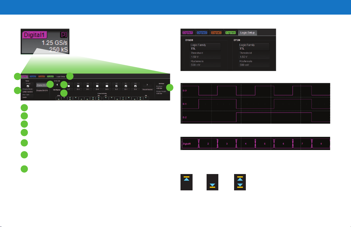
Digital Traces From the Display
Touch to activate the digital trace and
again to open the Digital dialog.
A
C
B
Touch tab to choose digital group (1-4).
A
Choose to display individual digital lines, bus trace or both.
B
Touch arrows to switch between banks 0-7 and 8-15.
C
Touch checkbox to select the lines in the group.
D
Enter Vertical Position (top of lowest bit relative to center) and Group
E
Height (vertical space occupied by group) in divisions.
Watch Line Activity Indicators instead of line traces to quickly see the
F
state of each digital line.
Touch to open Logic Setup dialog.
G
G
D
F
BASICS
E
Line trace shows high, low and transition points for each line.
Bus trace collapses lines into hex values.
Line Activity Indicators
26
Choose a standard
Logic Family, or
enter custom values
for Threshold and
Hysteresis. Separate
controls allow you to
set different values for
each bank.
High
Low
Transitioning
923011-00 Rev A
Page 31

Horizontal (Timebase)
These controls adjust the trace along the X axis.
923011-00 Rev A
From the Front Panel
Turn to raise or lower trigger Delay. Push to return
A
Delay to zero.
Turn to raise or lower Horizontal Scale (Time/div).
A
B
Push to adjust scale with more precision on math,
memory, or zoom traces.
B
From the Display
Touch to open the Timebase dialog.
A
A
Touch to select a Sampling Mode.
Use the Up/Down buttons to change Time/Division.
B
Enter a Delay or use the button to Set To Zero.
C
B
C
BASICS
27
Page 32

Zoom
Zoom traces display a close-up portion of a channel trace.
From the Front Panel
BASICS
From the Display
28
Draw a zoom box on a portion of a
Channel trace.
Press the Zoom button.
Zoom trace opens for every channel trace. The zoomed portion of the
original trace is highlighted.
Use Vertical knobs to adjust V/div.
Use Horizontal knobs to adjust Time/div.
Repeat on another section to open
a new zoom trace.
OR
A
C
B
Touch Channel descriptor box to activate the trace.
A
Touch the Zoom shortcut button.
B
Touch Zoom descriptor to open the Zoom dialog and adjust values.
C
923011-00 Rev A
Page 33

Triggers
Triggers tell the oscilloscope when to perform an acquisition.
Available trigger types are described at more length in the
HDO6000 Oscilloscopes Operator’s Manual.
From the Front Panel
From the Display
Touch to open Trigger dialog.
A
B
F
E
C
D
Trigger Source
A
Trigger Coupling
B
Trigger Level
C
D
Trigger Slope
E
Trigger Type
F
Trigger Status
923011-00 Rev A
F
E
Opens the Trigger dialog.
A
Stops the oscilloscope from acquiring data.
B
Triggers once (single-shot acquisition) when all conditions are met.
C
Triggers repeatedly whenever all conditions are met.
D
Same as Normal when there is a valid trigger; triggers after a preset
E
period when there is no valid trigger.
Turn to raise or lower Trigger Level (V). Push to automatically find
F
the level.
Lights up when a trigger is armed.
G
Lights up when a trigger has fired.
H
HG
D
C
A
B
G I
G
Touch to choose trigger Type.
H
Touch to set Trigger Level (V).
I
Touch to let the software automatically set trigger level
based on the input signal.
Trigger Indicators
Level
Indicator
Position
Indicator
Pre/Post-Trigger Indicator appears at
the edge of the grid when a trigger
point is no-longer visible.
BASICS
H
29
Page 34

Cursors
Cursors set measurement points on a trace. There are five preset cursor
types, each with a unique appearance on the display: Horizontal (Time),
Horizontal + Vertical, Vertical (Amplitude), Horizontal (Frequency), and
Horizontal (Event). These are described in more detail in the HDO6000
Oscilloscopes Operator’s Manual.
From the Front Panel
Press to apply cursor. Continue
A
pressing to cycle through all
B
A
cursor types.
Turn to adjust cursor position.
B
Push to select different cursor
lines to adjust.
BASICS
From the Display
A
C
D
B
A
Choose Cursor > Cursor Setup to open the Cursor dialog
Touch to choose Cursor Type.
B
Touch-and-drag cursor line to reposition cursor.
C
Vertical Cursor readout appears on descriptor boxes.
D
Horizontal Cursor readout appears below Timebase.
E
30
E
923011-00 Rev A
Page 35

923011-00 Rev A
Measurements & Statistics
Measurements are waveform parameters that can be expressed as numerical values, such as amplitude or frequency. You can set up-to-eight
simultaneous measurements on one or more channel traces and view the active readout in a table. Statistical measurements can be added to the
table of parameter values. You can also view measurements as a histicon, a miniature histogram. Levels can be set for certain parameters that
required them. Measurements gates can be used to only perform measurements on a specific portion of the waveform.
Choose Measure > Measure Setup to open the
A
A
B
D
C
H
J
E
F
G
Measure dialog.
B
Touch to re-open Measure dialog.
Statistics can be added to the readout.
C
Readout of parameter values.
D
Touch to show table of parameter values.
E
Touch to choose source channel.
F
Touch to choose parameter.
G
Touch P<#> tab to see parameter details.
H
Touch to display Histogram, Trend, or Track of
I
parameter measurements.
Touch to set measurement gates.
J
I
BASICS
31
Page 36
BASICS
32
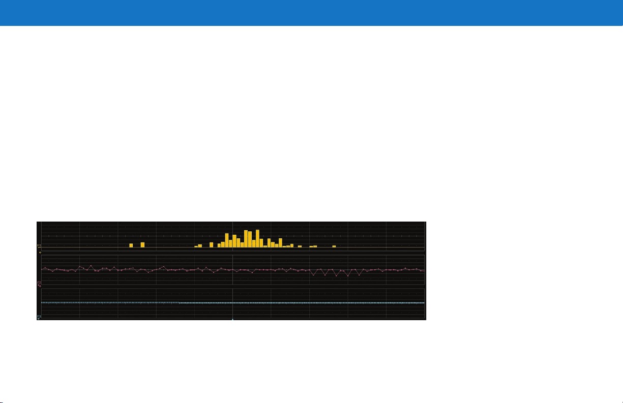
Histogram
Histograms represent the statistical distribution of measurement values within an incremental range (bin) as a bar chart. Touch the Parameter tab
(P<#>), then touch the Histogram button to open a histogram of that parameter in a new grid.
Trend
A trend is a waveform composed of a series of parameter measurements in the order the measurements were taken. The vertical units are those of
the source parameter, the horizontal unit is measurement number. The trend contains a single value for each measurement. Touch the Parameter tab
(P<#>), then touch the Trend button to open a new grid showing the trend of that parameter.
Track
A track is a waveform composed of parameter measurements that is time synchronous with the source waveform. The vertical units are those of the
source parameter and the horizontal units are seconds. In order to maintain time synchronism, the parameter values are posted at the sampling rate.
Track values are redundant in that the same value is repeated every sample period until the measurement changes. Touch the Parameter tab (P<#>),
then touch the Track button to open a histogram of that parameter in a new grid.
923011-00 Rev A
Page 37

923011-00 Rev A
Math
Math traces display the result of applying a mathematical function (e.g., FFT) to one or more channel traces. One important distinction between math
functions and measurement parameters is that the result of math is always another waveform, whereas the result of measurement is a number.
Choose Math > Math Setup or press
A
front panel Math button to open
A
C
E
D
B
Math dialog.
Check to turn on existing function.
B
Math trace (F1-F8) opens in
C
separate grid.
Touch F<#> tab or button and select
D
Trace On. (Deselect Trace On to
close trace). Choose Source channel
and math Operator.
Math descriptor box shows math
E
scaling. Touch to re-open function
tab and adjust trace.
BASICS
33
Page 38

BASICS
34
Spectrum Analyzer
The Spectrum Analyzer software lets you quickly and easily use the Fast Fourier Transform (FFT) for frequency analysis. The controls are the same
as you would find on an RF spectrum analyzer. You set the inputs and desired frequency span, and the oscilloscope automatically generates output in
units relevant to the frequency domain. A spectrogram generator displays 2D or 3D renderings of historical data.
Choose Analysis > Spectrum
A
G
F
E
B
A
Analyzer to access the Spectrum
Analyzer dialog.
Open/close FFT trace.
B
Choose type and source of input.
C
Specify frequency span of interest.
D
Automatically mark and tabulate
E
peaks, or set measurement markers
on frequencies.
2D or 3D spectrogram shows history
F
of spectra; 2D can be shifted on two
axes; 3D can be rotated around three
axes.
Tabular readout of marker
G
measurements.
C
D
923011-00 Rev A
Page 39

Memories (Reference Waveforms)
Memories are traces stored for reference. They can be recalled to the
display for comparison with other traces. A memory can be zoomed or
measured for better analysis of historical data. You can store up-to-four
internal memories (M1-M4). After that, new memories will overwrite
previously stored data.
Internal memories only persist until the oscilloscope is rebooted. To
store memories indefinitely, save them to an external file by choosing
File > Save Waveform. The file can then be recalled into one of the four
internal memories for viewing by choosing File > Recall Waveform. Only
memory files saved with the extension .trc can be recalled.
Press the front panel Mem(ory) button to open the Memory dialog.
B
To turn on stored memory, check On next to M1-M4.
A
To store new memory, touch M1-M4 button or tab.
B
A
C
D
Select source trace in Copy From Waveform.
C
Touch to copy to internal memory.
D
E
Make any other adjustments to stored waveform.
E
923011-00 Rev A
BASICS
35
Page 40

BASICS
36
Documenting
HDO6000 Oscilloscopes offer several ways to preserve and share data—such as print, save to file, email, or save as Notebook Entry— any of which
can be associated with the front panel Print button.
Go to Utilities > Utilities Preferences > Hardcopy Setup to configure how the
oscilloscope handles the Print command. To make Print create a new Notebook
Entry, go to File > LabNotebook > Preferences and select Create Entry when
Hardcopy Pressed. Pressing Print captures an image of the display, which will then
be handled according to your chosen Print method.
Sending Data
If you have email set up on the oscilloscope, LabNotebook reports and other saved files can be sent directly from the instrument. They can also be
transferred to a USB drive through any of the host USB ports on the instrument. Use the Windows Explorer to transfer files from your save folder.
LabNotebook
The integrated LabNotebook tool lets you build reports containing waveform images and custom annotations right on the oscilloscope. You create
individual Notebook Entries as you work, which are saved to a resident database. When you choose File > LabNotebook, the LabNotebook dialog
opens showing all your Notebook entries. Choose which entries to export, the report file format and the output location. You can also use the
LabNotebook Flashback feature to put the oscilloscope back to the exact state it was in when the Notebook Entry was saved. See the HDO6000
Oscilloscopes Operator’s Manual for more information on using LabNotebook.
923011-00 Rev A
Page 41

923011-00 Rev A
Temperature Dependent Calibration
The HDO6000 is calibrated at the factory prior to being shipped. This calibration is run at 23° C (± 2° C) and is valid for temperatures ± 5° C of the
original calibration temperature. Within this temperature range the HDO6000 will meet all of the specifications. When the oscilloscope is used outside
of this temperature range a temperature dependent calibration is recommended. There are two options for this calibration: Calibrate All or Calibrate
Current Setting.
Calibrate All - All possible combinations of vertical and horizontal settings are calibrated at the current temperature. This calibration is valid for the
current temperature ± 5° C. This calibration takes about 50 minutes.
Calibrate Current Setting - The oscilloscope is calibrated at the current vertical and horizontal setting. This calibration is valid for this setting for the
current temperature ± 5° C. This calibration takes under 30 seconds.
It is recommended that the HDO6000 be calibrated when the temperature range is outside of the ± 5° C of the original calibration temperature or
when it has been more than 1 month since the previous calibration.
It is recommended that the HDO6000 be warmed up for at least 20 minutes prior to use. During the HDO6000 warm-up period, the oscilloscope will
automatically initiate calibrations to ensure that the HDO6000 is always calibrated.
It is required that all inputs be removed from the oscilloscope prior to performing calibration.
BASICS
37
Page 42

BASICS
38
Software Options
You may purchase these optional software packages to enhance the
operation of an HDO6000 Oscilloscope.
Available Software Options
Power Analysis Option (HDO6K-PWR) — Provides exceptional ability
to measure and analyze the operating characteristics of power
conversion devices and circuits. The Power Analysis option is used with
Teledyne LeCroy oscilloscopes to make critical power switching device
measurements, perform control loop modulation analysis, and measure
line power harmonics.
JITKIT (HDO6K-JITKIT) — JITKIT makes it easy to understand the
basic system jitter performance of clock signals and clock-data activities,
including period, half period, cycle-cycle, skew, amplitude, differential
voltage crossing, slew rate, and a wide variety of common jitter
measurements.
Serial Trigger/Decode and Other Options (see table at right) — There
are many serial trigger and decode options available that provide added
insight when debugging particular serial data standards. For the most up
to date list, go to teledynelecroy.com/serialdata.
How to Purchase and Install Options
To purchase an option, contact your Teledyne LeCroy sales representative
at the number listed in this guide. You will receive a license key via email
that activates the optional features on the oscilloscope. To install the key:
1. Go to Utilities > Utilities Setup > Options.
2. Touch Add Key.
3. Enter the new license key and click OK.
4. Reboot the oscilloscope software.
Part Number Description
HDO6K-1553 TD MIL-STD-1553 Trigger and Decode Option
HDO6K-ARINC429BUS Dsymbolic ARINC 429 Symbolic Decode Option
HDO6K-Audiobus TD/TDG Audiobus Trigger and Decode Options for
HDO6K-CANbus TD/TDM Can Trigger and Decode Options
HDO6K-DFP2 Digital Filter Package
HDO6K-DigRF3Gbus D DigRF 3G Decode Option
HDO6K-DigRFv4bus D DigRF v4 Decode Option
HDO6K-DPHYbus D D-PHY Decode Option
HDO6K-EMB I
HDO6K-EMC Electromagnetic Compliance Package
HDO6K-ENETbus D 10M and 100M ENET Decode Option
HDO6K-ET-PMT Electrical Telecom Mask Test Package
HDO6K-FlexRaybus TD/TDP FlexRay Trigger and Decode Options
HDO6K-I2Cbus TD I
HDO6K-LINbus TD LIN Triggewr and Decode Option
HDO6K-Manchester D Manchester D Decode Option
HDO6K-NRZ D NRZ Decode Option
HDO6K-PROTOBUS MAG PROTOBUS MAG Decode Option
HDO6K-SDM Serial Data Mask Package
HDO6K-SENTbus D SENT Decode Option
HDO6K-SPIbus TD SPI Trigger and Decode Option
HDO6K-UART-RS232bus TD UART and RS232 Trigger and Decode Option
HDO6K-USB2bus D USB 2.0 Decode Option
HDO6K-USB2-HSICbus D USB-HSIC Decode Option
HDO6K-VBA Vehicle Bus Analyzer Option
HDO6K-XDEV Advanced Customization Package
2
I
S, LJ, RJ and TDM
2
C, SPI, UART and RS-232 Trigger and Decode
2
C Trigger and Decode Option
923011-00 Rev A
Page 43

BASICS
REFERENCE
39
HDO6000 High Definition
Oscilloscopes
923011-00 Rev A
Page 44

Service
Contact your local Teledyne LeCroy service center for calibration or
other service.
Returning a Product
If the product cannot be serviced on location, the service center will
give you a Return Material Authorization (RMA) code and instruct
you where to ship the product. All products returned to the factory must
have an RMA.
Return shipments must be prepaid. Teledyne LeCroy cannot accept
COD or Collect shipments. We recommend air-freighting. Insure the
item you’re returning for at least the replacement cost.
Follow these steps for a smooth product return.
1. Remove all accessories from the device. Do not include the manual.
2. Pack the product in its case, surrounded by the original packing
material (or equivalent).
3. Label the case with a tag containing:
• The RMA
• Name and address of the owner
• Product model and serial number
• Description of failure or requisite service
4. Pack the product case in a cardboard shipping box with adequate
padding to avoid damage in transit.
5. Mark the outside of the box with the shipping address given to you
by Teledyne LeCroy; be sure to add the following:
• ATTN: <RMA code assigned by Teledyne LeCroy>
• FRAGILE
REFERENCE
6. If returning a product to a different country:
• Mark the shipment as a Return of US manufactured goods for
warranty repair/recalibration.
• If there is a cost for the service, list the cost in the Value column
and the original purchase price For insurance purposes only.
• Be very specific about the reason for shipment. Duties may have to
be paid on the value of the service.
Service Plans
Extended warranty, calibration, and upgrade plans are available for
purchase. Contact your Teledyne LeCroy sales representative or
customersupport@teledynelecroy.com to purchase a service plan.
40
923011-00 Rev A
Page 45

Teledyne LeCroy Service Centers
923011-00 Rev A
United States and Canada
World Wide Corporate Office
Teledyne LeCroy
700 Chestnut Ridge Road
Chestnut Ridge, NY, 10977-6499
Ph: 800-553-2769 / 845-425-2000
Fax: 845-578-5985
teledynelecroy.com
Support:
contact.corp@teledynelecroy.com
Sales:
customersupport@teledynelecroy.com
Taiwan
LeColn Technology Co Ltd.
Far East Century Park, C3, 9F
No. 2, Chien-8th Road
Chung-Ho Dist., New Taipei City,
Taiwan
Ph: ++ 886 2 8226 1366
Fax: ++ 886 2 8226 1368
sales_twn@teledynelecroy.com
US Protocol Solutions Group
Teledyne LeCroy
3385 Scott Boulevard
Santa Clara, CA, 95054
teledynelecroy.com
Sales and Service:
Ph: 800-909-7211 / 408-727-6600
Fax: 408-727-0800
contact.corp@teledynelecroy.com
Support:
Ph: 800-909-7112/408-653-1260
psgsupport@teledynelecroy.com
Korea
Teledyne LeCroy Korea
10th fl. Ildong Bldg.
968-5 Daechi-dong, Gangnam-gu
Seoul 135-280, Korea
Ph: ++82 2 3452 0400
Fax: ++82 2 3452 0490
Europe
Teledyne LeCroy SA
4, Rue Moïse Marcinhes
Case postale 341
1217 Meyrin 1
Geneva, Switzerland
Ph: +41 22 719 2228 / 2323 / 2277
Fax: +41 22 719 2233
contact.sales@teledynelecroy.com
applications.indirect@teledynelecroy.com
teledynelecroy.com/europe
Protocol Analyzers:
Ph: +44 12 765 0397 1
China
Teledyne LeCroy Beijing
Rm. 2001 Unit A, Horizon Plaza
No. 6 Zhichun Rd., Haidian Dist.
Beijing 100088, China
Ph: ++86 10 8280 0318 / 0319 / 0320
Fax: ++86 10 8280 0316
Service:
Rm. 2002
Ph: ++86 10 8280 0245
Singapore
Oscilloscopes:
Teledyne LeCroy Singapore Pte Ltd.
Blk 750C Chai Chee Road #02-08
Singapore 469003
Ph: ++ 65 64424880
Fax: ++ 65 64427811
Protocol Analyzers:
Genetron Singapore Pte Ltd.
37 Kallang Pudding Road, #08-08
Tong Lee Building Block B
Singapore 349315
Ph: ++ 65 9760-4682
Japan
Teledyne LeCroy Japan
Hobunsya Funchu Bldg, 3F
3-11-5, Midori-cho, Fuchu-Shi
Tokyo, 183-0006 Japan
Ph: ++ 81 4 2402 9400
Fax: ++ 81 4 2402 9586
teledynelecroy.com/japan
REFERENCE
41
Page 46

Certifications
This section certifies the instrument’s Electromagnetic Compatibility
(EMC), Safety and Environmental compliance.
EMC Compliance
EC DECLARATION OF CONFORMITY - EMC
The oscilloscope meets intent of EC Directive 2004/108/EC for
Electromagnetic Compatibility. Compliance was demonstrated to the
following specifications listed in the Official Journal of the European
Communities:
EN 61326-1:2006, EN 61326-2-1:2006 EMC requirements for electrical
equipment for measurement, control, and laboratory use.
Electromagnetic Emissions:
CISPR 11:2003, Radiated and Conducted Emissions Group 1, Class A
EN 61000-3-2:2006 Harmonic Current Emissions, Class A
EN 61000-3-3/A2:2005 Voltage Fluctuations and Flickers, Pst = 1
Electromagnetic Immunity:
EN 61000-4-2:2001 Electrostatic Discharge, 4 kV contact, 8 kV air, 4 kV
vertical/horizontal coupling planes
4
EN 61000-4-3:2006 RF Radiated Electromagnetic Field, 3 V/m, 80-1000
MHz; 3 V/m, 1400 MHz - 2 GHz; 1 V/m, 2 GHz - 2.7 GHz
EN 61000-4-4:2004 Electrical Fast Transient/Burst, 1 kV on power supply
lines, 0.5 kV on I/O signal data and control lines
4
EN 61000-4-5:2006 Power line Surge, 1 kV AC Mains, L-N, L-PE, N-PE
EN 61000-4-6:2007 RF Conducted Electromagnetic Field, 3 Vrms, 0.15
MHz - 80 MHz
EN 61000-4-11:2004 Mains Dips and Interruptions, 0%/1 cycle, 70%/25
cycles, 0%/250 cycles
4
4 5
1
2 3
4
4
REFERENCE
1
To ensure compliance with all applicable EMC standards, high quality shielded interface cables
should be used.
2
Emissions which exceed the levels required by this standard may occur when the oscilloscope is
connected to a test object.
3
This product is intended for use in nonresidential areas only. Use in residential areas may cause
electromagnetic interference.
4
Meets Performance Criteria “B” limits of the respective standard: during the disturbance, product
undergoes a temporary degradation or loss of function or performance which is self-recoverable.
5
Performance Criteria “C” applied for 70%/25 cycle voltage dips and for 0%/250 cycle voltage
interruption test levels per EN61000-4-11.
42
European Contact:
Teledyne LeCroy Europe GmbH
Waldhofer Str 104
D-69123 Heidelberg
Germany
Tel: (49) 6221 82700
AUSTALIA & NEW ZEALAND DECLARATION OF CONFORMITY – EMC
Oscilloscope complies with the EMC provision of the Radio Communications
Act per the following standards, in accordance with requirements imposed
by Australian Communication and Media Authority (ACMA):
CISPR 11:2003 Radiated and Conducted Emissions, Group 1, Class A, in
accordance with EN61326-1:2006 and EN61326-2-1:2006.
Australia / New Zealand Contacts:
Vicom Australia Ltd. Vicom New Zealand Ltd.
1064 Centre Road 60 Grafton Road
Oakleigh, South Victoria 3167 Auckland
Australia New Zealand
923011-00 Rev A
Page 47

Safety Compliance
EC DECLARATION OF CONFORMITY – LOW VOLTAGE
The oscilloscope meets intent of EC Directive 2006/95/EC for Product
Safety. Compliance was demonstrated to the following specifications as
listed in the Official Journal of the European Communities:
EN 61010-1:2010 Safety requirements for electrical equipment for
measurement, control, and laboratory use – Part 1: General requirements
EN 61010-2:030:2010 Safety requirements for electrical equipment
for measurement, control, and laboratory use – Part 2-030: Particular
requirements for testing and measuring circuits
The design of the instrument has been verified to conform to the
following limits put forth by these standards:
• Installation (Overvoltage) Categories:
CAT II (Mains Supply Connector) local distribution level, equipment
connected to the mains supply (AC power source).
CAT I (Measuring Terminals) signal level, equipment measuring
terminals connected to source circuits where measures are taken to
limit transient voltages to an appropriately low level.
•
Pollution Degree 2: operating environment where normally only dry,
non-conductive pollution occurs. Conductivity caused by temporary
condensation should be expected.
•
Protection Class I: grounded equipment, in which protection against
electric shock is achieved by Basic Insulation and a connection to the
protective ground conductor in the building wiring.
U.S. NATIONALLY RECOGNIZED AGENCY CERTIFICATION
The oscilloscope has been certified by Underwriters Laboratories (UL) to
conform to the following safety standard and bears UL Listing Mark:
UL 61010-1 Third Edition – Safety standard for electrical measuring and
test equipment.
923011-00 Rev A
CANADIAN CERTIFICATION
The oscilloscope has been certified by Underwriters Laboratories (UL) to
conform to the following safety standard and bears cUL Listing Mark:
CAN/CSA-C22.2 No. 61010-1-12. Safety requirements for electrical
equipment for measurement, control and laboratory use.
Environmental Compliance
END-OF-LIFE HANDLING
The instrument is marked with this symbol to indicate that it
complies with the applicable European Union requirements to
Directives 2002/96/EC and 2006/66/EC on Waste Electrical and
Electronic Equipment (WEEE) and Batteries.
The instrument is subject to disposal and recycling regulations
that vary by country and region. Many countries prohibit the disposal
of waste electronic equipment in standard waste receptacles. For more
information about proper disposal and recycling of your Teledyne LeCroy
product, please visit teledynelecroy.com/recycle.
RESTRICTION OF HAZARDOUS SUBSTANCES (RoHS)
This instrument and its accessories conform to the 2011/65/EU RoHS2
Directive, as it has been classified as Industrial Monitoring and Control
Equipment (per Article 3, Paragraph 24) and is exempt from RoHS
compliance until 22 July 2017 (per Article 4, Paragraph 3).
ISO Certification
Manufactured under an ISO 9000 Registered Quality Management System.
Visit teledynelecroy.com to view the certificate.
REFERENCE
43
Page 48

Warranty
THE WARRANTY BELOW REPLACES ALL OTHER WARRANTIES,
EXPRESSED OR IMPLIED, INCLUDING BUT NOT LIMITED TO ANY
IMPLIED WARRANTY OF MERCHANTABILITY, FITNESS, OR
ADEQUACY FOR ANY PARTICULAR PURPOSE OR USE. TELEDYNE
LECROY SHALL NOT BE LIABLE FOR ANY SPECIAL, INCIDENTAL,
OR CONSEQUENTIAL DAMAGES, WHETHER IN CONTRACT
OR OTHERWISE. THE CUSTOMER IS RESPONSIBLE FOR THE
TRANSPORTATION AND INSURANCE CHARGES FOR THE RETURN
OF PRODUCTS TO THE SERVICE FACILITY. TELEDYNE LECROY WILL
RETURN ALL PRODUCTS UNDER WARRANTY WITH TRANSPORT
PREPAID.
The oscilloscope is warranted for normal use and operation, within
specifications, for a period of three years from shipment. Teledyne
LeCroy will either repair or, at our option, replace any product returned
to one of our authorized service centers within this period. However,
in order to do this we must first examine the product and find that it
is defective due to workmanship or materials and not due to misuse,
neglect, accident, or abnormal conditions or operation.
Teledyne LeCroy shall not be responsible for any defect, damage,
or failure caused by any of the following: a) attempted repairs or
installations by personnel other than Teledyne LeCroy representatives
or b) improper connection to incompatible equipment, or c) for any
damage or malfunction caused by the use of non-Teledyne LeCroy
supplies. Furthermore, Teledyne LeCroy shall not be obligated to service
REFERENCE
a product that has been modified or integrated where the modification
or integration increases the task duration or difficulty of servicing the
oscilloscope. Spare and replacement parts, and repairs, all have a
90-day warranty.
The oscilloscope’s firmware has been thoroughly tested and is
presumed to be functional. Nevertheless, it is supplied without warranty
of any kind covering detailed performance. Products not made by
Teledyne LeCroy are covered solely by the warranty of the original
equipment manufacturer.
44
Windows License Agreement
The HDO6000 Series Oscilloscope software runs on the Windows
operating system. Teledyne LeCroy’s agreement with Microsoft prohibits
users from running software that is not relevant to measuring, analyzing,
or documenting waveforms on HDO6000 Oscilloscopes.
923011-00 Rev A
Page 49

Page 50

923011-00 Rev A
© 2013 Teledyne LeCroy, Inc. All rights reserved.
 Loading...