


TELEDYNE HASTINGS
INSTRUCTION MANUAL
HASTINGS 200 SERIESHASTINGS 200 SERIES
HASTINGS 200 SERIES
HASTINGS 200 SERIESHASTINGS 200 SERIES
FF
AST RESPONSEAST RESPONSE
F
AST RESPONSE
FF
AST RESPONSEAST RESPONSE
MASS FLOWMETERSMASS FLOWMETERS
MASS FLOWMETERS
MASS FLOWMETERSMASS FLOWMETERS
INSTRUCTION
INSTRUMENTS
126B - PAGE 1

Manual Print HistoryManual Print History
Manual Print History
Manual Print HistoryManual Print History
The print history shown below lists the printing dates of all revisions and addenda created for this
manual. The revision level letter increases alphabetically as the manual undergoes subsequent
updates. Addenda, which are released between revisions, contain important change information that
the user should incorporate immediately into the manual. Addenda are numbered sequentially .
When a new revision is created, all addenda associated with the previous revision of the manual are
incorporated into the new revision of the manual. Each new revision includes a revised copy of this
print history page.
Revision B (Document Number 126-082000) ............................................................ August 2000
Revision C (Document Number 126-082005)............................................................ August 2005
Visit www .teledyne-hi.com for WEEE disposal guidance.
Hastings Instruments reserves the right to change or modify the design of its equipment without
any obligation to provide notification of change or intent to change.
126B - PAGE 2

TABLE OF CONTENTS
SECTION 1.0 GENERAL INFORMATION..............................................................................................5
1.1 Features............................................................................................................... 5
1.2 Specifications ...................................................................................................... 5
1.3 Accessories .......................................................................................................... 6
1.3.1 Po w er Supplies................................................................................................. 6
1.3.2 Alarms.............................................................................................................. 6
1.3.3 Totalizer............................................................................................................ 6
1.3.4 4-20 mA Current Converter ............................................................................ 6
SECTION 2.0 INSTALLATION AND OPERATION ................................................................................. 7
2.1 Receiving Inspection ........................................................................................... 7
2.2 Po wer Requirements ........................................................................................... 7
2.3 Output Voltage .................................................................................................... 7
2.4 Mechanical Connections .................................................................................... 7
2.5 Electrical Connections ........................................................................................ 8
2.6 Operation ............................................................................................................ 8
2.6.1 Power Supply Operation.................................................................................. 8
2.6.2 Ambient Temperature....................................................................................... 8
2.6.3 Zero Check ...................................................................................................... 8
2.7 Range Changing.................................................................................................. 8
SECTION 3.0 THEORY OF OPERATION ............................................................................................. 9
3.1 Overall Functional Description........................................................................... 9
3.2 Sensor ................................................................................................................. 9
3.3 Electronics .......................................................................................................... 10
3.4 Shunt .................................................................................................................. 10
SECTION 4.0 MAINTENANCE ........................................................................................................... 13
4.1 Introduction........................................................................................................ 1 3
4.2 Authorized Maintenance..................................................................................... 13
4.3 Adjustments......................................................................................................... 13
4.3.1 Calibration Procedure...................................................................................... 1 3
4.3.2 Response Time Adjustments ............................................................................ 13
4.3.3 Miscellaneous Adjustments .............................................................................. 13
4.4 End Cap Removal............................................................................................... 1 4
4.5 Range Changes ................................................................................................... 14
126B - PAGE 3

4.6 Printed Circuit Board Replacement .................................................................... 15
4.7 Sensor Replacement............................................................................................ 15
4.8 Troubleshooting.................................................................................................. 1 5
SECTION 5.0 REPLACEMENT PARTS ................................................................................................ . 17
SECTION 6.0 WARRANTY AND REPAIR .............................................................................................. 19
SECTION 7.0 DIAGRAMS AND DRAWINGS ........................................................................................ 21
AssemblyDiagram,PC810FastReponse.............................................................................22
Schematic, PC-810 Fast Response .................................................................................23
HFM-200 Outline Drawng................................................................................................ 24
HFM-201 Outline Drawing....................................................................................... 25
HFM-200B Outline Drawing .................................................................................... 26
Laminar Flow Element Outline Drawing .................................................................. 27
126B - PAGE 4

1.0 GENERAL INFORMATION
Hastings Mass Flowmeters are designed to accurately measure mass flow without corrections or
compensations for gas pressure and temperature. Due to a linear electrical output signal, the flowmeters
are ideal for use with totalizers and recorders. Hastings Mass Flowmeters do not require any periodic
maintenance under normal operating conditions with clean gases. No damage will occur from the use of
moderate overpressures or overflows.
The standard flowmeter calibration is for air. Special calibrations for most other gases such as oxygen,
nitrogen, hydrogen, and carbon monoxide are available on special order, or by use of a gas multiplier.
These instruments are calibrated with air at the factory, then the output is adjusted using gas correction
factors.
1.1 Features1.1 Features
1.1 Features
1.1 Features1.1 Features
Hastings Fast Response HFM Flowmeters have response times of less than two seconds to 98% of
a 0-100% step change with less than 2% overshoot.
Fast Response HFM Flowmeters are available with a 15-pin “D” connector and are pin for pin
compatible with most other manufacturers’ thermal mass flowmeters with 20-pin connectors.
HFM Models incorporate a removable/replaceable sensor which virtually eliminates long down time
due to clogging, the most common cause of failure in the industry.
Each flowmeter has a shunt which can be quickly and easily adjusted in the field to different ranges,
however, recalibration is normally required.
A 100 micron filter is located upstream of the shunt and sensor to eliminate most of the larger impurities
in the system which tend to plug thermal mass flowmeters.
The Model HFM Flowmeter comes in 15 standard ranges from 0-10 SCCM to 0-500 SLPM. Special
ranges are available upon request.
Model HFM Flowmeters are constructed of 300 series stainless steel. Viton is standard for O-rings &
seals. Neoprene and Kalrez are available upon request, for use with corrosive gases.
1.2 Specifications1.2 Specifications
1.2 Specifications
1.2 Specifications1.2 Specifications
• Response Time .......................................................... (to 98% of 0-100% step change)Less than 2 seconds
• Accuracy & Linearity.................................................................................................................±1% (F.S.)
• Repeatability .......................................................................................................................... ±0.2% (F.S.)
• Std. Pressure Rating ......................................................................................................................500 psig
• High Pressure Option....................................................................... 1000 psig (proof tested to 1500 psig)
• Pressure Coefficient ........................................................................................... (0-500 psig N
• Leak Integrity................................................................................................................................10
• T emperature Coefficient of Span........................................................................................... <0.1% per
) 0.01%/psi
2
-9
sccs
o
C
• Pow er ........................................................................................................................ ±15 VDC @ ±50mA
• Flow Signal................................................................................................. 0-5.00 VDC (inherently linear)
• Wetted Material ............................................................................ 316 SS, Viton Seals, Gold/ Nickle Braze
• Connector ................................................................................................................... 15 pin D connector
• FittingsHFM-229, ............................................................................................................1/4" Swagelok
HFM-230, 1/2" Swagelok
TM
TM
• Weight (approx)HFM-229,............................................................................................................. 1.8 lbs.
HFM-230, 3.3 lbs.
126B - PAGE 5

1.3 1.3
1.3
1.3 1.3
AccessorAccessor
Accessor
AccessorAccessor
iesies
ies
iesies
1.3.1 P1.3.1 P
1.3.1 P
1.3.1 P1.3.1 P
Hastings’ P ower Supplies are designed as combination po wer supplies and digital readout monitors.
They can simultaneously power a combination of different Hastings Flow Instruments . The front panel
(9.47"H X 3.47"W) allows mounting of two units in a standard 19" rack. A terminal strip on the rear
panel provides the user with continuous analog outputs from all channels. All po wer supplies have a 3-1/
2 LCD display .
Models 200 and 400 Pow er Supplies can accommodate up to two or four Hastings Flow Instruments,
respectively , and the Model 40 is for use with flo wmeters only, powering up to 4 simultaneously . The
Model 40 also features user-adjustable gas conversion factors for direct reading when changing
gases. F or more information, request Product Bulletin No . 544.
1.3.2 1.3.2
1.3.2
1.3.2 1.3.2
The Model AL-1 Flow Alarm is available as an attachment suitable for use with any 0-5.00 VDC input
signal. Calibrated digital dial precision pots determine the low and high set points as a percent of full
scale. This permits use with any range flowmeter or other instrument having a 0-5.00 VDC linear
output signal. Control action is within 0.2% of scale. The AL-1 is available in the panel mount J
package.
1.3.3 1.3.3
1.3.3
1.3.3 1.3.3
The Hastings TR-1 Flow T otalizer integrates the 0-5.00 VDC signal generated by the flowmeter to give
a total flow reading. Count rates from 0-999 counts per minute are selectable b y internal setting. The
TR-1 is available in the panel mount J package.
oo
ww
er Supplieser Supplies
o
w
er Supplies
oo
ww
er Supplieser Supplies
AlarAlar
msms
Alar
ms
AlarAlar
msms
TT
otalizerotalizer
T
otalizer
TT
otalizerotalizer
1.3.4 4-20 mA Current Converter1.3.4 4-20 mA Current Converter
1.3.4 4-20 mA Current Converter
1.3.4 4-20 mA Current Converter1.3.4 4-20 mA Current Converter
The Hastings Model CC-420 Series Current Converter is an option available with Hastings Mass
Flowmeters. The CC-420 produces a 4-20 mA signal from the 0-5.00 VDC output of the flo wmeter.
The CC-420 is available in the panel mount J package.
126B - PAGE 6

2.0 INSTALLATION AND OPERATION
This section is designed to assist in getting a new flowmeter into operation as quickly and easily as
possible. Please read the following thoroughly before attempting to install the instrument.
2.1 Receiving Inspection:2.1 Receiving Inspection:
2.1 Receiving Inspection:
2.1 Receiving Inspection:2.1 Receiving Inspection:
Carefully unpack the Hastings Flowmeter and any accessories that arrive with it. Inspect it for any
obvious signs of damage due to shipment. Immediately advise the carrier who delivered the shipment if
any damage is suspected.
Compare each component shipped against the packing list. Ensure that all parts are present (i.e.
flowmeter, po wer supply, cables, etc.). Optional equipment or accessories will be listed separately on the
packing list (see Section 1.4 - Accessories). There may also be one or more OPT- options on the
packing list. These normally refer to special ranges or special gas calibrations. They may also refer to
special helium leak tests or high pressure tests, or special modifications such as high
temperature or special O-ring materials. In most cases these are not separate parts, but rather special
options or modifications built into the flowmeter or po wer supply .
2.2 P2.2 P
2.2 P
2.2 P2.2 P
All HFM Model Flowmeters require ±15 VDC @ ±50 mA max . The 15 VDC can va ry between 14.25
VDC and 15.75 VDC. The supply voltage should be regulated with no more than 50 mV ripple. Surge
suppressers are recommended to prevent power line spikes from feeding through to the instruments.
These power requirements are satisfied by the Hastings P ow er Supply described in Section 1.4 Accessories.
2.3 Output 2.3 Output
2.3 Output
2.3 Output 2.3 Output
The output of the flowmeter is a 0-5.00 VDC signal proportional to the flow rate. The output is sent to
the display and is available at terminals at the rear of the Hastings P ow er Supply . If a Hastings supply
is not being used, the output is available on pin 6 of the D connector. It is recommended that the load
resistance be no less than 2k Ohms.
2.4 Mechanical Connections:2.4 Mechanical Connections:
2.4 Mechanical Connections:
2.4 Mechanical Connections:2.4 Mechanical Connections:
The transducer may be oriented in any position, as long as the direction of gas flow through the
transducer follows the arrow marked on the bottom of the label. The preferred orientation is with the
inlet and outlet fittings in a horizontal plane with the connector pointing up.
The smallest passageway encountered on the Hastings HFM Flowmeter is .012" ID , therefore steps
should be taken to ensure proper filtering that
prevents blockage of these passageways.
oo
ww
er Requirements:er Requirements:
o
w
er Requirements:
oo
ww
er Requirements:er Requirements:
VV
oltage:oltage:
V
oltage:
VV
oltage:oltage:
There are two 8-32 threaded holes 1/4" deep in
the bottom of the transducer that can be used to
secure it to a mounting bracket, if desired.
The standard inlet and outlet fittings for the
HFM-229 Flowmeter are 1/4" Swagelok. For the
HFM-230, the fittings are 1/2"
Swagelok. Optional VCR and VCO fittings are
available from the factory . Viton O-rings are
standard with all fittings; Kalrez and
Neoprene O-rings are optional and can be
ordered from the factory.
126B - PAGE 7
Fig.2.1Fig.2.1
Fig.2.1
Fig.2.1Fig.2.1

The standard inlet and outlet fittings for the HFM-229B Flowmeter are NPT thread in the size of the
pipe listed on the drawing on page 22, for sizes up to 3" laminar. On the 4", 6", and 8" laminars, flange
fittings are standard. Smooth tubulation is optional on all sizes.
It is suggested that all connections be checked for leaks after installation. This can be done by pressurizing the transducer (do not exceed 500 psig unless the transducer is specifically rated for higher pressures) and applying a diluted soap solution to the flow connections.
2.5 Electrical Connections:2.5 Electrical Connections:
2.5 Electrical Connections:
2.5 Electrical Connections:2.5 Electrical Connections:
If a power supply was purchased from Hastings Instruments, installation will consist of connecting the
cable, purchased separately from the po wer supply , from the rear of the supply to the top of the
flowmeter. If a Hastings supply was not purchased, follow the instructions below to connect up the
flowmeter.
The power supply used must be capable of supplying ±15VDC at ±50mA . These voltages must be
referenced to a common ground.
Refer to Fig. 2.1. Connect -15VDC to pin 9 and +15VDC to pin 11.
connected to the common connection at the power supply . Pin 7 is the case ground and it should be
connected to the cable shield if available, and to A C ground of the power supply . Pin 6 is the output
signal from the flowmeter. This output will be 0-5VDC, 5VDC being 100% of rated or full flow.
2.6 Operation:2.6 Operation:
2.6 Operation:
2.6 Operation:2.6 Operation:
2.6.1 P2.6.1 P
2.6.1 P
2.6.1 P2.6.1 P
Do not connect transducers while the power supply is energized. The display may read either percent of
full scale or actual flow rate, depending on the po wer supply purchased. To read flow rate, turn display
switch to desired channel.
2.6.2 2.6.2
2.6.2
2.6.2 2.6.2
In order to maintain the accuracy of the flowmeter with changes in ambient temperature, it is necessary
to keep the temperature of the transducer between 0oC and 50oC. Since some of the temperature shift
results in a slight zero offset, better results are obtained if the flowmeter is re-zeroed at the operating
temperature. The flowmeter calibration may change by a factor up to 0.1%/oC. Hastings Mass
Flowmeters are for GAS flow, so DO NOT let the temperature and/or pressure of the gas
reach a point that would cause the gas to change to a liquid state, or erroneous indications will result.
oo
ww
er Supply Operaer Supply Opera
o
w
er Supply Opera
oo
ww
er Supply Operaer Supply Opera
Ambient Ambient
Ambient
Ambient Ambient
TT
emperaempera
T
empera
TT
emperaempera
tureture
ture
tureture
tiontion
tion
tiontion
Pin 5 is common and must be
2.6.3 Zero Check2.6.3 Zero Check
2.6.3 Zero Check
2.6.3 Zero Check2.6.3 Zero Check
T urn the power supply “ON”. Allow the flo wmeter 10 minutes to warm up. Stop all flow through the
transducer and check electrical zero .
CAUTION: Do not assume that all metering valves will completely shut off flo w . Ev en a slight leakage
through a valve will cause an indication on the meter which will falsely appear to be a zero shift.
If necessary, adjust the “ZER O” potentiometer, located on the lower inlet side of the transducer, until
the meter indicates zero. This zero should be checked periodically during normal operation.
2.7 Range Changing:2.7 Range Changing:
2.7 Range Changing:
2.7 Range Changing:2.7 Range Changing:
The range of the flowmeter can be changed in the field if recalibration facilities are available. The
instructions to change the flow range can be found in Section 4.5. In order to change the range of a
Model HFM-230 Flowmeter, a new laminar flo w element must be purchased from the factory.
126B - PAGE 8
3.0 THEORY OF OPERATION
This section contains an overall functional description
of Model HFM Flowmeters. Detailed schematics and
parts lists can be found at the end of the manual in
Section 6.0. In this section and other sections
throughout this manual, when a power supply is
mentioned, it is assumed that the customer has a
Hastings Pow er Supply . These sections are not
applicable if another type of power supply is used.
3.1 Overall Functional Description3.1 Overall Functional Description
3.1 Overall Functional Description
3.1 Overall Functional Description3.1 Overall Functional Description
The HFM Flowmeter consists of a sensor, electronic
circuitry, and a shunt. The sensor measures the flow
rate from 0 to 10 sccm of the gas to be metered. The
shunt divides the flow such that the flow through the
sensor is a precise percentage of the flow through the
shunt. The flow through the sensor and the shunt is
always laminar. The circuit board amplifies the sensor
output to 5.00 VDC and sends it to the power supply
to display . All of these components working together
result in a fast, stable flowmeter.
Fig.3.1Fig.3.1
Fig.3.1
Fig.3.1Fig.3.1
3.2 Sensor3.2 Sensor
3.2 Sensor
3.2 Sensor3.2 Sensor
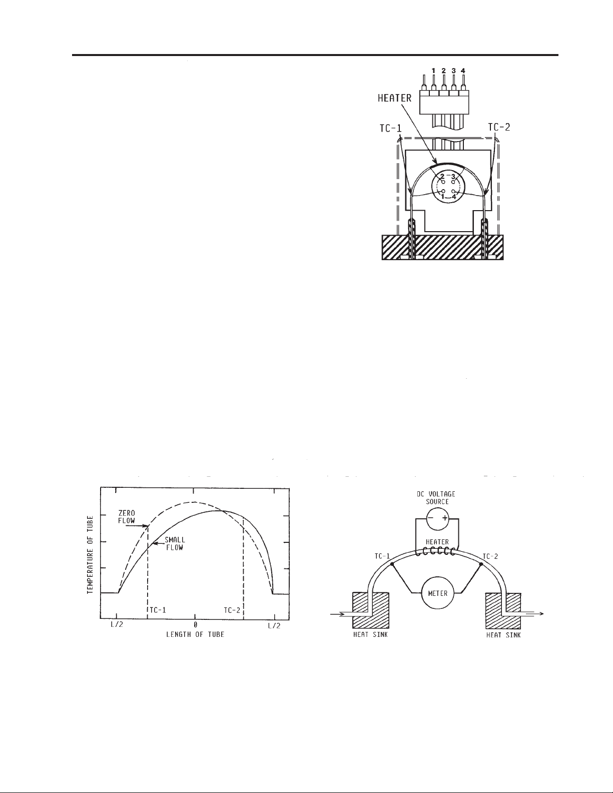
The Hastings Model HFM Mass Flowmeter operates on a unique thermal electric principle
whereby a metallic capillary tube is heated uniformly by a resistance winding attached to the mid-
point of the capillary (see Figure 3.1). Thermocouples TC-1 and TC-2 are welded at equal distances
from the mid-point and develop equal outputs at zero flow.
When flow occurs through the tubing, heat is transferred from the tube to the gas on the inlet side, and
from the gas back to the tube on the outlet side creating an asymmetrical temperature distribution (see
Figure 3.2). The thermocouples sense this decrease and increase in the capillary tube temperature, and
produce a millivolt output signal proportional to that change.
Fig.3.2Fig.3.2
Fig.3.2
Fig.3.2Fig.3.2
126B - PAGE 9
Fig.3.3Fig.3.3
Fig.3.3
Fig.3.3Fig.3.3

For a constant power input, the differential thermocouple output is a function of the mass flow rate and
the heat capacity of the gas. Since the heat capacity of many gases is relatively constant over wide
ranges of temperature and pressure, the flowmeter may be calibrated directly in
gases. Changes in gas composition usually only require application of a simple multiplier to the air
calibration to account for the difference in heat capacity , and thus the flowmeter is capable of
measuring a wide variety of gases.
3.3 Electronics3.3 Electronics
3.3 Electronics
3.3 Electronics3.3 Electronics
The Fast Response Model HFM uses a thermal flow sensor to measure flow through a capillary tube,
which is a fixed percentage of the total flow through the instrument. This sensor develops an output
signal proportional to flow which is approximately 0.8 mv full scale magnitude (see Figure 3.3). This
signal is amplified by the meter circuitry until it is 0-5.00 VDC. This 5 volt output is sent back to the
power supply and to the flowmeter circuitry, if applicable. At the pow er supply the 5 volt output is sent
to the terminals on the back and to the decoding circuitry in the display which converts it to a 3-1/2
digit output.
mass units for those
Fig.3.4Fig.3.4
Fig.3.4
Fig.3.4Fig.3.4
The Fast Response Model HFM uses additional electronics to achieve fast response characteristics by
amplifying the rate ofchange of the input signal, and adding it to the amplified input signal. The electronics are adjusted to provide response times of less than two seconds to 98% of a 0-100% step change
with less than 2% overshoot. The electronics also maintain the ouput signal above 5.00 VDC when the
flowrate exceeds the full scale flow of the flowmeter.
NONO
TE:TE:
NO
TE:
The output signal will continue to increase above 5.00 VDC as the flow rate exceeds full scale flow,
NONO
TE:TE:
however , the output above 5.00 VDC is non-linear and should not be used for flo w measurement.
3.4 Shunt3.4 Shunt
3.4 Shunt
3.4 Shunt3.4 Shunt
Higher measurement of flow rates is achieved by dividing the flow with a fixed ratio shunting arrangement, as is illustrated in Figure 3.4. This is accomplished by placing the measuring capillary tube parallel
with one or more dimensionally similarchannels, called a laminar flo w element (LFE). Therefore, the
sensor only needs to heat the gas passing through the capillary tube resulting in low power requirements, while retaining all the mass measuring characteristics.
The HFM-229 has two possible shunts. The lo w range shunt consists of tubes inserted into a cylindrical
base. This shunt is adjustable for ranges from 0-10 sccm to 0-250 sccm (see Figure 3.5). The higher
range shunt consists of a corrugated stainless steel ribbon wound into a coil and fused. The higher range
shunt is adjustable from 0-0.3 slpm to 0-30 slpm ranges(Figure 3.6).
Fig.3.5Fig.3.5
Fig.3.5
Fig.3.5Fig.3.5
126B - PAGE 10
Fig.3.6Fig.3.6
Fig.3.6
Fig.3.6Fig.3.6

The HFM-230 uses a shunt which is acorrugated and fused shunt similar to the shunt used in the
lower flow range instruments (see Figure 3.7). This highest range shunt is adjustable from 0- 50 slpm
to 0-500 slpm.
The HFM-229B Series uses an external laminar flow element instead of an internal shunt, because the
necessary size for the element exceeds the body size of the flowmeter. This laminar flow element is
made of a corrugated and fused stainless steel ribbon similar to the one used in the
Model HFM-230.
Fig.3.7Fig.3.7
Fig.3.7
Fig.3.7Fig.3.7
126B - PAGE 11

126B - PAGE 12

4.0 MAINTENANCE
4.1 Introduction:4.1 Introduction:
4.1 Introduction:
4.1 Introduction:4.1 Introduction:
This section contains service and calibration information. Some portions of the instrument are delicate.
Use extreme care when servicing the flowmeter. The potentiometer positions and the electrical compo-
nents referred to in the troubleshooting section can be found in Section 6.0 on the electrical component
layout drawing.
4.2 4.2
AuthorAuthor
4.2
Author
4.2 4.2
AuthorAuthor
With proper care in installation and use, the flowmeter will require little or no maintenance. If mainte-
nance does become necessary, most of the instrument can be cleaned or repaired in the field. Some
procedures may require recalibration. Do not attempt these procedures unless facilities are available.
Entry into the sensor or tampering with the printed circuit board will void warranty . Do not perform
repairs on these assemblies while unit is still under warranty.
4.3 4.3
Adjustments:Adjustments:
4.3
Adjustments:
4.3 4.3
Adjustments:Adjustments:
4.3.1 Calibration Procedure4.3.1 Calibration Procedure
4.3.1 Calibration Procedure
4.3.1 Calibration Procedure4.3.1 Calibration Procedure
1.1.
1.
Connect power cable to D connector as specified in Section 2.5. Allo w instrument to warm up for
1.1.
30 minutes with all flow shut off.
2.2.
2.
Set ZERO potentiometer for 0.000 VDC output at pin 6 on the D connector or flow output pin on
2.2.
the rear of the Hastings Pow er Supply .
3.3.
3.
T urn on air supply to inlet of instrument. Adjust flow rate to 100% according to flo w reference.
3.3.
4.4.
4.
Adjust SPAN pot until the flo wmeter
4.4.
indicates full scale flow (5.000 VDC).
NOTE: P erform this step only if a
calibrated reference flowmeter is available.
ized Maintenance:ized Maintenance:
ized Maintenance:
ized Maintenance:ized Maintenance:
5. 5.
5. Record flowmeter and flow reference
5. 5.
outputs for flow rates of 20%, 40%, 60%,
80%, and 100%.
4.3.2 Response 4.3.2 Response
4.3.2 Response
4.3.2 Response 4.3.2 Response
Readjustments of the fast response
circuit should not be necessary unless
changes in the range or sensor have
been performed. The flowmeter should
be calibrated before setting the response
time.
IMPORTANT: Response time cannot
be tested with a simple shutoff valve.
Pressure builds up behind the valve, and when opened creates a surge flow in excess of the calibrated flow rate.
What must be used is a two-way valve or a fitting which can be quickly connected and provide a leak-free seal to
the flowmeter inlet. The reference flow is vented to atmosphere, and switches through the flowmeter when the
valve is operated or fitting is connected. The valve or fitting should be close coupled to the flo wmeter inlet to
reduce pneumatic time delays. The response pot is not accessible from the exterior of the flowmeter. The cover
must be removed to make any adjustments. See Fig. 4.1.
Using a voltmeter, strip chart recorder, or oscilloscope connected to the flow output voltage, switch flow through
the flowmeter and observe output voltage. Adjust response pot to increase or decrease response time. The
response pot is a single turn pot and a small pot adjustment produces a large response time change. Remove flow
from flowmeter and allow output voltage to reach zero volts. Repeat test until response time is set.
Time Time
Time
Time Time
AdjustmentsAdjustments
Adjustments
AdjustmentsAdjustments
Fig.4.1Fig.4.1
Fig.4.1
Fig.4.1Fig.4.1
4.3.34.3.3
4.3.3
4.3.34.3.3
Periodically , during normal operation, the ZER O should be checked and adjusted when required.
Miscellaneous Miscellaneous
Miscellaneous
Miscellaneous Miscellaneous
AdjustmentsAdjustments
Adjustments
AdjustmentsAdjustments
126B - PAGE 13

4.4 End Cap Removal4.4 End Cap Removal
4.4 End Cap Removal
4.4 End Cap Removal4.4 End Cap Removal
The end cap on the inlet side must be removed to gain access to the filter or shunt assembly. First shut
off the supply of gas to the instrument. Disconnect the Swagelok fitting on the inlet and outlet sides of
the instrument. Remove the four hex bolts holding the end cap to the instrument (see Figure 4.2).
Carefully remove the end cap, filter, wave spring and shunt, noting their order and proper orientation.
NOTE: The Model HFM-230 does not include a wave spring. The shunt can be severely damaged if
dropped. Examine the filter and shunt. If either is dirty or blocked, clean or replace as applicable.
Reassembly is the reverse of the removal procedure.
Fig.4.2Fig.4.2
Fig.4.2
Fig.4.2Fig.4.2
NO TE: When reinstalling the small range shunt, ensure that corrugated side is down.
4.5 Range Changes4.5 Range Changes
4.5 Range Changes
4.5 Range Changes4.5 Range Changes
Remove end cap and shunt assembly per Section 4.4 abov e. The 0-10 sccm to 0-300 sccm range
shunt has tubes, while the medium range shunt is built from a coil of corrugated stainless steel foil. The
medium range shunt has a disk assembly with two large, one medium, and one small hole. To change
ranges, the disc on the inlet of the shunt should be loosened, turned and retightened to expose the
number of holes or tubes as listed below for the range desired.
SIZESIZE
SIZE
SIZESIZE
SMALL .......................................... 0-10 sccm............................................................................... 0 tubes
........................................................ 0-30 sccm................................................................................ 1 tube
........................................................ 0-50 sccm...............................................................................2 tubes
........................................................ 0-100 sccm.............................................................................4 tubes
........................................................ 0-250 sccm...........................................................................10 tubes
MEDIUM....................................... 0-.3 slpm ...................................................................... smallest hole
........................................................ 0-1 slpm ........................................................................ medium hole
........................................................ 0-3 slpm .......................................................... 1 large and small hole
........................................................ 0-5 slpm ................................................................... both large holes
........................................................ 0-10 slpm ........................................................................ half-washer
........................................................ 0-30 slpm .................................................................washer removed
LARGE........................................... 0-50 slpm ................................................................................ 1 hole
........................................................ 0-100 slpm ............................................................................. 2 holes
........................................................ 0-150...............................................................................slpm3 holes
........................................................ 0-300................................................................ slpmwasher removed
........................................................ 0-500............................................................... slpm washer removed
NONO
TETE
NO
TE: These ranges are for Air a t Standard Temperature and Pressure.
NONO
TETE
RANGE RANGE
RANGE
RANGE RANGE
SHUNT SETUPSHUNT SETUP
SHUNT SETUP
SHUNT SETUPSHUNT SETUP
126B - PAGE 14

4.6 Printed Circuit Board4.6 Printed Circuit Board
4.6 Printed Circuit Board
4.6 Printed Circuit Board4.6 Printed Circuit Board
ReplacementReplacement
Replacement
ReplacementReplacement
In the unlikely event that the PC board
fails, it is easily removed from the instrument and replaced with a spare to minimize
instrument downtime. Replacement of the
PC board will require the instrument to be
recalibrated per Section 4.3.1.Unplug the
power cable from the top of the transducer.
Remove the two screws on the side of the
cover. Lift off the cover and unplug the
four-wire sensor plug noting the orientation
prior to removal.
holds the PC board to the sensor. T roubleshoot or replace as applicable. Installation is
the reverse of the above procedure.
Recalibrate if any components were
changed or if any potentiometers were
adjusted.
4.7 Sensor Replacement4.7 Sensor Replacement
4.7 Sensor Replacement
4.7 Sensor Replacement4.7 Sensor Replacement
Remove the screw that
Fig.4.3Fig.4.3
Fig.4.3
Fig.4.3Fig.4.3
If the sensor fails or becomes plugged it can be
Section 4.6 above. Remove the three bolts holding the sensor to the instrument base. Remove the
sensor from the base noting the two O-rings (Parker 2-005, V884-75) between the sensor and the base.
See Figure 4.3. If the sensor is plugged it can be cleaned by running a fine wire (approximately 0.008"
diameter) through the tube. If sensor needs replacement, obtain another from the factory and install it.
Ensure that O-rings are clean and intact. Install O-rings on seating surface, then carefully place sensor
over O-rings, and tighten do wn the three screws evenly . Replacement of sensor will require recalibration
per Section 4.3.1.
4.8 4.8
TT
4.8
4.8 4.8
SYMPTSYMPT
SYMPT
SYMPTSYMPT
CACA
CA
CACA
AA
CTION:CTION:
A
CTION: Turn off pow er supply for a few seconds, then turn back on. If this prov es ineffective,
AA
CTION:CTION:
disconnect the unit from the power supply . If power supply displa y does not return to zero, then a
regulator chip in the power supply is probably burned out.
Check supply voltages and replace faulty regulator. If display
returns to zero after disconnecting the power supply from the
unit there is a short in the unit to ground. Check capacitors C11
& C13 first.
SYMPTOM:SYMPTOM:
SYMPTOM: Output of unit is proportional to flow but
SYMPTOM:SYMPTOM:
extremely small and not correctable by span pot.
roubleshootingroubleshooting
T
roubleshooting
TT
roubleshootingroubleshooting
OM:OM:
OM: Output reads 40% of flow with no flow. Zero pot has no effect.
OM:OM:
USE:USE:
USE: Pow er supply locked up or shorted out.
USE:USE:
removed.
Remove the cover and the PC board per
CAUSE: CAUSE:
CAUSE: Sensor is not being heated.
CAUSE: CAUSE:
AA
CTION:CTION:
A
CTION: Unplug sensor from PC board (Fig. 4.3). Pins on sensor are
AA
CTION:CTION:
numbered from left to right. Begin counting with second pin from left (see Fig.
4.4). Check the resistance between pins 2 & 3 of the sensor. This will read between
2450 & 2550. Check the resistance between pins 1 & 4 of the sensor . This should
read approximately 2.3 ohms. If this reads open circuit, sensor was probably
plugged into PC board improperly and one of the thermocouples has been
destroyed. Replace sensor. Check the resistance between pin 2 and the base of the
sensor. This should be an open circuit. Repeat for pin 3 and the base. If resistance
readings are correct but sensor is not indicating flow, the sensor is probably plugged;
clean or replace as applicable.
126B - PAGE 15
Fig.4.4Fig.4.4
Fig.4.4
Fig.4.4Fig.4.4

SYMPTOM: SYMPTOM:
SYMPTOM: Sensor has proper resistance readings, but little or no output with flow .
SYMPTOM: SYMPTOM:
CAUSE:CAUSE:
CAUSE: Plugged sensor.
CAUSE:CAUSE:
AA
CTION:CTION:
A
CTION: Shut off gas supply and power supply. Remove cover and PC board from unit. Remove
AA
CTION:CTION:
sensor assembly and examine. If sensor has evidence of plugging, clean or replace as applicable.
SYMPTSYMPT
SYMPT
SYMPTSYMPT
OM:OM:
OM: Flowmeter reads other than 0.00 VDC with no flow , or there is a small flow when
OM:OM:
flowmeter reads 0.00 VDC.
CACA
USE:USE:
CA
USE: ZERO potentiometer is out of adjustment.
CACA
USE:USE:
AA
CTION:CTION:
A
CTION: Shut off all flow. Adjust ZER O potentiometer until output reads 0.00 VDC.
AA
CTION:CTION:
SYMPTOM:SYMPTOM:
SYMPTOM: Flowmeter out of calibration and non-linear.
SYMPTOM:SYMPTOM:
CAUSE:CAUSE:
CAUSE: Leaks in gas inlet or outlet fittings.
CAUSE:CAUSE:
AA
CTION:CTION:
A
CTION: Check all fittings for leaks by placing soap solution on all fittings between gas supply and
AA
CTION:CTION:
final destination of gas. Check flowmeter for leaks. Replace “O” rings if required or recalibrate as
necessary.
126B - PAGE 16

5.0 REPLACEMENT PARTS
The following is a list of the available replacement parts and their factory stock numbers. The HFM229, HFM-229B, HFM-200, HFM-200B, and the HFC-202 shunts and filter discs are interchangeable. The HFM-230, HFM-201, and the HFC-203 shunts and filter discs are also interchangeable. The
same sensor module is used on all of the above models.
STST
OCK NOOCK NO
ST
OCK NO
STST
OCK NOOCK NO
81-102L......... LO W RANGE SHUNT.....................................................10, 30, 50, 100, 250 SCCM
81-102H ........ MED RANGE SHUNT ....................................................... 0.3, 1, 3, 5, 10, 30 SLPM
81-102B......... HIGH RANGE SHUNT ............................................... 50, 100, 150, 300, 500 SLPM
65-140E......... LFE Model LS-2, 2.0" NPTM ................................................................. 0-750 SLPM
65-140G ........ LFE Model LS-3, 3.0" NPTM ............................................................... 0-1500 SLPM
65-140J .......... LFE Model LS-4F, 4.0" Flange............................................................... 0-3000 SLPM
65-140K ........LFE Model LS-6F, 6.0" Flange............................................................... 0-6000 SLPM
65-140L......... LFE Model LS-8F, 8.0" Flange............................................................ 0-15,000 SLPM
..
DESCRIPTIONDESCRIPTION
.
DESCRIPTION
..
DESCRIPTIONDESCRIPTION
AIR RANGEAIR RANGE
AIR RANGE
AIR RANGEAIR RANGE
39-02-003......SMALL FIL TER DISC................................................. HFM-229, HFM-229B, AND
39-02-002...... LARGE FIL TER DISC ...................................................... HFM-230 AND HFC-203
81-105 ........... SENSOR MODULE ...........................................................................ALL MODELS
65-595 ........... FAST RESPONSE HFM ELECTRONICS CARD ...................... D CONNECTOR
81-115 .....................................................................VITON O-RING KIT FOR HFM-200 and 200B
81-116 .....................................................................................VITON O-RING KIT FOR HFM-201
81-146 .............................................................. KALREZ
TM
O-RING KIT FOR HFM-200 and 200B
81-147 .............................................................................. KALREZTM O-RING KIT FOR HFM-201
81-150 ............................................................ NEOPRENE O-RING KIT FOR HFM-200 and 200B
81-151 ............................................................................ NEOPRENE O-RING KIT FOR HFM-201
NONO
TETE
NO
TE: Ranges listed are for same standard temperature and pressure.
NONO
TETE
To place an order or to obtain information concerning replacement parts, contact the factory or our
local manufacturer’s representativ e in your area. See below , or this manual’ s last page for the address or
phone number. When ordering, include the following information:
HFC-202
• Instrument model number
• Part description
• Hastings part number
126B - PAGE 17

126B - PAGE 18

6.0 Warranty and Repair
WW
arar
ranty Pranty P
W
ar
ranty P
WW
arar
ranty Pranty P
Hastings Instruments warrants this product for a period of one year from the date of shipment to
be free from defects in material and workmanship. This warranty does not apply to defects or
failures resulting from unauthorized modification, misuse or mishandling of the product. This
warranty does not apply to batteries or other expendable parts, nor to damage caused by leaking
batteries or any similar occurrence. This warranty does not apply to any instrument which has had
a tamper seal removed or broken.
This warranty is in lieu of all other warranties, expressed or implied, including any implied warranty
as to fitness for a particular use. Hastings Instruments shall not be liable for any indirect or consequential damages.
Hastings Instruments will, at its option, repair, replace or refund the selling price of the product if
Hastings Instruments determines, in good faith, that it is defective in materials or workmanship
during the warranty period. Defective instruments should be returned to Hastings Instruments
together with a written statement of the problem and a Return Material Authorization (RMA)
number. Please consult the factory for your RMA number before returning any product for repair.
olicolic
olic
olicolic
yy
y
yy
Non-WNon-W
Non-W
Non-WNon-W
Any product returned for a non-warranty repair must be accompanied by a purchase order, RMA
form and a written description of the problem with the instrument. If the repair cost is higher, you
will be contacted for authorization before we proceed with any repairs. If you then choose not to
have the product repaired, a minimum will be charged to cover the processing and inspection.
Please consult the factory for your RMA number before returning any product for repair.
arar
ranty Repair Pranty Repair P
ar
ranty Repair P
arar
ranty Repair Pranty Repair P
TELED YNE HASTINGS
804 NEWCOMBE AVENUE
HAMPTON, VIRGINIA 23669 U .S.A.
A TTENTION: REP AIR DEP AR TMENT
TELEPHONE (757) 723-6531
FA X (757) 723-3925
olicolic
olic
olicolic
yy
y
yy
1-800-950-2468
126B - PAGE 19

126B - PAGE 20

7.0 Diagrams and Drawings
126B - PAGE 21

PC-810 Assembly
(Information from Hastings drawing 30837 rev. F)
126B - PAGE 22

PC-810 Schematic
(Information from Hastings drawing 30837 rev. F)
126B - PAGE 23

126B - PAGE 24

126B - PAGE 25

126B - PAGE 26

126B - PAGE 27

126B - PAGE 28
 Loading...