

Page 1
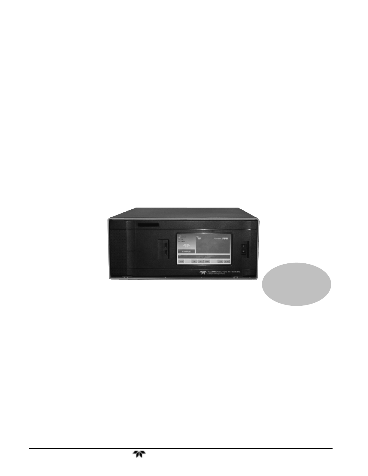
MODEL GFC 7000TA
CARBON DIOXIDE ANALYZER
Operation Manual
Also supports operation of:
GFC 7000T CO2 Analyzer
(when used in conjunction with GFC 7000T Addendum, PN 07273)
P/N M07272
DATE 06/04/13
TELEDYNE ELECTRONIC TECHNOLOGIES
Analytical Instruments
16830 Chestnut Street
City of Industry, CA 91748
Telephone: (626) 934-1500
Fax: (626) 961-2538
Web: www.teledyne-ai.com
Teledyne Analytical Instruments
Page 2

Model GFC7000TA Carbon Dioxide Analyzer
Copyright © 2013 Teledyne Analytical Instruments
All Rights Reserved. No part of this manual may be reproduced, transmitted, transcribed, stored in a retrieval
system, or translated into any other language or computer language in whole or in part, in any form or by any
means, whether it be electronic, mechanical, magnetic, optical, manual, or otherwise, without the prior written
consent of Teledyne Analytical Instruments, 16830 Chestnut Street, City of Industry, CA 91748.
Warranty
This equipment is sold subject to the mutual agreement that it is warranted by us free from defects of material
and of construction, and that our liability shall be limited to replacing or repairing at our factory (without
charge, except for transportation), or at customer plant at our option, any material or construction in which
defects become apparent within one year from the date of shipment, except in cases where quotations or
acknowledgements provide for a shorter period. Components manufactured by others bear the warranty of their
manufacturer. This warranty does not cover defects caused by wear, accident, misuse, neglect or repairs other
than those performed by Teledyne or an authorized service center. We assume no liability for direct or indirect
damages of any kind and the purchaser by the acceptance of the equipment will assume all liability for any
damage which may result from its use or misuse.
We reserve the right to employ any suitable material in the manufacture of our apparatus, and to make any
alterations in the dimensions, shape or weight of any parts, in so far as such alterations do not adversely affect
our warranty.
Important Notice
This instrument provides measurement readings to its user, and serves as a tool by which valuable data can be
gathered. The information provided by the instrument may assist the user in eliminating potential hazards caused
by his process; however, it is essential that all personnel involved in the use of the instrume nt o r its int e rfac e be
properly trained in the process being measured, as well as all instrumentation related to it.
The safety of personnel is ultimately the responsibility of those who control process conditions. While this
instrument may be able to provide early warning of imminent danger, it has no control over process conditions,
and it can be misused. In particular, any alarm or control systems installed must be tested and understood, both
as to how they operate and as to how they can be defeated. Any safeguards required such as locks, labels, or
redundancy, must be provided by the user or specifically requested of Teledyne at the time the order is placed.
Therefore, the purchaser must be aware of the hazardous process conditions. The purchaser is responsible for
the training of personnel, for providing hazard warning methods and instrumentation per the appropriate
standards, and for ensuring that hazard warning devices and instrumentation are maintained and operated
properly.
Teledyne Analytical Instruments, the manufacturer of this instrument, cannot accept responsibility for
conditions beyond its knowledge and control. No statement expressed or implied by this document or any
information disseminated by the manufacturer or its agents, is to be construed as a warranty of adequate safety
control under the user’s process conditions.
Trademarks
All trademarks, registered trademarks, brand names or product names appearing in this document are the
property of their respective owners and are used herein for identification purposes only.
Teledyne Analytical Instruments ii
Page 3

Model GFC7000TA Carbon Dioxide Analyzer
This page intentionally left blank.
Teledyne Analytical Instruments iii
Page 4

Page 5
Safety Messages Model GFC7000TA Carbon Dioxide Analyzer
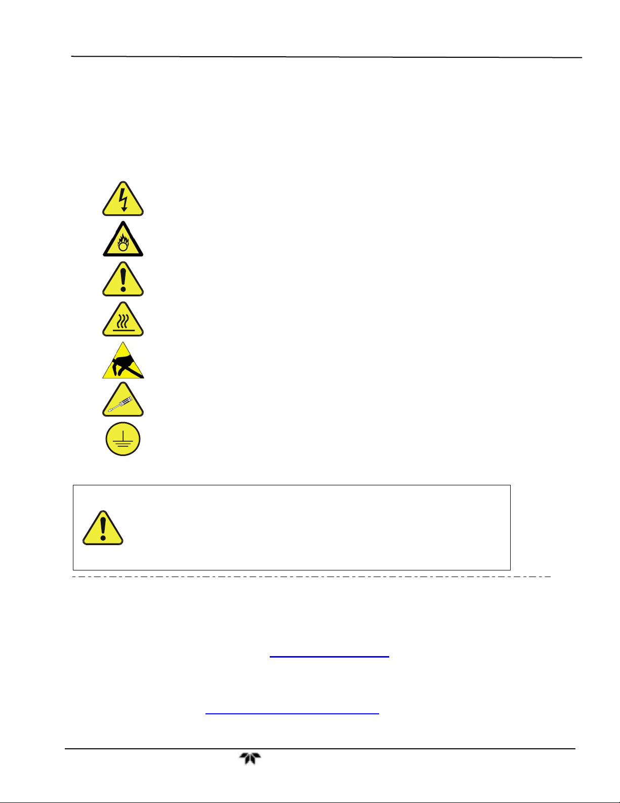
SAFETY MESSAGES
Important safety messages are provided throughout this manual for the purpose of avoiding personal
injury or instrument damage. Please read these messages carefully. Each safety message is associated
with a safety alert symbol, and are placed throughout this manual; the safety symbols are also located
inside the instrument.
descriptions of which are as follows:
It is imperative that you pay close attention to these messages, the
WARNING: Electrical Shock Hazard
HAZARD: Strong oxidizer
GENERAL WARNING/CAUTION: Read the accompanying message for
specific information.
CAUTION: Hot Surface Warning
Do Not Touch: Touching some parts of the instrument without
protection or proper tools could result in damage to the part(s) and/or the
instrument.
Technician Symbol: All operations marked with this symbol are to be
performed by qualified maintenance personnel only.
Electrical Ground: This symbol inside the instrument marks the central
safety grounding point for the instrument.
CAUTION
This instrument should only be used for the purpose and in the manner
described in this manual. If you use this instrument in a manner other than
that for which it was intended, unpredictable behavior could ensue with
possible hazardous consequences.
NEVER use any gas analyzer to sample combustible gas(es)!
Note: Technical Assistance regarding the use and maintenance of the GFC7001TA or
any other Teledyne product can be obtained by contacting Teledyne Customer
Service Department:
Phone: 888-789-8168
Email: ask_tai@teledyne.com
or by accessing various service options on our website at
http://www.teledyne-ai.com/
Teledyne Analytical Instruments v
Page 6
Safety Messages Model GFC7000TA Carbon Dioxide Analyzer
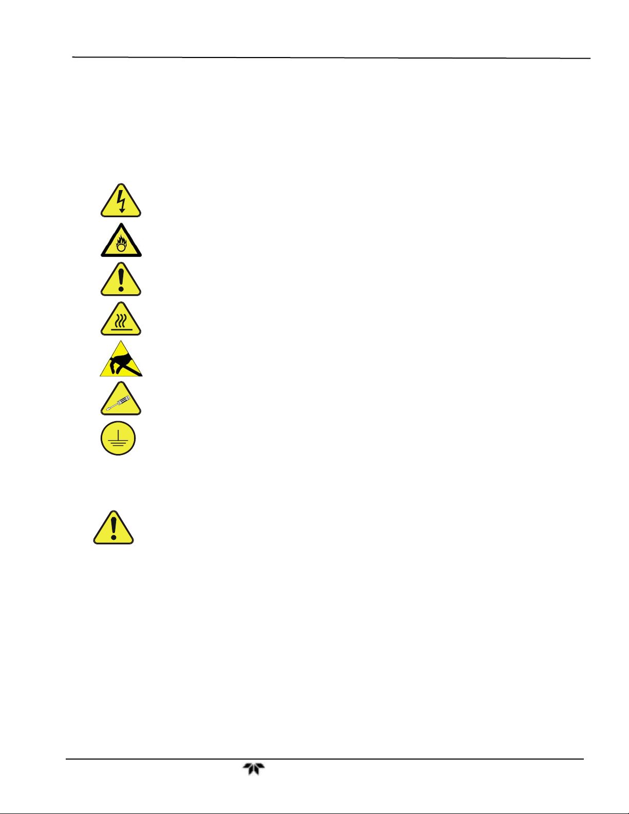
CONSIGNES DE SÉCURITÉ
Des consignes de sécurité importantes sont fournies tout au long du présent manuel dans le but d’éviter
des blessures corporelles ou d’endommager les instruments. Veuillez lire attentivement ces consignes.
Chaque consigne de sécurité est représentée par un pictogramme d’alerte de sécurité; ces pictogrammes
se retrouvent dans ce manuel et à l’intérieur des instruments. Les symboles correspondent aux
consignes suivantes :
AVERTISSEMENT : Risque de choc électrique
DANGER : Oxydant puissant
AVERTISSEMENT GÉNÉRAL / MISE EN GARDE : Lire la consigne
complémentaire pour des renseignements spécifiques
MISE EN GARDE : Surface chaude
Ne pas toucher : Toucher à certaines parties de l’instrument sans protection ou
sans les outils appropriés pourrait entraîner des dommages aux pièces ou à
l’instrument.
Pictogramme « technicien » : Toutes les opérations portant ce symbole doivent
être effectuées uniquement par du personnel de maintenance qualifié.
Mise à la terre : Ce symbole à l’intérieur de l’instrument détermine le point central
de la mise à la terre sécuritaire de l’instrument.
MISE EN GARDE
Cet instrument doit être utilisé aux fins décrites et de la manière décrite dans
ce manuel. Si vous utilisez cet instrument d’une autre manière que celle pour
laquelle il a été prévu, l’instrument pourrait se comporter de façon imprévisible
et entraîner des conséquences dangereuses.
NE JAMAIS utiliser un analyseur de gaz pour échantillonner des gaz
combustibles!
Teledyne Analytical Instruments vi
Page 7

Safety Messages Model GFC7000TA Carbon Dioxide Analyzer
This page intentionally left blank.
Teledyne Analytical Instruments vii
Page 8

Page 9
Manual Information Model GFC7000TA Carbon Dioxide Analyzer
ABOUT THIS MANUAL
This manual, PN 07272, provides operation instructions for the GFC 7000TA Analyzer,
and supports operation of the Model GFC 7000T (when used in conjunction with the
GFC 7000T Addendum, PN 07273). This manual is comprised of multiple documents as
listed below.
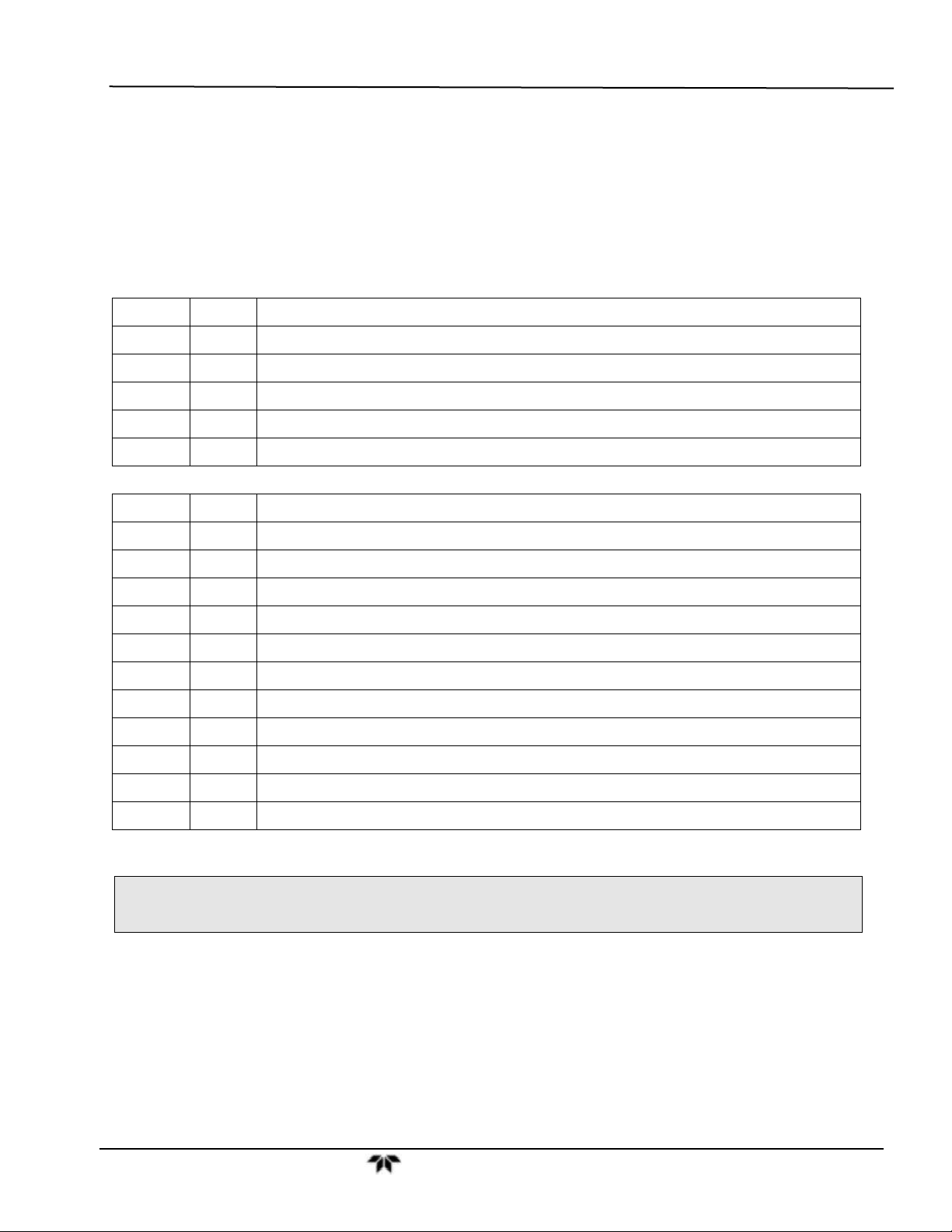
Part No. Rev Name/Description
07272 A GFC 7000TA Carbon Dioxide Analyzer Operation Manual
05233 H Menu trees and software documentation (inserted as Appendix A of this manual)
06879
04411 M Recommended Spare Parts Stocking Levels
05235 C Repair Request Questionnaire (inserted as Appendix C of this manual)
0691201 B Interconnect Wire List (located in Appendix D of this manual)
069121 B Interconnect Wiring Diagram (located in Appendix D of this manual)
03297 K PCA, 03296, IR Photodetector Preamp and Sync Demodulator
03632 A PCA, 03631, 0-20mA driver
04003 N PCA, 04003, Pressure/Flow Transducer Interface
04089 A PCA, 04088, Opto Pickup Interface
04136 B PCA, 04135 Rev A, Relay
04468 B PCA, 04467, Analog Output Series Res
05803 B SCH, PCA 05802, MOTHERBOARD, GEN-5
06698 D SCH, PCA 06697, INTRFC, LCD TCH SCRN,
06882 B SCH, LVDS TRANSMITTER BOARD
06731 A SCH, AUXILLIARY-I/O BOARD
1/4/2011
Interconnects and Schematics included in Appendix D of this manual
Spare Parts List (located in Appendix B, this manual)
NOTE
Please read this manual in its entirety before operating the instrument.
Teledyne Analytical Instruments ix
Page 10

Manual Information Model GFC7000TA Carbon Dioxide Analyzer
2010, T360 Manual, PN0 Rev A, DCN
Document PN Rev DCN Change Summary
For the purpose of capturing this manual’s construct at its initial release, the following list documents the
current Rev of each part comprising Rev A of this manual. Any future changes to this manual will be
recorded in this Revision History section, most recent changes at the top. Their new Rev letters will be
updated in the preceding About This Manual section:
0xxxx
X Initial Release
This page intentionally left blank.
Teledyne Analytical Instruments x
Page 11

Table of Contents Model GFC7000TA Carbon Dioxide Analyzer
TABLE OF CONTENTS
SAFETY MESSAGES ............................................................................................................................................... v
CONSIGNES DE SÉCURITÉ ................................................................................................................................... vi
ABOUT this MANUAL .............................................................................................................................................. ix
TABLE OF CONTENTS ........................................................................................................................................... xi
1. INTRODUCTION ........................................................................................................................................................ 1
1.1. Features ............................................................................................................................................................. 1
1.2. Using This Manual .............................................................................................................................................. 1
2. SPECIFICATIONS AND APPROVALS ..................................................................................................................... 5
2.1. Specifications ..................................................................................................................................................... 5
2.2. CE Mark Compliance ......................................................................................................................................... 7
3. GETTING STARTED ................................................................................................................................................. 9
3.1. Unpacking and Initial Set Up .............................................................................................................................. 9
3.2. Front Panel ....................................................................................................................................................... 11
3.3. Rear Panel ....................................................................................................................................................... 15
3.4. Internal Layout ................................................................................................................................................. 17
3.5. Electrical Connections ...................................................................................................................................... 19
3.5.1. Power Connection .................................................................................................................................... 20
3.5.2. Connecting Analog Inputs (Option 64) ...................................................................................................... 20
3.5.3. Connecting Analog Outputs ...................................................................................................................... 21
3.5.4. Connecting the Status Outputs ................................................................................................................. 23
3.5.5. Connecting the Control Inputs .................................................................................................................. 24
3.5.6. Connecting the Communications Interfaces ............................................................................................. 25
3.6. Pneumatic Connections ................................................................................................................................... 25
3.6.1. Basic Pneumatic Connections .................................................................................................................. 26
3.6.2. Connections with Internal Valve Options Installed .................................................................................... 30
3.6.3. Pneumatic Connections in Multipoint Calibration Applications.................................................................. 32
3.6.4. Setting the Internal Purge Air Pressure .................................................................................................... 32
3.7. Initial Operation ................................................................................................................................................ 33
3.7.1. Startup ...................................................................................................................................................... 33
3.7.2. Warm Up................................................................................................................................................... 34
3.7.3. Warning Messages ................................................................................................................................... 34
3.7.4. Functional Check ...................................................................................................................................... 36
3.8. Initial Calibration Procedure ............................................................................................................................. 37
3.8.1. Initial O
4. FREQUENTLY ASKED QUESTIONS ..................................................................................................................... 45
4.1. FAQ’s ............................................................................................................................................................... 45
4.2. Glossary ........................................................................................................................................................... 46
5. OPTIONAL HARDWARE AND SOFTWARE .......................................................................................................... 51
5.1. Rack Mount Kits (Options 20A, 20B, 21 and 23) .............................................................................................. 51
5.2. Current Loop Analog Outputs (Option 41) ........................................................................................................ 51
5.2.1. Converting Current Loop Analog Outputs to Standard Voltage Outputs ................................................... 52
5.3. Expendable Kits (Options 42C, 42D and 43) .................................................................................................... 53
5.4. Calibration Valves Options ............................................................................................................................... 54
5.4.1. Ambient Zero/Pressurized Span Valve ..................................................................................................... 54
5.4.2. Ambient Zero/Ambient Span Valve ........................................................................................................... 55
5.5. Communication Options ................................................................................................................................... 57
5.5.1. Communications Cables ........................................................................................................................... 57
5.5.2. RS-232 Multidrop (Option 62) ................................................................................................................... 57
5.6. Oxygen Sensor (OPT 65) ................................................................................................................................. 58
5.6.1. Theory of Operation .................................................................................................................................. 58
5.7. Special Features .............................................................................................................................................. 61
5.7.1. Dilution Ratio Option ................................................................................................................................. 61
5.7.2. Maintenance Mode Switch ........................................................................................................................ 61
5.7.3. Second Language Switch ......................................................................................................................... 61
6. OPERATING INSTRUCTIONS ................................................................................................................................ 63
6.1. Overview of Operating modes .......................................................................................................................... 63
6.2. Sample Mode ................................................................................................................................................... 64
Sensor Calibration Procedure .................................................................................................... 40
2
Teledyne Analytical Instruments xi
Page 12

Table of Contents Model GFC7000TA Carbon Dioxide Analyzer
6.2.1. Test Functions .......................................................................................................................................... 65
6.2.2. Warning Messages ................................................................................................................................... 67
6.3. Calibration Mode .............................................................................................................................................. 68
6.4. SETUP MODE.................................................................................................................................................. 69
6.5. SETUP CFG: Viewing the Analyzer’s Configuration Information ................................................................. 70
6.6. SETUP ACAL: Automatic Calibration .......................................................................................................... 70
6.7. SETUP DAS: Using the Data Acquisition System (DAS) ............................................................................. 71
6.7.1. DAS Structure ........................................................................................................................................... 72
6.7.2. Default DAS Channels .............................................................................................................................. 74
6.7.3. Remote DAS Configuration....................................................................................................................... 88
6.8. SETUP RNGE: Analog Output Reporting Range Configuration .................................................................. 89
6.8.1. Physical Range versus Analog Output Reporting Ranges ........................................................................ 90
6.8.2. Reporting Range Modes ........................................................................................................................... 90
6.8.3. Single Range Mode (SNGL) ..................................................................................................................... 92
6.8.4. Dual Range Mode (DUAL) ........................................................................................................................ 93
6.8.5. Auto Range Mode (AUTO)........................................................................................................................ 94
6.8.6. Range Units .............................................................................................................................................. 95
6.8.7. Dilution Ratio ............................................................................................................................................ 96
6.9. SETUP PASS: Password Feature ............................................................................................................... 97
6.10. SETUP CLK: Setting the Internal Time-of-Day Clock ................................................................................ 99
6.11. SETUP MORE COMM: Using the Analyzer’s Communication Ports .................................................... 101
6.11.1. Analyzer ID ........................................................................................................................................... 101
6.11.2. COM Port Default Settings .................................................................................................................... 102
6.11.3. RS-485 Configuration of COM2 ............................................................................................................ 105
6.11.4. DTE and DCE Communication ............................................................................................................. 105
6.11.5. COM Port Communication Modes ........................................................................................................ 106
6.11.6. Remote Access via the Ethernet ........................................................................................................... 108
6.11.7. Multidrop RS-232 Set Up ...................................................................................................................... 114
6.11.8. COM Port Baud Rate ............................................................................................................................ 116
6.11.9. COM Port Testing ................................................................................................................................. 117
6.12. SETUP MORE VARS: Internal Variables (VARS) ............................................................................... 118
6.13. SETUP MORE DIAG: Using the Diagnostics Functions ..................................................................... 120
6.13.1. Accessing the Diagnostic Features ....................................................................................................... 121
6.13.2. Signal I/O .............................................................................................................................................. 121
6.13.3. Analog Output Step Test ...................................................................................................................... 122
6.13.4. Analog I/O Configuration ...................................................................................................................... 123
6.13.5. Electric Test .......................................................................................................................................... 136
6.13.6. Dark Calibration Test ............................................................................................................................ 137
6.13.7. Pressure Calibration ............................................................................................................................. 138
6.13.8. Flow Calibration .................................................................................................................................... 139
6.13.9. Test Channel Output ............................................................................................................................. 140
6.14. SETUP MORE ALRM: Using the Gas Concentration Alarms ............................................................... 141
6.14.1. Setting the Concentration Alarm Limits ................................................................................................. 142
6.15. Remote Operation of the Analyzer ............................................................................................................... 142
6.15.1. Remote Operation Using the External Digital I/O .................................................................................. 142
6.15.2. Remote Operation Using the External Serial I/O .................................................................................. 146
6.15.3. Additional Communications Documentation ......................................................................................... 153
6.15.4. Using the GFC 7000TA with a Hessen Protocol Network ..................................................................... 153
7. CALIBRATION PROCEDURES ............................................................................................................................ 161
7.1. Before Calibration ........................................................................................................................................... 161
7.1.1. Zero Air and Span Gas ........................................................................................................................... 161
7.1.2. Calibration Gas Traceability .................................................................................................................... 162
7.1.3. Data Recording Devices ......................................................................................................................... 162
7.2. Manual Calibration without Zero/Span Valves ................................................................................................ 162
7.3. Manual Calibration Checks ............................................................................................................................ 165
7.4. Manual Calibration with Zero/Span Valves ..................................................................................................... 166
7.5. Manual Calibration Checks with Zero/Span Valves ........................................................................................ 171
7.5.1. Zero/Span Calibration on Auto Range or Dual Ranges .......................................................................... 172
7.5.2. Use of Zero/Span Valves with Remote Contact Closure ........................................................................ 173
7.6. Automatic Zero/Span Cal/Check (AutoCal) .................................................................................................... 173
7.6.1. AutoCal with Auto or Dual Reporting Ranges Modes Selected .............................................................. 176
7.7. Calibration Quality .......................................................................................................................................... 176
Teledyne Analytical Instruments xii
Page 13

Table of Contents Model GFC7000TA Carbon Dioxide Analyzer
8. MAINTENANCE SCHEDULE & PROCEDURES .................................................................................................. 179
8.1. Maintenance Schedule ................................................................................................................................... 179
8.2. Predicting Failures Using the Test Functions ................................................................................................. 183
8.3. Maintenance Procedures ............................................................................................................................... 184
8.3.1. Replacing the Sample Particulate Filter .................................................................................................. 184
8.3.2. Rebuilding the Sample Pump ................................................................................................................. 185
8.3.3. Performing Leak Checks ........................................................................................................................ 185
8.3.4. Performing a Sample Flow Check .......................................................................................................... 186
8.3.5. Cleaning the Optical Bench .................................................................................................................... 186
8.3.6. Cleaning Exterior Surfaces of the GFC 7000TA ..................................................................................... 186
9. THEORY OF OPERATION .................................................................................................................................... 187
9.1. Measurement Method .................................................................................................................................... 187
9.1.1. Beer’s Law .............................................................................................................................................. 187
9.1.2. Measurement Fundamentals .................................................................................................................. 187
9.1.3. Gas Filter Correlation .............................................................................................................................. 188
9.1.4. Interference and Signal to Noise Rejection ............................................................................................. 190
9.2. Pneumatic Operation ...................................................................................................................................... 193
9.2.1. Sample Gas Flow ................................................................................................................................... 194
9.2.2. Flow Rate Control ................................................................................................................................... 194
9.2.3. Purge Gas Pressure Control ................................................................................................................... 196
9.2.4. Particulate Filter ...................................................................................................................................... 196
9.2.5. Pneumatic Sensors ................................................................................................................................. 196
9.3. Electronic Operation ....................................................................................................................................... 197
9.3.1. Overview ................................................................................................................................................. 197
9.3.2. CPU ........................................................................................................................................................ 199
9.3.3. Optical Bench & GFC Wheel .................................................................................................................. 200
9.3.4. Synchronous Demodulator (Sync/Demod) Assembly ............................................................................. 202
9.3.5. Relay Board ............................................................................................................................................ 205
9.3.6. Mother Board .......................................................................................................................................... 207
2
9.3.7. I
9.3.8. Power Supply/ Circuit Breaker ................................................................................................................ 211
9.4. Front Panel Touchscreen/Display Interface ................................................................................................... 212
9.4.1. LVDS Transmitter Board ......................................................................................................................... 212
9.4.2. Front Panel Touchscreen/Display Interface PCA .................................................................................... 212
9.5. Software Operation ........................................................................................................................................ 213
9.5.1. Adaptive Filter ......................................................................................................................................... 213
9.5.2. Calibration - Slope and Offset ................................................................................................................. 214
9.5.3. Measurement Algorithm .......................................................................................................................... 214
9.5.4. Temperature and Pressure Compensation ............................................................................................. 215
9.5.5. Internal Data Acquisition System (DAS) ................................................................................................. 215
10. TROUBLESHOOTING & REPAIR PROCEDURES ............................................................................................ 217
10.1. General Troubleshooting Hints ..................................................................................................................... 217
10.1.1. Interpreting WARNING Messages ........................................................................................................ 218
10.1.2. Fault Diagnosis with TEST Functions ................................................................................................... 221
10.1.3. Using the Diagnostic Signal I/O Function ............................................................................................. 223
10.1.4. Internal Electronic Status LEDs ............................................................................................................ 224
10.2. Gas Flow Problems ...................................................................................................................................... 228
10.2.1. GFC 7000TA Internal Gas Flow Diagrams ........................................................................................... 229
10.2.2. Typical Sample Gas Flow Problems ..................................................................................................... 232
10.2.3. Poor or Stopped Flow of Purge Gas ..................................................................................................... 234
10.3. Calibration Problems .................................................................................................................................... 235
10.3.1. Miscalibrated ......................................................................................................................................... 235
10.3.2. Non-Repeatable Zero and Span ........................................................................................................... 236
10.3.3. Inability to Span – Touchscreen SPAN Button Not Visible ................................................................... 236
10.3.4. Inability to Zero – Touchscreen ZERO Button Not Visible .................................................................... 237
10.4. Other Performance Problems ....................................................................................................................... 238
10.4.1. Temperature Problems ......................................................................................................................... 238
10.4.2. Excessive Noise ................................................................................................................................... 240
10.5. Subsystem Checkout ................................................................................................................................... 241
10.5.1. AC Mains Configuration ........................................................................................................................ 241
10.5.2. DC Power Supply ................................................................................................................................. 241
10.5.3. I
C Data Bus ........................................................................................................................................... 210
2
C Bus .................................................................................................................................................. 242
Teledyne Analytical Instruments xiii
Page 14

Table of Contents Model GFC7000TA Carbon Dioxide Analyzer
10.5.4. Touchscreen Interface .......................................................................................................................... 242
10.5.5. LCD Display Module ............................................................................................................................. 242
10.5.6. Relay Board .......................................................................................................................................... 243
10.5.7. Sensor Assembly .................................................................................................................................. 243
10.5.8. Motherboard ......................................................................................................................................... 245
10.5.9. CPU ...................................................................................................................................................... 249
10.5.10. RS-232 Communications .................................................................................................................... 249
10.6. Repair Procedures ....................................................................................................................................... 251
10.6.1. Repairing Sample Flow Control Assembly ............................................................................................ 251
10.6.2. Removing/Replacing the GFC Wheel ................................................................................................... 252
10.6.3. Disk-On-Module Replacement Procedure ............................................................................................ 253
11. A PRIMER ON ELECTRO-STATIC DISCHARGE ............................................................................................... 255
11.1. How Static Charges are Created .................................................................................................................. 255
11.2. How Electro-Static Charges Cause Damage ............................................................................................... 256
11.3. Common Myths About ESD Damage ........................................................................................................... 257
11.4. Basic Principles of Static Control .................................................................................................................. 257
LIST OF APPENDICES
APPENDIX A - VERSION SPECIFIC SOFTWARE DOCUMENTATION, L.8
APPENDIX A-1: Models GFC 7000TA and GFC 7000E Software Menu Trees
APPENDIX A-2: GFC 7000 Series Setup Variables
APPENDIX A-3: GFC 7000 Series Warnings and Test Measurements
APPENDIX A-4: GFC 7000 Series Signal I/O Definitions
APPENDIX A-5: GFC 7000 Series DAS Triggering Events
APPENDIX A-6: GFC 7000 Series DAS Parameters
APPENDIX A-7: Terminal Command Designators
APPENDIX A-8: Terminal Key Assignments
APPENDIX A-9: GFC 7000 Series MODBUS Register
APPENDIX B - SPARE PARTS LIST and RECOMMENDED SPARES STOCKING LEVELS
APPENDIX C - REPAIR QUESTIONNAIRE
APPENDIX D - ELECTRONIC SCHEMATICS
Teledyne Analytical Instruments xiv
Page 15

Table of Contents Model GFC7000TA Carbon Dioxide Analyzer
LIST OF FIGURES
Figure 3-1: Front Panel Layout ...................................................................................................................... 11
Figure 3-2: Display Screen and Touch Control ............................................................................................. 12
Figure 3-3: Display/Touch Control Screen Mapped to Menu Charts ............................................................. 14
Figure 3-4: Rear Panel Layout ....................................................................................................................... 15
Figure 3-5: Internal Chassis Layout ............................................................................................................... 17
Figure 3-6: Optical Bench Layout .................................................................................................................. 18
Figure 3-7: GFC 7000TA Internal Gas Flow .................................................................................................. 19
Figure 3-8: Analog In Connector .................................................................................................................... 20
Figure 3-9: Pneumatic Connections–Basic Configuration–Using Bottled Span Gas .................................... 27
Figure 3-10: Pneumatic Connections–Basic Configuration–Using Gas Dilution Calibrator ............................ 27
Figure 3-11: Pneumatic Connections with Ambient Zero/Ambient Span Valves (OPT 50A) .......................... 30
Figure 3-12: Pneumatic Connections with Ambient Zero/Ambient Span Valves (Opt 50A) and
External Zero Air Scrubber .......................................................................................................... 30
Figure 3-13: Pneumatic Connections with Ambient Zero/Pressurized Span Valves (OPT 50B) .................... 31
Figure 3-14: Pneumatic Connections with Ambient Zero/Pressurized Span Valves (Opt 50B) and
External Zero Air Scrubber .......................................................................................................... 31
Figure 3-15: Example of Pneumatic Set up for Multipoint Calibration ............................................................. 32
Figure 3-16: O2 Sensor Calibration Set Up ..................................................................................................... 40
Figure 5-1: Current Loop Option Installed on the Motherboard ..................................................................... 52
Figure 5-2: Internal Pneumatic Flow – Ambient Zero/Pressurized Span Valves ........................................... 55
Figure 5-3: Internal Pneumatic Flow – Ambient Zero/Ambient Span ............................................................ 56
Figure 5-4: Multi-drop/LVDS PCA Seated on CPU ....................................................................................... 58
Figure 5-5: Oxygen Sensor - Principle of Operation ...................................................................................... 59
Figure 5-6: GFC 7000TA – Internal Pneumatics with O2 Sensor Option 65 ................................................. 60
Figure 6-1: Front Panel Display ..................................................................................................................... 63
Figure 6-2: Viewing TEST Functions ............................................................................................................. 66
Figure 6-3: Viewing and Clearing GFC 7000TA WARNING Messages ........................................................ 68
Figure 6-4: Default DAS Channels Setup ...................................................................................................... 75
Figure 6-5: APICOM User Interface for DAS Configuration .......................................................................... 88
Figure 6-6: Analog Output Connector Pin Out ............................................................................................... 89
Figure 6-7: Rear Panel Connector Pin-Outs for COM1 & COM2 in RS-232 Mode ..................................... 103
Figure 6-8: CPU Connector Pin-Outs for COM1 & COM2 in RS-232 Mode ............................................... 104
Figure 6-9: Multidrop/LVDS PCA Seated on CPU ....................................................................................... 114
Figure 6-10: RS232-Multidrop PCA Host/Analyzer Interconnect Diagram .................................................... 115
Figure 6-11: Setup for Calibrating Analog Voltage Outputs .......................................................................... 130
Figure 6-12: Setup for Calibrating Current Outputs ....................................................................................... 132
Figure 6-13: Status Output Connector ........................................................................................................... 143
Figure 6-14: Control Inputs ............................................................................................................................ 145
Figure 6-15: APICOM Remote Control Program Interface ............................................................................ 152
Figure 7-1: Pneumatic Connections–Basic Configuration–Using Bottled Span Gas .................................. 162
Figure 7-2: Pneumatic Connections–Basic Configuration–Using Gas Dilution Calibrator .......................... 163
Figure 7-3: Pneumatic Connections – Ambient Zero/Pressurized Span Valves ........................................ 166
Figure 7-4: Pneumatic Connections – Ambient Zero/Pressurized Span Valves and External Zero Air
Scrubber .................................................................................................................................... 167
Figure 7-5: Pneumatic Connections – Ambient Zero/Ambient Span Valves ............................................... 167
Figure 7-6: Pneumatic Connections – Ambient Zero/Ambient Span Valves with External Zero Air
Scrubber .................................................................................................................................... 168
Figure 8-1: Sample Particulate Filter Assembly .......................................................................................... 184
Figure 9-1: Measurement Fundamentals ..................................................................................................... 188
Figure 9-2: GFC Wheel ................................................................................................................................ 188
Figure 9-3: Measurement Fundamentals with GFC Wheel ......................................................................... 189
Figure 9-4: Affect of CO2 in the Sample on CO2 MEAS & CO2 REF ......................................................... 190
Figure 9-5: Effects of Interfering Gas on CO2 MEAS & CO2 REF .............................................................. 191
Teledyne Analytical Instruments xv
Page 16

Table of Contents Model GFC7000TA Carbon Dioxide Analyzer
Figure 9-6: Chopped IR Signal .................................................................................................................... 191
Figure 9-7: Internal Pneumatic Flow – Basic Configuration ........................................................................ 194
Figure 9-8: Flow Control Assembly & Critical Flow Orifice .......................................................................... 195
Figure 9-9: GFC 7000TA Electronic Block Diagram .................................................................................... 198
Figure 9-10: CPU Board ................................................................................................................................ 199
Figure 9-11: GFC Light Mask ........................................................................................................................ 201
Figure 9-12: Segment Sensor and M/R Sensor Output ................................................................................. 202
Figure 9-13: GFC 7000TA Sync / Demod Block Diagram ............................................................................. 203
Figure 9-14: Sample & Hold Timing ............................................................................................................... 204
Figure 9-15: Location of relay board Status LED’s ........................................................................................ 207
Figure 9-16: Power Distribution Block Diagram ............................................................................................. 211
Figure 9-17: Front Panel and Display Interface Block Diagram .................................................................... 212
Figure 9-18: Basic Software Operation .......................................................................................................... 213
Figure 10-1: Viewing and Clearing Warning Messages ................................................................................ 219
Figure 10-2: Example of Signal I/O Function ................................................................................................. 224
Figure 10-3: CPU Status Indicator ................................................................................................................. 225
Figure 10-4: Sync/Demod Board Status LED Locations ............................................................................... 226
Figure 10-5: Relay Board Status LEDs .......................................................................................................... 226
Figure 10-6: GFC 7000TA – Basic Internal Gas Flow ................................................................................... 229
Figure 10-7: Internal Pneumatic Flow – Ambient Zero/Pressurized Span Valves ......................................... 230
Figure 10-8: Internal Pneumatic Flow – Ambient Zero/Ambient Span .......................................................... 231
Figure 10-9: GFC 7000TA – Internal Pneumatics with O2 Sensor Option 65A ............................................. 232
Figure 10-10: Critical Flow Restrictor Assembly Disassembly ........................................................................ 251
Figure 10-11: Opening the GFC Wheel Housing ............................................................................................. 252
Figure 10-12: Removing the GFC Wheel ........................................................................................................ 253
Figure 11-1: Triboelectric Charging ............................................................................................................... 255
Figure 11-2: Basic anti-ESD Work Station ..................................................................................................... 258
LIST OF TABLES
Table 2-1: Model GFC 7000TA Basic Unit Specifications ..................................................................................... 5
Table 3-1: Display and Touchscreen Control Description ................................................................................... 13
Table 3-2: Rear Panel Description ....................................................................................................................... 16
Table 3-3: Analog Input Pin Assignments ............................................................................................................ 21
Table 3-4: GFC 7000TA Analog Output Pin Outs ................................................................................................ 22
Table 3-5: Status Output Pin-outs ........................................................................................................................ 23
Table 3-6: Control Input Pin-outs ......................................................................................................................... 24
Table 3-7: Rear Panel Pneumatic Connections ................................................................................................... 26
Table 3-8: Front Panel Display During System Warm-Up ................................................................................... 34
Table 3-9: Possible Warning Messages at Start-Up ............................................................................................ 35
Table 5-1: Ambient Zero/Pressurized Span Valve Operating States .................................................................. 54
Table 5-2: Ambient Zero/Ambient Span Valve Operating States ........................................................................ 55
Table 6-1: Analyzer Operating modes ................................................................................................................. 64
Table 6-2: Test Functions Defined ....................................................................................................................... 65
Table 6-3: List of Warning Messages .................................................................................................................. 67
Table 6-4: Primary Setup Mode Features and Functions .................................................................................... 69
Table 6-5: Secondary Setup Mode Features and Functions ............................................................................... 69
Table 6-6: Front Panel Sample LED Status Indicators for DAS .......................................................................... 71
Table 6-7: DAS Data Channel Properties ............................................................................................................ 72
Table 6-8: DAS Data Parameter Functions ......................................................................................................... 73
Table 6-9: Password Levels ................................................................................................................................. 97
Table 6-10: Com Port Communication Modes ..................................................................................................... 106
Table 6-11: Ethernet Status Indicators ................................................................................................................ 108
Table 6-12: LAN/Internet Configuration Properties .............................................................................................. 109
Table 6-13: Internet Configuration Touchscreen Functions ................................................................................. 113
Teledyne Analytical Instruments xvi
Page 17

Table of Contents Model GFC7000TA Carbon Dioxide Analyzer
Table 6-14: Variable Names (VARS) Revision B.3 .............................................................................................. 118
Table 6-15: GFC 7000TA Diagnostic (DIAG) Functions ...................................................................................... 120
Table 6-16: DIAG - Analog I/O Functions ............................................................................................................ 123
Table 6-17: Analog Output Voltage Ranges ....................................................................................................... 124
Table 6-18: Analog Output Current Loop Range ................................................................................................. 125
Table 6-19: Analog Output Pin Assignments ....................................................................................................... 125
Table 6-20: Voltage Tolerances for Analog Output Calibration ........................................................................... 129
Table 6-21: Current Loop Output Calibration with Resistor ................................................................................. 133
Table 6-22: Test Parameters Available for Analog Output A4 ............................................................................. 140
Table 6-23: CO
Table 6-24: Status Output Pin Assignments ........................................................................................................ 144
Table 6-25: Control Input Pin Assignments ......................................................................................................... 145
Table 6-26: Terminal Mode Software Commands ............................................................................................... 146
Table 6-27: Command Types .............................................................................................................................. 147
Table 6-28: Serial Interface Documents .............................................................................................................. 153
Table 6-29: RS-232 Communication Parameters for Hessen Protocol ............................................................... 154
Table 6-30: Teledyne Instruments Hessen Protocol Response Modes .............................................................. 156
Table 6-31: Default Hessen Status Bit Assignments ........................................................................................... 158
Table 7-1: AUTOCAL Modes ............................................................................................................................. 173
Table 7-2: AutoCal ATTRIBUTE Setup Parameters .......................................................................................... 173
Table 7-3: Calibration Data Quality Evaluation .................................................................................................. 176
Table 8-1: GFC 7000TA Maintenance Schedule ............................................................................................... 181
Table 8-2: GFC 7000TA Test Function Record ................................................................................................. 182
Table 8-3: Predictive uses for Test Functions.................................................................................................... 183
Table 9-1: Sync/Demod Status LED Activity ...................................................................................................... 204
Table 9-2: Relay Board Status LED’s ................................................................................................................ 206
Table 10-1: Warning Messages - Indicated Failures ........................................................................................... 220
Table 10-2: Test Functions - Indicated Failures .................................................................................................. 222
Table 10-3: Sync/Demod Board Status Failure Indications ................................................................................. 225
Table 10-4: I2C Status LED Failure Indications ................................................................................................... 226
Table 10-5: Relay Board Status LED Failure Indications .................................................................................... 227
Table 10-6: DC Power Test Point and Wiring Color Codes ................................................................................. 241
Table 10-7: DC Power Supply Acceptable Levels ............................................................................................... 242
Table 10-8: Relay Board Control Devices ............................................................................................................ 243
Table 10-9: Opto Pickup Board Nominal Output Frequencies ............................................................................. 244
Table 10-10: Analog Output Test Function - Nominal Values Voltage Outputs .................................................... 247
Table 10-11: Analog Output Test Function - Nominal Values Current Outputs ..................................................... 247
Table 10-12: Status Outputs Check ....................................................................................................................... 248
Table 11-1: Static Generation Voltages for Typical Activities .............................................................................. 255
Table 11-2: Sensitivity of Electronic Devices to Damage by ESD ....................................................................... 256
Concentration Alarm Default Settings ....................................................................................... 141
2
Teledyne Analytical Instruments xvii
Page 18

Table of Contents Model GFC7000TA Carbon Dioxide Analyzer
This page intentionally left blank.
Teledyne Analytical Instruments xviii
Page 19

Introduction Model GFC7000TA Carbon Dioxide Analyzer
1. INTRODUCTION
The Models GFC 7000TA and GFC 7000TM differ only in specifications; unless clearly differentiated,
both models in this manual are referred to as the GFC 7000TA for simplification. The GFC 7000TA
measures carbon dioxide CO
reference according to the Beer-Lambert law. This is accomplished by using a Gas Filter Wheel which
alternately allows a high energy infrared light source to pass through a CO
with no CO
The light then travels through the sample cell, which has a folded path. The energy loss through the
sample cell is compared with the zero reference signal provided by the gas filter to produce an output
proportional to concentration, with little effect from interfering gases within the sample. A nitrogen purge
system is provided for the GFC wheel assembly to eliminate the effects of ambient CO
This design produces superior zero and span stability and a high signal-to-noise ratio, allowing excellent
sensitivity. Multi-tasking software gives real time indication of numerous operating parameters and
provides automatic alarms if diagnostic limits are exceeded
present.
2
1.1. Features
by comparing infrared energy absorbed by a sample to that absorbed by a
2
filled chamber and a chamber
2
, if necessary.
2
Ranges, GFC 7000TA: 0-2 ppm to 0-2000 ppm, GFC 7000TM: 0-4 ppm to 0-4000 ppm, user
selectable
Gas Filter Wheel for CO
LCD Graphical User Interface with capacitive touch screen
Multi-tasking software allows viewing of test variables during operation
Continuous self checking with alarms
Bi-directional RS-232 and 10/100Base-T Ethernet (optional USB and RS-485) ports for remote
operation
Front panel USB ports for peripheral devices
Digital status outputs to indicate instrument operating condition
Adaptive signal filtering to optimize response time
Temperature & Pressure compensation
Internal data logging with 1 min to 24 hour averages
specific measurement
2
1.2. Using This Manual
This manual has the following data structures:
1 TABLE OF CONTENTS:
Outlines the contents of the manual in the order the information is presented. This is a good overview of
the topics covered in the manual. There is also a list of tables, a list of figures and a list of appendices.
2 SPECIFICATIONS
This section contains a list of the analyzer’s performance specifications.
Teledyne Analytical Instruments 1
Page 20

Introduction Model GFC7000TA Carbon Dioxide Analyzer
3 GETTING STARTED:
Instructions for setting up, installing, and performing a functional check and initial calibration.
4 FAQ
Answers to the most frequently asked questions about operating the analyzer.
5 OPTIONAL HARDWARE & SOFTWARE
A description of optional equipment to add functionality to your analyzer.
6 OPERATION INSTRUCTIONS
This section includes step-by-step instructions for operating the analyzer and using its various features
and functions.
7 CALIBRATION PROCEDURES
General information and step by step instructions for calibrating your analyzer.
8 EPA PROTOCOL CALIBRATION
Because CO
this type of analyzer. Therefore no special calibration methods are needed to satisfy EPA requirements.
9 INSTRUMENT MAINTENANCE
Description of certain preventative maintenance procedures that should be regularly performed on you
instrument to keep it in good operating condition. This section also includes information on using the
DAS to record diagnostic functions useful in predicting possible component failures before they happen.
is not declared a criteria air pollutant by the US EPA, EPA equivalency is not required for
2
10 THEORY OF OPERATION
An in-depth look at the various principals by which your analyzer operates as well as a description of how
the various electronic, mechanical and pneumatic components of the instrument work and interact with
each other. A close reading of this section is invaluable for understanding the instrument’s operation.
11 TROUBLESHOOTING
This section includes pointers and instructions for diagnosing problems with the instrument, such as
excessive noise or drift, as well as instructions on performing repairs of the instrument’s major
subsystems.
12. A PRIMER ON ELECTRO-STATIC DISCHARGE
Very important information on how static electricity occurs, why it is so dangerous to electronic
components and assemblies as well as how to prevent that damage from occurring.
APPENDICES:
These include: software menu trees, warning messages, definitions of DAS & serial I/O variables, spare
parts list, repair questionnaire, interconnect listing and drawings, and electronic schematics.
NOTE
Throughout this manual, words printed in capital, bold letters, such as SETUP
or ENTR represent messages as they appear on the analyzer’s front panel
display. Also, flowcharts in this manual contain typical representations of the
analyzer’s display during the various operations being described. These
representations are not intended to be exact and may differ slightly from the
actual display of your instrument.
Teledyne Analytical Instruments 2
Page 21

Introduction Model GFC7000TA Carbon Dioxide Analyzer
Teledyne Analytical Instruments 3
Page 22

Page 23

Specifications Model GFC7000TA Carbon Dioxide Analyzer
2. SPECIFICATIONS AND APPROVALS
2.1. Specifications
Table 2-1: Model GFC 7000TA Basic Unit Specifications
GFC 7000TA Parameter GFC 7000TA Specification
Ranges
(Physical Analog Output)
Measurement Units ppb, ppm, µg/m3, mg/m3, % (user selectable)
Zero Noise < 0.1 ppm (RMS)
Span Noise < 1% of reading (RMS)
Lower Detectable Limit < 0.2 ppm1
Zero Drift (24 hours) <0.25 ppm1
Span Drift (24 hours) <0.5% of reading 1
Lag Time 10 seconds
Rise/Fall Time <60 seconds to 95%
Linearity 1% of full scale
Precision 0.5% of reading
Sample Flow Rate 800cm3/min. ±10%
Temperature Coefficient < 0.1% of Full Scale per oC
Voltage Coefficient < 0.05% of Full Scale per V
AC Power Rating 100V-120V, 220V – 240 V, 50/60 Hz
Analog Output Ranges 10V, 5V, 1V, 0.1V (selectable)
Analog Output Resolution 1 part in 4096 of selected full-scale voltage
Recorder Offset
Standard I/O
Optional I/O
Environmental Installation category (over-voltage category) II; Pollution degree 2
Temperature Range 5-40oC
Humidity Range 0 - 95% RH, non-condensing
Dimensions H x W x D 7" x 17" x 23.5" (178 mm x 432 mm x 597 mm)
Min: 0-2 ppm Full scale
Max: 0-2,000 ppm Full scale
Selectable, dual ranges and auto ranging supported
O
Sensor option adds 110 cm³/min, ±20%, to total flow through when installed.
2
±10%
1 Ethernet: 10/100Base-T
2 RS-232 (300 – 115,200 baud)
2 USB device ports
8 opto-isolated digital status outputs
6 opto-isolated digital control inputs (3 defined, 3 spare)
4 analog outputs
1 USB com port
1 RS485
8 analog inputs (0-10V, 12-bit)
4 digital alarm outputs
Multidrop RS232
3 4-20mA current outputs
Teledyne Analytical Instruments 5
Page 24

Specifications Model GFC7000TA Carbon Dioxide Analyzer
GFC 7000TA Parameter GFC 7000TA Specification
Weight 40 lbs. (18.1 kg)
Certifications CE: EN61010-1:90 + A1:92 + A2:95, EN61326 - Class A
1
At constant temperature and voltage.
Table 2-2: Model GFC 7000TM Basic Unit Specifications
GFC 7000TM Parameter GFC 7000TM Specification
Ranges
(Physical Analog Output)
Measurement Units ppb, ppm, µg/m3, mg/m3, (selectable)
Zero Noise < 0.2 ppm (RMS)
Span Noise < 1% of reading (RMS)
Lower Detectable Limit < 0.4 ppm1
Zero Drift (24 hours) <0.5 ppm1
Span Drift (24 hours) <0.5% of reading1
Lag Time 10 seconds
Rise/Fall Time <60 seconds to 95%
Linearity 1% of full scale
Precision 0.5% of reading
Sample Flow Rate
Temperature Coefficient < 0.1% of Full Scale per oC or 0.1 ppm per oC, whichever is greater
Voltage Coefficient < 0.05% of Full Scale per V
AC Power Requirements 100V – 120V, 220V – 240V, 50/60 Hz
Analog Output Ranges 10V, 5V, 1V, 0.1V
Recorder Offset
Analog Output Resolution 1 part in 4096 of selected full-scale voltage
Standard I/O
Optional I/O
Operating Temperature Range 5-40oC
Humidity Range 0 - 95% RH, non-condensing
Dimensions H x W x D 7" x 17" x 23.5" (178 mm x 432 mm x 597 mm)
Weight 40 lbs. (18.1 kg)
Environmental Installation category (over-voltage category) II; Pollution degree 2
Min: 0-4 ppm Full scale
Max: 0-4000 ppm Full scale
Selectable, dual ranges and auto ranging supported
3
800cm
/min. ±10%
O2 Sensor option adds 110 cm³/min, ±20%, to total flow though when installed
±10%
1 Ethernet: 10/100Base-T
2 RS232 (300-115,200 baud)
2 USB device ports
8 Status opto-isolated digital status outputs
6 Opto-isolated digital control inputs (3 defined, 3 spare)
4 Analog outputs
1 USB com port
1 RS485
8 Analog inputs (0-10V, 12-bit)
4 Digital alarm outputs
Multidrop RS232
3 4-20mA current outputs
Teledyne Analytical Instruments 6
Page 25

Specifications Model GFC7000TA Carbon Dioxide Analyzer
GFC 7000TM Parameter GFC 7000TM Specification
Certifications CE: EN61010-1:90 + A1:92 + A2:95, EN61326 - Class A
1
At constant temperature and voltage.
2.2. CE Mark Compliance
Emissions Compliance
The Teledyne Instruments Model GFC 7000TA Gas Filter Correlation CO
Analyzer was tested and found
2
to be fully compliant with:
EN61326 (1997 w/A1: 98) Class A, FCC Part 15 Subpart B section 15.107 Class A, ICES-003 Class A
(ANSI C63.4 1992) & AS/NZS 3548 (w/A1 & A2; 97) Class A.
Safety Compliance
The Teledyne Instruments Model GFC 7000TA Gas Filter Correlation CO
Analyzer was tested and found
2
to be fully compliant with:
IEC 61010-1:90 + A1:92 + A2:95
Teledyne Analytical Instruments 7
Page 26

Page 27
Getting Started Model GFC7000TA Carbon Dioxide Analyzer
3. GETTING STARTED
3.1. Unpacking and Initial Set Up
CAUTION
To avoid personal injury, always use two persons to lift and carry the Model GFC
Never disconnect PCAs, wiring harnesses or electronic subassemblies while the
CAUTION – Avoid Warranty Invalidation
Printed circuit assemblies (PCAs) are sensitive to electro-static discharges too
small to be felt by the human nervous system. Damage resulting from failure to
use ESD protection when working with electronic assemblies will void the
instrument warranty.
See A Primer on Electro-Static Discharge in this manual for more information on
preventing ESD damage.
instrument is under power.
7000TA.
WARNING
NOTE
It is recommended that you store shipping containers/materials for future use if/when the instrument should
be returned to the factory for repair and/or calibration service. See Warranty section in this manual and
shipping procedures on our Website at:
http://www.teledyne-api.com under Customer Support > Return Authorization.
1. Verify that there is no apparent external shipping damage. If damage has occurred, please
advise the shipper first, then Teledyne Instruments.
2. Included with your analyzer is a printed record of the final performance characterization
performed on your instrument at the factory. This record, titled Final Test and Validation Data
Sheet (P/N 04596) is an important quality assurance and calibration record for this instrument. It
should be placed in the quality records file for this instrument.
3. Carefully remove the top cover of the analyzer and check for internal shipping damage.
Remove the set-screw located in the top, center of the Front panel.
Remove the 2 screws fastening the top cover to the unit (one per side towards the rear).
Slide the cover backwards until it clears the analyzer’s front bezel.
Lift the cover straight up.
Teledyne Analytical Instruments 9
Page 28
Getting Started Model GFC7000TA Carbon Dioxide Analyzer
4. Inspect the interior of the instrument to make sure all circuit boards and other components are in
good shape and properly seated.
5. Check the connectors of the various internal wiring harnesses and pneumatic hoses to make sure
they are firmly and properly seated.
6. Verify that all of the optional hardware ordered with the unit has been installed. These are listed
on the paperwork accompanying the analyzer.
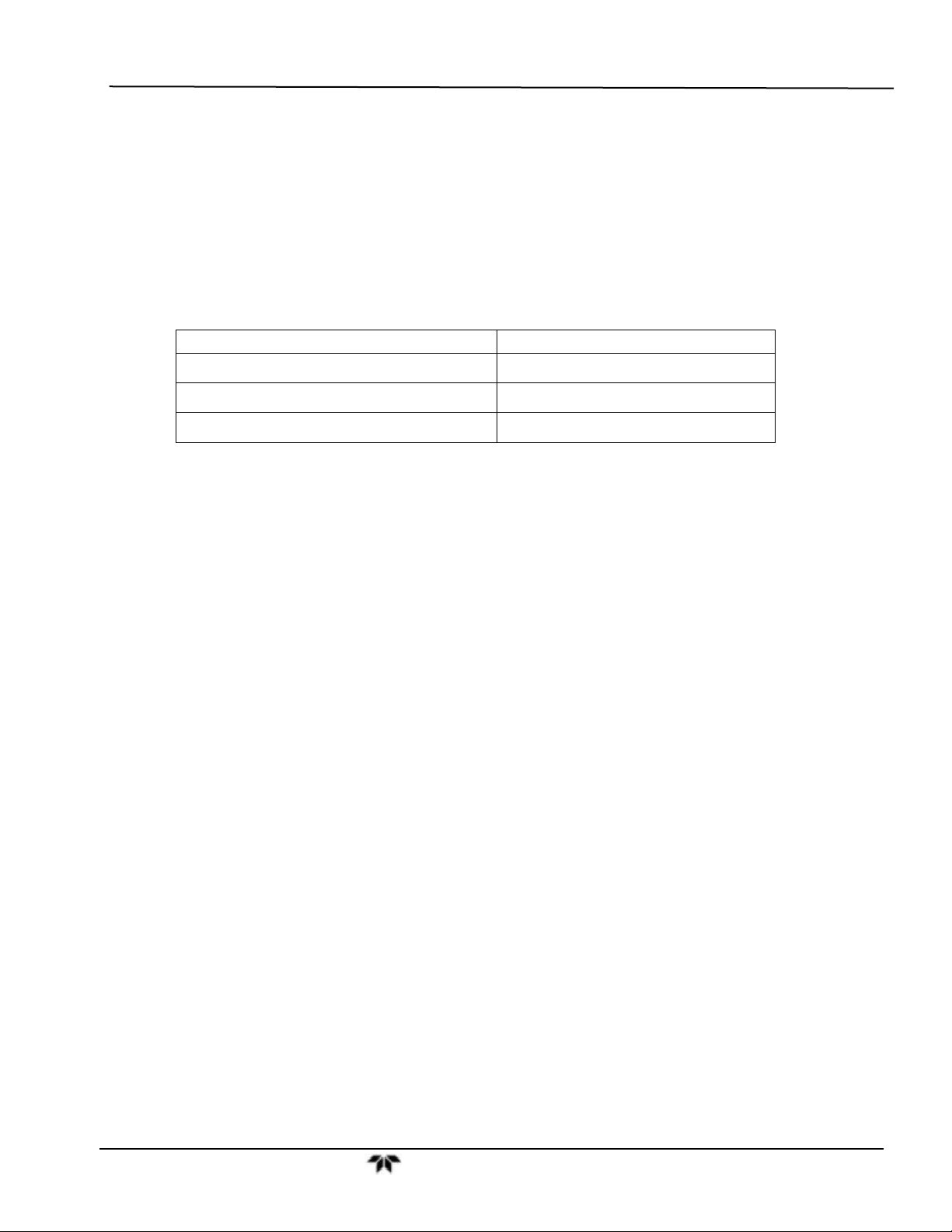
VENTILATION CLEARANCE: Whether the analyzer is set up on a bench or installed into an instrument
rack, be sure to leave sufficient ventilation clearance.
AREA MINIMUM REQUIRED CLEARANCE
Back of the instrument
4 in.
Sides of the instrument
Above and below the instrument
Various rack mount kits are available for this analyzer. See Section 5.1 of this manual for more
information.
1 in.
1 in.
Teledyne Analytical Instruments 10
Page 29
Getting Started Model GFC7000TA Carbon Dioxide Analyzer
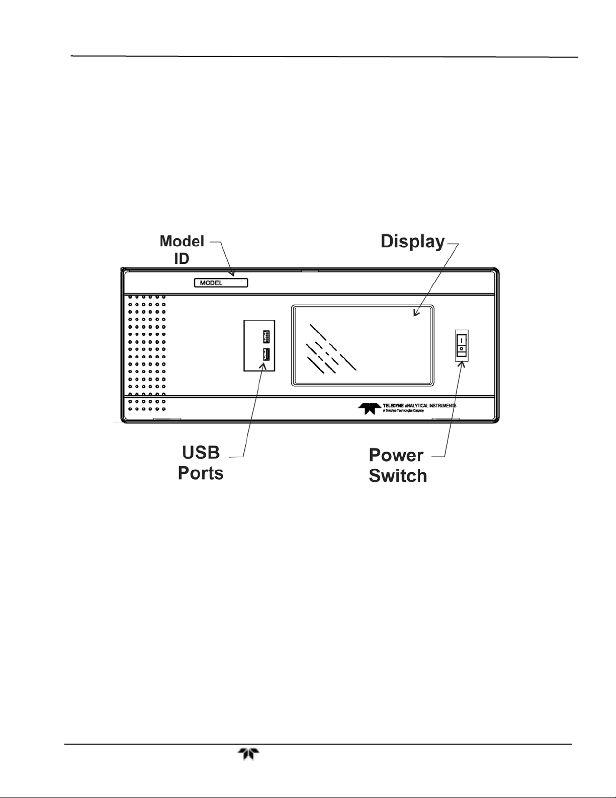
3.2. Front Panel
Figure 3-1 shows the analyzer’s front panel layout, followed by a close-up of the display screen in Figure
3-2, which is described in Table 3-1. The two USB ports on the front panel are provided for the
connection of peripheral devices:
plug-in mouse (not included) to be used as an alternative to the touchscreen interface
thumb drive (not included) to download updates to instruction software (contact TAI Customer
Service for information).
Figure 3-1: Front Panel Layout
Teledyne Analytical Instruments 11
Page 30
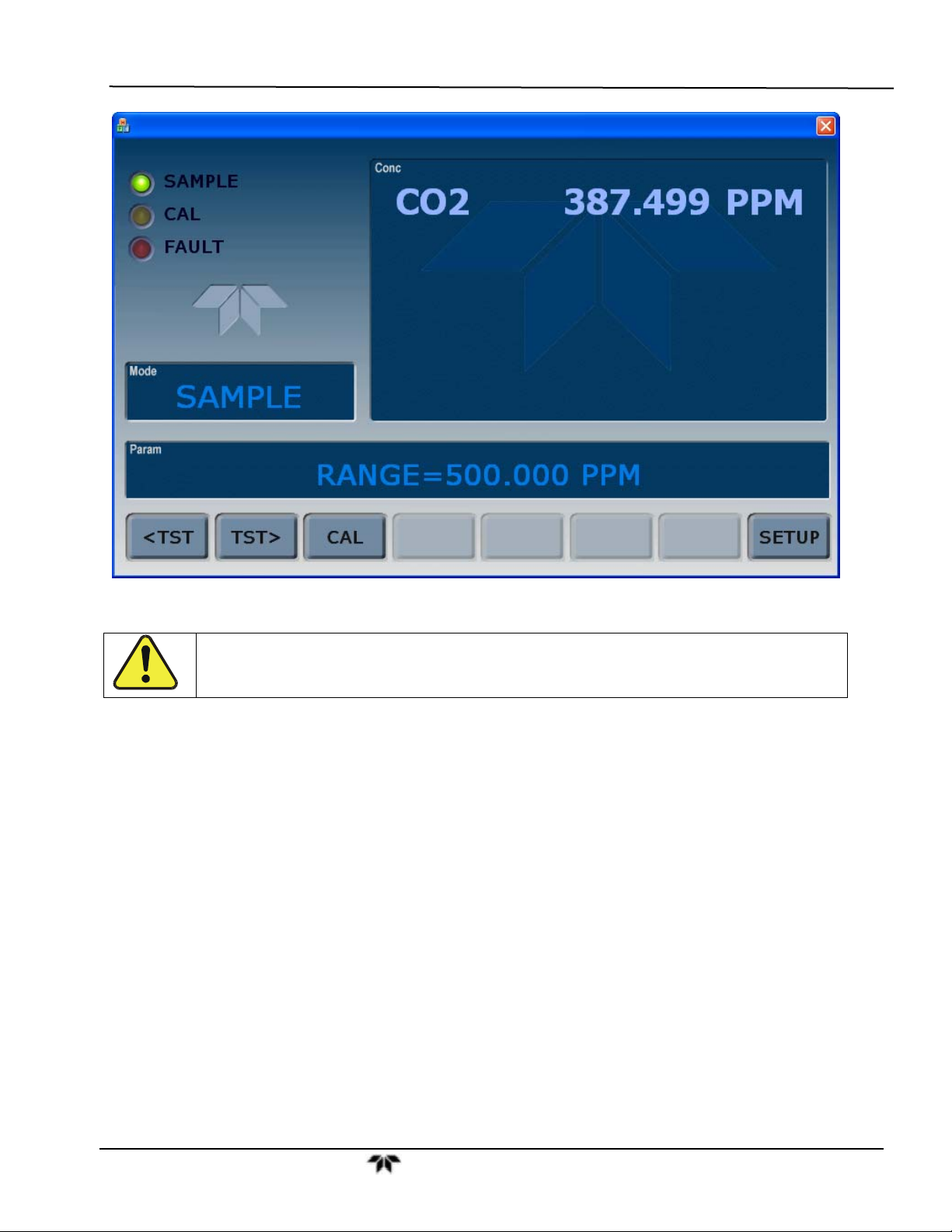
Getting Started Model GFC7000TA Carbon Dioxide Analyzer
Figure 3-2: Display Screen and Touch Control
CAUTION – Avoid Damaging Touchscreen
Do not use hard-surfaced instruments such as pens to operate the touchscr een.
The front panel liquid crystal display includes touch control. Upon analyzer start-up, the display shows a
splash screen and other initialization indicators before the main display appears, similar to Figure 3-2
above (may or may not display a Fault alarm). The LEDs on the display screen indicate the Sample,
Calibration and Fault states; also on the screen is the gas concentration field (Conc), which displays realtime readouts for the primary gas and for the secondary gas if installed. The display screen also shows
which mode the analyzer is currently in (Mode field), as well as messages and data (Param field). Along
the bottom of the screen is a row of touch control buttons; only those that are currently applicable will
have a label. Table 3-1 provides detailed information for each component of the screen.
Teledyne Analytical Instruments 12
Page 31

Getting Started Model GFC7000TA Carbon Dioxide Analyzer
Table 3-1: Display and Touchscreen Control Description
Field Description/Function
Status LEDs indicating the states of Sample, Calibration and Fault, as follows:
Name Color State Definition
Off
On
SAMPLE Green
CAL Yellow
FAULT Red
Conc
Mode Displays the name of the analyzer’s current operating mode
Param
Control Buttons Displays dynamic, context sensitive labels on each button, which is blank when inactive until applicable.
Displays the actual concentration of the sample gas currently being measured by the analyzer in the
currently selected units of measure
Displays a variety of informational messages such as warning messages, operational data, test function
values and response messages during interactive tasks.
Blinking
Off
On
Blinking
Off
Blinking
Unit is not operating in sample mode, DAS is disabled.
Sample Mode active; Front Panel Display being updated; DAS data
being stored.
Unit is operating in sample mode, front panel display being updated,
DAS hold-off mode is ON, DAS disabled
Auto Cal disabled
Auto Cal enabled
Unit is in calibration mode
No warnings exist
Warnings exist
Figure 3-3 shows how the front panel display is mapped to the menu charts illustrated in this manual. The
Mode, Param (parameters), and Conc (gas concentration) fields in the display screen are represented
across the top row of each menu chart. The eight touchscreen control buttons along the bottom of the
display screen are represented in the bottom row of each menu chart.
Teledyne Analytical Instruments 13
Page 32

Getting Started Model GFC7000TA Carbon Dioxide Analyzer
Figure 3-3: Display/Touch Control Screen Mapped to Menu Charts
Teledyne Analytical Instruments 14
Page 33

Getting Started Model GFC7000TA Carbon Dioxide Analyzer
3.3. Rear Panel
Figure 3-4: Rear Panel Layout
Table 3-2 provides a description of each component on the rear panel
Teledyne Analytical Instruments 15
Page 34

Getting Started Model GFC7000TA Carbon Dioxide Analyzer
Table 3-2: Rear Panel Description
Component Function
cooling fan
AC power
connector
Model/specs label
PURGE IN
SAMPLE
EXHAUST
VENT SPAN
PRESSURE SPAN
RX TX
COM 2
RS-232
DCE DTE
STATUS
ANALOG OUT
CONTROL IN
ALARM
ETHERNET
ANALOG IN
USB
Information Label
Pulls ambient air into chassis through side vents and exhausts through rear
Connector for three-prong cord to apply AC power to the analyzer
CAUTION! The cord’s power specifications (specs) MUST comply with the power
specs on the analyzer’s rear panel Model number label
Identifies the analyzer model number and provides power specs
Connect a gas line from the source of sample gas here
Calibration gases are also inlet here on units without zero/span valve options installed
Connect an exhaust gas line of not more than 10 meters long here that leads outside
the shelter or immediate area surrounding the instrument
Span gas vent outlet for units with zero/span valve options installed
Connect an exhaust gas line of not more than 10 meters long here
On units with zero/span valve options installed, connect a gas line to the source of
calibrated span gas here
Internal Zero Air: On units with zero/span valve options installed but no internal zero
IZS
air scrubber attach a gas line to the source of zero air here
LEDs indicate receive (RX) and transmit (TX) activity on the when blinking
Serial communications port for RS-232 or RS-485
Serial communications port for RS-232 only
Switch to select either data terminal equipment or data communication equipment
during RS-232 communication
For outputs to devices such as Programmable Logic Controllers (PLCs)
For voltage or current loop outputs to a strip chart recorder and/or a data logger
For remotely activating the zero and span calibration modes
Option for concentration alarms and system warnings
Connector for network or Internet remote communication, using Ethernet cable
Option for external voltage signals from other instrumentation and for logging these
signals
Com port optional connector for direct connection to laptop computer, using USB cable
Includes voltage and frequency specifications
Teledyne Analytical Instruments 16
Page 35

Getting Started Model GFC7000TA Carbon Dioxide Analyzer
3.4. Internal Layout
Figure 3-3 shows a top-down view of the analyzer. The shown configuration includes the Ethernet board,
IZS option, zero-air scrubber and an additional sample dryer. See Section 5 for optional equipment.
Figure 3-5: Internal Chassis Layout
Teledyne Analytical Instruments 17
Page 36

Getting Started Model GFC7000TA Carbon Dioxide Analyzer
Opto-Pickup
PCA
GFC Temperature
Sensor
Sync/Demod PCA
Housing
GFC Heater
Sample Gas Flow
Sensor
Purge Gas
Inlet
GFC Wheel
Heat Sync
GFC Wheel Motor
IR Source
Sample Gas Outlet
fitting
Sample Chamber
Pressure Sensor(s)
Shock Absorbing
Mounting Bracket
Purge Gas
Pressure Regulator
Bench
Temperature
Thermistor
Figure 3-6: Optical Bench Layout
Teledyne Analytical Instruments 18
Page 37

Getting Started Model GFC7000TA Carbon Dioxide Analyzer
Purge Gas
Flow Control
Figure 3-7: GFC 7000TA Internal Gas Flow
3.5. Electrical Connections
WARNING
Never disconnect PCAs, wiring harnesses or electronic subassemblies while the
To maintain compliance with EMC standards, it is required that the cable length be no greater than 3
meters for all I/O connections, which include Analog In, Analog Out, Status Out, Control In, Ethernet/LAN,
USB, RS-232, and RS-485.
Refer to Figure 3-4 for the locations of the rear panel connections.
instrument is under power.
NOTE
Teledyne Analytical Instruments 19
Page 38

Getting Started Model GFC7000TA Carbon Dioxide Analyzer
3.5.1. Power Connection
WARNING
Power connection must have functioning ground connection.
Do not defeat the ground wire on power plug.
Check the voltage and frequency specifications on the rear panel Model Label for
compatibility with the local power before plugging the analyzer into line power.
Do not plug in the power cord if the voltage or frequency is incorrect.
The GFC 7000TA analyzer can be configured for both 100-130 V and 210-240 V at either 50 or 60 Hz.
To avoid damage to your analyzer, make sure that the AC power voltage matches the voltage indicated
on the rear panel serial number label and that the frequency is between 47 and 63 Hz.
Turn off analyzer power before disconnecting or
connecting electrical subassemblies.
Do not operate with cover off.
CAUTION
Attach the power cord to the analyzer and plug it into a power outlet capable of carrying at least 10 A
current at your AC voltage and that it is equipped with a functioning earth ground.
3.5.2. Connecting Analog Inputs (Option 64)
The Analog In connector is used for connecting external voltage signals from other instrumentation (such
as meteorological instruments) and for logging these signals in the analyzer’s internal DAS. The input
voltage range for each analog input is 0-10 VDC.
Figure 3-8: Analog In Connector
Teledyne Analytical Instruments 20
Page 39

Getting Started Model GFC7000TA Carbon Dioxide Analyzer
A
Pin assignments for the Analog In connector are presented in Table 3-3.
Table 3-3: Analog Input Pin Assignments
PIN DESCRIPTION
1 Analog input # 1 AIN 1
2 Analog input # 2 AIN 2
3 Analog input # 3 AIN 3
4 Analog input # 4 AIN 4
5 Analog input # 5 AIN 5
6 Analog input # 6 AIN 6
7 Analog input # 7 AIN 7
8 Analog input # 8 AIN 8
GND Analog input Ground N/A
1
See Section 6.7 for details on setting up the DAS.
DAS
PARAMETER
1
3.5.3. Connecting Analog Outputs
The GFC 7000TA is equipped with several analog output channels accessible through a connector on the
back panel of the instrument. The standard configuration for these outputs is mVDC. An optional current
loop output is available for each.
When the instrument is in its default configuration, channels A1 and A2 output a signal that is proportional
to the CO
to a chart recorder or for interfacing with a data logger.
Output A3 is only used if the optional O
Channel A4 is special. It can be set by the user (see Section 6.13.9) to output any one of the parameters
accessible through the <TST TST> keys of the units sample display.
To access these signals attach a strip chart recorder and/or data-logger to the appropriate analog output
connections on the rear panel of the analyzer.
concentration of the sample gas. Either can be used for connecting the analog output signal
2
sensor is installed.
2
A1 A2 A3
ANALOG
4
1 2 3 4 5 6 7 8
Pin-outs for the analog output connector at the rear panel of the instrument are:
Teledyne Analytical Instruments 21
Page 40

Getting Started Model GFC7000TA Carbon Dioxide Analyzer
Table 3-4: GFC 7000TA Analog Output Pin Outs
PIN ANALOG OUTPUT VDC SIGNAL MADC SIGNAL
1
2 Ground I Out 3
4 Ground I Out 5
6 Ground I Out -
7
8 Ground Not used
(Only used if O2 sensor
A1
A2
A3
is installed)
A4
The default analog output voltage setting of the GFC 7000TA CO2 Analyzer is 0 – 5 VDC with
a range of 0 – 500 ppm.
TO change these settings, see Sections 6.13.4 and 6.8 respectively.
V Out I Out +
V Out I Out +
V Out I Out +
V Out Not used
Teledyne Analytical Instruments 22
Page 41

Getting Started Model GFC7000TA Carbon Dioxide Analyzer
3.5.4. Connecting the Status Outputs
If you wish utilize the analyzer’s status outputs to interface with a device that accepts logic-level digital
inputs, such as programmable logic controllers (PLC’s) they are accessed via a 12-pin connector on the
analyzer’s rear panel labeled STATUS.
1 2 3 4 5 6 7 8 D
STATUS
+
NOTE
Most PLC’s have internal provisions for limiting the current the input will draw.
When connecting to a unit that does not have this feature, external resistors must
be used to limit the current through the individual transistor outputs to ≤50mA
(120 Ω for 5V supply).
The pin assignments for the status outputs can be found in the table below:
Table 3-5: Status Output Pin-outs
OUTPUT #
1
2
3
4
5
6
7
8
D EMITTER BUS The emitters of the transistors on pins 1-8 are bused together.
+ DC POWER + 5 VDC
STATUS
DEFINITION
SYSTEM OK
CONC VALID
HIGH RANGE
ZERO CAL
SPAN CAL
DIAG MODE
ALARM1
ALARM2
CONDITION
On if no faults are present.
On if CO2 concentration measurement is valid.
If the CO
On if unit is in high range of DUAL or AUTO range modes.
On whenever the instruments ZERO point is being calibrated.
On whenever the instruments SPAN point is being calibrated.
On whenever the instrument is in DIAGNOSTIC mode.
On whenever the measured CO
ALM1
On whenever the measured CO2 concentration is above the set point for
ALM2
concentration measurement is invalid, this bit is OFF.
2
concentration is above the set point for
2
Digital Ground The ground level from the analyzer’s internal DC power supplies.
Teledyne Analytical Instruments 23
Page 42

Getting Started Model GFC7000TA Carbon Dioxide Analyzer
3.5.5. Connecting the Control Inputs
If you wish to use the analyzer to remotely activate the zero and span calibration modes, several digital
control inputs are provided through a 10-pin connector labeled CONTROL IN on the analyzer’s rear
panel.
There are two methods for energizing the control inputs. The internal +5V available from the pin labeled
“+” is the most convenient method. However, if full isolation is required, an external 5 VDC power supply
should be used.
CONTROL IN
A B C D E F U +
S
Z
P
E
A
R
N
O
Local Power Connections
A B C D E F U +
S
Z
P
E
A
R
N
O
-
External Power Connections
CONTROL IN
5 VDC Power
Supply
+
The pin assignments for the digital control inputs can be found in the table below:
Table 3-6: Control Input Pin-outs
INPUT #
A
B
C
D
E
F
U
+
STATUS
DEFINITION
REMOTE ZERO
CAL
REMOTE
SPAN CAL
The Analyzer is placed in Zero Calibration mode. The mode field of
the display will read ZERO CAL R.
The Analyzer is placed in Span Calibration mode. The mode field of
the display will read SPAN CAL R.
SPARE
SPARE
SPARE
SPARE
Digital Ground May be connected to the ground of the data logger/recorder.
Pull-up supply for
inputs
Internal +5V
Supply
Input pin for +5 VDC required to activate pins A – F. This can be from
an external source or from the “+” pin of the instruments STATUS
connector.
Internal source of +5V which can be used to actuate control inputs
when connected to the U pin.
ON CONDITION
Teledyne Analytical Instruments 24
Page 43

Getting Started Model GFC7000TA Carbon Dioxide Analyzer
3.5.6. Connecting the Communications Interfaces
For RS-232 or RS-485 communications through the analyzer’s serial interface com ports, refer to Section
6.11 of this manual for instructions on their configuration and usage.
3.5.6.1. Connecting to a LAN or the Internet
For network or Internet communication with the analyzer, connect an Ethernet cable from the analyzer’s
rear panel Ethernet interface connector to an Ethernet access port.
NOTE:
The GFC 7000TA firmware supports dynamic IP addressing or DHCP.
If your network also supports DHCP, the analyzer will automatically configure its
LAN connection appropriately,
If your network does not support DHCP, see Section 6.11.6.3 for instructions on
manually configuring the LAN connection.
3.5.6.2. Connecting to a Personal Computer (PC)
If the analyzer is configured with the USB com option, connect a USB cable between the USB ports of the
analyzer’s rear panel and a desktop or laptop PC for direct communication between the two. Their baud
rates must match (see Section 6.11.8).
3.5.6.3. Connecting to a Multidrop Network
If your unit has a Teledyne Instruments RS-232 multidrop card (Option 62), see Section 6.11.7 for
instructions on setting it up.
3.6. Pneumatic Connections
CAUTION!
Do not operate this instrument until you’ve removed dust plugs from SAMPLE and EXHAUST
ports on the rear panel!
Teledyne Analytical Instruments 25
Page 44

Getting Started Model GFC7000TA Carbon Dioxide Analyzer
3.6.1. Basic Pneumatic Connections
NOTE
In order to prevent dust from getting into the gas flow channels of your analyzer,
it was shipped with small plugs inserted into each of the pneumatic fittings on the
back panel. Remove these plugs before operating the analyzer. It is recommended
that they be stored for future use (moving, storing or shipping the analyzer).
Figure 3-4 illustrates the basic configuration for gas supply and exhaust lines to the Model GFC 7000TA
Analyzer. Figure 3-5 illustrates the internal gas flow of the instrument in its basic configuration.
Please refer to Figure 3-2 for pneumatic connections at the rear panel and Table 3-2 for description.
NOTE
Sample and calibration gases should only come into contact with PTFE (Teflon),
FEP, glass, stainless steel or brass.
Table 3-7: Rear Panel Pneumatic Connections
REAR PANEL LABEL FUNCTION
Connect a gas line from the source of sample gas here.
SAMPLE
EXHAUST
PRESSURE SPAN
VENT SPAN
IZS
PURGE IN
Calibration gasses are also inlet here on units without zero/span valve or IZS
options installed.
Connect an exhaust gas line of not more than 10 meters long here.
On units with zero/span valve options installed, connect a gas line to the source
of calibrated span gas here.
Span gas vent outlet for units with zero/span valve options installed.
Connect an exhaust gas line of not more than 10 meters long here.
Internal zero air scrubber.
On units with zero/span valve options installed but no internal zero air
scrubber, attach a gas line to the source of zero air here.
This inlet supplies purge air to the GFC wheel housing (see Section 10.2.3)
Connect a source of dried air that has been scrubbed of CO
.
2
Teledyne Analytical Instruments 26
Page 45

Getting Started Model GFC7000TA Carbon Dioxide Analyzer
Figure 3-9: Pneumatic Connections–Basic Configuration–Using Bottled Span Gas
Figure 3-10: Pneumatic Connections–Basic Configuration–Using Gas Dilution Calibrator
Teledyne Analytical Instruments 27
Page 46

Getting Started Model GFC7000TA Carbon Dioxide Analyzer
7. Attach a sample inlet line to the sample inlet port. The SAMPLE input line should not be more
than 2 meters long.
NOTE
Ideally, the pressure of the sample gas should be at ambient pressure (0 psig).
Maximum pressure of sample gas should not exceed 1.5 in-Hg over ambient.
In applications where the sample gas is received from a pressurized manifold, a vent
must be placed as shown to equalize the sample gas with ambient atmospheric
pressure before it enters the analyzer.
This vent line must be:
At least 0.2m long
No more than 2m long and vented outside the shelter or immediate area
surrounding the instrument.
8. Attach sources of zero air and span gas (see Figures 3-3 through 3-8 inclusive).
Span Gas is a gas specifically mixed to match the chemical composition of the type of gas
being measured at near full scale of the desired measurement range.
In the case of CO
Analyzer it is recommended that you use a gas calibrated to have a CO
measurements made with the Teledyne Instruments Model GFC 7000TA
2
content equaling
2
80% of the range of compositions being measured.
EXAMPLE: If the application is to measure between 0 ppm and 500 ppm, an appropriate Span
Gas would be 400 ppm. If the application is to measure between 0 ppm and 100 ppm, an
appropriate Span Gas would be 80 ppm.
Span Gas can be purchased in pressurized canisters or created using Dynamic Dilution
Calibrator such as the Teledyne Instruments Model T700 and a source of dried air scrubbed
of CO
such as a bottle of N2.
2
Zero Air is similar in chemical composition to the Earth’s atmosphere but scrubbed of all
components that might affect the analyzer’s readings.
In the case of CO
measurements this means less than 0.1 ppm of CO2 and Water Vapor
2
(when dew point <-15˚C). Zero Air can be purchased in pressurized canisters.
9. Attach an exhaust line to the exhaust outlet port.
The exhaust from the pump and vent lines should be vented to atmospheric pressure using
maximum of 10 meters of ¼” PTEF tubing.
CAUTION
Venting should be outside the shelter or immediate area surrounding the instrument.
Teledyne Analytical Instruments 28
Page 47

Getting Started Model GFC7000TA Carbon Dioxide Analyzer
10. Attach a source of dried air scrubbed of CO2 to the purge inlet port.
NOTE
The minimum gas pressure of the source of purge air should be 7.5 psig.
If the source of the purge air is shared by a Teledyne Instruments T700 (as shown
in figure 3-7) the minimum gas pressure should be 25 psig and should not exceed
35 psig.
11. Once the appropriate pneumatic connections have been made, check all pneumatic fittings for
leaks using a procedure similar to that defined in Section 9.3.3.
Teledyne Analytical Instruments 29
Page 48

Getting Started Model GFC7000TA Carbon Dioxide Analyzer
3.6.2. Connections with Internal Valve Options Installed
Figure 3-11 and Figure 3-12 show the pneumatic connections for the ambient zero and ambient span
valve option (Option 50A).
Figure 3-11: Pneumatic Connections with Ambient Zero/Ambient Span Valves (OPT 50A)
Figure 3-12: Pneumatic Connections with Ambient Zero/Ambient Span Valves (Opt 50A) and
External Zero Air Scrubber
Teledyne Analytical Instruments 30
Page 49

Getting Started Model GFC7000TA Carbon Dioxide Analyzer
Figure 3-13 and Figure 3-14 show the pneumatic connections for the ambient zero and ambient span
valve option (Option 50B).
VENT
Figure 3-13: Pneumatic Connections with Ambient Zero/Pressurized Span Valves (OPT 50B)
Figure 3-14: Pneumatic Connections with Ambient Zero/Pressurized Span Valves (Opt 50B) and
External Zero Air Scrubber
Teledyne Analytical Instruments 31
Page 50

Getting Started Model GFC7000TA Carbon Dioxide Analyzer
3.6.3. Pneumatic Connections in Multipoint Calibration Applications
Some applications may require multipoint calibration checks where span gas of several different
concentrations is needed. We recommend using high-concentration, certified, calibration gas supplied to
the analyzer through a Gas Dilution Calibrator such as a Teledyne Instruments Model T700. This type of
calibrator precisely mixes Span Gas and Zero Air to produce any concentration level between 0 ppm and
the concentration of the calibrated gas.
Figure 3-12 depicts the pneumatic set up in this sort of application of a Model GFC 7000TA CO
with ambient zero/ambient span valve option 50A installed (a common configuration for this type of
application).
Analyzer
2
Figure 3-15: Example of Pneumatic Set up for Multipoint Calibration
3.6.4. Setting the Internal Purge Air Pressure
In order to maintain proper purge air flow though the GFC wheel housing, a manually adjustable pressure
regulator is provided (see Figure 3-5). This regulator includes two output ports. One is used to supply
purge air to the GFC wheel. The other may be used to attach a pressure gauge.
To adjust the internal purge air pressure of the GFC 7000TA:
1. Turn off the instrument.
2. Remove the source of zero air attached to the purge line inlet port at the back of the analyzer.
3. Remove the analyzer’s top cover.
4. Remove the cap from the second, unused, output port on the pressure regulator.
5. Attach a pressure gauge capable of measuring in the 5-10 psig range with 0.5 psig resolution to
the port.
Teledyne Analytical Instruments 32
Page 51

Getting Started Model GFC7000TA Carbon Dioxide Analyzer
6. Turn the instrument on.
7. Make sure the zero air supply to the analyzer’s purge line inlet is supplying gas at a stable
pressure above 7.5 psig.
8. Adjust the GFC 7000TA’s pressure regulator until the attached gauge reads 7.5 psig.
9. Turn off the instrument.
10. Remove the source of zero air attached to the purge line inlet port at the back of the analyzer.
11. Remove the pressure gauge and reattach the end cap removed in step 4 above.
12. Replace the analyzer’s top cover.
3.7. Initial Operation
If you are unfamiliar with the GFC 7000TA theory of operation, we recommend that you read
Section 10. For information on navigating the analyzer’s software menus, see the menu trees described
in Appendix A.
NOTE
The analyzer’s cover must be installed to ensure that the temperatures of the GFC
wheel and absorption cell assemblies are properly controlled.
3.7.1. Startup
After electrical and pneumatic connections are made, and initial functional check is required. Turn on the
instrument. The pump, exhaust fan and PMT cooler fan should start immediately. The display will briefly
show a logo splash screen at the start of initialization.
The analyzer should automatically switch to Sample Mode after completing the boot-up sequence and
start monitoring CO
gas measurements can be taken. During the warm-up period, the front panel display may show
messages in the Parameters field.
gas. However, there is an approximately one hour warm-up period before reliable
2
Teledyne Analytical Instruments 33
Page 52

Getting Started Model GFC7000TA Carbon Dioxide Analyzer
3.7.2. Warm Up
During the warm-up period various portions of the instrument’s front panel may behave as indicated in
Table 3-8.
Table 3-8: Front Panel Display During System Warm-Up
NAME COLOR BEHAVIOR SIGNIFICANCE
Displays current,
Conc field N/A
compensated CO
Concentration
Displays current
Mode field N/A
mode, e.g.,
SAMPLE”
Param field N/A
Displays menu items
and messages.
STATUS LEDs
Sample Green On
Cal Yellow Off The instrument’s calibration is not enabled.
Fault Red Blinking
This is normal operation, but deemed inaccurate during the
2
warm-up period.
Instrument is in Sample mode but is still in the process of
warming up. (DAS holdoff period is active)
Refer to Table 3-9 for a list and descriptions of warning
messages.
Unit is operating in sample mode; front panel display is
being updated.
Flashes On/Off when adaptive filter is active
The analyzer is warming up and hence out of specification
for a fault-free reading. Various warning messages appear
in the Param field.
3.7.3. Warning Messages
Because internal temperatures and other conditions may be outside be specified limits during the
analyzer’s warm-up period, the software will suppress most warning conditions for 30 minutes after power
up. If warning messages persist after the 30 minutes warm up period is over, investigate their cause
using the troubleshooting guidelines in Section 11 of this manual.
To view and clear warning messages, press:
TEST
deactivates warning
messages
If the warning message persists
after several attempts to clear it,
the message may indicate a
real problem and not an artifact
NOTE:
of the warm-up period
SAMPLE HVPS WARNING CO2 = 0.00
TEST CAL MSG CLR SETUP
SAMPLE
< TST TST > CAL
SAMPLE
TEST CAL MSG
Make sure warning messages are
not due to real problems.
RANGE=500.000 PPM
HVPS WARNING
CO2 = 0.00
CLR SETUP
MSG
CO2 = 0.00
CLR
SETUP
MSG
activates warning
messages.
<TST TST
Press
If more than one warning is active, the
next message will take its place
Once the last warning has been
cleared, the analyzer returns to
> keys replaced with
TEST
key
CLR
to clear the current
message.
SAMPLE
mode
Table 3-6 lists brief descriptions of the warning messages that may occur during start up.
Teledyne Analytical Instruments 34
Page 53

Getting Started Model GFC7000TA Carbon Dioxide Analyzer
Table 3-9: Possible Warning Messages at Start-Up
MESSAGE MEANING
ANALOG CAL WARNING
BENCH TEMP WARNING
BOX TEMP WARNING
CANNOT DYN SPAN
CANNOT DYN ZERO
CONC ALRM1 WARNING
CONC ALRM2 WARNING
CONFIG INITIALIZED
DATA INITIALIZED
O2 CELL TEMP WARN
PHOTO TEMP WARNING
The instrument’s A/D circuitry or one of its analog outputs is not calibrated.
The optical bench Temperature is outside the specified limits.
Remote span calibration failed while the dynamic span feature was set to turned on.
Remote zero calibration failed while the dynamic zero feature was set to turned on.
Configuration was reset to factory defaults or was erased.
Concentration alarm 1 is enabled and the measured CO2 level is ≥ the set point.
Concentration alarm 2 is enabled and the measured CO2 level is ≥ the set point.
Configuration storage was reset to factory configuration or erased.
DAS data storage was erased.
O2 sensor cell temperature outside of warning limits.
The temperature of the IR photometer is outside the specified limits.
REAR BOARD NOT DET
RELAY BOARD WARN
SAMPLE FLOW WARN
SAMPLE PRESS WARN
SAMPLE TEMP WARN
SOURCE WARNING
SYSTEM RESET
WHEEL TEMP WARNING
The CPU is unable to communicate with the motherboard.
The firmware is unable to communicate with the relay board.
The flow rate of the sample gas is outside the specified limits.
Sample gas pressure outside of operational parameters.
The temperature of the sample gas is outside the specified limits.
The IR source may be faulty.
The computer was rebooted.
The Gas Filter Correlation wheel temperature is outside the specified limits.
Teledyne Analytical Instruments 35
Page 54

Getting Started Model GFC7000TA Carbon Dioxide Analyzer
1
g
3.7.4. Functional Check
1. After the analyzer’s components has warmed up for at least 30 minutes, verify that the software
properly supports any hardware options that were installed.
2. Check to make sure that the analyzer is functioning within allowable operating parameters.
Appendix C includes a list of test functions viewable from the analyzer’s front panel as well as
their expected values. These functions are also useful tools for diagnosing performance
problems with your analyzer (Section11.1.2). The enclosed Final Test and Validation Data sheet
(part number 04307) lists these values before the instrument left the factory.
To view the current values of these parameters press the following button sequence on the analyzer’s
front panel. Remember until the unit has completed its warm up these parameters may not have
stabilized.
SAMPLE RANGE = 500.000 PPM CO2 = XXX.X
< TST TST > CAL SETUP
Toggle <TST TST> buttons
to scroll throu
Only appears instrument is set
for DU AL or AUTO reporting
range modes.
2
Only appears if O2 Sensor
Option is installed.
h list of
RANGE
RANGE1
RANGE2
O2 RANGE
STABIL
MR RATIO
SAMP FL
SAMP TEMP
BENCH TEMP
WHEEL TEMP
BOX TEM P
PHT DRIVE
SLOPE
OFFSET
MEAS
REF
PRES
TEST
TIME
1
1
2
Refer to
Table 6-2 for
definitions of
these test
functions.
If your network is running a dynamic host configuration protocol (DHCP) software package, the
Ethernet feature will automatically configure its interface with your LAN. (See Section 6.11.6.2).
This configuration is useful for quickly getting an instrument up and running on a network.
However, for permanent Ethernet connections, a static IP address should be used. (See Section
6.11.6.3).
Teledyne Analytical Instruments 36
Page 55

Getting Started Model GFC7000TA Carbon Dioxide Analyzer
3.8. Initial Calibration Procedure
The next task is to calibrate the analyzer.
To perform the following calibration you must have sources for zero air and span gas available for input
into the sample port on the back of the analyzer. See Section 3.1.3 for instructions for connecting these
gas sources.
While it is possible to perform this procedure with any range setting we recommend that you perform this
initial checkout using the 500 ppm range.
NOTE
The following procedure assumes that the instrument does not have any of the available
Zero/Span Valve Options installed.
See Section 7.4 for instructions for calibrating instruments possessing Z/S valve options.
1. Set the Analog Output Range:
Press this button to set
the analyzer for SNGL
DUAL or AUTO ranges
To change the value of the
reporting range span, enter the
number by pressing the key under
each digit until the expected value
appears.
SAMPLE RANGE = 500.000 PPM CO2 =X.XXX
< TST TST > CAL SETUP
SETUP X.X
CFG DAS RNGE PASS CLK MORE EXIT
SETUP X.X RANGE CONTROL MENU
MODE
SET UNIT EXIT
SETUP X.X RANGE: 500.000 CONC
0 0 5 0 0 .0 ENTR EXIT
SETUP X.X RANGE: 500.000 Conc
0 0 0 5 0 .0 ENTR EXIT
Press this button to select the
concentration units of measure:
PPB, PPM, UGM, MGM
EXIT ignores the new setting and
returns to the RANGE CONTROL
ENTR accepts the new setting and
RANGE CONTROL MENU.
MENU.
returns to the
Teledyne Analytical Instruments 37
Page 56

Getting Started Model GFC7000TA Carbon Dioxide Analyzer
2. Set the expected CO2 span gas concentration
The CO2 span
concentratio n valu es
automatically default to
40 0. 0 C o nc.
To change this value to
the a ctual concen tr ation of
th e span gas, en te r the
number by pressing the
button und er e ach digit
until the expect ed value
appears.
SAMPLE* RANGE = 500.000 PPM CO2 =X.XXX
< TST TST > CAL SETUP
M-P CAL RANGE = 500.000 PPM CO2 =X.XXX
< TST TST > ZERO CONC EXIT
M-P CAL CO2 SPAN CONC: 400.000 Conc
0 0 0 4 5 .0 ENTR EXIT
This sequence causes the
analyzer to pr ompt for the
expe cted CO
co ncent ratio n.
EXIT ignores the new setting
and returns to t he previ ous
ENTR accepts the new setting
and returns to the
previous display..
span
2
display.
NOTE
For this Initial Calibration it is important to independently verify the precise CO2
Concentration Value of the SPAN gas.
If the source of the Span Gas is from a Calibrated Bottle, use the exact
concentration value printed on the bottle.
Teledyne Analytical Instruments 38
Page 57

Getting Started Model GFC7000TA Carbon Dioxide Analyzer
A
A
3. Perform the Zero/Span Calibration Procedure
SAMPLE* RANGE = 500.000 PPM CO2 =XXX.X
< TST TST > CAL SETUP
SAMPLE STABIL=XXX.X PPM CO2 =XXX.X
< TST TST > CAL SETUP
Allow zero gas to enter the sample port at the
M-P CAL STABIL=XXX.X PPM CO2 =XXX.X
< TST TST > CAL SETUP
M-P CAL STABIL=XXX.X PPM CO2 =XXX.X
< TST TST > ZERO CONC EXIT
M-P CAL STABIL=XXX.X PPM CO2 =XXX.X
< TST TST > ENTR CONC EXIT
CTION:
rear of the instru ment.
Set the Display to show the
STABIL test function.
Th is function calcul ates the
stability of the CO
m easurem ent
Wait until STABIL
falls below 1.0 ppm.
This may take several
minutes.
Press ENTR to changes the
OFFSE T & SLOPE values fo r th e
CO
m easu remen ts.
2
Press EXIT to leave the calibration
unchanged and return to the
previ ous me nu.
x
The SPAN button now
appears during the
transition from zero to
span..
If either the ZERO or
SPAN buttons fail to
appear see Section 11
for tr ouble shoo ting tips.
Allow span gas to enter the sample port at the
M-P CAL STAB IL=XXX.X PPM CO2 =XXX.X
< TST TST > SPAN CONC EXIT
M-P CAL RANGE = 500.000 PPM CO2 =XXX.X
< TST TST > ENTR SPAN CONC EXIT
M-P CAL RANGE = 500.000 PPM CO2 =XXX.X
< TST TST > ENTR CONC EXIT
CTION:
rear of the instrument.
The value of
STABIL may jump
significantly.
Wai t until it falls back
below 1.0 ppm
This may take several
minutes.
Press ENTR to change the
OFFSET & SLOPE values for the
CO
m easu remen ts.
2
Press EXIT to leave the calibration
unchanged and return to the
previ ous me nu.
EXIT returns to the main
SAMPLE dis play
Teledyne Analytical Instruments 39
Page 58

Getting Started Model GFC7000TA Carbon Dioxide Analyzer
3.8.1. Initial O2 Sensor Calibration Procedure
If your instrument has an O2 sensor option installed that should be calibrated as well.
3.8.1.1. O2 Calibration Setup
The pneumatic connections for calibrating are as follows:
2
at HIGH Span
Concentration
Calibrated N
2
Concentration
Calibrated O
at 20.8% Span
VENT
Figure 3-16: O2 Sensor Calibration Set Up
SENSOR ZERO GAS: Teledyne Instruments’ recommends using pure N2 when calibration the zero
O
2
point of your O
O
SENSOR SPAN GAS: Teledyne Instruments’ recommends using 21% O2 in N2 when calibration the
2
span point of your O
sensor option.
2
sensor option.
2
3.8.1.2. O2 Calibration Method
STEP 1 – SET O2 SPAN GAS CONCENTRATION :
Set the expected O
This should be equal to the percent concentration of the O
(default factory setting = 20.8%; the approximate O
span gas concentration.
2
span gas of the selected reporting range
2
content of ambient air).
2
Teledyne Analytical Instruments 40
Page 59

Getting Started Model GFC7000TA Carbon Dioxide Analyzer
SAMPLE RANGE = 500.000 PPM CO2 =XXX.X
< TST TST > CAL SETUP
SAMPLE GAS TO CAL:CO2
CO2 O2 ENTR EXIT
SAMPLE GAS TO CAL:O2
NOX O2 ENTREXIT
The O2 span concentration value automatically defaults to
If this is not the the concentration of the span gas being
used, toggle these buttons to set the correct concentration
of the O
20.8 %.
calibration gases.
2
M-P CAL A1:NXCNC1 =100PPM NOX=X.XXX
<TST TST> ZERO SPAN CONC EXIT
M-P CAL O2 SPAN CONC:20.8%
0 2 0 .8 0 ENTREXIT
EXIT ignores the new
setting and returns to
the previous display.
ENTR accepts the new
setting and returns to
the previous menu.
STEP 2 – ACTIVATE O
SENSOR STABILITY FUNCTION
2
To change the stability test function from NO
concentration to the O2 sensor output, press:
x
Teledyne Analytical Instruments 41
Page 60

Getting Started Model GFC7000TA Carbon Dioxide Analyzer
SAMPLE RANGE = 500.000 PPM CO2 =XXX.X
< TST TST > CAL SETUP
SETUP X.X PRIMARY SETUP MENU
CFG DAS RNGE PASS CLK MORE EXIT
SETUP X.X SECONDARY SETUP MENU
COMM VARS DIAG ALRM EXIT
SETUP X.X ENTER PASSWORD:818
8 1 8 ENTREXIT
Press EXIT 3
times to return
to SAMPLE
menu
SETUP X.X 0) DAS_HOLD_OFF=15.0 Minutes
<PREV NEXT> JUMP EDIT PRNT EXIT
Continue pressing NEXT until ...
SETUP X.X 2) STABIL_GAS=CO2
<PREV NEXT> JUMP EDIT PRNT EXIT
SETUP X.X STABIL_GAS:CO2
CO2 O2 ENTR EXIT
SETUP X.X STABIL_GAS:O2
CO2 O2 ENTR EXIT
NOTE
Use the same procedure to reset the STB test function to CO2 when the O2
calibration procedure is complete.
Teledyne Analytical Instruments 42
Page 61

Getting Started Model GFC7000TA Carbon Dioxide Analyzer
STEP 4 – O2 Zero/Span Calibration perform by pressing:
The Model GFC 7000TA Analyzer is now ready for operation.
Teledyne Analytical Instruments 43
Page 62

Getting Started Model GFC7000TA Carbon Dioxide Analyzer
NOTE
Once you have completed the above set-up procedures, please fill out the Quality
Questionnaire that was shipped with your unit and return it to Teledyne
Instruments.
This information is vital to our efforts in continuously improving our service and
our products.
THANK YOU.
Teledyne Analytical Instruments 44
Page 63

FAQ Model GFC7000TA Carbon Dioxide Analyzer
4. FREQUENTLY ASKED QUESTIONS
4.1. FAQ’s
The following is a list from the Teledyne Instruments’ Customer Service Department of the most
commonly asked questions relating to the Model CO
Q: How do I get the instrument to zero / Why is the zero key not displayed?
A: See Section 11.3.4 Inability to zero.
Q: How do I get the instrument to span / Why is the span key not displayed?
A: See Section 11.3.3 Inability to span.
Q: Why does the ENTR key sometimes disappear on the Front Panel Display?
A: During certain types of adjustments or configuration operations, the ENTR key will disappear if you
select a setting that is nonsensical (such as trying to set the 24-hour clock to 25:00:00) or out of the
allowable range for that parameter (such as selecting a DAS Holdoff period of more than 20 minutes).
Once you adjust the setting in question to an allowable value, the ENTR key will re-appear.
Analyzer.
2
Q: Is there an optional midpoint calibration?
A: There is an optional mid point linearity adjustment; however, midpoint adjustment is applicable only
to applications where CO
Service Department for more information on this topic.
Q: How do I make the display and data logger analog input agree?
A: This most commonly occurs when an independent metering device is used besides the data
logger/recorded to determine gas concentration levels while calibrating the analyzer. These
disagreements result from the analyzer, the metering device and the data logger having slightly
different ground levels.
Both the electronic scale and offset of the analog outputs can be adjusted (see Section 6.13.4.3).
Alternately, use the data logger itself as the metering device during calibrations procedures.
Q: How do I perform a leak check?
A: See Section 9.3.3.
Q: How do I measure the sample flow?
A: Sample flow is measured by attaching a calibrated rotameter, wet test meter, or other flow-
measuring device to the sample inlet port when the instrument is operating. The sample flow should
be 800 cm
3
/min 10%. See Section 9.3.4.
measurements are expected above 100 ppm. Call Teledyne Instruments’
2
Q: How long does the IR source last?
A: Typical lifetime is about 2-3 years.
Teledyne Analytical Instruments 45
Page 64

FAQ Model GFC7000TA Carbon Dioxide Analyzer
Q: Where is the sintered filter/sample flow control orifice?
A: These components are located inside the flow control assembly that is attached to the inlet side of
the sample pump, see Figure 3-3. See Section 11.6.1 for instructions on disassembly and
replacement.
Q: How do I set up a SEQUENCE to run a nightly calibration check?
A: The setup of this option is located in Section 7.6.
Q: How do I set the analog output signal range and offset?
A: Instructions for this can be found in Section 6.13.4 which describes analog I/O configuration.
Q: What is the averaging time for an GFC 7000TA?
A: The default averaging time, optimized for ambient pollution monitoring, is 150 seconds for stable
concentrations and 10 seconds for rapidly changing concentrations; See Section10.5.1 for more
information. However, it is adjustable over a range of 0.5 second to 200 seconds (please contact
customer service for more information).
4.2. Glossary
Note: Some terms in this glossary may not occur elsewhere in this manual.
Term Description/Definition
10BaseT an Ethernet standard that uses twisted (“T”) pairs of copper wires to transmit at
10 megabits per second (Mbps)
100BaseT same as 10BaseT except ten times faster (100 Mbps)
APICOM name of a remote control program offered by Teledyne to its customers
ASSY
CAS
CD Corona Discharge, a frequently luminous discharge, at the surface of a
CE Converter Efficiency, the percentage of light energy that is actually converted
CEM
Chemical formulas that may be included in this document:
CO
2
C3H8 propane
CH4 methane
H2O water vapor
HC general abbreviation for hydrocarbon
Assembly
Code-Activated Switch
conductor or between two conductors of the same transmission line,
accompanied by ionization of the surrounding atmosphere and often by a power
loss
into electricity
Continuous Emission Monitoring
carbon dioxide
Teledyne Analytical Instruments 46
Page 65

FAQ Model GFC7000TA Carbon Dioxide Analyzer
Term Description/Definition
HNO3 nitric acid
H2S hydrogen sulfide
NO nitric oxide
NO2 nitrogen dioxide
NOX nitrogen oxides, here defined as the sum of NO and NO2
NOy nitrogen oxides, often called odd nitrogen: the sum of NOX plus other
compounds such as HNO
PAN, N
O and other compounds as well)
2
NH3 ammonia
O
2
molecular oxygen
O3 ozone
SO2 sulfur dioxide
3
cm
metric abbreviation for cubic centimeter (replaces the obsolete abbreviation
CPU
DAC
DAS
DCE
DFU
Central Processing Unit
Digital-to-Analog Converter
Data Acquisition System
Data Communication Equipment
Dry Filter Unit
“cc”)
DHCP Dynamic Host Configuration Protocol. A protocol used by LAN or Internet
servers to automatically set up the interface protocols between themselves and
any other addressable device connected to the network
DIAG Diagnostics, the diagnostic settings of the analyzer.
DOM Disk On Module, a 44-pin IDE flash drive with up to 128MB storage capacity for
instrument’s firmware, configuration settings and data
DOS
DRAM
DR-DOS
DTE
Disk Operating System
Dynamic Random Access Memory
Digital Research DOS
Data Terminal Equipment
EEPROM Electrically Erasable Programmable Read-Only Memory also referred to as a
FLASH chip or drive
ESD
ETEST
Electro-Static Discharge
Electrical Test
Ethernet a standardized (IEEE 802.3) computer networking technology for local area
networks (LANs), facilitating communication and sharing resources
FEP Fluorinated Ethylene Propylene polymer, one of the polymers that Du Pont
markets as Teflon
®
Flash non-volatile, solid-state memory
FPI Fabry-Perot Interface: a special light filter typically made of a transparent plate
with two reflecting surfaces or two parallel, highly reflective mirrors
(definitions vary widely and may include nitrate (NO3),
3
Teledyne Analytical Instruments 47
Page 66

FAQ Model GFC7000TA Carbon Dioxide Analyzer
Term Description/Definition
GFC
I2C bus a clocked, bi-directional, serial bus for communication between individual
IC Integrated Circuit, a modern, semi-conductor circuit that can contain many basic
IP
IZS
LAN
LCD
LED
LPM
MFC
M/R
MOLAR MASS the mass, expressed in grams, of 1 mole of a specific substance. Conversely,
NDIR
NIST-SRM
PC
PCA Printed Circuit Assembly, the PCB with electronic components, ready to use
PC/AT
PCB Printed Circuit Board, the bare board without electronic component
PFA Per-Fluoro-Alkoxy, an inert polymer; one of the polymers that Du Pont markets
PLC Programmable Logic Controller, a device that is used to control instruments
PLD
PLL
PMT Photo Multiplier Tube, a vacuum tube of electrodes that multiply electrons
P/N (or PN)
PSD
PTFE Poly-Tetra-Fluoro-Ethylene, a very inert polymer material used to handle gases
PVC Poly Vinyl Chloride, a polymer used for downstream tubing
Gas Filter Correlation
analyzer components
components such as resistors, transistors, capacitors etc in a miniaturized
package used in electronic assemblies
Internet Protocol
Internal Zero Span
Local Area Network
Liquid Crystal Display
Light Emitting Diode
Liters Per Minute
Mass Flow Controller
Measure/Reference
one mole is the amount of the substance needed for the molar mass to be the
same number in grams as the atomic mass of that substance.
EXAMPLE: The atomic weight of Carbon is 12 therefore the molar mass of
Carbon is 12 grams. Conversely, one mole of carbon equals the amount of
carbon atoms that weighs 12 grams.
Atomic weights can be found on any Periodic Table of Elements.
Non-Dispersive Infrared
National Institute of Standards and Technology - Standard Reference Material
Personal Computer
Personal Computer / Advanced Technology
as Teflon
®
based on a logic level signal coming from the analyzer
Programmable Logic Device
Phase Lock Loop
collected and charged to create a detectable current signal
Part Number
Prevention of Significant Deterioration
that may react on other surfaces; one of the polymers that Du Pont markets as
®
Teflon
Teledyne Analytical Instruments 48
Page 67

FAQ Model GFC7000TA Carbon Dioxide Analyzer
Term Description/Definition
Rdg Reading
RS-232 specification and standard describing a serial communication method between
DTE (Data Terminal Equipment) and DCE (Data Circuit-terminating Equipment)
devices, using a maximum cable-length of 50 feet
RS-485 specification and standard describing a binary serial communication method
among multiple devices at a data rate faster than RS-232 with a much longer
distance between the host and the furthest device
SAROAD
SLAMS
SLPM Standard Liters Per Minute of a gas at standard temperature and pressure
STP
TCP/IP Transfer Control Protocol / Internet Protocol, the standard communications
TEC
TPC
USB Universal Serial Bus: a standard connection method to establish communication
VARS Variables, the variable settings of the instrument
V-F
Z/S
Storage and Retrieval of Aerometric Data
State and Local Air Monitoring Network Plan
Standard Temperature and Pressure
protocol for Ethernet devices
Thermal Electric Cooler
Temperature/Pressure Compensation
between peripheral devices and a host controller, such as a mouse and/or
touchscreen and a personal computer or laptop
Voltage-to-Frequency
Zero / Span
Teledyne Analytical Instruments 49
Page 68

FAQ Model GFC7000TA Carbon Dioxide Analyzer
Tthis page intentionally left blank.
Teledyne Analytical Instruments 50
Page 69

FAQ Model GFC7000TA Carbon Dioxide Analyzer
5. OPTIONAL HARDWARE AND SOFTWARE
This includes a brief description of the hardware and software options available for the Model GFC
7000TA Gas Filter Correlation Carbon Dioxide Analyzer. For assistance with ordering these options
please contact the Sales department of Teledyne Analytical Instruments at:
TELEDYNE ELECTRONIC TECHNOLOGIES
Analytical Instruments
16830 Chestnut Street
City of Industry, CA 91748
Telephone: (626) 934-1500
Fax: (626) 961-2538
Web: www.teledyne-ai.com
5.1. Rack Mount Kits (Options 20A, 20B, 21 and 23)
OPTION NUMBER DESCRIPTION
20A Rack mount brackets with 26 in. chassis slides.
20B Rack mount brackets with 24 in. chassis slides.
21 Rack mount brackets only
23 Rack Mount for External Pump Pack (No Slides).
Each of these options permits the Analyzer to be mounted in a standard 19" x 30" RETMA rack.
5.2. Current Loop Analog Outputs (Option 41)
This option adds isolated, voltage-to-current conversion circuitry to the analyzer’s analog outputs. This
option may be ordered separately for any of the analog outputs; it can be installed at the factory or added
later. Call TAI sales for pricing and availability.
The current loop option can be configured for any output range between 0 and 20 mA. Figure 5-1
provides installation instructions and illustrates a sample combination of one current output and two
voltage outputs configuration. Information on calibrating or adjusting these outputs can be found in
Section 6.13.4.4.
Teledyne Analytical Instruments 51
Page 70

FAQ Model GFC7000TA Carbon Dioxide Analyzer
Figure 5-1: Current Loop Option Installed on the Motherboard
5.2.1. Converting Current Loop Analog Outputs to Standard Voltage
Outputs
NOTE
Servicing or handling of circuit components requires electrostatic discharge
protection, i.e. ESD grounding straps, mats and containers. Failure to use ESD
protection when working with electronic assemblies will void the instrument
warranty.
See Section 12 for more information on preventing ESD damage.
To convert an output configured for current loop operation to the standard 0 to 5 VDC output operation:
1. Turn off power to the analyzer.
2. If a recording device was connected to the output being modified, disconnect it.
3. Remove the top cover
Teledyne Analytical Instruments 52
Page 71

FAQ Model GFC7000TA Carbon Dioxide Analyzer
Remove the set screw located in the top, center of the rear panel
Remove the screws fastening the top cover to the unit (four per side).
Slide the cover back and lift straight up .
4. Disconnect the current loop option PCA from the appropriate connector on the motherboard (see
Figure 5-1).
5. Place a shunt between the leftmost two pins of the connector (see Figure 5-1).
6. Reattach the top case to the analyzer.
7. The analyzer is now ready to have a voltage-sensing, recording device attached to that output
5.3. Expendable Kits (Options 42C, 42D and 43)
OPTION NUMBER DESCRIPTION
OPT 42C
OPT 42D 1 full replacement’s volume of indicating soda-lime for the external CO2 scrubber
OPT 43
1 year’s supply of replacement of 47mm dia. particulate filters
included with options 51 & 53 (approximate active lifetime: 1 year)
Options 42 C & 42D
Teledyne Analytical Instruments 53
Page 72

FAQ Model GFC7000TA Carbon Dioxide Analyzer
5.4. Calibration Valves Options
There are four available options involving Zero/span valves. From an operational and software
standpoint, all of the options are the same, only the source of the span and zero gases are different.
5.4.1. Ambient Zero/Pressurized Span Valve
This option requires that both zero air and span gas be supplied from external sources. It is specifically
designed for applications where span gas will be supplied from a pressurized bottle of calibrated CO
A critical flow control orifice, internal to the instrument ensures that the proper flow rate is maintained. An
internal vent line, isolated by a shutoff valve ensures that the gas pressure of the span gas is reduced to
ambient atmospheric pressure. Normally zero air would be supplied from zero air modules such as a
Teledyne Instruments Model 701.
In order to ensure that span gas does not migrate backwards through the vent line and alter the
concentration of the span gas, a gas line not less than 2 meters in length should be attached to the vent
span outlet on the rear panel of the analyzer. To prevent the buildup of back pressure, this vent line
should not be greater than 10 meters in length.
The following table describes the state of each valve during the analyzer’s various operational modes.
gas.
2
Table 5-1: Ambient Zero/Pressurized Span Valve Operating States
MODE VALVE CONDITION
Sample/Cal Open to SAMPLE inlet
SAMPLE
(Normal State)
ZERO CAL
SPAN CAL
Zero/Span Open to IZS inlet
Shutoff Valve Closed
Sample/Cal Open to ZERO/SPAN valve
Zero/Span Open to IZS inlet
Shutoff Valve Closed
Sample/Cal Open to ZERO/SPAN valve
Zero/Span Open to SHUTOFF valve
Shutoff Valve Open to PRESSURE SPAN Inlet
The minimum span gas flow rate required for this option is 800 cm3/min.
The state of the zero/span valves can also be controlled:
Manually from the analyzer’s front panel by using the SIGNAL I/O controls located under the DIAG
Menu (Section 6.13.2),
By activating the instrument’s AutoCal feature (Section 7.6),
Remotely by using the external digital control inputs (Section 6.15.1.2 and Section 7.5.2), or;
Remotely through the RS-232/485 serial I/O ports (see Appendix A-6 for the appropriate commands).
Teledyne Analytical Instruments 54
Page 73

FAQ Model GFC7000TA Carbon Dioxide Analyzer
Housing
GFC Wheel
SAMPLE CHAMBER
Purge Gas
Flow Control
Scrubber
External CO2
(Option 51 only)
Heat Sync
GFC Motor
Figure 5-2: Internal Pneumatic Flow – Ambient Zero/Pressurized Span Valves
5.4.2. Ambient Zero/Ambient Span Valve
This valve option is intended for applications where zero air is supplied by a zero air generator like a
bottle of N
Model 700 or 702. Internal zero/span and sample/cal valves control the flow of gas through the
instrument, but because the calibrator limits the flow of span gas no shutoff valve is required.
In order to ensure that span gas does not migrate backwards through the vent line and alter the
concentration of the span gas, a gas line not less than 2 meters in length should be attached to the vent
span outlet on the rear panel of the analyzer. To prevent the buildup of back pressure, this vent line
should not be greater than 10 meters in length.
The following table describes the state of each valve during the analyzer’s various operational modes.
and span gas are being supplied by Gas Dilution Calibrator like the Teledyne Instruments
2
Table 5-2: Ambient Zero/Ambient Span Valve Operating States
Mode Valve Condition
SAMPLE
(Normal State)
ZERO CAL
SPAN CAL
Sample/Cal Open to SAMPLE inlet
Zero/Span Open to IZS inlet
Sample/Cal Open to ZERO/SPAN valve
Zero/Span Open to IZS inlet
Sample/Cal Open to ZERO/SPAN valve
Zero/Span Open to PRESSURE SPAN inlet
Teledyne Analytical Instruments 55
Page 74

FAQ Model GFC7000TA Carbon Dioxide Analyzer
The minimum span gas flow rate required for this option is 800 cm3/min.
The state of the zero/span valves can also be controlled:
Manually from the analyzer’s front panel by using the SIGNAL I/O controls located under the DIAG
Menu (Section 6.13.2),
By activating the instrument’s AutoCal feature (Section 7.6),
Remotely by using the external digital control inputs (Sections 6.15.1.2 and 7.5.2), or
Remotely through the RS-232/485 serial I/O ports (see Appendix A-6).
Heat Sync
Housing
GFC Motor
GFC Wheel
SAMPLE CHAMBER
Purge Gas
Flow Control
Scrubber
External CO2
(Option 53 0nly)
Figure 5-3: Internal Pneumatic Flow – Ambient Zero/Ambient Span
Teledyne Analytical Instruments 56
Page 75

FAQ Model GFC7000TA Carbon Dioxide Analyzer
5.5. Communication Options
5.5.1. Communications Cables
Type Description
Shielded, straight-through DB-9F to DB-25M cable, about 1.8 m long.
60A RS-232
60B RS-232
60C Ethernet
60D USB
5.5.2. RS-232 Multidrop (Option 62)
The multidrop option is used with any of the RS-232 serial ports to enable communications of up to eight
analyzers with the host computer over a chain of RS-232 cables via the instruments COM1 port (labeled
RS232. It is subject to the distance limitations of the RS 232 standard.
Used to interface with older computers or code activated switches with
DB-25 serial connectors.
Shielded, straight-through DB-9F to DB-9F cable of about 1.8 m
length.
Patch cable, 2 meters long, used for Internet and LAN
communications.
Cable for direct connection between instrument (rear panel USB port)
and PC or laptop computer.
The option consists of a small printed circuit assembly, which is seated on the analyzer’s CPU card (see
Figure 5-4) and is connected to the RS-232 and COM2 DB9 connectors on the instrument’s back panel
via a cable to the motherboard. One option 62 is required for each analyzer along with one 6’ straightthrough, DB9 male DB9 Female cable (P/N WR0000101).
For information on using and setting up this option (See Section 6.11.7)
Teledyne Analytical Instruments 57
Page 76

FAQ Model GFC7000TA Carbon Dioxide Analyzer
Figure 5-4: Multi-drop/LVDS PCA Seated on CPU
5.6. Oxygen Sensor (OPT 65)
5.6.1. Theory of Operation
5.6.1.1. Paramagnetic measurement of O2
The oxygen sensor used in the GFC 7000TA analyzer utilizes the fact that oxygen is attracted into strong
magnetic field; most other gases are not, to obtain fast, accurate oxygen measurements.
The sensor’s core is made up of two nitrogen filled glass spheres, which are mounted on a rotating
suspension within a magnetic field (Figure 5-7). A mirror is mounted centrally on the suspension and light
is shone onto the mirror that reflects the light onto a pair of photocells. The signal generated by the
photocells is passed to a feedback loop, which outputs a current to a wire winding (in effect, a small DC
electric motor) mounted on the suspended mirror.
Oxygen from the sample stream is attracted into the magnetic field displacing the nitrogen filled spheres
and causing the suspended mirror to rotate. This changes the amount of light reflected onto the
photocells and therefore the output levels of the photocells. The feedback loop increases the amount of
current fed into the winding in order to move the mirror back into its original position. The more O
present, the more the mirror moves and the more current is fed into the winding by the feedback control
loop.
2
A sensor measures the amount of current generated by the feedback control loop which is directly
proportional to the concentration of oxygen within the sample gas mixture (see Figure 5-7).
Teledyne Analytical Instruments 58
Page 77

FAQ Model GFC7000TA Carbon Dioxide Analyzer
Figure 5-5: Oxygen Sensor - Principle of Operation
5.6.1.2. Operation within the GFC 7000TA Analyzer
The oxygen sensor option is transparently integrated into the core analyzer operation. All functions can
be viewed or accessed through the front panel, just like the functions for CO
The O
concentration is displayed in the upper right-hand corner, alternating with CO2
2
concentration.
2
Test functions for O
slope and offset are viewable from the front panel along with the analyzer’s
2
other test functions.
sensor calibration is performed via the front panel CAL function and is performed in a nearly
O
2
identical manner as the standard CO
Stability of the O
sensor can be viewed via the front panel (see Section 3.3.2.1).
2
A signal representing the currently measured O
The O
concentration range is 0-100% (user selectable) with 0.1% precision and accuracy and is
2
calibration. See Section 3.3.1 for more details.
2
concentration is available.
2
available to be output via the instrument’s analog output channel A3 (See Section 6.13.4).
The temperature of the O
sensor is maintained at a constant 50° C by means of a PID loop and can be
2
viewed on the front panel as test function O2 TEMP.
The O
sensor assembly itself does not have any serviceable parts and is enclosed in an insulated
2
canister.
5.6.1.3. Pneumatic Operation of the O2 Sensor
Pneumatically, the O2 sensor is connected to the bypass manifold and draws a flow of about 120
cm³/min in addition to the normal sample flow rate and is separately controlled with its own critical
flow orifice. Figure 5-8 shows the internal pneumatics of the GFC 7000TA with the O2 Sensor
installed.
Teledyne Analytical Instruments 59
Page 78

FAQ Model GFC7000TA Carbon Dioxide Analyzer
Figure 5-6: GFC 7000TA – Internal Pneumatics with O2 Sensor Option 65
Teledyne Analytical Instruments 60
Page 79

FAQ Model GFC7000TA Carbon Dioxide Analyzer
5.7. Special Features
5.7.1. Dilution Ratio Option
The Dilution Ration Option is a software option that is designed for applications where the Sample gas is
diluted before being analyzed by the Model GFC 7000TA. Typically this occurs in Continuous Emission
Monitoring (CEM) applications where the quality of gas in a smoke stack is being tested and the sampling
method used to remove the gas from the stack dilutes the gas.
Once the degree of dilution is known, this feature allows the user to add an appropriate scaling factor to
the analyzer’s CO
displayed on the instrument’s Front Panel Display and reported via the Analog and Serial Outputs reflect
the undiluted values.
Instructions for using the dilution ratio option can be found in Section 6.8.7.
5.7.2. Maintenance Mode Switch
concentration calculation so that the Measurement Range and concentration values
2
TAI’s instruments can be equipped with a switch that places the instrument in maintenance mode. When
present, the switch accessed by opening the hinged front panel and is located on the rearward facing side
of the display/touchscreen driver PCA; on the left side; near the particulate filter.
When in maintenance mode the instrument ignores all commands received via the com ports that alter
the operation state of the instrument. This includes all calibration commands, diagnostic menu commands
and the reset instrument command. The instrument continues to measure concentration and send data
when requested.
This option is of particular use for instruments connected to multidrop or Hessen protocol networks.
5.7.3. Second Language Switch
TAI’s instruments can be equipped with switch that activates an alternate set of display message in a
language other than the instruments default language. When present, the switch accessed by opening
the hinged front panel and is located on the rearward facing side of the display/touchscreen driver PCA;
on the right side.
To activate this feature, the instrument must also have a specially programmed Disk on Chip containing
the second language.
Teledyne Analytical Instruments 61
Page 80

FAQ Model GFC7000TA Carbon Dioxide Analyzer
This page intentionally left blank.
Teledyne Analytical Instruments 62
Page 81

Operating Instructions Model GFC7000TA Carbon Dioxide Analyzer
6. OPERATING INSTRUCTIONS
To assist in navigating the analyzer’s software, a series of menu trees can be found in Appendix A-1 of
this manual.
NOTES
The flow charts appearing in this contain typical representations of the analyzer’s display
during the various operations being described. These representations may differ slightly
from the actual display of your instrument.
The ENTR button may disappear if you select a setting that is in valid or out of th e allowable
range for that parameter, such as trying to set the 24-hour clock to 25:00:00. Once you
adjust the setting to an allowable value, the ENTR button will re-appear.
6.1. Overview of Operating modes
The GFC 7000TA software has a variety of operating modes. Most commonly, the analyzer will be
operating in SAMPLE mode. In this mode, a continuous read-out of the CO
on the front panel and output as an analog voltage from rear panel terminals, calibrations can be
performed, and TEST functions and WARNING messages can be examined.
concentration is displayed
2
The second most important operating mode is SETUP mode. This mode is used for performing certain
configuration operations, such as for the DAS system, the reporting ranges, or the serial (RS-232/RS485/Ethernet) communication channels. The SET UP mode is also used for performing various
diagnostic tests during troubleshooting.
Figure 6-1: Front Panel Display
The Mode field of the front panel display indicates to the user which operating mode the unit is currently
running.
Teledyne Analytical Instruments 63
Page 82

Operating Instructions Model GFC7000TA Carbon Dioxide Analyzer
Besides SAMPLE and SETUP, other modes the analyzer can be operated in are:
Table 6-1: Analyzer Operating modes
MODE MEANING
DIAG
M-P CAL This is the basic, multi-point calibration mode of the instrument and is activated by pressing
SAMPLE
SAMPLE A Indicates that unit is in SAMPLE Mode and AUTOCAL feature is activated.
SETUP1
SPAN CAL A
SPAN CAL M
SPAN CAL R Unit is performing span cal procedure initiated remotely via the RS-232, RS-4485 or digital i/o
ZERO CAL A
ZERO CAL M
ZERO CAL R Unit is performing zero cal procedure initiated remotely via the RS-232, RS-4485 or digital I/O
1
The revision of the Teledyne Instruments software installed in this analyzer will be displayed following the word
SETUP. E.g. “SETUP
One of the analyzer’s diagnostic modes is being utilized (See Section 6.13).
the CAL key.
Sampling normally, flashing indicates adaptive filter is on.
SETUP mode is being used to configure the analyzer (CO
process).
Unit is performing span cal procedure initiated automatically by the analyzer’s AUTOCAL
feature.
Unit is performing span cal procedure initiated manually by the user.
control inputs.
Unit is performing zero cal procedure initiated automatically by the analyzer’s AUTOCAL
feature.
Unit is performing zero cal procedure initiated manually by the user.
control inputs.
sampling will continue during this
2
G.4”
Finally, the various CAL modes allow calibration of the analyzer. Because of its importance, this mode is
described separately in Section 7.
6.2. Sample Mode
This is the analyzer’s standard operating mode. In this mode the instrument is analyzing the gas in the
sample chamber, calculating CO
panel display, the analog outputs and, if set up properly, the RS-232/485/Ethernet ports.
A value of “XXXX” displayed in the CO2 Concentration field means that the M/R
ratio is invalid because CO2 REF is either too high (> 4950 mVDC) or too low (<
concentration and reporting this information to the user via the front
2
NOTE
1250 VDC).
Teledyne Analytical Instruments 64
Page 83

Operating Instructions Model GFC7000TA Carbon Dioxide Analyzer
6.2.1. Test Functions
Test functions are shown on the front panel display while the analyzer is in SAMPLE mode. They provide
information about the present operating status of the instrument and can be used troubleshooting and can
be recorded in one of the DAS channels (Section 6.7) for data analysis. To view, press the <TST TST> buttons.
Table 6-2: Test Functions Defined
PARAMETER DISPLAY UNITS MEANING
Range
O2 Range
Stability
CO2 Measure
CO2 Reference
Measurement /
Reference Ratio
Sample Pressure
Sample Flow
Sample
Temperature
Bench
Temperature
Wheel
Temperature
Box Temperature
O2 Cell
Temperature
2
Photo-detector
Temp. Control
Voltage
Slope
Offset
O2 Sensor Slope 2
O2 Sensor Offset 2
Test channel
output signal
Current Time
1
Only appears when the instrument’s reporting range mode is set for DUAL or AUTO
2
Only appears when the optional O2 sensor is installed.
RANGE
RANGE1
RANGE2
1
1
O2 RANGE
STABIL
MEAS
REF
MR Ratio
PRES
SAMPLE FL
SAMP TEMP
BENCH TEMP
WHEEL TEMP
BOX TEMP
O2 CELL
TEMP
2
PHT DRIVE
SLOPE
OFFSET
O2 SLOPE
O2 OFFSET
TEST
TIME
PPB, PPM,
UGM, MGM
The full scale limit at which the reporting range of the analyzer is
currently set. THIS IS NOT the Physical Range of the instrument.
See Section 6.8.1 for more information.
% The range setting for the O2 Sensor
PPB, PPM
UGM, MGM
MV
MV
Standard deviation of CO2 concentration readings. Data points are
recorded every ten seconds using the last 25 data points.
The demodulated, peak IR detector output during the measure
portion of the GFC Wheel cycle.
The demodulated, peak IR detector output during the reference
portion of the GFC wheel cycle.
The result of CO2 MEAS divided by CO2 REF. This ratio is the
-
primary value used to compute CO
concentration. The value
2
displayed is not linearized.
In-Hg-A
The absolute pressure of the Sample gas as measured by a
pressure sensor located inside the sample chamber.
Sample mass flow rate. This is computed from the differential
cc/min
between the pressures measured up-stream and down-stream of the
sample critical flow orifice pressures.
C
C
C
C
C
mV
The temperature of the gas inside the sample chamber.
Optical bench temperature.
Filter wheel temperature.
The temperature inside the analyzer chassis.
sensor cell temperature.
O
2
The drive voltage being supplied to the thermoelectric coolers of the
IR photo-detector by the sync/demod Board.
The sensitivity of the instrument as calculated during the last
-
calibration activity. The SLOPE parameter is used to set the span
calibration point of the analyzer.
The overall offset of the instrument as calculated during the last
-
calibration activity. The OFFSET parameter is used to set the zero
point of the analyzer response.
- O2 slope, computed during zero/span calibration.
- O2 offset, computed during zero/span calibration.
mV, mA
-
Displays the signal level of the TEST analog output channel. Only
appears when the TEST channel has been activated.
The current time. This is used to create a time stamp on DAS
readings, and by the AUTOCAL feature to trigger calibration events.
Teledyne Analytical Instruments 65
Page 84

Operating Instructions Model GFC7000TA Carbon Dioxide Analyzer
1
g
To view the TEST Functions press:
SAMPLE RANGE = 500.000 PPM CO2 = XXX.X
< TST TST > CAL SETUP
Toggle <TST TST> buttons
to scr oll throu
Only appears instrument is set
h list of
for DUAL or AU TO reporting
range modes.
2
Only appears if O2 Sensor
Option is installed.
RANGE
RANGE1
RANGE2
1
1
O2 RA N G E
STABIL
MEAS
REF
MR RATIO
PRES
SAMP FL
SAMP T EM P
BENCH TEMP
WHEEL TEMP
BOX TEM P
PHT DRIVE
SLOPE
OFFSET
TEST
TIME
Refer to
Table 6-2 for
definitions of
these test
functions.
Figure 6-2: Viewing TEST Functions
NOTE
A value of “XXXX” displayed for any of the TEST functions indicates an out-of-
range reading or the analyzer’s inability to calculate it.
All pressure measurements are represented in terms of absolute pressure.
Absolute, atmospheric pressure is 29.92 in-Hg-A at sea level. It decreases about 1
in-Hg per 300 m gain in altitude. A variety of factors such as air conditioning and
passing storms can cause changes in the absolute atmospheric pressure.
Teledyne Analytical Instruments 66
Page 85

Operating Instructions Model GFC7000TA Carbon Dioxide Analyzer
6.2.2. Warning Messages
The most common instrument failures will be reported as a warning on the analyzer’s front panel and
through the COM ports. Section 11.1.1 explains how to use these messages to troubleshoot problems.
Section 3.2.3 shows how to view and clear warning messages.
Table 6-3 lists all warning messages for the current version of software.
Table 6-3: List of Warning Messages
MESSAGE MEANING
ANALOG CAL WARNING
BENCH TEMP WARNING
BOX TEMP WARNING
CANNOT DYN SPAN
CANNOT DYN ZERO
CONC ALRM1 WARNING
CONC ALRM2 WARNING
CONFIG INITIALIZED
DATA INITIALIZED
O2 CELL TEMP WARN
PHOTO TEMP WARNING
REAR BOARD NOT DET
RELAY BOARD WARN
SAMPLE FLOW WARN
The instrument’s A/D circuitry or one of its analog outputs is not calibrated.
The Temperature of the optical bench is outside the specified limits.
Remote span calibration failed while the dynamic span feature was set to turned on
Remote zero calibration failed while the dynamic zero feature was set to turned on
Configuration was reset to factory defaults or was erased.
Concentration alarm 1 is enabled and the measured CO2 level is ≥ the set point.
Concentration alarm 2 is enabled and the measured CO2 level is ≥ the set point.
Configuration storage was reset to factory configuration or erased.
DAS data storage was erased.
O2 sensor cell temperature outside of warning limits.
The temperature of the IR photometer is outside the specified limits.
The CPU is unable to communicate with the motherboard.
The firmware is unable to communicate with the relay board.
The flow rate of the sample gas is outside the specified limits.
SAMPLE PRESS WARN
SAMPLE TEMP WARN
SOURCE WARNING
SYSTEM RESET
WHEEL TEMP WARNING
Sample gas pressure outside of operational parameters.
The temperature of the sample gas is outside the specified limits.
The IR source may be faulty.
The computer was rebooted.
The Gas Filter Correlation wheel temperature is outside the specified limits.
Teledyne Analytical Instruments 67
Page 86

Operating Instructions Model GFC7000TA Carbon Dioxide Analyzer
To view and clear warning messages:
TEST deactivates warning
messages
If the warning mes sage persists
after several attempts to clear it,
the mes sage may indicate a
real problem and not an artifact
NOTE:
of the warm-up period
SAMPLE SYST EM RESET CO2 = 0 .00
TEST CAL MSG CLR SETUP
SAMPLE RANGE=500 .000 PPM CO2 = 0.00
< TST TST > CAL MSG CLR SETUP
SA MPLE SYSTEM RESET CO2 = 0.00
T EST CAL MSG CLR SETUP
MSG displays warning messages.
Press CLR to clear the c urrent
message.
If more than one warning is active, the
next message will take its place
Once the l ast warning has been
cleared, the analyzer returns to
SAMPLE m ode
Figure 6-3: Viewing and Clearing GFC 7000TA WARNING Messages
6.3. Calibration Mode
Pressing the CAL key switches the GFC 7000TA into multi-point calibration mode. In this mode, the user
can calibrate the instrument or check the instruments calibration with the use of calibrated zero or span
gases.
If the instrument includes either the zero/span valve option or IZS option, the display will also include
CALZ and CALS keys. Pressing either of these keys also puts the instrument into multipoint calibration
mode.
The CALZ key is used to initiate a calibration of the zero point.
The CALS key is used to calibrate the span point of the analyzer. It is recommended that this span
calibration is performed at 90% of full scale of the analyzer’s currently selected reporting range.
Because of their critical importance and complexity, calibration operations are described in detail in
Section 7 of this manual. For more information concerning the zero/span, zero/span and IZS valve
options, See Section 5.4.
Teledyne Analytical Instruments 68
Page 87

Operating Instructions Model GFC7000TA Carbon Dioxide Analyzer
6.4. SETUP MODE
The SETUP mode contains a variety of choices that are used to configure the analyzer’s hardware and
software features, perform diagnostic procedures, gather information on the instruments performance and
configure or access data from the internal data acquisition system (DAS). For a visual representation of
the software menu trees, refer to Appendix A. The areas access under the Setup mode are:
Table 6-4: Primary Setup Mode Features and Functions
MODE OR
FEATURE
Analyzer
Configuration
Auto Cal Feature
Internal Data
Acquisition (DAS)
Analog Output
Reporting Range
Configuration
Calibration
Password Security
Internal Clock
Configuration
Advanced SETUP
Features
TOUCHSCREEN
BUTTON
Table 6-5: Secondary Setup Mode Features and Functions
MODE OR FEATURE
External Communication
Channel Configuration
System Status Variables
System Diagnostic Features
CO2 Concentration Alarms
CFG
ACAL
DAS
RNGE
PASS
CLK
MORE
TOUCHSCREEN
BUTTON
COMM
VARS
DIAG
ALRM
DESCRIPTION
Lists key hardware and software configuration information 6.5
Used to set up and operate the AutoCal feature.
Only appears if the analyzer has one of the internal valve
options installed
Used to set up the DAS system and view recorded data 6.7
Used to configure the output signals generated by the
instruments Analog outputs.
Turns the calibration password feature ON/OFF 6.9
Used to Set or adjust the instrument’s internal clock 6.10
This button accesses the instruments secondary setup menu
DESCRIPTION
Used to set up and operate the analyzer’s various
external I/O channels including RS-232; RS-485,
modem communication and/or Ethernet access.
Used to view various variables related to the
instruments current operational status
Used to access a variety of functions that are used to
configure, test or diagnose problems with a variety of
the analyzer’s basic systems
Used to activate the analyzer’s two gas concentration
status alarms and set the alarm limits
MANUAL
SECTION
7.6
6.8
See
Table 6-5
MANUAL
SECTION
6.11 &
6.15
6.12
6.13
6.14
NOTE
Any changes made to a variable during one of the following procedures is not
acknowledged by the instrument until the ENTR button is pressed
If EXIT is pressed before the ENTR button, the analyzer will beep alerting the user
that the newly entered value has been lost.
Teledyne Analytical Instruments 69
Page 88

Operating Instructions Model GFC7000TA Carbon Dioxide Analyzer
1
6.5. SETUP CFG: Viewing the Analyzer’s Configuration
Information
Pressing the CFG button displays the instrument configuration information. This display lists the analyzer
model, serial number, firmware revision, software library revision, CPU type and other information. Use
this information to identify the software and hardware when contacting customer service. Special
instrument or software features or installed options may also be listed here.
Press NEXT and PREV to scroll through the
following list of Configuration information:
MODEL NAME
PART NUMBER
SERIAL NUMBER
SOFTWARE REVISIO N
LIBRARY REVISION
iCHIP SOFTWARE REVISION
HES S E N PROTOCOL R EVISION
ACT IVE SPECIA L SOFTWARE
CP U TYP E
DATE FACTORY CONFIGURATION
OPTIONS
SAVED
1
1
1
SAMPLE* RANGE = 500.000 PPB CO2 =X.XXX
< TST TST > CAL SETUP
SAMPLE PRIMARY SETUP MENU
CFG DAS RNGE PASS CLK MORE EXIT
SAMPLE T360 CO2 ANALYZER
NEXT PREV EXIT
Press EXIT at any
time to return to the
SAMPLE di spl ay
Press EXIT at
any time to
return to SETUP
menu
Only ap pe ars if rel evant optio n of Feat ure is act iv e.
6.6. SETUP ACAL: Automatic Calibration
Instruments with one of the internal valve options installed can be set to automatically run calibration
procedures and calibration checks. These automatic procedures are programmed using the submenus
and functions found under the ACAL menu.
A menu tree showing the ACAL menu’s entire structure can be found in Appendix A-1 of this manual.
Instructions for using the ACAL feature are located in the Section 7.6 of this manual along with all other
information related to calibrating the analyzer.
Teledyne Analytical Instruments 70
Page 89

Operating Instructions Model GFC7000TA Carbon Dioxide Analyzer
6.7. SETUP DAS: Using the Data Acquisition System (DAS)
The GFC 7000TA analyzer contains a flexible and powerful, internal data acquisition system (DAS) that
enables the analyzer to store concentration and calibration data as well as a host of diagnostic
parameters. The DAS of the GFC 7000TA can store up to about one million data points, which can,
depending on individual configurations, cover days, weeks or months of valuable measurements. The
data are stored in non-volatile memory and are retained even when the instrument is powered off. Data
are stored in plain text format for easy retrieval and use in common data analysis programs (such as
spreadsheet-type programs).
The DAS is designed to be flexible, users have full control over the type, length and reporting time of the
data. The DAS permits users to access stored data through the instrument’s front panel or its
communication ports. Using APICOM, data can even be retrieved automatically to a remote computer for
further processing.
The principal use of the DAS is logging data for trend analysis and predictive diagnostics, which can
assist in identifying possible problems before they affect the functionality of the analyzer. The secondary
use is for data analysis, documentation and archival in electronic format.
To support the DAS functionality, Teledyne Instruments offers APICOM, a program that provides a visual
interface for remote or local setup, configuration and data retrieval of the DAS (Section 6.7). The
APICOM manual, which is included with the program, contains a more detailed description of the DAS
structure and configuration.
The GFC 7000TA is configured with a basic DAS configuration, which is enabled by default. New data
channels are also enabled by default but each channel may be turned off for later or occasional use.
Note that DAS operation is suspended while its configuration is edited through the front panel. To
prevent such data loss, it is recommended to use the APICOM graphical user interface for DAS changes.
The green SAMPLE LED on the instrument front panel, which indicates the analyzer status, also indicates
certain aspects of the DAS status:
Table 6-6: Front Panel Sample LED Status Indicators for DAS
LED STATE DAS Status
OFF System is in calibration mode. Data logging can be enabled or disabled for this mode.
Calibration data are typically stored at the end of calibration periods, concentration data are
typically not sampled, diagnostic data should be collected.
BLINKING Instrument is in hold-off mode, a short period after the system exits calibrations. IDAS
channels can be enabled or disabled for this period. Concentration data are typically disabled
whereas diagnostic should be collected.
ON
The DAS can be disabled only by disabling or deleting its individual data channels.
Sampling normally.
Teledyne Analytical Instruments 71
Page 90

Operating Instructions Model GFC7000TA Carbon Dioxide Analyzer
6.7.1. DAS Structure
The DAS is designed around the feature of a “record”. A record is a single data point of one parameter,
stored in one (or more) data channels and generated by one of several triggering event. The entire DAS
configuration is stored in a script, which can be edited from the front panel or downloaded, edited and
uploaded to the instrument in form of a string of plain-text lines through the communication ports.
DAS data are defined by the PARAMETER type and are stored through different triggering EVENTS in
data CHANNELS, which relate triggering events to data parameters and define certain operational
functions related to the recording and reporting of the data.
6.7.1.1. DAS Channels
The key to the flexibility of the DAS is its ability to store a large number of combinations of triggering
events and data parameters in the form of data channels. Users may create up to 20 data channels and
each channel can contain one or more parameters. For each channel one triggering event is selected
and up to 50 data parameters, which can be the same or different between channels. Each data channel
has several properties that define the structure of the channel and allow the user to make operational
decisions regarding the channel (Table 6-7).
Table 6-7: DAS Data Channel Properties
PROPERTY DESCRIPTION DEFAULT SETTING RANGE
NAME
TRIGGERING
EVENT
NUMBER &
PARAMETER
LIST
STARTING
DATE
SAMPLE
PERIOD
REPORT
PERIOD
NUMBER OF
RECORDS
RS-232
REPORT
CHANNEL
ENABLED
CAL HOLD OFF Disables sampling of data parameters while
The name of the data channel.
The event that triggers the data channel to measure
and store its data parameters. See APPENDIX A-5
for a list of available triggering events.
A user-configurable list of data types to be recorded
in any given channel. See APPENDIX A-5 for a list
of available parameters
The starting date when a channel starts collecting
data
The amount of time between each data point that is
averaged into one mean reported every REPORT
PERIOD.
The amount of time between each channel data
point.
The number of reports that will be stored in the data
file. Once the specified limit has been exceeded,
the oldest data are over-written to make space for
new data.
Enables the analyzer to automatically report channel
values to the RS-232 ports.
Enables or disables the channel. Provides a
convenient means to temporarily disable a data
channel.
instrument is in calibration mode.
When enabled here – there is also a length of the
DAS HOLD OFF after calibration mode, which is set
in the VARS menu.
“NONE” Up to 6 letters and digits
(more with APICOM, but
only the first six are
displayed on the front
panel).
ATIMER See Appendix A-5 For a
complete list.
1 – DETMES See Appendix A-5 For a
complete list.
01-JAN-03 Any actual date in the past
or future.
000:01:00 000:00:01 to 366:23:59
(Days:Hours:Minutes)
000:01:00
100 1 to 1 million, limited by
OFF
ON
OFF
000:00:01 to
366:23:59
(Days:Hours:Minutes)
available storage space.
OFF or ON
OFF or ON
OFF or ON
(Section 6.7.2.11.)
Teledyne Analytical Instruments 72
Page 91

Operating Instructions Model GFC7000TA Carbon Dioxide Analyzer
6.7.1.2. DAS Parameters
Data parameters are types of data that may be measured and stored by the DAS. For each Teledyne
Instruments analyzer model, the list of available data parameters is different, fully defined and not
customizable. Appendix A-5 lists firmware specific data parameters for the analyzer. DAS parameters
include things like CO
the analyzer, pressures and flows of the pneumatic subsystem and other diagnostic measurements as
well as calibration data such as slope and offset.
Most data parameters have associated measurement units, such as mV, ppb, cm³/min, etc., although
some parameters have no units. With the exception of concentration readings, none of these units of
measure can be changed. To change the units of measure for concentration readings See Section 6.8.6.
DAS does not keep track of the unit of each concentration value and DAS data files
may contain concentrations in multiple units if the unit was changed during data
concentration measurements, temperatures of the various heaters placed around
2
Note
acquisition.
Each data parameter has user-configurable functions that define how the data are recorded:
Table 6-8: DAS Data Parameter Functions
FUNCTION EFFECT
PARAMETER
SAMPLE MODE
PRECISION
STORE NUM.
SAMPLES
Instrument-specific parameter name.
INST: Records instantaneous reading.
AVG: Records average reading during reporting interval.
MIN: Records minimum (instantaneous) reading during reporting interval.
MAX: Records maximum (instantaneous) reading during reporting interval.
SDEV: Records the standard deviation of the data points recorded during the reporting interval.
Decimal precision of parameter value (0-4).
OFF: stores only the average (default).
ON: stores the average and the number of samples in each average for a parameter. This
property is only useful when the AVG sample mode is used. Note that the number of samples
is the same for all parameters in one channel and needs to be specified only for one of the
parameters in that channel.
Users can specify up to 50 parameters per data channel (the GFC 7000TA provides about 30
parameters). However, the number of parameters and channels is ultimately limited by available
memory.
Teledyne Analytical Instruments 73
Page 92

Operating Instructions Model GFC7000TA Carbon Dioxide Analyzer
6.7.1.3. DAS Triggering Events
Triggering events define when and how the DAS records a measurement of any given data channel.
Triggering events are firmware-specific and a complete list of Triggers for this model analyzer can be
found in Appendix A-5. The most commonly used triggering events are:
ATIMER: Sampling at regular intervals specified by an automatic timer. Most trending
information is usually stored at such regular intervals, which can be instantaneous or
averaged.
EXITZR, EXITSP, SLPCHG (exit zero, exit span, slope change): Sampling at the end of
(irregularly occurring) calibrations or when the response slope changes. These triggering
events create instantaneous data points, e.g., for the new slope and offset (concentration
response) values at the end of a calibration. Zero and slope values are valuable to
monitor response drift and to document when the instrument was calibrated.
WARNINGS: Some data may be useful when stored if one of several warning messages
appears such as WTEMPW (GFC wheel temperature warning) or PPRESW (purge
pressure warning). This is helpful for trouble-shooting by monitoring when a particular
warning occurred.
6.7.2. Default DAS Channels
A set of default Data Channels has been included in the analyzer’s software for logging CO2
concentration and certain predictive diagnostic data. These default channels include but are not limited
to:
CONC: Samples CO
and date stamp. Readings during calibration and calibration hold off are not included in the data. By
default, the last 800 hourly averages are stored.
PNUMTC: Collects sample flow and sample pressure data at five minute intervals and stores an average
once a day with a time and date stamp. This data is useful for monitoring the condition of the pump and
critical flow orifice (sample flow) and the sample filter (clogging indicated by a drop in sample pressure)
over time to predict when maintenance will be required. The last 360 daily averages (about 1 year) are
stored.
CALDAT: Logs new slope and offset every time a zero or span calibration is performed. This Data
Channel also records the instrument readings just prior to performing a calibration. This information is
useful for performing predictive diagnostics as part of a regular maintenance schedule (See Section 9.1).
STBZRO: Logs the concentration stability, the electronic output of the IR detector of the most recent
measure phase and the measure/reference ratio every time the instrument exits the zero calibration
mode. Data from the last 200 zero calibrations is stored. A time and date stamp is recorded for every
data point logged. This information is useful for performing predictive diagnostics as part of a regular
maintenance schedule (See Section 9.1).
concentration at one minute intervals and stores an average every hour with a time
2
STBSPN: Logs the electronic output of the IR detector of the most recent measure phase and the
measure/reference ratio every time the instrument exits span calibration mode. Data from the last 200
zero calibrations is stored. A time and date stamp is recorded for every data point logged. This
information is useful for performing predictive diagnostics as part of a regular maintenance schedule (See
Section 9.1).
Teledyne Analytical Instruments 74
Page 93

Operating Instructions Model GFC7000TA Carbon Dioxide Analyzer
TEMP: Samples the analyzer’s bench temperature, box temperature and PHT cooler drive voltage every
five minutes and records an average once every six hours. Data from the last 400 averaging periods is
recorded. A time and date stamp is recorded for every data point logged. This information is useful for
performing predictive diagnostics as part of a regular maintenance schedule (See Section 9.1).
Note
The CALDAT, STBZRO and STBSPN channels collect data based on events (e.g. a
calibration operation) rather than a timed interval. This does not represent any
specific length of time since it is dependent on how often calibrations are
performed.
Triggering Events and Data Parameters/Functions for these default channels are:
LIST OF PARAMETERS
PARAMETER: SMPLFLW
STORE NUM SAMPLES OFF
PARAMETER: SMPLPRS
STORE NUM SAMPLES OFF
STORE NUM SAMPLES OFF
STORE NUM SAMPLES OFF
STORE NUM SAMPLES OFF
STORE NUM SAMPLES OFF
PARAMETER: BOXTMP
STORE NUM SAMPLES OFF
STORE NUM SAMPLES OFF
MODE: AVG
PRECISION: 1
MODE: AVG
PRECISION: 1
PARAMETER: STABIL
MODE: INST
PRECISION:2
PARAMETER: DETMES
MODE: INST
PRECISION: 1
PARAMETER: RATIO
MODE: INST
PRECISION: 3
PARAMETER: BNTEMP
MODE: AVG
PRECISION:1
MODE: AVG
PRECISION: 1
PARAMETER: PHTDRV
MODE: AVG
PRECISION: 1
LIST OF CHANNELS
LIST OF PARAMETERS
NAME: CONC
EVENT: ATIMER
REPORT PERIOD : 000:01:00
NO. OF RECORDS: 800
RS-232 REPORT: OFF
NAME: PNUMTC
EVENT: ATIMER
REPORT PERIOD: 001:00:00
NO. OF RECORDS: 360
RS-232 REPORT: OFF
CHANNEL ENABLED: ON
CAL HOLD OFF: OFF
NAME: STBZRO
EVENT: EXITZR
REPORT PERIOD: N/A
NO. OF RECORDS:200
RS-232 REPORT: OFF
CHANNEL ENABLED: ON
CAL HOLD OFF: OFF
REPORT PERIOD: 000:06:00
NAME: TEMP
EVENT: ATIMER
NO. OF RECORDS:400
RS-232 REPORT: OFF
CHANNEL ENABLED: ON
CAL HOLD OFF: OFF
CHANNEL ENABLED: ON
CAL HOLD OFF: ON
NAME: CALDAT
EVENT: SLPCHG
REPORT PERIOD: N/A
NO. OF RECORDS:200
RS-232 REPORT: OFF
CHANNEL ENABLED: ON
CAL HOLD OFF: OFF
NAME: STBSPN
EVENT: EXITSP
REPORT PERIOD: N/A
NO. OF RECORDS:200
RS-232 REPORT: OFF
CHANNEL ENABLED: ON
CAL HOLD OFF: OFF
PARAMETER: CONC1
MODE: AVG
PRECISION: 1
STORE NUM SAMPLES OFF
PARAMETER: SLOPE1
MODE: INST
PRECISION:3
STORE NUM SAMPLES OFF
PARAMETER: OFSET1
MODE: INST
PRECISION: 1
STORE NUM SAMPLES OFF
PARAMETER: ZSCNC1
MODE: INST
PRECISION: 1
STORE NUM SAMPLES OFF
PARAMETER: DETMES
MODE: INST
PRECISION: 1
STORE NUM SAMPLES OFF
PARAMETER: RATIO
MODE: INST
PRECISION: 3
STORE NUM SAMPLES OFF
Figure 6-4: Default DAS Channels Setup
Teledyne Analytical Instruments 75
Page 94

Operating Instructions Model GFC7000TA Carbon Dioxide Analyzer
These default Data Channels can be used as they are, or they can be customized from the front panel to
fit a specific application. They can also be deleted to make room for custom user-programmed Data
Channels.
Appendix A-5 lists the firmware-specific DAS configuration in plain-text format. This text file can either be
loaded into APICOM and then modified and uploaded to the instrument or can be copied and pasted into
a terminal program to be sent to the analyzer.
NOTE
Sending an DAS configuration to the analyzer through its COM ports will replace
the existing configuration and will delete all stored data. Back up any existing
data and the DAS configuration before uploading new settings.
6.7.2.1. DAS Configuration Limits
The number of DAS objects are limited by the instrument’s finite storage capacity. For information
regarding the maximum number of channels, parameters, and records and how to calculate the file size
for each data channel, refer to the DAS manual downloadable from the TAI website at
http://www.teledyne-api.com/manuals/.
Teledyne Analytical Instruments 76
Page 95

Operating Instructions Model GFC7000TA Carbon Dioxide Analyzer
6.7.2.2. Viewing DAS Data and Settings
DAS data and settings can be viewed on the front panel through the following touchscreen buttons
sequence.
SAMPLE* RANGE = 500.000 PPM CO2 =X.XXX
< TST TST > CAL SETUP
SET UP X. X
CFG DAS RNGE PASS CLK MORE EXIT
SET UP X. X DATA ACQ UIS I TION
VIEW
SETUP X.X CONC : DATA AV AI LA BL E
NEXT VIEW EXIT
SETUP X.X PNUMTC: DATA AVAILABLE
PREV NEXT VIEW EXIT
PRIMARY SETUP MENU
EDIT EXIT
SETUP X.X 00 :00:00 NXCNC1=0.0 PPM
PV10 PREV NEXT NX10 <PRM PRM> EXIT
SETUP X.X 00:00: 00 SMPFLW=0 00.0 cc / m
TOUCHSCREEN BUTTON FUNCTIONS
Buttons only appear when applicable.
<PRM PRM> EXIT
BUTTON FUNCTION
<PRM Moves to the next Parameter
PRM > Moves to th e pre v ious
NX10 Moves the view forward 10
NEXT Moves to the next data
PREV
PV10 Moves the view back 10 data
Parameter
data points/channels
point/ channe l
Moves to the previous data
point/ channe l
points /channels
SET UP X. X CALDAT: DATA AVAILABLE
PRE V NEXT VIEW EXIT
SETUP X.X 00:00:00 NXSLP1=0.000
PV10 PREV <PRM PRM> EXIT
SET UP X. X STBZRO: DAT A AVAILABLE
PRE V NEXT VIEW EXIT
SETUP X.X 0 0: 00: 0 0 STABIL= 0.000
PV10 PREV <PRM PRM> EXIT
SET UP X. X STBSPN: DATA AVAILABLE
PRE V NEXT VIEW EXIT
SETUP X.X 00:00:00 DETMES=0.000
PV10 PREV <PRM PRM> EXIT
SET UP X. X TEMP: DATA AVAILABLE
PRE V NEXT VIEW EXIT
SETUP X.X 00:00:00 BOXTMP=0.000
PV10 PREV <PRM PRM> EXIT
Teledyne Analytical Instruments 77
Page 96

Operating Instructions Model GFC7000TA Carbon Dioxide Analyzer
6.7.2.3. Editing DAS Data Channels
DAS configuration is most conveniently done through the APICOM remote control program. The
following list of key strokes shows how to edit using the front panel.
EXIT will return to the
previ ous SAMPLE
display.
Moves the
display up &
down the list of
Data Channels
SAMPLE* RANGE = 500.000 PPM CO2 =X.XXX
< TST TST > CAL SETUP
SETUP X.X PRIMARY SETUP MENU
CFG DAS RNGE PASS CLK MORE EXIT
Main Data Acquisition Menu
SETUP X.X DATA ACQUISITION
VIEW
EDIT EXIT
SAMPLE ENTE R SETUP PASS : 818
8 1 8 ENTR EXIT
SETUP X.X 0) CONC: ATIMER, 1, 900
PREV NEXT INS DEL EDIT PRNT EXIT
Edit Data Channel Menu
Exits to the Main
Data A cquisition
Menu
Inserts a new Data
Channel into the list
BEFORE th e Channel
currently being displayed
Moves the display
between th e
PROPERTIES for this
data channel.
Allows t o ed it the ch an ne l name , see next key sequence.
Deletes Th e Data
Channel cu rrently
bei ng d isplayed
SETUP X.X NAME:CONC
<SET SET> EDIT PRNT EXIT
Reports the con fi gur at ion of current
da ta chan nels t o t he RS -232 por ts.
Expo rt s the
configuration of all
data ch annels to
RS-232 interface.
Exits returns to the
previous Menu
When editing the data channels, the top line of the display indicates some of the configuration
parameters. For example, the display line:
0) CONC: ATIMER, 4, 800
translates to the following configuration:
Channel No.: 0
NAME: CONC
TRIGGER EVENT: ATIMER
PARAMETERS: Four parameters are included in this channel
EVENT: This channel is set up to record 800 data points.
Teledyne Analytical Instruments 78
Page 97

Operating Instructions Model GFC7000TA Carbon Dioxide Analyzer
R
To edit the name of a data channel, follow the above touchscreen button sequence and then press:
From the end of the p revious button sequence …
SETUP X.X NAME:CONC
<SET SET> EDIT PRI NT EXIT
SETUP X.X NAME:CONC
C O N C - - ENTR EXIT
ENTRacc epts t he new s trin g
and returns to the p revio us
menu.
EXIT ignores the new string
and returns to the p revio us
menu.
Press e ach button repeatedly to cycle through
the available character set:
0-9, A-Z, space ’ ~ ! # $ % ^ & * ( ) - _ = +[ ]
{ } < >\ | ; : , . / ?
6.7.2.4. Trigger Events
To edit the list of data parameters associated with a specific data channel, press:
From the DATA ACQUISITIO N menu
(see Sect ion 6.7.2. 2)
Edit Dat a Channel Me nu
SETUP X.X 0) CONC: ATIMER, 1, 900
PREV NEXT INS DEL E DIT PRNT EXIT
Exits t o the Mai n
Data Acquisition
menu
SETUP X.X NAME:CONC
<SET SET> EDIT PRINT EXIT
SETUP X.X EVENT:ATIME
<SET SET> EDIT PRINT EXIT
SETUP X.X EVENT:ATIMER
<PREV NEXT> ENTR EXIT
ENTR accepts th e ne w string
and re turns to the previo us
menu.
EXIT ignores the new string
and re turns to the previo us
menu.
Press each button repeatedly to cycle through
the list of available trigger events.
Teledyne Analytical Instruments 79
Page 98

Operating Instructions Model GFC7000TA Carbon Dioxide Analyzer
A
6.7.2.5. Editing DAS Parameters
Data channels can be edited individually from the front panel without affecting other data channels.
However, when editing a data channel, such as during adding, deleting or editing parameters, all data for
that particular channel will be lost, because the DAS can store only data of one format (number of
parameter columns etc.) for any given channel. In addition, an DAS configuration can only be uploaded
remotely as an entire set of channels. Hence, remote update of the DAS will always delete all current
channels and stored data.
To modify, add or delete a parameter, follow the instruction shown in Section 6.7.2.2 then press:
From th e DATA ACQUISITION menu
(see Sect ion 6.7.2.2)
Edit Data Channel Menu
SETUP X.X 0) CONC: ATIMER, 1, 900
PREV NEXT INS DEL E DIT PRNT EXIT
Exits to the main
Data Acquisition
menu
YES wil l del et e
all dat a i n that
entire channel.
Moves the
display between
existing
Parameters
Insert s a new Par ameter
before the currently
displa yed Para meter
SETUP X.X NAME:CONC
<SET SET> EDIT PRINT EXIT
Press SET> button until…
SETUP X.X PARAMETERS:1
<SET SET> EDIT PRINT EXIT
SETUP X.X E DIT PAR
YES NO
SETUP X.X 0) PAR AM =CO NC1 , MOD E=AV G
PREV NEXT INS DEL EDIT EXIT
Deletes the Parameter
currently displayed.
MS (DELETE DAT A )
Edit Data Parameter Menu
NO returns to
the previou s
menu and
retains all data.
Exits to the main
Data Acquisition
menu
Use to co nf igure
the functions for
this Parameter.
Teledyne Analytical Instruments 80
Page 99

Operating Instructions Model GFC7000TA Carbon Dioxide Analyzer
To configure a specific data parameter, press:
FROM THE EDIT DATA PARAMETER MENU
SETUP X.X 0) PARAM=CONC1, MODE=AVG
PREV NEXT INS DEL EDIT EXIT
SET UP X. X PARAMETERS:CONC1
SET> EDIT EXIT
SET UP X. X SAM PLE MODE:AVG
<SET SET> EDIT EXIT
(see previous section)
SETUP X.X PARAMETERS: 1
PRE V NEX T ENTR EXIT
SETUP X.X SA M PLE M ODE: IN ST
INST AVG MIN MAX EXIT
If more than on parameter is active for
this channel, these cycle through list of
existing Parameters.
Press the bu tton for the d esire d mod e
SETUP X.X PRECISION: 1
<SET SET> EDIT EXIT
SETUP X.X ST ORE NUM. SAM P LES: OFF
<SET EDIT EXIT
SET UP X. X PRECISION: 1
1 EXIT
Set for 0-4
SET UP X. X S T OR E N U M. SAMPL E S : O F F
OFF ENTR EXIT
Turn ON or OFF
ENTR accepts the new
setting and returns to the
previous me nu.
EXIT ignores the ne w setting
and ret urns t o the p revious
<SET Returns to
pr evious
Fu ncti ons
Teledyne Analytical Instruments 81
Page 100

Operating Instructions Model GFC7000TA Carbon Dioxide Analyzer
6.7.2.6. Sample Period and Report Period
The DAS defines two principal time periods by which sample readings are taken and permanently
recorded:
SAMPLE PERIOD: Determines how often DAS temporarily records a sample reading of the
parameter in volatile memory. The SAMPLE PERIOD is set to one minute by default and generally
cannot be accessed from the standard DAS front panel menu, but is available via the instruments
communication ports by using APICOM or the analyzer’s standard serial data protocol.
SAMPLE PERIOD is only used when the DAS parameter’s sample mode is set for AVG, MIN or
MAX.
REPORT PERIOD: Sets how often the sample readings stored in volatile memory are processed,
(e.g. average, minimum or maximum are calculated) and the results stored permanently in the
instruments Disk-on-Chip as well as transmitted via the analyzer’s communication ports. The
REPORT PERIOD may be set from the front panel.
If the INST sample mode is selected the instrument stores and reports an instantaneous reading
of the selected parameter at the end of the chosen REPORT PERIOD
In AVG, MIN or MAX sample modes, the settings for the SAMPLE PERIOD and the REPORT PERIOD
determine the number of data points used each time the average, minimum or maximum is calculated,
stored and reported to the com ports. The actual sample readings are not stored past the end of the of
the chosen REPORT PERIOD.
Also, the SAMPLE PERIOD and REPORT PERIOD intervals are synchronized to the beginning and end
of the appropriate interval of the instruments internal clock.
If SAMPLE PERIOD were set for one minute the first reading would occur at the beginning of the next
full minute according to the instrument’s internal clock.
If the REPORT PERIOD were set for of one hour the first report activity would occur at the beginning
of the next full hour according to the instrument’s internal clock.
EXAMPLE: Given the above settings, if DAS were activated at 7:57:35 the first sample would
occur at 7:58 and the first report would be calculated at 8:00 consisting of data points for 7:58.
7:59 and 8:00.
During the next hour (from 8:01 to 9:00) the instrument will take a sample reading every minute
and include 60 sample readings.
When the STORE NUM. SAMPLES feature is turned on the instrument will also store how many sample
readings were used for the AVG, MIN or MAX calculation but not the readings themselves.
REPORT PERIODS IN PROGRESS WHEN INSTRUMENT IS POWERED OFF
If the instrument is powered off in the middle of a REPORT PERIOD, the samples accumulated so far
during that period are lost. Once the instrument is turned back on, the DAS restarts taking samples and
temporarily them in volatile memory as part of the REPORT PERIOD currently active at the time of
restart. At the end of this
turned back on will be included in any AVG, MIN or MAX calculation. Also, the STORE NUM. SAMPLES
feature will report the number of sample readings taken since the instrument was restarted.
REPORT PERIOD only the sample readings taken since the instrument was
Teledyne Analytical Instruments 82
 Loading...