

Teledyne Genie Nano Series User Manual

Genie Nano Series
™
Camera User’s Manual
sensors |
cameras
| frame grabbers | processors | software | vision solutions
Monochrome & Color GigE Vision Area Scan
October 6, 2015
Rev: 0005
P/N: G3-G00M-USR00
www.teledynedalsa.com

Notice
© 2015 Teledyne DALSA
All information provided in this manual is believed to be accurate and reliable. No responsibility is
assumed by Teledyne DALSA for its use. Teledyne DALSA reserves the right to make changes to
this information without notice. Reprod uction of this manual in whole or in part, by any means, is
prohibited without prior permission having bee n obtained from Teledyne DALSA.
Microsoft and Windows are registered trademarks of M icro soft Corporation in the United States and
other countries. Windows, Windows Vista, Windows 7 are trademarks of Microsoft Corporation.
All other trademarks or intellectual property mentioned herein belong to their respective owners.
Document Date: October 6, 2015
Document Number: G3-G00M-USR00
About Teledyne DALSA
Teledyne DALSA is an international high performance semiconductor and electronics company that
designs, develops, manufactures, a nd m arke ts digita l imaging products and solutions, in addition
to providing wafer foundry services.
Teledyne DALSA Digital Imaging offers the widest range of machine vision components in the
world. From industry-leading image sensors through powerful and sophisticated cameras, frame
grabbers, vision processors and software to easy-to-use vision appliances and custom vision
modules.

Contents
GENIE NANO SERIES OVERVIEW 5
DESCRIPTION 5
GigE with TurboDrive 5
Genie Nano Overview 6
GigE Firmware 6
PART NUMBERS AND SOFTWARE REQUIREMENTS 7
Monochrome Ca m e ras 7
Color Cameras 7
Accessories 8
Teledyne DALSA Development Software 9
Third Party GigE Vision Development 9
About GigE Vision 9
GENIE NANO COMMON SPECIFICATIONS 10
EMI, Shock and Vibration Certifications 11
Mean Time Between Failure (MTBF) 12
MODEL SPECIFICATIONS: M/C1940 & M/C1920 13
Sensor Cosmetic Specifications 14
Spectral Response 15
NANO QUICK START 16
IF YOU HAVE NO LENS ON THE NANO 16
IF YOU HAVE A LENS ON THE NANO 16
CAMERA WORKS–NOW WHAT 16
CONNECTING THE GENIE NANO CAMERA 17
GIGE NETWORK ADAPTER OVERVIEW 17
PAUSE Frame Support 17
CONNECT THE GENIE NANO CAMERA 17
Connectors 18
LED Indicators 19
Camera Status LED Indicator 19
LED States on Pow er Up 19
Genie Nano IP Configuration Sequence 20
Supported Networ k Configurations 20
PREVENTING OPERATIONAL FAULTS DUE TO ESD 21
USING NANO WITH SAPERA API 22
NETWORK AND COMPUTER OVERVIEW 22
INSTALLATION 23
Procedure 23
Camera Firmware Updates 23
Firmware via Linux or Third Party Tools 23
GigE Server Verification 24
GigE Server Status 24
OPTIMIZING THE NETWORK ADAPTER USED WITH NANO 25
QUICK TEST WITH CAMEXPERT (WINDOWS) 25
About the Device User ID 27
Nano Series GigE Vision Camera Contents • 1

OPERATIONAL REFERENCE 28
USING CAMEXPERT WITH GENIE NANO CAMERAS 28
CamExpert Panes 28
CamExpert View Para meter s O ption 29
CAMERA INFORMATION CATEGORY 30
Camera Information Feature Descriptions 30
Temperatur e Ma n ag ement 33
Power-up Configuration Dialog 34
Camera Power-up Configuration 34
Load / Save Configuration 34
SENSOR CONTROL CATEGORY 35
Sensor Control Feature Descriptions 36
Offset/Gain Control Details 38
Bayer Mosaic Pattern 39
Native Sensor Exposure Timing 39
External Trigger Char a c teris tics : M odels M / C1940 & M/C1920 39
Exposure Controls Detail 40
Synchronous Mode Timing 40
Internal Programmable E xposure (ExposureMode = T imed) 41
External Trigger: Programmable Exposure 41
External Trigger: Trigger Width Exposure 42
I/O CONTROL CATEGORY 43
I/O Control Feature Descriptions 44
I/O Module Block Diagram 47
Trigger Mode Details 48
Trigger Source Types (T r igger Mode=On) 48
Input Line Details 48
Trigger Overlap: Feature D eta ils 49
Output Line Detai ls 52
Output High an d Ou tput Low Block Diagram 52
COUNTER AND TIMER CONTROL CATEGORY 53
Counter and Timer Control Feature Description 53
Counter and T im er Group Block Diagram 57
Example: Counter Start Source = OFF 58
Example: Counter Start Source = CounterEnd (its elf) 58
Example: CounterStartSource = EVENT and Signal (Edge Base) 59
Example: CounterStar tS ou r c e = Line (Edge Base) Example 59
IMAGE FORMAT CONTROL CATEGORY 60
Image Format Control Feature Description 61
Width and Height Features for Partial Scan Contr ol 64
Vertical Cropping (Partial Scan) 64
Maximum Frame Rate (fps) Examples 65
Horizontal Cropping (Partial Scan) 65
Using the Multiple ROI Mode 66
Important Usage D etails 66
Example: Two H or izontal ROI Areas (2x1) 66
Example: Four ROI Areas (2x2) 67
Example: Actual Sample with Six ROI Areas (3x2) 67
Internal Test Pattern Generator 69
ACQUISITION AND TRANSFER CONTROL CATEGORY 70
Acquisition and Transfer Control Feature Descriptions 70
Acquisition B uffering 72
Using Transfer Queue Current Block Count with CamExpert 72
Features that Cannot be Changed During a Transfer 72
EVENT CONTROL CATEGORY 73
Event Control Feature Descriptions 74
2 • Contents Nano Series GigE Vision Camera

Basic Exposure Events Overview 76
Events Associated with T r iggered Synchronous Exposures 77
Events Associated with T r iggered M ultiple Frame Synch r on ous Exposures 77
GIGE VISION TRANSPORT LAYER CONTROL CATEGORY 78
GigE Vision Transport Layer Feature Descriptions 78
Defaults for devicePacketResendBufferSize 83
GIGE VISION HOST CONTROL CATEGORY 83
Teledyne DALSA TurboDrive 83
FILE ACCESS CONTROL CATEGORY 84
File Access Control Feature Descriptions 84
Updating Firmware via File Access in CamExpert 86
SAPERA TOOLS FOR NETWORKING 87
NANO IP CONFIGURATION MODE DETAILS 87
TECHNICAL SPECIFICATIONS 88
MECHANICAL SPECIFICATIONS: 88
ADDITIONAL NOTES ON GENIE NANO IDENTIFICATION AND MECHANICAL 89
SENSOR ALIGNMENT SPECIFICATION 89
CONNECTORS 90
10-pin I/O Connector Details 90
I/O Mating Connector Sources 91
Power over Ethernet (PoE) Support 91
Input Signals Electrical Specifications 92
External Inpu t D etails 92
External Inpu t AC Timing Characteristics 92
Output Signals Electrical Specifications 93
External Output Details 93
External Output AC Timing Characteristics 93
COMPUTER REQUIREMENTS FOR NANO CAMERAS 94
Host PC System 94
Ethernet Switch Requirements 94
IEEE 802.3x Pause Fram e Flow C ontrol 95
Ethernet to Fiber-Optic Interface Requirements 95
EC & FCC DECLARATIONS OF CONFORMITY 96
Models: M1920/C1920/M1940/C1940 96
ADDITIONAL REFERENCE INFORMATION 97
LENS SELECTION OVERVIEW 97
Lens Options for Models ‘M/C194x’ & ‘M/C192x’ 97
Additional Lens Parameters (application specific) 98
OPTICAL CONSIDERATIONS 98
Illumination 98
Light Sources 99
IR Cut-off Filters 99
Lens Modeling 101
Magnification and Resolution 101
SENSOR HANDLING INSTRUCTIONS 102
Electrostatic Discharge and the Sensor 102
Protecting Against Dust, Oil and Scratches 102
Cleaning the Sensor Window 103
RUGGEDIZED CABLE ACCESSORIES 103
Cable Assembly G3-AIOC-BLUNT2M 104
Cable Assembly G3-AIOC-BRKOUT2M 106
Nano Series GigE Vision Camera Contents • 3

RUGGEDIZED RJ45 ETHERNET CABLES 108
Components Ex press Cable Ass em b l ies 108
TROUBLESHOOTING 109
OVERVIEW 109
Problem Type Summary 109
Verifying Network Parameters 111
Before Contacting Technical S upport 111
DEVICE AVAILABLE WITH OPERATIONAL ISSUES 111
Firmware Updates 111
Power Failure During a Firmware Update–Now What? 112
Cabling and Communication Issues 112
Acquisition Error without Timeout Messages 112
Grab has Random Bad Data or Noise 113
No camera exposure when ex pec ted 113
Camera is func tional but frame rate is lower than expected 114
Camera acquis ition is good but fr a m e r a te is lower than expecte d 114
Camera is functional, frame rate is as expected, but image is black 114
Other Problems or Issues 115
Random Invalid Trigger Events 115
Minimum Sapera Version Requ ired 115
Issues with Cognex VisionPro 115
REVISION HISTORY 116
CONTACT INFORMATION 117
SALES INFORMATION 117
TECHNICAL SUPPORT 117
INDEX 118
4 • Contents Nano Series GigE Vision Camera
Genie Nano Series Overview
Description
The Genie Nano series, a member of the Genie camera family, provides a new series of affordable
easy t o use digital cameras specifically engineer ed for industrial imaging applic ations requiring
improved network integration.
Genie Nano cameras use the industries’ latest leading sensors such as the Sony Pregius se ries of
global shutter active pixel-type CMOS image sensors.
Genie Nano cameras combine standard gigabit Ethernet technology (supporting GigE Vision 1.2)
with the Teledyne DALSA Trigger-to-Image-Reliability framework to dependably capture and
transfer images from the camera to the host PC. Genie Nano cameras are available in a number of
models implementing different sensors, image resolutions, and feature sets, either in monochrome
or color versions.
GigE with TurboDrive
Genie Nano cameras include TurboDrive™ technology, delivering high speed data transfers
exceeding the GigE limit. TurboDrive uses advanced data modeling to boost data transfers up to 2
or 3 times faster than standard GigE Vision speeds – with no loss of image quality. These
breakthrough rates are achieved using a proprietary, patent pending process that assembles data
from the sensor to optimize throughput, simultaneously taking full advantage of both the sensor’s
maximum frame rate and the camera’s maximum GigE data transfer speed (up to 110 Mbytes/s).
Teledyne DALSA’s TurboDrive
Link throughput on a G igE network.
Important: Actual Transfers with TurboDrive is Image content dependent but in the best case
scenario, transfers over a GigE Network can reach the camera’s internal acquisition limit of 84fps.
If transfers are less than the camera maximum frame rate, camera memory will be used as a
circular frame buffer. Refer to TurboDrive Primer on the Teledyne DALSA web site for more detail.
Nano Series GigE Vision Camera Genie Nano Series Overview • 5
increases system dependability and robustness similar to Camera

Genie Nano Overview
• Optimized, rugged design with a wider operating temperature
• Availa ble in multiple resolutions, monochrome and color
• Higher frame rates with Teledyne DALSA GigE Vision TurboDrive Technology
• Visual camera multicolor status LED on back plate
• Multi-ROI support
• 2 general purpose inputs
• 2 general purpose outputs
• Supports both Power Over Ethernet (PoE) and auxiliary power input
• Counter, Timer, and Events available to support imaging applications
• 1µs internal timer can timestamp images
• Variety of internal test image patterns for quick camera verification
• 2 User Settings sets to store and recall camera configurations
• Supports the Gigabit Ethernet PAUSE Frame feature
• GigE Vision 1.2 compliant
• Gigabit Ethernet (GigE) interconnection to a computer via standard CAT5e or CAT6 cables
• Gigabit Ethernet (GigE) transfer speed up to 115 MB/second
• Application development with the freely available Sapera™ LT software libraries
• Native Teledyne DALSA Trigger-to-Image Reliability design framework
• Refer to the Operation Reference and Technical Specifications section of the manual for full
details
GigE Firmware
Firmware updates for Genie Nano are available for downlo ad from the Teledyne DALSA web site
www.teledynedalsa.com/imaging/support/downloads
available download sections, then choose the zip file download specific to your camera model.
When using Sapera LT, update the camera firmware using CamExpert (see
CamExpert Tool).
. Choose Genie Nano Firmware from the
File Access via the
6 • Genie Nano Series Overview Nano Series GigE Vision Camera
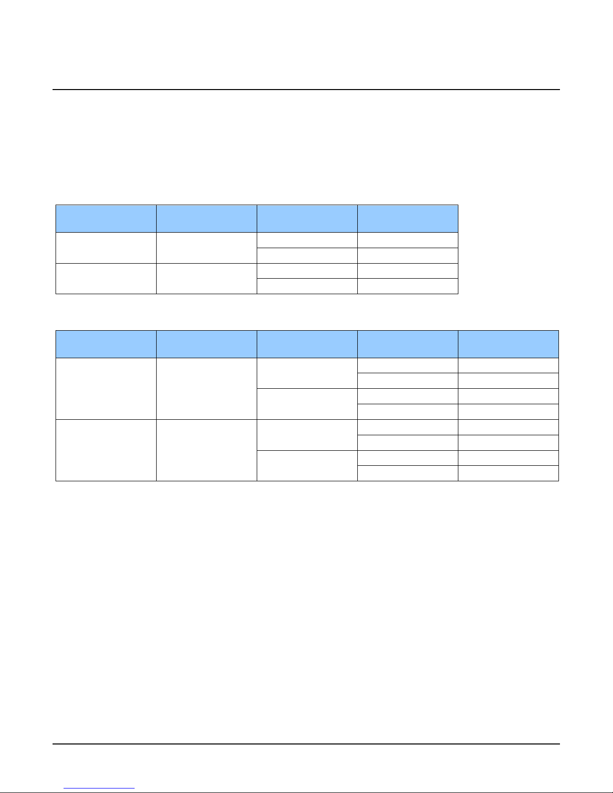
Part Numbers and Software Requirements
This manual covers the Genie Nano monochrome and color models summarized below. This table
groups models by color mode, resolution, and other physical parameters. New models area added
to this manual as they are released by Teledyne DALSA. See Genie Nano Common Specifications
for details of each Genie Nano model.
Monochrome Cameras
Model
Resolution
M1940
1936 x 1216
M1920
1936 x 1216
Color Cameras
Model
Resolution
C1940
1936 x 1216
C1920
1936 x 1216
Sensor Model Lens Part Number
Sony IMX174
Sony IMX249
Sensor Model Lens Part Number
Sony IMX174
Sony IMX249
C-mount
CS-mount
C-mount
CS-mount
C-mount
CS-mount
C-mount
CS-mount
G3-GM10-M1940
coming soon
G3-GM11-M1920
coming soon
G3-GC10-C1940
TBA with IR Filter
coming soon
TBA with IR Filter
G3-GC11-C1920
TBA with IR Filter
coming soon
TBA with IR Filter
Notes
Nano Series GigE Vision Camera Genie Nano Series Overview • 7
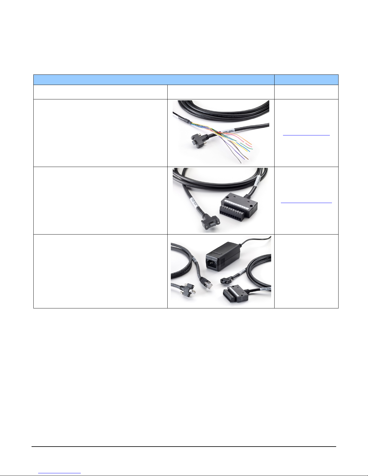
Accessories
Nano Accessories & Cables (sold separately) Order Number
Mounting Bracket Plate, with 1/4 inch s cr e w mount
(tripod mount)
G3-AMNT-BRA00
I/O Blunt End Cable
(2 meter Screw Retentio n to Flying Le ads )
I/O Breakout Cable
(2 meter Screw Retentio n to Euroblock connector)
Power and Cable Evaluation Kit
• Includes a Power Supply (12V),
• an Ethernet Cable (RJ-45, 2 meter),
• and a 2 meter I/O Breakout Cable (Euroblock)
G3-AIOC-BLUNT2M
G3-AIOC-BRKOUT2M
G3-ACBL-EVALKIT
8 • Genie Nano Series Overview Nano Series GigE Vision Camera
Teledyne DALSA Development Software
Teledyne DALSA Software Platform for Microsoft Windows
Sapera LT version 8.01 or later (for Windows)
includes Sapera Network Imaging Packag e and Gig E Vision Imaging
Driver, Sapera Runtime and CamExpert.
Provides everything you will need to develop im aging appl ications
Sapera documentation in compiled HTML help, a nd Adobe Acrobat® (PD F)
Sapera Processing Imaging Developm e nt Libr ary
(available for Windows or Linux - sold separ a te ly):
Teledyne DALSA Software Platform for Linux
GigE-V Framework (fo r both X86 or Arm ty pe processor) Contact Teledyne DALSA Sales
Available for download
http://www.teledynedalsa.com/imaging/support/
Contact Teledyne DALSA Sales
Third Party GigE Vision Development
Third Party GigE Vision Software Platform Requirements
Support of GenICam GenApi version 2.3 General acquisition and control
Support of GenICam GenApi version 2.3 File access: firmware, configuration data, upload &
Support of GenICam XML schema version 1.1
GenICam™ support — XML camera description file Embedded within Genie Nano
download
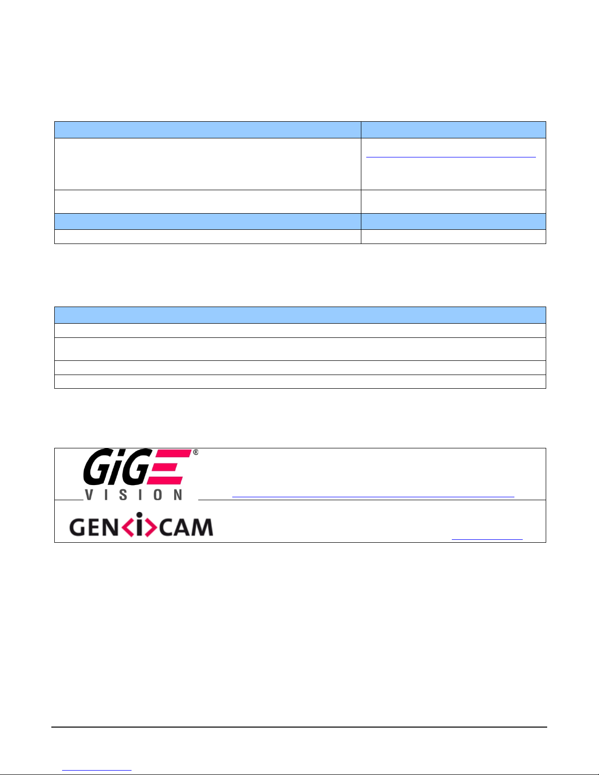
About GigE Vision
Genie Nano cameras are 100% compliant with the GigE Vision 1.2
specification which defines the communic a tio n inte rface protocol used by any
GigE Vision device. The device descriptio n and capabilities are contained in an
XML file. For more information see:
http://www.machinevisiononline.org/public/articles/index.cfm?cat=167
Genie Nano cameras implement a superset of the GenICam™ specif ication
which defines device capabilities. This description takes the form of an XML
device description file respec ting the sy ntax d efi ne d by the GenAp i module of
the GenICam™ specification. For more infor ma tio n see www.genicam.org
The Teledyne DALSA GigE Vision Module provides a license free development platform for Teledyne
DALSA GigE hardware or Sapera vision applications. Additionally supported are Sapera GigE Vision
applications for third party hardware with the pur chase of a GigE Vision Module license, or the
Sapera processing SDK with a valid license.
The GigE Visio n Compliant X ML dev ice description file is embedded within Genie Nano firmware
allowing GigE Visio n Compliant applications access to Genie Nano capabilities and controls
immediately after connection.
.
Nano Series GigE Vision Camera Genie Nano Series Overview • 9

Genie Nano Common Specifications
Model and Sensor specific specificat ions follow the common specifications present here.
Camera Controls
Synchronization Modes Free running, External triggered , Software trigger through Ethernet
Exposure Mode s Programmable in increments of 1µs
Trigger Inputs Opto-isolated, 2.4V to 24V typical, 16mA min.
Strobe Outputs
Features
Image Buffer 90 MB total on-board memory for acquisitions and packet resend buffering
Gain In Sensor gain (model dependent) and Digital gain up to 4x
Counter and Timer 1 Counter, and 1 Timer.
Timestamp 1µs internal timer to timestamp images and eve nts
Test image Internal generator with choice of static and shifting patterns
User settings Select factory default or either of two user saved camera configurations
TurboDrive Technology Currently supported when us ing 8 -bit pixel for mat (Sapera 8. 01 or later)
Back Focal Distance
C-mount models 17.52 mm
CS-mount models 12.52 mm
Mechanical Interface
Camera (L x H x W)
see Mechanical Specifications
Mass 46g (C-mount with no lens)
Power connector via 10-pin connector, or RJ45 in PoE mode
Ethernet connector RJ45
Electrical Interface
Input Voltage +10 to +36 Volts DC (+10%/- 10%)
Power Dissipation (typical) 3.99W @12V / 3.96 @24V / 4.22 @48V / 4.1W with POE
Ethernet Speed Gigabit Ethernet 1000Mbps (10/100Mbps are not supported)
Ethernet Option supported PAUSE Frame support (as per IEEE 802.3x)
Data and Control GigE Vision 1.2 compliant
Environmental Conditions
Operating Temperature -20°C to +60°C (Housing Temperature)
Operating Relative Humid ity 10% to 70% non-condensing
Storage -40°C to +80°C temperature at 20% to 80% non-condensing relative humidity
minimum (in µs) is model specific
maximum is 16 seconds
Pulse controlled via Trigger pulse width.
Debounce range from 0 up to 255 µs
Trigger Delay fro m 0 to 2 , 000,000 µs
Output opto-isolated:
Aligned to the start of exposure with a programmable delay, duration and polarity
(using “start of exposure on output line source” feature)
User programmable, acquisition ind epe ndent, with event generation.
21.2 mm x 29 mm x 44 mm (without lens mount or connectors)
38.9 mm x 29 mm x 44 mm (with C-mount and connectors)
+9 to +56 Volts DC (Absolute min/max Range) on Auxiliary c o nnector
Supports the Power Over Ethernet standard. (PoE Class 3 as per IEEE 802.3af)
10 • Genie Nano Series Overview Nano Series GigE Vision Camera

EMI, Shock and Vibration Certifications
Compliance Directives Standards ID Overview
EN61000-4-2 : 2008 Electrostatic discharge im munity te s t
EN61000-4-3 : 2006 A1 : 2007 A2 :
2010
EN61000-4-4 : 2004 Electrical fast transient/burst immunity test
EN61000-4-5 : 2005 Surge immunity
EN61000-4-6 : 2008 Immunity to conducted disturbances, induced by
CE
FCC
RoHS
For an image of Genie Nano certificates see "EC & FCC Declarations of Conformity" on page 96
EN61000-4-8 : 2009 Power frequency magnetic field immunity
EN61000-4-11 : 2004 V o lta g e variati o ns im munity
EN61000-6-2 : 2005 Electromagnetic immunity
EN61000-6-4: 2007 Electromagnetic emissions
CISPR 11: 2009 A1 :
group 1 FCC, part 15, subp art B :20 10
CISPR 22 : 2008 Limit: class A LAN port Conducted Emissions
Part 15, class A
Compliancy as per European directive 2011/65/EC
Vibration & Shock Tests Test Levels (while operating) Test Parameters
Random vibrations
Shocks
Level 1: 2 grms 60 min.
Level 2: 4 gr ms 45 min.
Level 3: 6 grms 30 min.
Level 1: 2 0 g / 11 ms
Level 2: 3 0 g / 11 ms
Level 3: 4 0 g / 60 ms
Additional information concerning test conditions and methodologies is available on request.
Radiated, radio-frequency, electromagnetic field
immunity test
radio-frequency fields
Limit: class A Conducted Emissions
Frequency rang e : 5 to 2000 Hz
Directions: X, Y, and Z axes
Shape: half-sine
Number: 3 shocks (+) and 3 shocks (-)
Directions: ±X, ±Y, and ±Z axes
Nano Series GigE Vision Camera Genie Nano Series Overview • 11
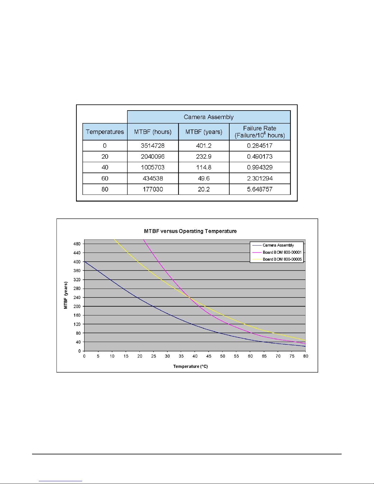
Mean Time Between Failure (MTBF)
The analysis was carried out for operating temperatures varying from 0 to 80ºC, with the product
steady state temperature determined as 20ºC. The follow ing tab le presents the predicted MTBF and
failure rate values.
12 • Genie Nano Series Overview Nano Series GigE Vision Camera

Model Specifications: M/C1940 & M/C1920
Model specific specifications and response graphics are provided here. The response curves
describe the sensor, excluding lens and light source characteristics.
Supported Features
M1920 C1920 M1940 C1940
Minimum Frame Rate
(internal acquisition)
Maximum Frame Rate
(full resolution – 1936x1216)
Maximum Frame Rate Output System dependent on the GigE network (based on typical 115 MBs of image data)
Pixel Data Formats Monochrome 8-bit
Sensor Exposure Time Minimum 1 line time + 13.73 us = 34.23 µs
Horizontal Line Time 20.5 µs 9.5 µs
Exposure Time Maximum ~16 sec
End of Exposure to Start of
Readout
Readout Time Horizontal Line Time (max) x (lines in full frame +20) — in μs
Exposure Control
Internal Trigger to Start of
Exposure
External Exposure Control (1 line time + 13.73 us)
Gain Control In-Sensor Gain: 48dB range
Black Offset Control Yes (0 to 511 dn)
Monochrome 12-bit
auto-adjusted to steps of 20.5 µs
(3 line time with initial beta version 1.00 )
25 lines (512.5µs) 25 lines (237.5µs)
Internal - Programmable via the camera API
External – based on Trigger Width
2 to 3 line time
up to 24dB as analog gain in 0.1 dB steps (1x to 15x)
from 24dB to 48dB as digital gain in 0.1 dB steps (from 16x to 250x )
Additional Digital Gain: 4x (monochrome models only, color models TBA)
0.06 fps 0.06 fps
38.8 fps 83.9 fps (with TurboDr ive)
Bayer 8-bit
Bayer 12-bit
Camera Models
Monochrome 8-bit
Monochrome 10-bit
1 line time + 13.73 us = 23.23 µs
auto-adjusted to steps of 9.5 µs
(3 line time with initial beta version 1.00)
Bayer 8-bit
Bayer 10-bit
Multi-ROI Support TBA Yes — In-Sensor
Synchronization Via External Trigger Signal Or Internal Tr igg er Free Run
Data Output Gigabit Ethernet (~115MB/sec max)
Pixel Size 5.86 µm x 5.86 µm
Shutter Full frame electronic global shutter function
Full Well charge 32 ke (max)
Output Dynamic Range † ‡
Signal to Noise ratio †† ‡ 43.9 dB typical
DN Variation 50 % satur a tio n: < +/- 0.5%
Responsivity see graphic:
75.5 dB (12-bit), 68.3 dB (10-bit)
Nano Series GigE Vision Camera Genie Nano Series Overview • 13

† Dynamic Range Test Conditions
• Exposure 100µs
• 0% Full Light Level
†† SNR Test Conditions
• Exposure 2000µs
• 80% saturation
‡ Specifications calculated according to EMVA-1288 standard, using white LED light
Sensor Cosmetic Specifications
Blemish Specifications Maximum Number of
Defects
Hot/Dead Pixel defects ††† Typical 0.0025%
Max 0.005%
Spot def ects none Grouping of more than 8 pixel defects within a sub-area of 3x3
Clusters defects none Grouping of more than 5 single pixel defects in a 3x3 kernel.
Column defects none Vertical grouping of more than 10 contiguous pixel defects along
Row defects none Horizontal grouping of more than 10 contiguous pixe l defects
Blemish Description
Any pixel that deviates by ±20% from the average of
neighboring pixels at 50% saturation includ ing pixel stuck at 0
and maximum saturated value.
pixels, to a maximum spot size of 7x7 pixels.
a single column.
along a single row.
††† Test conditions
• Nominal light = illumination at 50% of saturation
• Temperature of camera is 45°C
14 • Genie Nano Series Overview Nano Series GigE Vision Camera
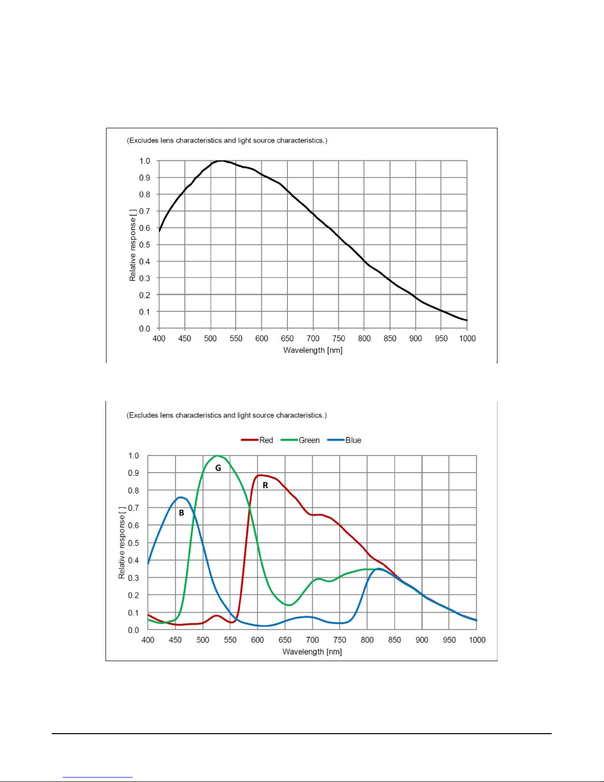
Spectral Response
Monochrome Models M194x & M192x, (Sony IMX174 & IMX249)
Measured Fill-Factor x Quantum Efficiency (FF x QE)
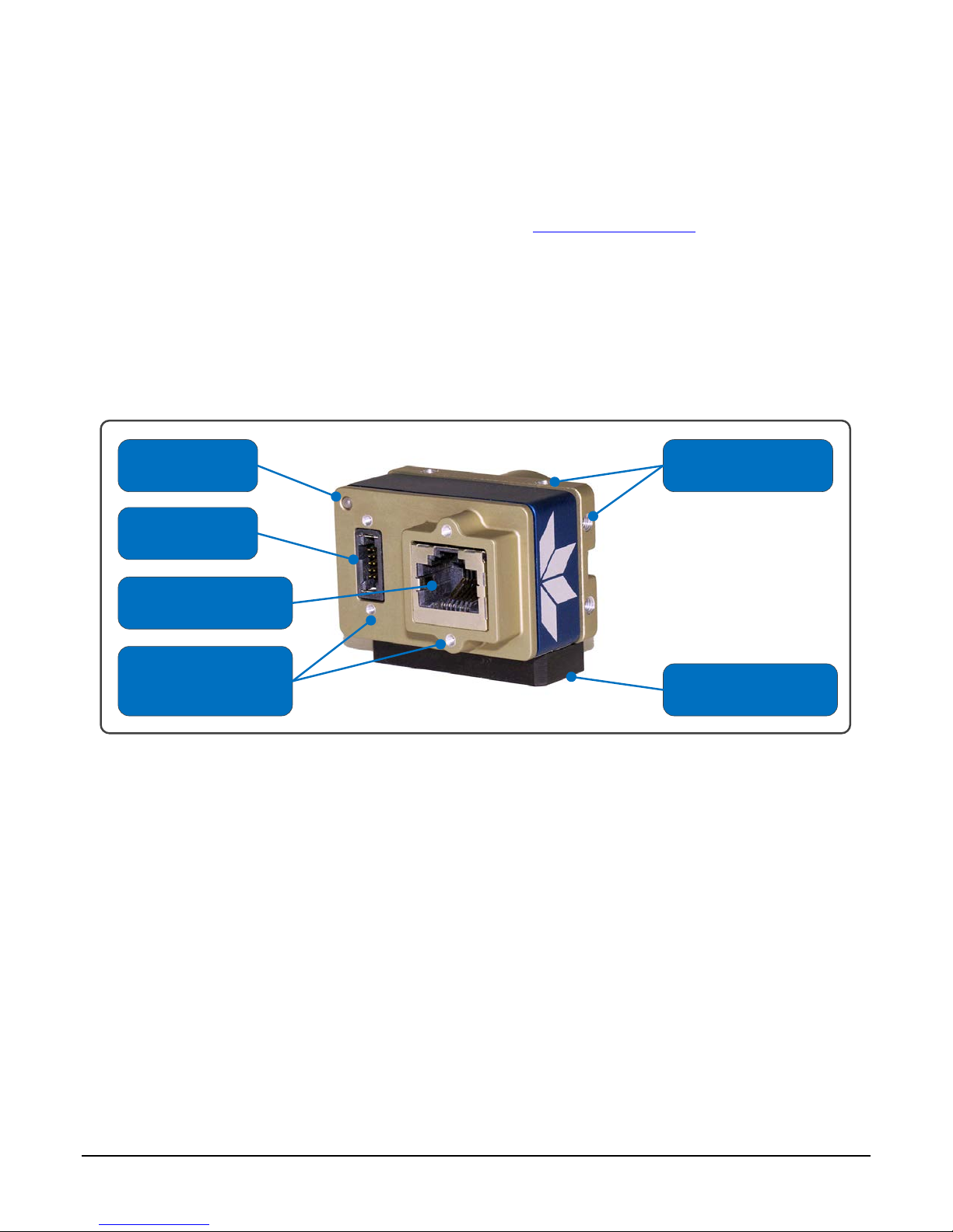
Color Models C194x & C192x, (Sony IMX174 & IMX249)
Measured Fill-Factor x Quantum Efficiency (FF x QE)
Nano Series GigE Vision Camera Genie Nano Series Overview • 15

Nano Quick Start
If you are familiar with GigE Vision cameras follow these steps to quickly install and acquire images
with Genie Nano and Sapera LT in a Windows OS system. If you are not familiar with Teledyne
DALSA GigE Vision cameras go to Connecting the Genie Nano Camera.
• Your computer requires a second or unused Ethernet Gigabit network interface (NIC).
• Install Sapera 8.01 and make certain to select the installation of GigE Vision support.
• Connect Nano to the spare NIC and wait for the GigE Server Icon in the Windows tray to show
that the Nano is conne cted. The Nano Status LED will be steady Blue.
If you have no lens on the Nano
• Start CamExpert. The Nano Status LED will be steady Green.
• Select the moving test pattern from the Image Format Feature Category.
• Click grab
If you have a lens on the Nano
• Start CamExpert. The Nano Status LED will be steady Green.
• Click the button to show a full camera image on CamExpert display.
• Click grab.
• Adjust the lens aperture and/or adjust the Nano Exposure as required.
Camera Works–Now What
Consult this manual for detailed Networking and N a no feature descriptions, as you write, debug,
and optimize your imaging application.
16 • Nano Quick Start Nano Series GigE Vision Camera

Connecting the Genie Nano
Camera
GigE Network Adapter Overview
Genie Nano connects to a computer’s Gigabit Network Adapter. If the computer is already
connected to a network, the computer requires a second network adapter, either onboard or an
additional PCIe NIC adapter. Refer to the Te ledyne DALSA Ne twork Imaging manual for information
on optimizing network adapters for GigE Vision cameras.
PAUSE Frame Support
The Genie Nano supports the Gigabit Ethernet PAUSE Frame feature as per IEEE 802.3x. PAUSE
Frame is the Ethernet flow control mechanism to manage network traffic within an Ethernet switch
when multiple cameras are simultaneously used. This requires that the flow control option in the
NIC property settings and the Ethernet switch settings must be enabled. Refer to the Teledyne
DALSA Network Imaging manual.
Connect the Genie Nano Camera
Connecting a Genie Nano to a network system is similar whether using the Teledyne DALSA Sapera
LT package or a third party GigE Vision development package.
• Power supplies must meet the requirements defined in section Input Signals Electrical . Apply
power to the camera.
• Connect Nano to the host computer GigE network adapter or to the Ethernet switch via a CAT5e
or CAT6 Ethernet ca b le. Note: cable should not be less than 1 meter (3 feet) long or more than
100 meters (328 feet) long.
• Once communication with the host computer is started the automatic IP configuration sequence
will assign an LLA IP address as described in section Genie Nano IP Configuration Sequence, or
a DHCP IP address if a DHCP server is present on your network.
• Check the status LED which will be initially red then switch to flashing blue while waiting for IP
configuration. See Camera Status LED for Nano LED display descriptions.
• The factory defaults for Nano is Persistent IP disabled and DHCP enabled with LLA always
enabled as per the GigE Vision specification. For additional information see Nano IP
Configuration Mode Details. See the next section Connectors for an overview of the Nano
interfaces.
Nano Series GigE Vision Camera Connecting the Genie Nano Camera • 17
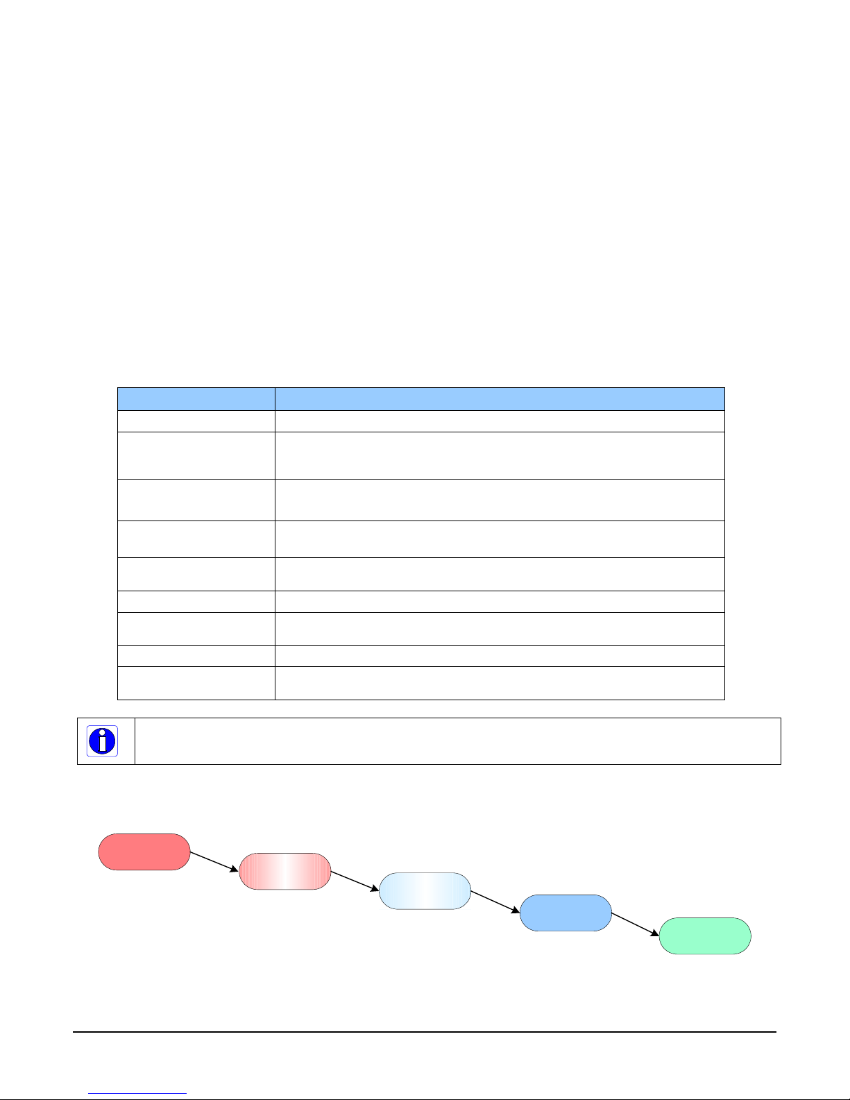
Connectors
Status LED
10
Pin
I/
O &
Power
Ethernet Connector
(supports PoE
)
Supports
Thumbscrew
Secured Cables
Camera Mounts
(
4
sides
)
Optional Tripod
Mount
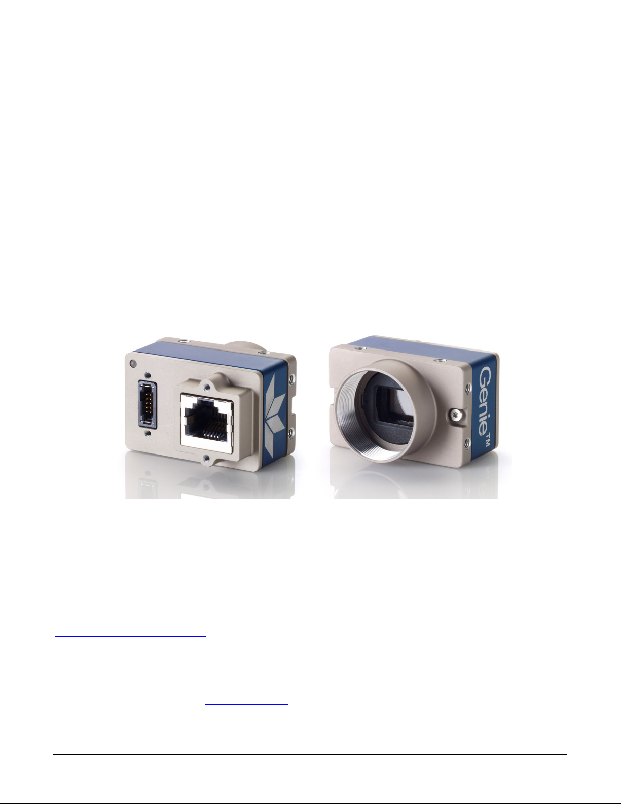
The Nano has two connectors:
• A single RJ45 Ethernet connector for control and video data transmitted to/from the host
computer Gigabit NIC. The Genie Nano also supports Power Over Ethernet
See Ruggedized RJ45 Ethernet Cables for secure cables.
• A 10 pin I/O connector for camera power, plus trigger, strobe and general I/O signals. The
connector support s a ret ention latch, while the Nano case supports thumbscrews. Teledyne
DALSA provides optional cables (see Accessories). See 10-pin I/O Con n ect o r D et ails for
connector pin out specifications.
The following figure of the Genie Nano back end shows connector and LED locations. See
Mechanical Specifications for details on the connectors and camera mounting dimensions.
(PoE).
18 • Connecting the Genie Nano Camera Nano Series GigE Vision Camera
Genie Nano – Rear View
Flashing Red
initialization
Flashing Blue
waiting for IP
Blue
IP assigned
Green
application
connected
Red
power connected
LED Indicators
The Genie Nano has one m ultico lor LED to provide a simple visible indication of camera state, as
described below. The Nano Ethernet connector does not have indicator LEDs; the user should use
the LED status on the Ethernet switch or computer NIC for networking status.
Camera Status LED Indicator
The camera is equipped with one LED to display its operational status. When more than one
condition is active, the LED color indicates the condition with the highest priority (such as, an
acquisition in progress has more priority than a val id IP address assignment).
Once the Genie Nano connects to a network and an IP address is assigned, the Status LED will turn
to steady blue. Only at this time will it be possible by the GigE Se rver or any application to
communicate with the camera. The following table summarizes the LED states and corresponding
camera status.
LED State Definition
LED is off
Steady Red
Flashing Red
Steady Red +
Flashing Blue
Slow Flashing Blue
Fast Flashing Bl ue
Steady Blue
Steady Green
Flashing Green
Note: Even if the Nano has obtained an IP address, it might be on a different subnet than the NIC it is attached
to. Therefore, if the Nano LED is blue but an application cannot see it, this indicates a network configuratio n
problem. Review troubleshooting suggestions in the Network Imaging manual.
No power to the camera
Initial state on power up before flashing.
Remains as steady Red only if there is a fatal error.
Camera is not initialized **
Initialization sequence in progre s s
Wait less than a minute for the Nano to reboo t its e lf.
**
Fatal Error. If the Genie Nano does not reboot itself contact Technical
Support.
Ethernet cable disconnected. The camera continuously attempts to assign
itself an IP address.
File Access Feature is transferring data such as a firmware update, etc.
IP address assigned;
no application connected to the camera
Application connected
Acquisition in progress. Flashing occurs on frame acquisition but does not
exceed a rate of 100ms for faster frame rates.
LED States on Power Up
The following LED sequence occurs when the Genie Nano is powered up connected to a network.
Nano Series GigE Vision Camera Connecting the Genie Nano Camera • 19

Genie Nano IP Configuration Sequence
The Genie Nano IP (Internet Protocol) Configuration sequence to assign an IP addre ss is executed
automatically on camera power-up or when connected to a network. As a GigE Vision compliant
device, Nano attempts to assign an IP address as follows.
For any GigE Vision device, the IP configuration protocol sequence is:
• Persistent IP (if enabled)
• DHCP (if a DHCP server is present such as the Teledyne DALSA Smart DHCP server)
• Link-Local Address (always enabled as default)
The factory defaults for Nano is Persistent IP disabled and DHCP enabled with LLA always enabled
as per the GigE Visio n specification. F or additional information see Nano IP Configuration Mode
Details.
Supported Network Configurations
The Genie Nano obtains an IP address using the Link Local Address (LLA) or DHCP, by default. If
required, a persistent IP address can be assigned (refer to the Network Imaging manual).
Preferably, a DHCP server is present on the network, where the Genie Nano issues a DHCP request
for an IP address. The DHCP server then provides the Nano an IP address. The Teledyne DALSA
Network Configuration tool, installed with the Sapera Teledyne DALSA Network Imaging
Package, provides a DHCP server which is easily enabled on the NIC used with the Genie Nano
(refer to the Teledyne DALSA Network Imaging user's manual).
The LLA method, if used, automatically assigns the Nano with a randomly chosen address on the
169.254.xxx.xxx subnet. After an address is chosen, the link-local process sends an ARP query
with that IP onto the network to see if it is already in use. If there is no response, the IP is
assigned to the device, otherwise another IP is selected, and the ARP is repeated. Note that the
LLA mode is unable to forward packets across routers.
20 • Connecting the Genie Nano Camera Nano Series GigE Vision Camera
Preventing Operational Faults due to ESD
Nano camera installations which do not protect agains t ESD (electrostatic
discharge) may exhibit operational faults. Problems such as random packet loss,
random camera resets, and random loss of Ethernet connections, may a ll b e
solved by proper ESD management.
The Nano camera when used with a simple power supply and Ethernet cable, is
not properly connected to ear th ground and therefore is s usceptible to ESD
caused problems. An Eth ern et ca ble has no ground connection and a power
supply's 0 volt return line is not ne c e s s arily connected to ea r th ground.
Teledyne DALSA has performed ESD testing on Nano cameras using an 8 kilovolt ESD generator
without any in dication of operational faults. The two following metho ds, either individually o r
together will prevent ESD problems.
• Method 1: Use a shielded/grounded power supply that connects ground to pin-10 of the I/O
connector. The Nano case is now properly connected to earth ground and can withstand ESD of
8 kilovolts, as tested by Teledyne DALSA.
• Method 2: When using Power Over Ethernet (PoE), Teledyne DALSA strongly recommends using
a shielded Ethernet cable to provide a ground connection from the controlling computer/power
supply, to the Genie Nano. PoE requires a powered computer NIC, or a powered Ethernet
switch, or an Ethernet power injector.
• Method 3: Mount the camera on a metallic platform with a good connection to earth ground.
Nano Series GigE Vision Camera Connecting the Genie Nano Camera • 21

Using Nano with Sapera API
A Genie Nano camera installation with the Teledyne DALSA Sapera API generally follows the
sequence described below.
Network and Computer Overview
• Nano needs to connect to a computer with a GigE network adapter, either built in on the
computer motherboard or installed as a third party PCI adapter. See the previous section
Connecting the Genie Nano Camera.
• Laptop computers with built in GigE network adapters may still not be able to stream full
frame rates from Nano, especially when on battery power.
• Nano also can connect through a Gi gabit Ethernet switch. When using VLAN groups, the
Nano and controlling computer must be in the same group (refer to the Teledyne DALSA
Network Imaging Package user's manual).
• If Genie Nano is to be used in a Sapera development environment, Sapera LT 8.10 needs to
be installed, which includes the GigE Vision Module software package with the Teledyne
DALSA GigE Vision TurboDrive Technology module.
• If Genie Nano will be used in a third party GigE Vision Compliant environment, Sapera or
Sapera runtime is not required and you need to follow the installation instructions of the third
party package.
• The Windows Firewall exceptions feature is automatically configured to allow the Sapera GigE
Server to pass through the firewall.
• Computers with VPN software (virtual private network) may need to have the VPN driver
disabled in the NIC properties. This would be required only on the NIC used with the Nano.
Testing by the user is required.
• Once a Nano is connected, look at the small camera icon added to the Windows tray (next to
the clock). Ensure the Nano camera has been found (right click the icon and select Status) Note
that in Windows 7, the icon remains hidden until a cam era is connected.
• A new Nano installation may require a firmware upd at e. The File Selector
select a firmware file. See the CamExpert procedure Updating Firmware via File Access in
CamExpert for additiona l in f ormat io n .
• Use CamExpert (installed either with Sapera or Sapera runtime) to test the installation of the
Nano camera. Set the Nano to internal test pattern. See Internal Test Pattern Generator.
• Set up the other components of the imaging system such as light sources, camera mounts,
optics, encoders, trigger sources, etc. Test with CamExpert.
feature is used to
22 • Using Nano with Sapera API Nano Series GigE Vision Camera

Installation
Note: to install Sapera LT and the GigE Vision packa ge, log on to the works tati o n as an administrator or
with an account that has administrator privile ges.
When Genie Nano is used in a Sapera development environment, Sapera LT 8.01 needs to be
installed, which automatically provides all GigE Vision camera suppo rt including TurboDrive.
If no Sapera development is required. then the Sapera LT SDK is not needed to control the
Linea GigE camera. Sapera runtime with CamExpert provides everything to control the camera.
Procedure
• Download and install Sapera 8.01 which automatically provides GigE Vision support with
Teledyne DALSA T u rboDrive™ techn ology.
• Optional: If the Teledyne DALSA Sapera LT SDK package is not used, click to install the Genie
Nano firmware and user manuals only. Follow the on screen prompts.
• Connect the camera to an available free Gigabit NIC.
Refer to Sapera LT User’s Manual concerning application development with Sapera.
Note: The Teledyne DALSA Sapera CamExpert tool (used throughout this manual to describe Genie Nano
features) is installed with either the Sapera LT runtime or the Sapera LT development package.
Camera Firmware Updates
Under Windows, the user can upload new firmware, downloaded from Teledyne DALSA support,
using the File Access Control
features provided by the Sapera CamExpert tool.
Firmware via Linux or Third Party Tools
Consult your third party GigE Vision software package for file uploads to the connected device.
Nano Series GigE Vision Camera Using Nano with Sapera API • 23
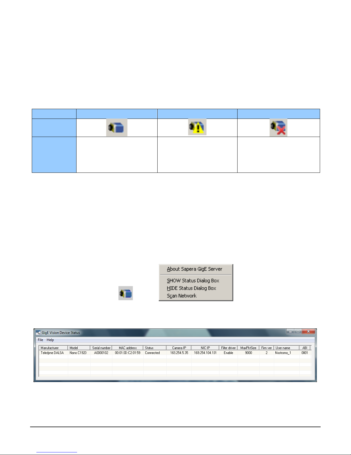
GigE Server Verification
After a successful Genie Nano Framework package installation, the GigE Server icon is visible in the
desktop taskbar tray area (note that in Windows 7 the icon remains hidden until a came ra is
connected). After connecting a camera (see following section), allow a few seconds for the GigE
Server status to update. The Nano camera must be on the same subnet as the NIC to be
recognized by the GigE Server.
Device Available Devic e IP Error Device Not Available
GigE Server
Tray Icon:
The normal GigE server tray
icon when the Genie device is
found. It will take a few
seconds for the GigE Server to
refresh its state after the Genie
has obtained an IP address.
The GigE server tray icon
shows a warning when a device
is connected but there is some
type of IP error.
A red X will remain over the
GigE server tray icon when the
Genie device is not found. This
indicates a major network issue.
Or in the simplest case, the
Genie is not connected.
If you place your mouse cursor on this icon, the GigE Server wil l display the number of GigE Vision
devices found by your PC. Right click the icon and se lect status to view information about those
devices. See Troubleshooting for more information.
GigE Server Status
Once the Genie Nano is assigned an IP address (its Status LED is steady blue) the GigE server tray
icon will not have a red X through it, indica ting that the Nano device was found. It might take a few
seconds for the GigE Server to refresh its state after the Nano has obtained an IP address.
Right-click the GigE Server tray icon to open the following menu.
Click on Show Status to open a window listing all devices connected to the host system. Each GigE
device is listed by name along with important information such as the assigned IP address and
device MAC address. The screen shot below shows a connected Nano with no networking problems.
In the event that the device is physically connected, but the Sapera GigE Server icon is indicating
that the connected device is not recognized, click Scan Network to restart the discovery process.
Note that the GigE server periodically scans the network automatically to refresh its state. See
Troubleshooting for network problems.
24 • Using Nano with Sapera API Nano Series GigE Vision Camera

Optimizing the Network Adapter used with Nano
Most Gigabit network interface controllers (NIC) allow user modifications to parameters such as
Adapter Buffers and Jumbo Frames. These should be optimized f or use with the Nano during the
installation. Refer to the Teledyne DALSA Network Imaging package manual for optimization
information using the Network Configuration Tool.
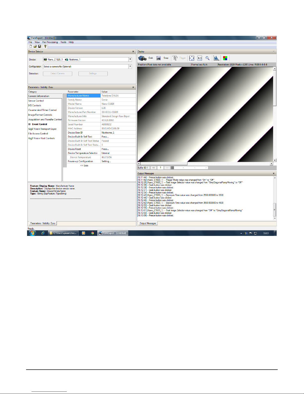
Quick Test with CamExpert (Windows)
When the Genie Nano camera is connected to a Gigabit network adapter on a host computer,
testing the installation with CamExper t is a straightforward procedure.
• Start Sapera CamExpert by double clicking the desktop icon created during the software
installation.
• CamExpert will search for installed Sapera devices. In the Device list area on the left side, the
connected Nano camera is shown or will be listed in a few seconds after CamExpert completes
the automatic device search (device discovery).
• Select the Nano camera device by clicking on the camera user defined name. By default the
Nano camera is identified by its serial number. The Nano status LED will turn green, indicating
the CamExpert application is now connected.
• Click on the Grab button for live acquisition (the Nano default is Free Running mode). Focus
and adjust the lens iris. See Operational Reference for information on CamExpert parameters
with the Nano camera.
• If the Nano has no lens, just select one of the internal test patterns available (Image Format
Controls – Test Image Selector). All but one are static images to use with the Snap or Grab
function of CamExpert. The single “moving” test image is a shifting d ia g onal ramp pattern,
which is useful for testing network/computer bandwidt h issue s (s e e fo llowing im a g e ) .
• Refer to the Teledyne DALSA Network Imaging package manual if error messages are shown in
the Output Messages pane while grabbing.
Nano Series GigE Vision Camera Using Nano with Sapera API • 25
26 • Using Nano with Sapera API Nano Series GigE Vision Camera

About the Device User ID
The Nano can be programmed with a user defined name to aid identifying multiple cameras
connected to the network. For instance, on an inspection system with 4 cameras, the first camera
might be labeled “top view”, the second “left view”, the third “ right view” and the last one “bottom
view”. The factory default user name is set to match the camera serial number for quick initial
identification. Note that the factory programmed Genie Nano serial number and MAC address are
not user changeable.
When using CamExpert, multiple Genie Nano cameras on the network are seen as different
"Nano-xxxxx" devices as an example. Non Teledy ne DALSA came ras are labeled as “GigEVis ion
Device”. Click on a device user name to select it for control by CamExpert.
An imaging application uses any one of these attributes to identify a camera: its IP address, MAC
address, serial number or User Name. Some important considerations are listed below.
• Do not use the camera's IP address as identification (unless it is a persistent IP) since it can
change with each power cycle.
• A MAC address is unique to a single camera, therefore the control application is limited to the
vision system with that unique camera if it uses the camera's MAC address.
• The User Name can be freely programmed to clearly represent the camera usage. This scheme
is recommended for an application to identify cameras. In this case, the vision system can be
duplicated any number of times with cameras identified by their function, not their serial
numbers or MAC address.
Nano Series GigE Vision Camera Using Nano with Sapera API • 27
Operational Reference
Using CamExpert with Genie Nano Cameras
The Sapera CamExpert tool is the interfacing tool for GigE Vision cameras, and is supported by the
Sapera library and hardware. CamExpert allows a user to test camera functions. Additionally
CamExpert saves the Nano user settings configuration to the camera or saves multiple
configurations as individual camera parameter files on the host system (*.ccf).
An important component of CamExpert is its live acquisition display window which allows
immediate verification of timing or control parameters without the need to run a separate
acquisition program.
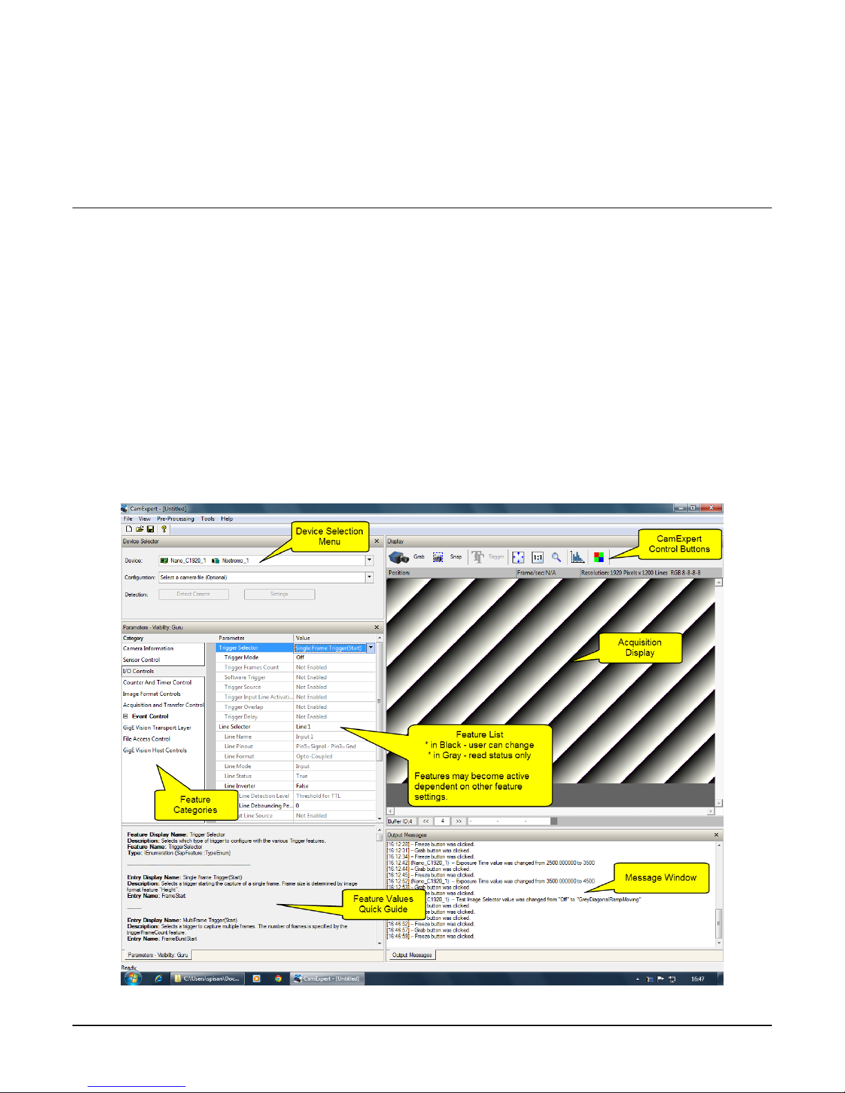
CamExpert Panes
The various areas of the CamExpert tool are described in the summary figure below. GigE Vision
device Categories and Parameter features are displayed as per the device’s XML description file.
The number of parameters shown is dependent on the View mode selected
(i.e. Beginn er, Expert, Guru – see description below).
28 • Operational Reference Nano Series GigE Vision Camera
 Loading...