

Teledyne Genie C640-1/2, Genie C640-1/3, Genie C1024-1/3, Genie C1280-1/3, Genie C1400-1/2 User Manual
...
Genie Color Series
Camera User’s Manual
Genie Framework 2.01
C640, C1024, C1280, C1400, C1410, C1600
™
sensors |
cameras
| frame grabbers | processors | software | vision solutions
P/N: CA-GENM-NM-CUM00
www.teledynedalsa.com

Notice
© 2013 – 2015 Teledyne DALSA
All information provided in this manual is believed to be accurate and reliable. No
responsibility is assumed by Teledyne DALSA for its use. Teledyne DALSA reserves the right
to make changes to this information without notice. Reproduction of this manual in whole or
in part, by any means, is prohibited without prior permission having been obtained from
Teledyne DALSA.
Microsoft and Windows are registered trademarks of Microsoft Corporation in the United
States and other countries. Windows, Windows Vista, Windows 7, W indows 8 and Windows
8.1 are trademarks of Microsoft Corporation.
All other trademarks or intellectual property mentioned herein belong to their respective
owners.
Document Date: April 15, 2015, 2015
Document Number: CA-GENM-CUM00
About Teledyne DALSA
Teledyne DALSA is an international high performance semiconductor and electronics
company that designs, develops, manufactures, and markets digital imaging products and
solutions, in addition to providing wafer foundry s ervices.
Teledyne DALSA Digital Imaging offers the widest range of machine vision components in
the world. From industry-leading image sensors through powerful and so p histicate d
cameras, frame grabbers, vision processors and software to easy-to-use vision appliances
and custom vision modules.

Contents
GENIE COLOR SERIES OVERVIEW .................................................................. 5
DESCRIPTION ................................................................................................ 5
Genie Application Advantages .................................................................. 6
PRODUCT PART NUMBERS .................................................................................. 6
CAMERA PERFORMANCE SPECIFICATIONS ................................................................ 8
Certifications ......................................................................................... 9
Vibration and Shock Certifications ............................................................ 9
SUPPORTED INDUSTRY STANDARDS .................................................................... 10
GENIE SENSOR OVERVIEW ............................................................................... 10
Genie C640-1/2 Specifications ............................................................... 11
Genie C640-1/3 Specifications ............................................................... 13
Genie C1024-1/3 Specifications .............................................................. 15
Genie C1280-1/3 Specifications .............................................................. 17
Genie C1400-1/2 Specifications .............................................................. 19
Genie C1410-2/3 Specifications .............................................................. 21
Genie C1600-1/1.8 Specifications ........................................................... 23
APPLICATION DEVELOPMENT OVERVIEW ............................................................... 24
Sapera LT Library with optional Processing .............................................. 24
GigE Vision Compliant Environment ........................................................ 24
INSTALLING THE GENIE CAMERA ................................................................ 25
WARNING! (GROUNDING INSTRUCTIONS) ............................................................. 25
GIGE NETWORK ADAPTER GUIDELINE .................................................................. 25
Supported Network Configurations ......................................................... 25
INSTALLATION OVERVIEW & PREPARATIONS .......................................................... 26
Network and Computer Overview ........................................................... 26
Installation Overview ............................................................................ 27
Preventing Operational Faults due to ESD ................................................ 27
SAPERA LT LIBRARY INSTALLATION ..................................................................... 28
GENIE CD PACKAGE INSTALLATION..................................................................... 28
Procedure ............................................................................................ 28
GigE Server Verification ........................................................................ 29
CONNECT THE GENIE CAMERA ........................................................................... 30
Connectors .......................................................................................... 30
Status LED Codes ................................................................................. 31
Genie IP Configuration Sequence ............................................................ 32
GigE Server Status ............................................................................... 32
OPTIMIZING THE NETWORK ADAPTER USED WITH GENIE ............................................ 33
Running the Network Configuration Tool .................................................. 33
UPDATING GENIE FIRMWARE ............................................................................ 34
QUICK TEST WITH CAMEXPERT .......................................................................... 36
About the User-Defined Camera Name .................................................... 37
SILENT INSTALLATION OF GENIE FRAMEWORK ........................................................ 38
WINDOWS EMBEDDED 7 INSTALLATION ................................................................ 39
OPERATIONAL REFERENCE .......................................................................... 40
CAMERA AND SENSOR INFORMATION ................................................................... 40
Genie Color Series-GigE Vision Camera Contents • 1

Access Via CamExpert ........................................................................... 40
Power-up Configuration (Saved User Settings) ......................................... 41
Camera Information via Sape ra LT or GigE Vision Compliant
Applications .................................................................................... 43
SENSOR CONTROLS ....................................................................................... 44
Sensor Parameters: Controls Via CamExpert ............................................ 44
Color Calibration .................................................................................. 45
Gain and Black Level Controls ................................................................ 46
Gain and Offset Control via Sa pera LT or GigE Vision Co mplia nt
Applications .................................................................................... 47
Partial Scan—Window ROI ..................................................................... 48
Window ROI Control via Sapera LT or GigE Vision Compliant
Applications .................................................................................... 51
CamExpert Image Buffer and ROI Parameters .......................................... 51
TRIGGER MODES .......................................................................................... 52
EXPOSURE CONTROLS .................................................................................... 53
Free-running Programmable Exposure..................................................... 53
External Trigger Programmable Exposure ................................................ 54
External Trigger Level-controlled Exposure .............................................. 56
Exposure Controls via Sapera LT or GigE Vision Compliant Applications ....... 57
SYNCHRONIZATION TIMING .............................................................................. 58
Synchronous M ode ............................................................................... 58
Reset Mode ......................................................................................... 59
Synchronization Mode via Sapera LT or GigE Vision Compliant
Applications .................................................................................... 59
CAMEXPERT I/O CONTROLS DIALOG ................................................................... 60
GENERAL INPUTS .......................................................................................... 62
External Input Signal Opto-coupler & Debounce Circuit ............................. 62
General Inputs: Settings Via CamExpert .................................................. 62
Input Controls via Sapera LT or GigE Vision Compliant Applications ............ 64
STROBE AND GENERAL OUTPUTS ........................................................................ 65
General Outputs: Settings via CamExpert ................................................ 65
Output Control via Sapera LT o r GigE Vision Compliant Applications ............ 70
GENIE PROCESSING FEATURES .......................................................................... 71
Lookup Table (LUT) .............................................................................. 71
LUT Control via Sapera LT or GigE Vision Compliant Applications ................ 72
Flat Field (Image Shading) Corr ection ..................................................... 72
Flat Field Correction Control via Sapera LT or GigE Vision Compliant
Applications .................................................................................... 77
Image Flip ........................................................................................... 78
Internal Image Test Patterns ................................................................. 79
Test Image Select via Sapera LT or GigE Vision Compliant Applic a tions ....... 80
EVENTS ..................................................................................................... 81
Sapera Callbacks .................................................................................. 81
Event Selection via GigE Vision Compliant Applications .............................. 82
USING CAMEXPERT TO SET NETWORK CONTROLS & GIGE VISION PARAMETERS ................ 82
CamExpert GigE Vision Parameters ......................................................... 82
Network Controls via Sapera LT or GigE Vision Compliant Applications ........ 86
SAPERA SUPPORTED FEATURES LIST ................................................................... 87
Accessing Features with Sapera++ LT ..................................................... 87
Feature Type STRING ........................................................................... 88
Feature Type ENUM .............................................................................. 88
Feature Type INT32 .............................................................................. 90
Feature Type BOOL ............................................................................... 92
2 • Contents Genie Color Series-GigE Vision Camera

Feature Summary List by Function Group ................................................ 93
Feature Interdependence Diagrams ........................................................ 97
Accessing the Genie User Buffer ........................................................... 101
NETWORK OVERVIEW & TOOLS ................................................................. 103
GENIE IP CONFIGURATION MODE DETAILS .......................................................... 103
Link-Local Address (LLA) ..................................................................... 103
DHCP (Dynamic Host Configuration Protocol) ......................................... 104
Persistent IP ...................................................................................... 105
SAPERA CAMEXPERT GUIDE ...................................................................... 107
USING CAMEXPERT WITH GENIE COLOR CAMERAS ................................................. 107
CamExpert Panes ............................................................................... 108
CamExpert LUT Controls...................................................................... 109
TECHNICAL SPECIFICATIONS .................................................................... 111
MECHANICAL SPECIFICATIONS ........................................................................ 111
Genie 3D View with C-mount and CS-mount .......................................... 111
Genie C-mount and CS-mount Mechanical Specifications ......................... 112
Genie 3D View with Right-angle C-mount and CS-mount ......................... 113
Genie Right-angle C-mount and CS-mount Mechanical Specifications ........ 114
Additional Notes on Genie Mechanical ................................................... 115
SENSOR ALIGNMENT SPECIFICATION ................................................................. 115
CONNECTORS ............................................................................................ 116
12-Pin Hirose Connector Signal Details .................................................. 116
Genie Signal Electrical Deta ils .............................................................. 117
RJ45 LAN Ethernet Connector Details .................................................... 119
CAMERA STATUS LED .................................................................................. 120
OPTICAL CONSIDERATIONS ............................................................................ 120
Illumination ....................................................................................... 120
Light Sources ..................................................................................... 121
Filters ............................................................................................... 121
Lens Modeling .................................................................................... 121
Magnification and Resolution................................................................ 122
LENS SELECTION OVERVIEW ........................................................................... 122
Lens Mount ........................................................................................ 122
Lens Sensor Size ................................................................................ 123
Additional Lens Parameters (application specif ic) .................................... 124
SENSOR HANDLING INSTRUCTIONS ................................................................... 125
Electrostatic Discharge and the CCD Sensor ........................................... 125
Protecting Against Dust, O il a nd S cratches ............................................ 125
Cleaning the Sens or Window ................................................................ 126
Environment ...................................................................................... 126
RUGGEDIZED RJ45 ETHERNET CABLES .............................................................. 127
C/CS-MOUNT NIR AND UV FILTER .................................................................. 128
Back Focal Variance when using a Filter ................................................ 129
COMPUTER REQUIR EMENTS FOR GENIE CAMERAS .................................................. 130
Host PC System ................................................................................. 130
Ethernet Switch Requirements ............................................................. 130
Ethernet to Fiber -Optic Interface Requirements ...................................... 131
EC & FCC DECLARATION OF CONFORMITY .......................................................... 132
TROUBLESHOOTING .................................................................................. 133
OVERVIEW ................................................................................................ 133
Genie Color Series-GigE Vision Camera Contents • 3

Problem Type Summary ...................................................................... 133
Verifying Network Parameters .............................................................. 135
INSTALLATION ISSUES AND FUNCTIONAL PROBLEMS ............................................... 136
The Windows Firewall Service Can Not Start .......................................... 136
DEVICE AVAILABLE WITH OPERATIONAL ISSUES .................................................... 137
Firmware Updates .............................................................................. 137
Power Failure During a Firmware Update–Now What? .............................. 137
Cabling and Communication Issues....................................................... 138
Acquisition Error without Timeout Messages ........................................... 138
Other Problems or Issues .................................................................... 139
CONTACT INFORMA TION ........................................................................... 141
GENIE SALES INFORMATION ........................................................................... 141
GENIE TECHNICAL SUPPORT ........................................................................... 142
4 • Contents Genie Color Series-GigE Vision Camera
Genie Color Series Overview
Description
The Genie color camera family form a series of affordable, easy to use digital cameras
spec ifically engineered for industrial imag ing applications. Genie camer as com bine standard
gigabit Ethernet technology with the Teledyne DALSA Trigger-to-Image-Reliability
framework to dependably capture and transfer images from the camera to the host PC.
All Genie cameras are supported by Teledyne DALSA Sapera™ LT software libraries featuring
CamExpert for simplified camera set-up and configuration. Sapera LT is field proven in
thousands of robust industrial applications. Hardw are independent, Sapera LT delivers the
same reliable performance regardless of the image acquisition device being used. This
unique feature allows OEM’s to start using the Genie without re-writing applications
developed for Teledyne DALSA frame grabbers. In addition, Sapera LT includes powerful
diagnostics and setup utilities for application development, custom camera configurations
and system deployment.
Genie Color Series-GigE Vision Camera Genie Color Series Overview • 5

Genie Application Advantages
• Availab le in a number of resolutions
• Compact, rugged design
• GigE Vision 1.0 compliant
• Gigabit Ethernet (GigE) interconnec tion to a computer via standard CAT5e or CAT6
cables
• Connection to the host computer NIC through a GigE network switch
• Availab le in var iety of resolutions
• Lookup table pre-processing
• Real-time shading correction (i.e. Flat Field processing)
• Horiz ontal Flip function
• Supports several trigger modes for image capture control
• 2 opto-isolated inputs
• 2 opto-isolated outputs
• Native Trigger-to-Image Reliability design framework
• Visual status LEDs on camera back plate
• 1µs internal timer to timestamp images and events
• Supported by Sapera™ LT software libraries
Product Part Numbers
This manual covers the color Genie models summarized below. See "Camera Performance
Specifications" on page 8 for each Genie model.
Camera Sensor Size Resolution Pixel size (µm)
Genie C640-1/2 1/2 in 640 x 480 9.9 x 9.9 64 CR-Gxx0-C640x
Genie C640-1/3 1/3 in 640 x 480 7.4 x 7.4 64 CR-Gxx3-C640x
Genie C1024-
1/3
Genie C1280-
1/3
Genie C1400-
1/2
Genie C1410-
2/3
Genie C1600-
1/1.8
1/3 in 1024 x 768 4.65 x 4.65 20
1/3 in 1280 x 960 3.75 x 3.75 24.36
1/2 in 1360 x 1024 4.65 x 4.65 15
2/3 in 1360 x 1024 6.45 x 6.45 21
1/1.8 in 1600 x 1200 4.40 x 4.40 15
fps
(full frame)
Product Number
CR-Gxx0-C102x
CR-Gxx0-C128x
CR-Gxx0-C140x
CR-Gxx3-C141x
CR-Gxx0-C160x
Lens Mount Option
C-Mount = 0
The last digit of the Genie product number defines the
mechanical lens mount.
(see Mechanical Specifications)
6 • Genie Color Series Overview Genie Color Series-GigE Vision Camera
C-Mount downw a r d r ig ht
CS-Mount downwa r d r ight
CS-Mount = 1
angle = 2
angle = 3

Input Voltage
CR-GC0x-xxxxx models: +11 to +25.2 Volts DC a t 0.6 Amp minimum, (over voltage–reverse
voltage protected)
CR-GENx-xxxxx models: +11 to +13 Volts DC at 0.6 Amp minimum, (note – these models are
being phased out)
Software Product Number
Genie Framework composed of th e Sapera network Imaging Pa c kage,
Genie Imaging Driver and latest Genie Firmwar e. Required
installation.
Sapera Runtime includin g CamExpert Included and installed if
GenICam™ support (XML camera des c ription file) Embedded within Genie
Sapera LT version 6.10 or later ( S a per a 7 r equired for 64-bit
support):
Provides everything you will need to dev e lop im aging applications
Sapera documen ta tion in compiled HTML he lp, and Adobe Acrobat®
(PDF) formats.
Sapera Processing Ima gin g D evelopment Library (sold separately):
Includes over 600 optimized image processing routines.
Included with Genie
distribution CD
desired
OC-SL00-0000000
(sold separately)
Contact Sales at
DALSA
Genie Cables & Accessories (sold separately) Product number
Genie I/O and Power breakout cable ( Hirose to Euroconne c tor ) CR-GENC-IOP00
Tripod mount bracket (mount to Genie top or bottom —pr ov ides ¼ -20
socket)
Industrial type CAT 6 c a ble a ssembly:
Molded shroud with top / b ottom thumbscrews on one end with
standard Ether net RJ45 clip on other. Available in various lengths.
See "Ruggedized RJ45 Ether net Cables" on page 127.
C-mount NIR/U V filter available from Midwest Optical System s .
See "C/CS-Mount NIR a nd UV Filter" on page 128.
CA-GENA-BRA00
CA-GENL-BP550
Genie Color Series-GigE Vision Camera Genie Color Series Overview • 7

Camera Performance Specifications
Specifications for each available sensor are listed after the general Genie camera
specifications.
Camera Controls
Synchronization Modes Free running and T r iggered
Synchronous and Reset mode
Software trigger (through Ethernet)
Exposure Modes Programmable (1µs g r a nularity, minimum (see sensor data) –
maximum 16s)
Pulse controlled
Trigger Input Opto-isolated, 2V to 12V typical, 2mA min.
Debounce range from 1 µs up to 255 µs
Strobe Output
Features
LUT 3x8-bit (RGB)
Flip Real-time horizontal flip
Flat Field Correction Real-time on camera
Timestamp 1µs internal timer or e xternal signal to timestam p im ages and
Test image Internal pattern generator
User settings Select factory default or one user camera configuration
Optical Interface
Back Focal Distance—C-Mount 17.52 mm
Back Focal Distance—CS-
Mount
Mechanical Interface
Camera Size 29(H) x 44(W) x 67(L) in mm, ( see Mechanical Specifications )
Mass < 125g (no lens)
Power connector 12 pin male Hirose
Ethernet connector RJ45
Electrical Interface
Input Voltage CR-GENx-xxxxx models: +11 to +13 Volts DC at 0.6 Amp
Power Dissipation < 4W
Operating Temperature 0 to 45°C (at front plate)
Relative Humidity 5% to 90% non-condensing (operating)
Output Data Configuration Gigabit Ethernet (IEEE 802.3)
Data and Control GigE Vis ion c ompliant at 1000 or 100 Mbps
Output opto-isolated: Aligned to the start of expos ure with a
programmable delay, duration and polarity
events
12.52 mm
minimum,
CR-GC0x-xxxxx models: +11 to +25.2 Volts DC a t 0.6 Amp
minimum
(over voltage–reverse v oltage pr otected)
8 • Genie Color Series Overview Genie Color Series-GigE Vision Camera

Certifications
CE
FCC
RoHS
EN55022, class A, Radio Disturbance Characteristics
EN61000-4-2, Electrostatic discha r ge im m unity test
EN61000-4-3, Radiated, radio-frequency, electromagnetic field im munity
test
EN61000-4-4, Electrical fast transient/burst immu nity test
EN61000-4-6, Immunity to conducted distur ba nces, induced by radiofrequency fields
ENV50204, 1995
Part 15, class A
see "EC & FCC Declaration of Confor m ity" on page 132
Compliancy as per Europea n directive 2002/95/EC
(applies to camera part numbers CR-GENx-xxxxx)
Vibration and Shock Certifications
Test (while operating) Standard Description
Sinusoidal vibra tions with
identification of critical
frequencies
Random vibration s MIL-STD-810E (1989)
Shocks IEC 68-2-27 (1987)
IEC 68-2-6 (1995)
Test Fc
method 514.4
Category 10
Test Ea and guide
Frequency range: 10 to 2000 Hz
Amplitude: 5 m/s
Sweep rate: 1 octave per minute
Duration: 1 sweep cycle (to and fro)
Levels and frequencies:
2
0.04 g
-6 dB/oct. from 1000 to 2000 Hz
Duration: 1 hour
Shape: half-sine
Amplitude: 75 g
Duration: 3 ms
Number: 3 shocks (+) and 3 shocks
(-)
/Hz from 20 to 1000 Hz
2
Genie Color Series-GigE Vision Camera Genie Color Series Overview • 9
Supported Industry Standards
Genie cameras are 100% compliant with the GigE Vision
1.0 specification which defines the c om m unication interfa c e
protocol used by any G igE Vision device. The device
description and ca pabilities are contained in an XML file.
For more information see:
http://www.machinevisiononline.org/public/articles/index.cfm?cat
=167
Genie cameras implement a super s et of the GenICam™
specification wh ich defines device capabilities. This
description takes the form of an XML de vice description file
respecting the syntax def in ed by the GenApi module of the
GenICam™ s pe c ification. For more information see
www.genicam.org.
Genie Sensor Overview
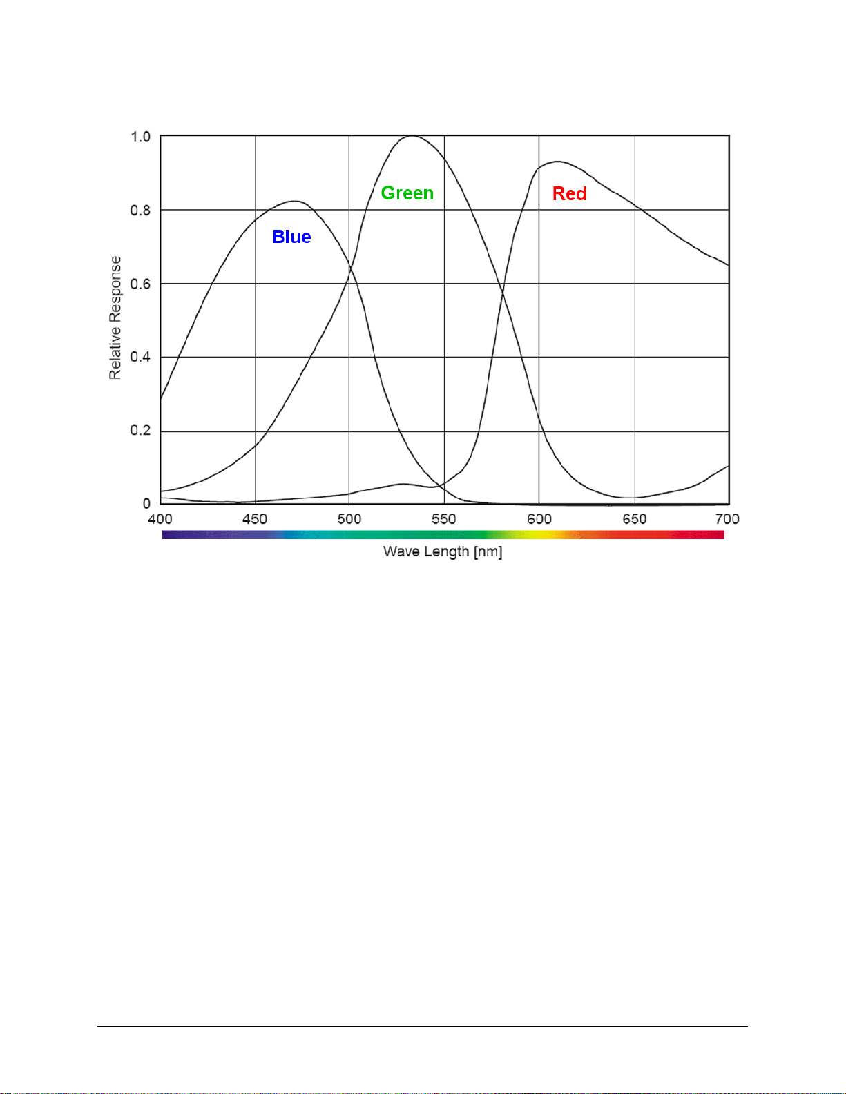
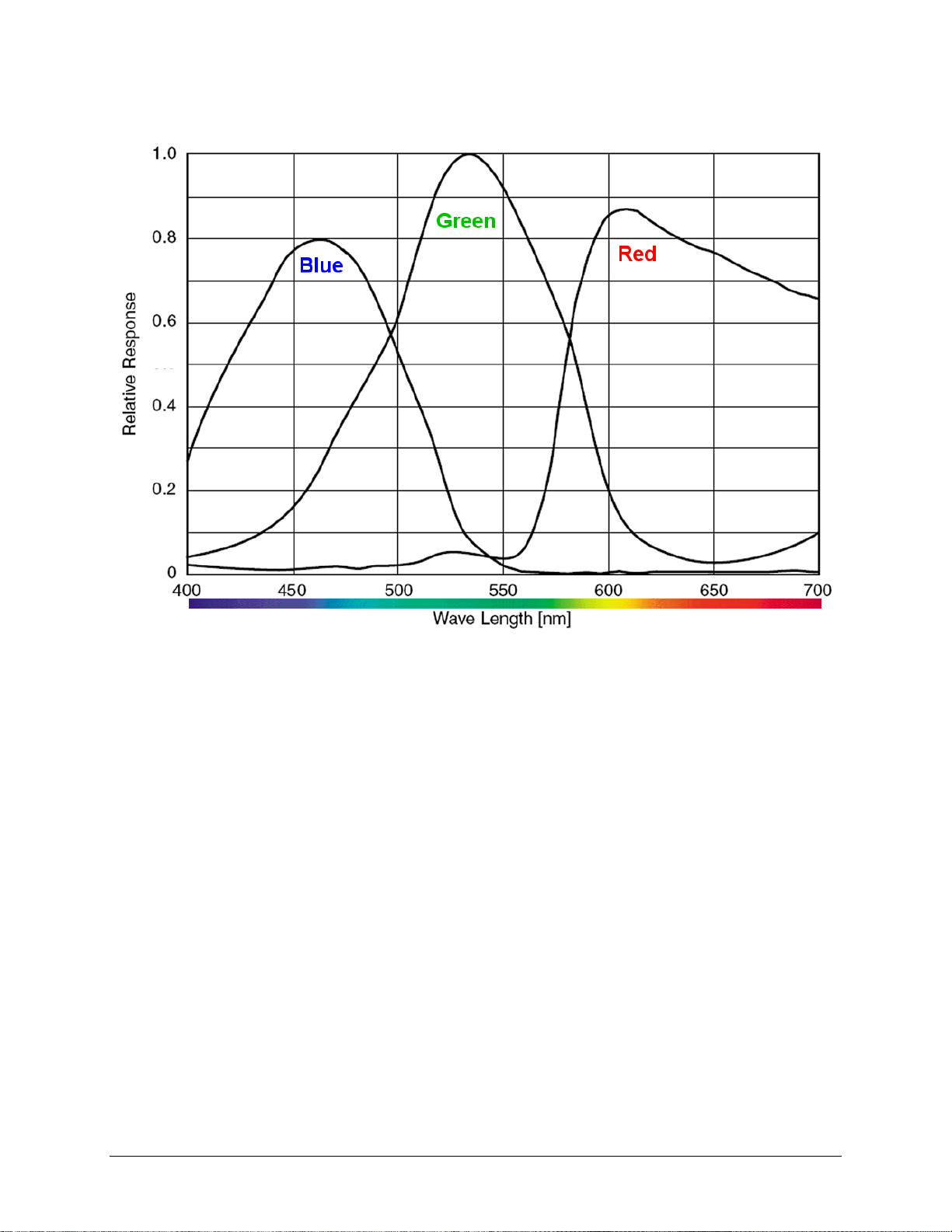
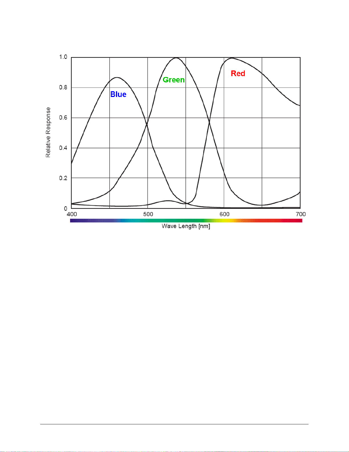
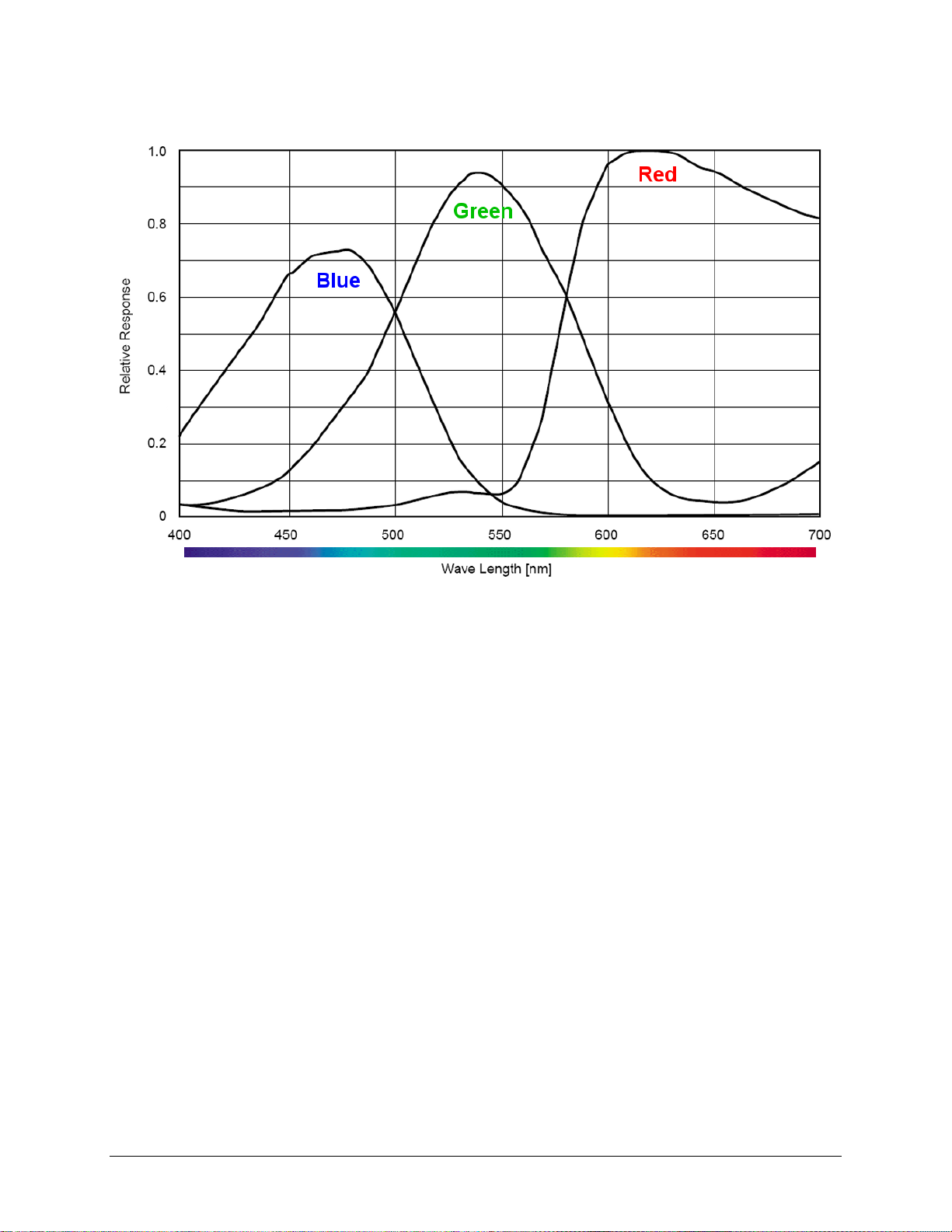
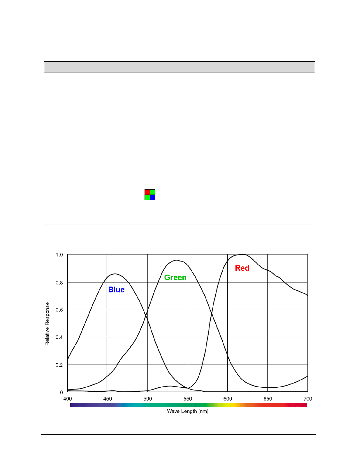
Each sensor description below provides a specification table and response graphic. The
graph describes the sensor RGB response to different wavelengths of light (excluding lens
and light source characteristics). Visible light spans wave lengths between about 390 - 780
nanometers. Wavelengths below 390 nm are termed ultra-violet while those above 780 nm.
are termed infra-red. The peak response for green is around 530 nanometers typical for
each sensor model.
10 • Genie Color Series Overview Genie Color Series-GigE Vision Camera

Bayer Decoding Algorithm is Sa pBayer::Method1 as
Genie C640-1/2 Specifications
Item / Feature Specification
Imager Format Full frame interline CCD area scan with square pixel (1/2 inch
diagonal)
Sensor Sony ICX414AQ
Resolution 640 x 480 pixels
Minimum Frame Rate (free-
running)
Maximum Frame Rate (free-
running)
Minimum Exposure 22μs
Maximum Exposure 16 seconds (note: maximum exposures are susceptible to hot-
Internal Trigge r to Start of
Exposure
Horizontal Line Tim e 32μs
Pixel Size 9.9µm x 9. 9µ m
Pixel Format 3x8-bit (RGB primary color m os aic filters on chip)
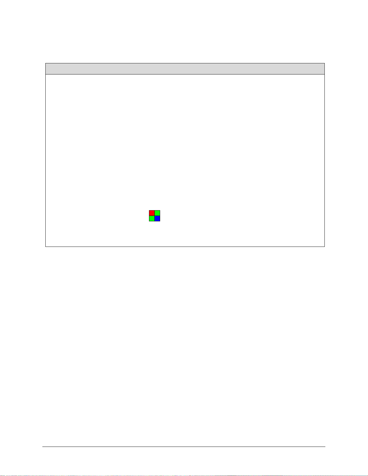
Bayer Mosaic Arrangement
Shutter Full frame electronic shutter
Gain Range -6dB to +12dB
0.1 fps (one frame ever y 10 seconds)
64 fps
pixel noise)
3.8μs
described
in the Sapera++ user manual.
Genie Color Series-GigE Vision Camera Genie Color Series Overview • 11
Genie C640-1/2 Responsivity
12 • Genie Color Series Overview Genie Color Series-GigE Vision Camera

Bayer Decoding Algorithm is Sa pBayer::Method1 as
Genie C640-1/3 Specifications
Item / Feature Specification
Imager Format Full frame interline CCD area scan with square pixel (1/3 inch
diagonal)
Sensor Sony ICX424AQ
Resolution 640 x 480 pixels
Minimum Frame Rate (free-
running)
Maximum Frame Rate (free-
running)
Minimum Exposure 22μs
Maximum Exposure 16 seconds (note: maximum exposures are susceptible to hot-
Internal Trigge r to Start of
Exposure
Horizontal Line Time 32μs
Pixel Size 7.4µm x 7. 4µ m
Pixel Format 3x8-bit (RGB primary color m os aic filters on chip)
Bayer Mosaic Arrangement
Shutter Full frame electronic shutter
Gain Range -6dB to +12dB
0.1 fps (one frame ever y 10 seconds)
64 fps
pixel noise)
3.8μs
described
in the Sapera++ user manual.
Genie Color Series-GigE Vision Camera Genie Color Series Overview • 13
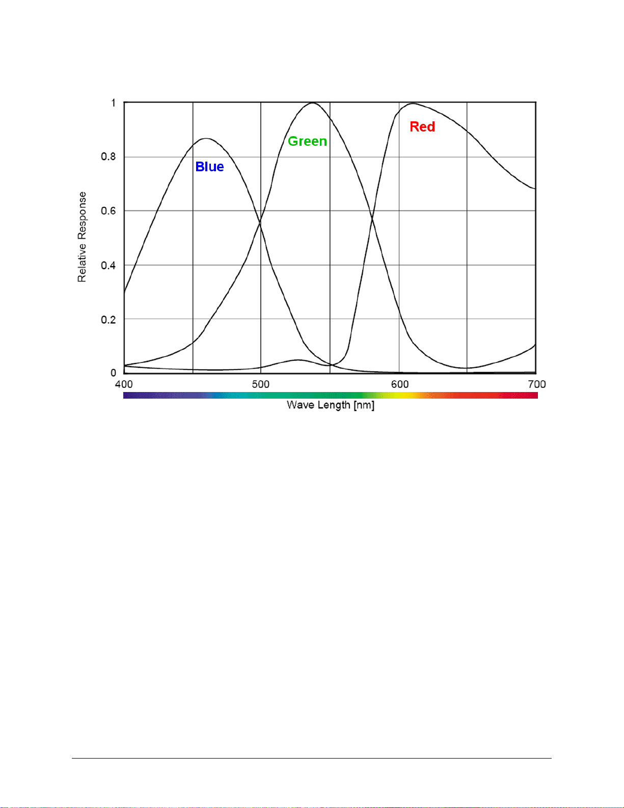
Genie C640-1/3 Responsivity
14 • Genie Color Series Overview Genie Color Series-GigE Vision Camera

Genie C1024-1/3 Specifications
Item / Feature Specification
Imager Format Full frame interline CCD area scan with square pixel (1/3 inch
diagonal)
Sensor Sony ICX204AK
Resolution 1024 x 768 pixels
Minimum Frame Rate (free-
running)
Maximum Frame Rate (free-
running)
Minimum Exposure 44μs
Maximum Exposure 16 seconds (note: maximum exposures are susceptible to hot-
Internal Trigge r to Start of
Exposure
Horizontal Line Tim e 63.5μs
Pixel Size 4.65μm (H) × 4.65μm (V)
Pixel Format 3x8-bit (RGB primary color m os aic filters on chip)
Bayer Mosaic Arrangement
Shutter Full frame electronic shutter
Gain Range -6dB to +12dB
0.1 fps (one frame ever y 10 seconds)
20 fps
pixel noise)
7.65μs
Bayer Decoding Algorithm is Sa pBayer::Method1 as
described
in the Sapera++ user manual.
Genie Color Series-GigE Vision Camera Genie Color Series Overview • 15
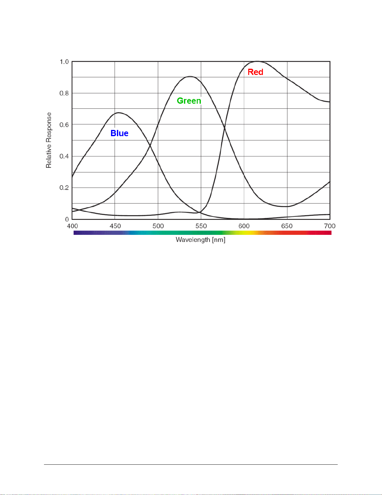
Genie C1024-1/3 Responsivity
16 • Genie Color Series Overview Genie Color Series-GigE Vision Camera

Genie C1280-1/3 Specifications
Item / Feature Specification
Imager Format Full frame interline CCD area scan with square pixel (1/3 inch
diagonal)
Sensor Sony ICX445AQA
Resolution 1280 x 960 pixels
Minimum Frame Rate (free-
running)
Maximum Frame Rate (free-
running)
Minimum Exposure 13μs
Maximum Exposure 16 seconds (note: maximum exposures are susceptible to hot-
Internal Trigge r to Start of
Exposure
Horizontal Line Tim e 42μs
Pixel Size 3.75μm (H) × 3.75μm (V)
Pixel Format 3x8-bit (RGB primary color m os aic filters on chip)
Bayer Mosaic Arrangement
Shutter Full frame electronic shutter
Gain Range -6dB to +12dB
0.1 fps (one frame ever y 10 seconds)
24.36 fps
pixel noise)
2.33μs
Bayer Decoding Algorithm is Sa pBayer::Method1 as
described
in the Sapera++ user manual.
Genie Color Series-GigE Vision Camera Genie Color Series Overview • 17
Genie C1280-1/3 Responsivity
18 • Genie Color Series Overview Genie Color Series-GigE Vision Camera
Bayer Decoding Algorithm is Sa pBayer::Method1 as
Genie C1400-1/2 Specifications
Item / Feature Specification
Imager Format Full frame interline CCD area scan with square pixel (1/2 inch
diagonal)
Sensor ICX267AK
Resolution 1360 x 1024 pixels
Minimum Frame Rate (free-
running)
Maximum Frame Rate (free-
running)
Minimum Exposure 32μs
Maximum Exposure 16 seconds (note: maximum exposures are susceptible to hot-
Internal Trigge r to Start of
Exposure
Horizontal Line Tim e 59.7μs
Pixel Size 4.65µm (H ) x 4.65µm (V)
Pixel Format 3x8-bit (RGB primary color m os aic filters on chip)
Bayer Mosaic Arrangement
Shutter Full frame electronic shutter
Gain Range -6dB to +12dB
0.1 fps (one frame ever y 10 seconds)
15 fps
pixel noise)
11.67μs
described
in the Sapera++ user manual.
Genie Color Series-GigE Vision Camera Genie Color Series Overview • 19
Genie C1400-1/2 Responsivity
20 • Genie Color Series Overview Genie Color Series-GigE Vision Camera

Genie C1410-2/3 Specifications
Item / Feature Specification
Imager Format Full frame interline CCD area scan with square pixel (2/3 inch
diagonal)
Sensor ICX285AQ
Resolution 1360 x 1024 pixels
Minimum Frame Rate (free-
running)
Maximum Frame Rate (free-
running)
Minimum Exposure 32μs
Maximum Exposure 16 seconds (note: maximum exposures are susceptible to hot-
Internal Trigge r to Start of
Exposure
Horizontal Line Tim e 44.2μs
Pixel Size 6.45µm (H ) x 6.45µm (V)
Pixel Format 3x8-bit (RGB primary color m os aic filters on chip)
Bayer Mosaic Arrangement
Shutter Full frame electronic shutter
Gain Range -6dB to +12dB
0.1 fps (one frame ever y 10 seconds)
21.9 fps
pixel noise)
4.15μs
Bayer Decoding Algorithm is Sa pBayer::Method1 as
described
in the Sapera++ user manual.
Genie Color Series-GigE Vision Camera Genie Color Series Overview • 21
Genie C1410-2/3 Responsivity
22 • Genie Color Series Overview Genie Color Series-GigE Vision Camera
Bayer Decoding Algorithm is Sa pBayer::Method1 as
Genie C1600-1/1.8 Specifications
Item / Feature Specification
Imager Format Full frame interline CCD area scan with square pixel (1/1.8
inch diagonal)
Sensor ICX274AQ
Resolution 1600 x 1200 pixels
Minimum Frame Rate (free-
running)
Maximum Frame Rate (free-
running)
Minimum Exposure 35μs
Maximum Exposure 16 seconds (note: maximum exposures are susceptible to hot-
Horizontal Line Tim e 53.3μs
Pixel Size 4.40µm (H ) x 4.40µm (V)
Pixel Format 3x8-bit (RGB primary color m os aic filters on chip)
Bayer Mosaic Arrangement
Shutter Full frame electronic shutter
Gain Range -6dB to +12dB
0.1 fps (one frame ever y 10 seconds)
15 fps
pixel noise)
described
in the Sapera++ user manual.
Genie C1600-1/1.8 Responsivity
Genie Color Series-GigE Vision Camera Genie Color Series Overview • 23
Application Development Overview
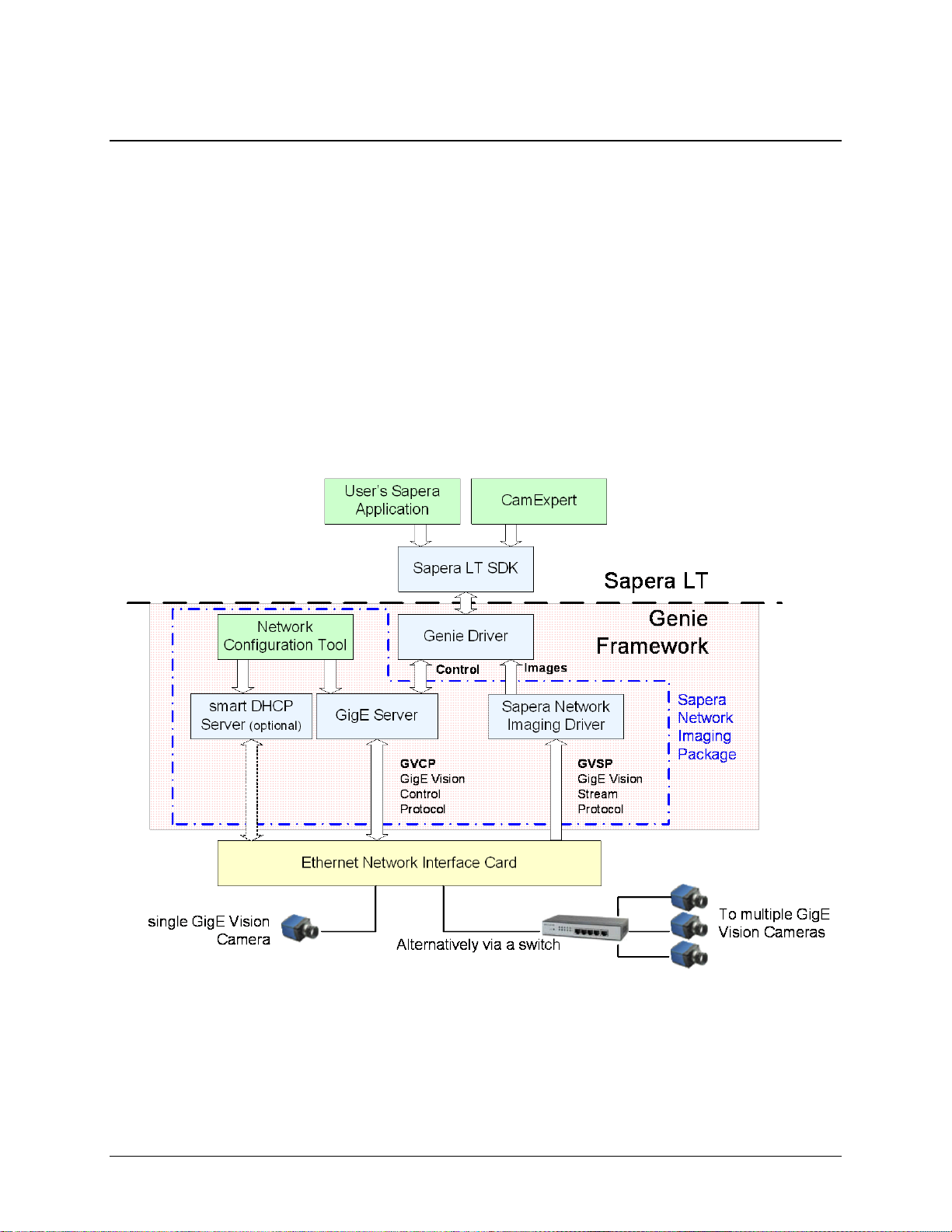
Sapera LT Library with optional Processing
Sapera LT is a powerful development library for image acquisition and control. Sapera LT
provides a single API across current and future Teledyne DALSA hardware. Sapera LT
delivers a comprehensive feature set including program portability, versatile camera
controls, flexible display functionality and management, plus eas y to use application
development wizards.
Sapera Processing is a comprehensive set of C++ classes for image processing and analysis.
Sapera Processing offers highly optimized tools for image processing, blob analysis, search
(pattern recognition), OCR and barcode decoding.
The following is a Sapera application functional block diagram. The Genie Framework
installation includes the Genie driver and the Sapera Network Imaging Package.
GigE Vision Compliant Environment
The GigE Visio n XML device description file is embedded w ithin Genie firmware allowing
GigE Vision compliant applicatio ns to know Genie capabilities im mediately after connection.
24 • Genie Color Series Overview Genie Color Series-GigE Vision Camera

Installing the Genie Camera
Warning! (Grounding Instructions)
Static electricity can damage electronic components. Please discharge any static electrical
charge by touching a grounded surface, such as the metal computer chassis, before
performing any hardware installation.
If you do not feel comfortable performing the installation, please consult a qualified
technician.
GigE Network Adapter Guideline
If the computer to be used with the Genie camera does not have a Gigabit network adapter
or second built in Gigabit NIC, a PCI bus Gigabit Network Interface Card (NIC) needs to be
installed. Typically under Windows, the PCI Gigabit NIC is recognized automatically when
Windows boots. An example of a high performance NIC is the Intel PRO/1000 MT adapter .
Review the NIC documentation concerning any special driver required for Windows. Install
the PCI bus Gigabit NIC as described by the NIC manufacture's documentation.
The Genie camera has been tested with a variety of Gigabit network adapters, both built
into the system motherboard and as third party PCI adapters.
Supported Network Configurations
The Genie obtains an IP address using the Link Local Address (LLA) or DHCP, by default. A
LLA IP address is obtained in about 6 seconds with Microsof t V ista/7 or in about 1 minute
with Microsoft XP. If required, a persistent IP address can be assigned (see "Running the
Network Configuration Tool" on page 33).
The LLA method automatically assigns the Genie with a randomly chosen address on the
169.254.xxx.xxx subnet. After an address is chosen, the link-local process sends an ARP
query with that IP onto the network to see if it is already in use. If there is no response, the
IP is assigned to the device, otherwise another IP is selected, and the ARP is repeated. Note
that LLA is unable to forward packets across routers.
Alternatively, if a DHCP server is present on the network, the Genie is going to issue a DHCP
request asking for an IP address. The DHCP server will then provide the Genie an IP
address. The Teledyne DALSA Network Configuration tool, installed with the Teledyne
DALSA Network Imaging Package, can also function as the DHCP server (refer to the
Teledyne DALSA Network Imaging Package user's manual).
Genie Color Series-GigE Vision Camera Installing the Genie Camera • 25
Installation Overview & Preparations
The Genie camera installation generally follows the sequence described below. Detailed
installation instructions follow this overview. This section also provides impo rtant
information to prevent operational faults due to ESD (electrostatic discharge) in Genie
installations.
Network and Computer Overview
• Genie needs to connect to a computer with a GigE network adapter, either built in on
the computer motherboard or installed as a third party PCI adapter.
• Laptop computers with built in GigE network adapters may still not be able to
stream full frame rates from Genie, especially when on battery power. Thorough testing
is required with any laptop computer to determine the maximum frame rate possible
(refer to the Teledyne DALSA Network Imaging Package user's manual).
• Genie also can connect through a Gigabit Ethernet switch. When using VLAN groups,
the Genie and controlling computer must be in the same group (refer to the Teledyne
DALSA Network Imaging Package user's manual)).
• If Genie is to be used in a Sapera development environment, Sapera LT needs to be
installed, either before or after the Genie software package. If Genie will be used in a
GigE Vision compliant environment, Sapera or Sapera runtime is not required and you
need to follow the installation instructions of the third party GigE Vision compliant
package.
• Install the Genie Framework software package if not using a third party GigE Vision
compliant package. Also install Sapera Run-time with CamExpert to control the
Genie.
• The Windows Firewall exceptions feature is automatically configured to allow the
Sapera GigE Server to pass through the firewall.
• Computers with VPN software (virtual private network) may need to have the VPN
driver disabled in the NIC properties. This would be required only on the NIC used with
the Genie. Testing by the user is required.
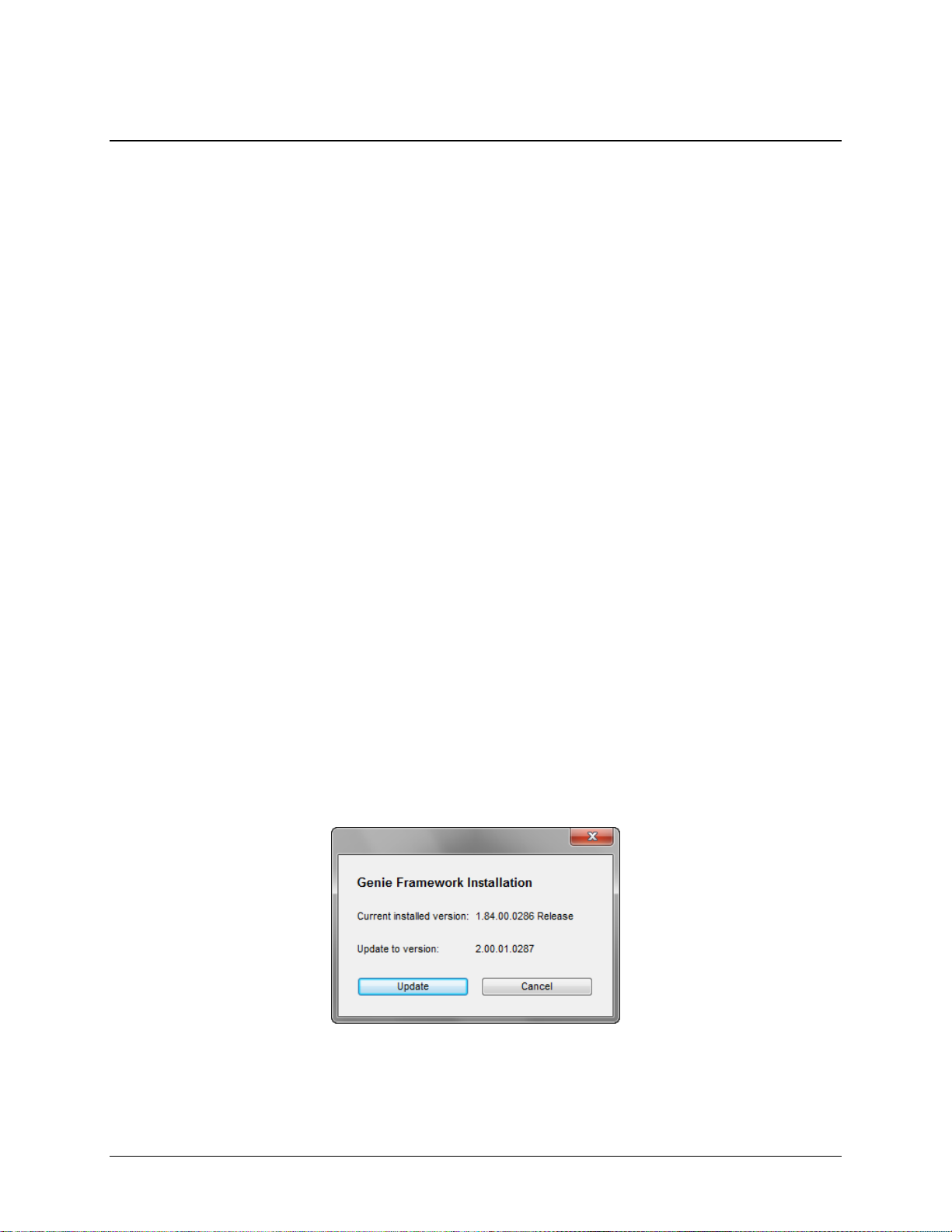
• When upgrading the Genie Framework from a previous version, there is no need to
uninstall the older version. The ne w installation will correctly update all framework files.
The framework installer will prompt you to confirm the upgrade, as shown.
26 • Installing the Genie Camera Genie Color Series-GigE Vision Camera

Installation Overview
• Before connecting power to the camera, test all power supplies. Power supplies must
meet the requirements defined in section "Genie Signal Electrical Details" on page 117.
Apply power to the camera.
• Connect Genie to the computer GigE network adapter or to the Ethernet switch via a
CAT5e or CAT6 Ethernet cable. Note: cable should not be less than 1 meter (3 feet) long
or more than 100 meters (328 feet) long.
• Check the diagnostic LED which will be initially red then switch to flas hing blue while
waiting for IP configuration. See "Status LED Codes" on page 31 for Genie LED display
descriptions.
• Look at the small camera ico n a dded to the Windows tray (next to the clock). Ensure the
Genie camera has been found (right click the icon and select Status).
• A new Genie installation typically requires a firmware update. See the procedure
"Updating Genie Firmware" on page 34.
• Use CamExpert (installed either with Sape ra or Sapera runtime) to te st the installation
of the Genie camera. Set the Genie to internal test pattern. See "Sapera CamExpert
Guide" on page 107.
• Set up the other components of the imaging system such as light sources, camera
mounts, optics, encoders, trigger sources, etc. Test with CamExpert.
Preventing Operational Faults due to ESD
Genie camera installations which do not protec t against ESD (electrostatic discharge) m a y
exhibit operational faults. Problems such as random packet loss, random camera resets, and
random loss of Ethernet connections, may all be solved by proper ESD management.
The Genie camera when used with a simple power supply and Ethernet cab le, is not properly
connected to earth ground and therefore is susceptible to ESD caused problems. An Ethernet
cable has no ground connection and a pow er supply's 0 volt return line is not necessarily
connected to earth ground.
Teledyne DALSA has performed ESD testing on Genie cameras using an 8 kilovolt ESD
generator without any indication of operational faults. The two following methods, either
individually or together will prevent ESD problems.
• Method 1: Use a shielded power supply cable where the shield is connected to earth
ground at the supply end and to the Hirose connector shell at the Genie end. The Genie
case is now properly connected to earth ground and can withstand ESD of 8 kilovolts, as
tested by Teledyne DALSA.
• Method 2: Mount the Genie camera on a metallic platform which has a g ood connection
to earth ground.
Genie Color Series-GigE Vision Camera Installing the Genie Camera • 27

Sapera LT Library Installation
Note: to install Sapera LT and the Genie device driver , logon to the workstation as an
administrator or w ith an account that has administrator privileges.
When Sapera application development is performed on the same computer that the Genie
Color is connected to, the Sapera Development Library (version 6.10 or later) must be
installed. Else, Sapera LT is not required to control the Genie camera.
• Insert the Teledyne DALSA Sapera CD-ROM. If AUTORUN is enabled on your computer,
the Teledyne DALSA installation menu is presented.
• If AUTORUN is not enabled, use Windows Explorer and browse to the root directory of
the CD-ROM. Execute launch.exe to start the Teledyne DALSA installation menu and
install the required Sapera components.
• The installation program will prompt you to reboot the computer.
• Continue with the Genie CD Package Installation described next.
Refer to Sapera LT User’s Manual concerning application development with Sapera.
Genie CD Package Installation
The Genie Framework software package and Sapera runtime provides all components
required to control the Genie with the supplied CamExpert tool. Genie Framework software
components include the Network Imaging driver (refer to the Teledyne DALSA Network
Imaging package manual), the Sapera GigE server, and CamExpert (if Sapera LT library is
not installed).
Note: If Sapera application development is requ ired, first install Sapera (6.10 or later) as
described in the previous section.
Procedure
• When upgrading the Genie Framework from a previous version, there is no need to
uninstall the older version. The ne w installation will correctly update all framework files.
• Insert the Teledyne DALSA Genie CD-ROM. If AUTORUN is enabled on your computer,
the Genie installation menu is presented.
• If AUTORUN is not enabled, use Windows Explorer and browse to the root directory of
the CD-ROM. Execute launch.exe to start the installation menu and install the Genie
software components.
• Click to install the Genie Framework Software which includes the Network Imaging
driver, and the Sapera GigE server.
• The procedure will prompt for acceptance of the installation folder for the Genie files.
• If Sapera LT is not installed and the Genie will be controlled with a Sapera application,
click to install Sapera LT run-time which includes CamExpert. Follow the on screen
prompts and reboot when the installation is complete.
28 • Installing the Genie Camera Genie Color Series-GigE Vision Camera
 Loading...