

Page 1

INSTRUCTION, OPERATING AND
MAINTENANCE MANUAL FOR
GC-PRO FID
P/N M82956
DATE 3/28/13
Toxic and/or flammable gases or liquids may be present in this monitoring system.
Personal protective equipment may be required when servicing this instrument.
Hazardous voltages exist on certain components internally which may persist for
a time even after the power is turned off and disconnected.
Only authorized personnel should conduct maintenance and/or servicing. Before
conducting any maintenance or servicing, consult with authorized
supervisor/manager.
Teledyne Analytical Instruments
DANGER
Page 2

GC-Pro FID
Copyright © 2013 Teledyne Analytical Instruments
All Rights Reserved. No part of this manual may be reproduced, transmitted, transcribed,
stored in a retrieval system, or translated into any other language or computer language in
whole or in part, in any form or by any means, whether it be electronic, mechanical,
magnetic, optical, manual, or otherwise, without the prior written consent of Teledyne
Analytical Instruments, 16830 Chestnut Street, City of Industry, CA 91748.
Warranty
This equipment is sold subject to the mutual agreement that it is warranted by us free from
defects of material and of construction, and that our liability shall be limited to replacing or
repairing at our factory (without charge, except for transportation), or at customer plant at
our option, any material or construction in which defects become apparent within one year
from the date of shipment, except in cases where quotations or acknowledgements provide
for a shorter period. Components manufactured by others bear the warranty of their
manufacturer. This warranty does not cover defects caused by wear, accident, misuse,
neglect or repairs other than those performed by Teledyne or an authorized service center.
We assume no liability for direct or indirect damages of any kind and the purchaser by the
acceptance of the equipment will assume all liability for any damage which may result from
its use or misuse.
We reserve the right to employ any suitable material in the manufacture of our apparatus,
and to make any alterations in the dimensions, shape or weight of any parts, in so far as
such alterations do not adversely affect our warranty.
Important Notice
This instrument provides measurement readings to its user, and serves as a tool by which
valuable data can be gathered. The information provided by the instrument may assist the user
in eliminating potential hazards caused by his process; however, it is essential that all
personnel involved in the use of the instrument or its interface be properly trained in the
process being measured, as well as all instrumentation related to it.
The safety of personnel is ultimately the responsibility of those who control process
conditions. While this instrument may be able to provide early warning of imminent
danger, it has no control over process conditions, and it can be misused. In particular, any
alarm or control systems installed must be tested and understood, both as to how they
operate and as to how they can be defeated. Any safeguards required such as locks, labels,
or redundancy, must be provided by the user or specifically requested of Teledyne at the
time the order is placed.
Therefore, the purchaser must be aware of the hazardous process conditions. The purchaser
is responsible for the training of personnel, for providing hazard warning methods and
instrumentation per the appropriate standards, and for ensuring that hazard warning devices
and instrumentation are maintained and operated properly.
Teledyne Analytical Instruments, the manufacturer of this instrument, cannot accept
responsibility for conditions beyond its knowledge and control. No statement expressed or
implied by this document or any information disseminated by the manufacturer or its
agents, is to be construed as a warranty of adequate safety control under the user’s process
conditions.
Teledyne Analytical Instruments ii
Page 3

GC-Pro FID
Safety Messages
Your safety and the safety of others are very important. We have
provided many important safety messages in this manual. Please read
these messages carefully.
A safety message alerts you to potential hazards that could hurt you
or others. Each safety message is associated with a safety alert symbol.
These symbols are found in the manual and inside the instrument. The
definition of these symbols is described below:
GENERAL WARNING/CAUTION: Refer to the
instructions for details on the specific danger. These
cautions warn of specific procedures which if not
followed could cause bodily Injury and/or damage the
instrument.
No
Symbol
CAUTION: HOT SURFACE WARNING: This warning is
specific to heated components within the instrument.
Failure to heed the warning could result in serious burns
to skin and underlying tissue.
WARNING: ELECTRICAL SHOCK HAZARD: Dangerous
voltages appear within this instrument. This warning is
specific to an electrical hazard existing at or nearby the
component or procedure under discussion. Failure to heed
this warning could result in injury and/or death from
electrocution.
Technician Symbol: All operations marked with this
symbol are to be performed by qualified maintenance
personnel only.
NOTE: Additional information and comments regarding
a specific component or procedure are highlighted in the
form of a note.
STAND-BY: This symbol indicates that the instrument is
on Stand-by but circuits are active.
Teledyne Analytical Instruments iii
Page 4

GC-Pro FID
CAUTION: THE ANALYZER SHOULD ONLY BE USED FOR THE
PURPOSE AND IN THE MANNER DESCRIBED IN
THIS MANUAL.
IF YOU USE THE ANALYZER IN A MANNER OTHER
THAN THAT FOR WHICH IT WAS INTENDED,
UNPREDICTABLE BEHAVIOR COULD RESULT
POSSIBLY ACCOMPANIED WITH HAZARDOUS
CONSEQUENCES.
This manual provides information designed to guide you through the
installation, calibration and operation of your new analyzer. Please read
this manual and keep it available.
Occasionally, some instruments are customized for a particular
application or features and/or options added per customer requests.
Please check the front of this manual for any additional information in
the form of an Addendum which discusses specific information,
procedures, cautions and warnings that may be specific to your
instrument.
Manuals do get misplaced. Additional manuals can be obtained from
Teledyne at the address given in the Appendix. Some of our manuals are
available in electronic form via the internet. Please visit our website at:
www.teledyne-ai.com.
Teledyne Analytical Instruments iv
Page 5

GC-Pro FID
Additional Safety Information
DANGER
COMBUSTIBLE GAS USAGE
This is a general purpose instrument designed for use in a
non-hazardous area. It is the customer's responsibility to
ensure safety especially when combustible gases are being
analyzed since the potential of gas leaks always exist.
WARNING
The customer should ensure that the principles of operating
of this equipment are well understood by the user. Misuse of
this product in any manner, tampering with its components,
or unauthorized substitution of any component may
adversely affect the safety of this instrument.
Since the use of this instrument is beyond the control of
Teledyne, no responsibility by Teledyne, its affiliates, and
agents for damage or injury from misuse or neglect of this
equipment is implied or assumed.
WARNING: HYDROGEN GAS IS USED IN THIS INSTRUMENT AS
A FUEL. HYDROGEN IS EXTREMELY FLAMMABLE.
EXTREME CARE MUST BE USED WHEN WORKING
AROUND GAS MIXTURES CONTAINING
FLAMMABLE GASES.
A successful leak check was performed at TAI on the
sample system of this instrument prior to calibration,
testing and shipping. Ensure that there are no leaks
in the fuel supply lines before applying power to the
system.
Teledyne Analytical Instruments v
Page 6

GC-Pro FID
Always purge the entire system before performing
any maintenance and always leak check the system
after removing any tubing or fittings on the sample
system. See the procedures for purging and leak
checking this instrument on the following pages.
If toxic gases or other hazardous materials are
introduced into the sample system, the same
precautions regarding leak checking and purging
apply to the sample lines and sample supply or
delivery lines.
WARNING: ELECTRICAL SHOCK HAZARD.
WITH THE EXCEPTION OF OPENING THE DOOR
AND ADJUSTING THE PRESSURE REGULATORS,
FLOW CONTROLLER, OR OBSERVING THE
PRESSURE GAUGES AND THE FLOWMETER, ONLY
AUTHORIZED AND SUITABLY TRAINED
PERSONNEL SHOULD PERFORM WORK INSIDE OF
THE INSTRUMENT. COMPONENTS WITHIN THE
COVER ON THE INSIDE OF THE DOOR, INSIDE THE
ISOTHERMAL CHAMBER (SAMPLE SYSTEM), AND
ON THE ELECTROMETER-AMPLIFIER PC BOARD
CONTAIN DANGEROUSLY HIGH VOLTAGE
SUFFICIENT TO CAUSE SERIOUS INJURY OR
DEATH.
There are the following three types of inaccessible
shock hazards within the Analyzer:
1. Line voltages and line related voltages such as
115 VAC which exists within the 230 VAC
versions as well. These voltages stop when the
Analyzer is turned off and the mains (line) cord is
removed from the instrument.
2. The sensor anode supply voltage (approximately
250 VDC). This voltage exists on the Flame
Guard, anode power supply, PCB, the
motherboard, and the anode/igniter terminals on
the sensor. THIS VOLTAGE WILL REMAIN
HAZARDOUS FOR MANY MINUTES AFTER THE
ANALYZER HAS BEEN TURNED OFF!
Teledyne Analytical Instruments vi
Page 7

GC-Pro FID
3. External hazardous voltages which may be
connected to the Analyzer alarm relay
connections.
Procedure for Removal of Internal Inaccessible
Shock Hazards
CAUTION: SERVICING OR MAINTENANCE OF THE ANALYZER
SHOULD ONLY BE DONE BY SUITABLE TRAINED
PERSONNEL. TO AVOID THESE INACCESSIBLE
1. Switch off the power to the Analyzer and remove the main (line)
power cord from the Analyzer.
HAZARDOUS VOLTAGES WHEN SERVICING THE
GC-PRO FID, PERFORM EACH OF THE FOLLOWING
STEPS, IN THE ORDER GIVEN, BEFORE SERVICING
BEGINS:
2. Remove all external voltages from the connections to the alarm
contacts.
3. Wait one minute.
4. Discharge the anode supply voltage.
a. Connect one end of an insulated (to 1000 VDC or more)
clip lead to Analyzer chassis ground (the standoff for the
upper right corner of the mother PCB).
b. Put one end of a 500V rated 1000 ohm resistor in the
other end of the clip lead.
c. Check the voltage between chassis ground (the standoff
for the upper right corner of the mother PCB) and the top
side of R2 at PCB number B74671. It should be between
-5VDC and +5VDC. If is in that range, the inaccessible
hazardous voltage removal procedure is completed, if not
repeat steps 4.a and 4.b.
If it is absolutely necessary to work inside the instrument with power
on, use the ONE HAND RULE:
Work with one hand only.
Keep the other hand free without contacting any other object. This
reduces the possibility of a ground path through the body in case of
accidental contact with hazardous voltages.
Teledyne Analytical Instruments vii
Page 8

GC-Pro FID
WARNING: THIS INSTRUMENT IS DESIGNED TO BE OPERATED
IN A NONHAZARDOUS AREA. THE ANALYZER USES
HYDROGEN GAS AND/OR OTHER COMBUSTIBLE
GASES IN ITS OPERATION. THIS EQUIPMENT, IF
NOT USED AND MAINTAINED PROPERLY CAN BE
AN EXPLOSION HAZARD. THE ANALYZER,
DEPENDING ON THE APPLICATION, MAY ALSO USE
TOXIC GASES. IT IS THEREFORE, THE
CUSTOMER'S RESPONSIBILITY TO ENSURE THAT
PROPER TRAINING AND UNDERSTANDING OF THE
PRINCIPLES OF OPERATION OF THIS EQUIPMENT
ARE UNDERSTOOD BY THE USER. SINCE THE USE
OF THIS INSTRUMENT IS BEYOND THE CONTROL
OF TELEDYNE, NO RESPONSIBILITY BY TELEDYNE,
ITS AFFILIATES AND AGENTS FOR DAMAGE OR
INJURY RESULTING FROM MISUSE OR NEGLECT
OF THIS INSTRUMENT IS IMPLIED OR ASSUMED.
MISUSE OF THIS PRODUCT IN ANY MANNER,
TAMPERING WITH ITS COMPONENTS OR
UNAUTHORIZED SUBSTITUTION OF ANY
COMPONENT MAY ADVERSELY AFFECT THE
SAFETY OF THIS INSTRUMENT.
CAUTION: WHEN OPERATING THIS INSTRUMENT, THE DOORS
MUST BE CLOSED AND ALL COVERS SECURELY
FASTENED. THE GAUGES MUST BE IN PROPER
WORKING ORDER. DO NOT OVERPRESSURIZE THE
SYSTEM.
READ THIS MANUAL BEFORE OPERATING THE
INSTRUMENT AND ADHERE TO ALL WARNINGS
INCLUDED IN THIS MANUAL.
Teledyne Analytical Instruments viii
Page 9

GC-Pro FID
Table of Contents
Safety Messages .......................................................................... iii
Additional Safety Information ...................................................... v
List of Figures ............................................................................. xiii
List of Tables .............................................................................. xiv
Introduction ................................................................................... 1
1.1 Main Features of the Analyzer 1
1.2 Principle of Operation 2
1.3 Analyzer Description 3
1.4 Applications 6
Operational Theory ....................................................................... 7
2.1 Introduction 7
2.2 Modes of Operation 8
2.3 Analyzer Subsystems 8
2.3.1 Sample System 9
2.3.2 Gas Flow Control System 9
2.3.3 Fuel and Blanket Air Systems 10
2.3.4 Flame Ionization Detection Cell 10
2.4 Detection Cell 12
2.4.1 Electrometer-Amplifier 13
2.4.2 Anode Power Supply 14
2.4.3 Flame Guard Circuit 14
2.4.4 Flame Ignition Circuit 14
Installation ................................................................................... 15
3.1 Unpacking the Analyzer 15
3.2 Mounting the Analyzer 15
Teledyne Analytical Instruments ix
Page 10

GC-Pro FID
3.3 User Connections 16
3.3.1 Electrical Power Connections 16
3.3.2 Electronic Connections 16
3.3.2.1 Primary Input Power 17
3.3.2.2 Fuse Installation 18
3.3.2.3 50-Pin Equipment Interface Connector 18
3.3.2.4 Analog Output 18
3.3.2.5 Alarm Relays 20
3.3.2.6 Digital Remote Cal Inputs 22
3.3.2.7 ‘Measure Once’ (or one shot measurement)
contacts 23
3.3.2.9 Pin Out Table 23
3.3.2.10 RS-232 Port 26
3.3.3 Gas Connections 27
3.3.3.1 Effluent 29
3.3.3.2 Sample Bypass Vent 29
3.3.3.3 Fuel and Air Connections 30
3.3.3.4 Sample and Span Gas Connections 30
3.4 Placing the System in Operation 30
Operation ..................................................................................... 31
4.1 Equipment 32
4.2 Preliminary Power-Off Check List 33
4.3 Powering Up the Unit 33
4.4 Activating the Support Gases 35
4.4.1 Air 35
4.4.2 Carrier Gas 36
4.4.3 Span Gas 36
4.4.4 Fuel 36
4.5 Sample Pump 36
4.6 Flame Ignition 36
Teledyne Analytical Instruments x
Page 11

GC-Pro FID
4.6.1 Verification of the Flame Guard Circuit 39
4.6.2 Ignition and/or Flame Guard Circuit Failure 40
4.7 Analyzer Operation 40
4.7.1 Default Parameters 41
4.7.2 The HOME Screen 41
4.7.3 The MENU Screen 43
4.7.4 Standby 44
4.7.5 Overlay Chromatogram 45
4.7.6 Timing 47
4.7.7 Temperature 51
4.7.7.1 Thermocouple 52
4.7.7.2 Settings 53
4.7.7.3 PID Settings 53
4.7.7.4 Status 55
4.7.8 Group Setup 55
4.7.9 Analog Adjust 59
4.7.10 Calibration 60
4.7.10.1 Span 61
4.7.10.2 Alt Span 63
4.7.10.3 Auto cal 66
4.7.11 Self Test 67
4.7.12 Settings 69
4.7.12.1 Alarms 70
4.7.12.2 Range 73
4.7.12.3 Change Stream 74
4.7.12.4 Time 75
4.7.12.5 Password 76
4.7.12.6 Communication 77
4.7.13 Analysis Mode 79
4.7.13.1 T-Time 80
Teledyne Analytical Instruments xi
Page 12

GC-Pro FID
4.7.13.2 T_Cycle 81
4.7.13.3 Chromatogram 82
4.7.13.4 VS Count 83
4.7.13.5 Cold Boot 83
Maintenance & Troubleshooting ................................................ 87
5.1 Measuring Circuit Electrical Checks 88
5.1.1 Anode Voltage Check 88
5.1.2 Electronic Stability 89
5.1.3 Printed Circuit Board Replacement 89
5.1.4 Collector Cable 90
5.2 Temperature Control Electronic Check 90
5.3 Ignition and/or Flame Guard Circuit Checks 91
5.4 Sampling System 92
5.5 Printed Circuit Board Descriptions 93
5.5.1 Flame Guard and Anode Power Supply PCB 93
5.5.2 Proportional Temperature Controller PCB 94
5.5.3 Electrometer-Amplifier PCB 95
Appendix ...................................................................................... 97
A.1 Specifications and Initial Settings: 97
A.2 Recommended Spare Parts List 98
A.3 Drawing List 99
Appendix B ................................................................................ 101
B1. VNC for GC-Pro FID 101
Appendix C ................................................................................ 107
C1 Addendum and Testing Results 107
Teledyne Analytical Instruments xii
Page 13

GC-Pro FID
List of Figures
Figure 1-1: GP-Pro Front Panel ....................................................... 3
Figure 1-2: GC-Pro FID Rear Panel ................................................ 4
Figure 1-3: Internal PCB Arrangement ............................................ 5
Figure 1-4: GC-Pro FID Internal View ............................................. 6
Figure 2-1: Internal Temperature Controller Screens ...................... 9
Figure 2-2: Typical Piping Diagram for the GC-Pro FID Analyzer . 11
Figure 2-4: Onscreen Re-Ignition Button ....................................... 14
Figure 3-1: GC-Pro FID Electronic Connections ............................ 17
Figure 3-2: Equipment Interface Connector Pin Arrangement ....... 18
Teledyne Analytical Instruments xiii
Page 14

GC-Pro FID
List of Tables
Table 3-1: Analog Output Connections — Middle Connector ........ 19
Table 3-2: Analog Concentration Output—Example ..................... 20
Table 3-4: Alarm Relay Contact Pins — Top Connector ............... 21
Table 3-5: Remote Calibration Connections — Bottom Connector 22
Table 3-6: ‘Measure Once’ Relay Connections ............................. 23
Table 3-7: Pin out of Alarm Relay O/P (Top) 50 pin D-Sub
Connector .................................................................... 24
Table 3-8: Pin out of Analog Signal (Middle) 50 pin D-Sub
Connector .................................................................... 24
Table 3-9: Pin out of Standard (Bottom) 50 pin D-Sub Connectors25
Table 3-10: Commands via RS-232 Input ..................................... 26
Table 3-11: Required RS-232 Options .......................................... 26
Teledyne Analytical Instruments xiv
Page 15

GC-Pro FID Introduction
Introduction
The GC-Pro FID Analyzer is a microprocessor controlled digital
instrument incorporating a Flame Ionization Detector (FID) coupled
with a gas separation column and switching valve designed to measure
the quantity of aromatic hydrocarbons present in a positive pressure
sample gas. Up to 8 channels of output are present for measuring
specific analytes in a sample stream. Unlike other benzene or
hydrocarbon analyzers, the GC-Pro FID Analyzer expands its diagnostic
capabilities to look for other aromatics, like toluene, ethyl benzene,
xylenes and other separable species. The GC-Pro FID Analyzer has
multiple channels for measurement with enhanced versatility and
capabilities. Due to its flexibility, it is vitally important that you refer to
Appendix C for the specific factory setup for your application.
The GC-Pro FID features a modern user interface with a touch
screen front panel facilitating operation, calibration, data collection and
display. With the Ethernet connectivity feature, this new interface allows
the instrument to be operated remotely with a VNC software application
from another digital device whereby the analyzer can be accessed,
controlled, data displayed etc. as if the analyzer were physically present.
Although the analyzer arrives already setup for your specific
application, a gas chromatograph mode allows the user to program the
instrument for measuring different species present in the sample.
1.1 Main Features of the Analyzer
The GC-Pro FID Analyzer is sophisticated yet simple to use. A
touch screen display on the front panel provides access all phases of
setup, calibration, operation, and troubleshooting on the GC-Pro FID.
The main features of the analyzer include:
Data acquisition and control functions supporting:
Pressure measurements, 5-Channels
Flow (MFC) measurements, 3-Channels
Oxygen measurements, 6-Channels
Teledyne Analytical Instruments 1
Page 16

Introduction GC-Pro FID
Temperature measurements and control, 4-Channels
6-Channel Dew point Hygrometer measurements, 6-
Channel
Relay, (10) and solenoid outputs, (4)
Alarm, (3) and over range indication outputs, (4)
4-20mA current loop outputs, 10 channels
HMI through Maple touch sensitive display
The system operates at single phase AC, 110 or 220V 50/60
Hz.
High resolution, accurate readings of concentration.
Versatile analysis with three user-definable analysis ranges.
Microprocessor based electronics: 8-bit CMOS
microprocessor with 32 kB RAM and 128 kB ROM.
Auto ranging allows analyzer to automatically select the
proper preset range for a given measurement. Manual
override allows the user to lock onto a specific range of
interest.
Two adjustable concentration alarms and a system failure
alarm.
Extensive self-diagnostic testing at startup and on demand
with continuous power supply monitoring.
RS-232 serial digital port for use with a computer or other
digital communication device.
8-Analog outputs for concentration and range identification
(0-1 VDC standard and isolated 4-20 mA dc).
Superior Accuracy
1.2 Principle of Operation
The analyzer uses a gas separation column to separate the
component of interest, for instance, benzene, from the other
hydrocarbons in the sample gas. Using a carrier gas and a
microprocessor actuated switching valve, the eluted gas is analyzed in
Teledyne Analytical Instruments 2
Page 17

GC-Pro FID Introduction
Flame Ionization Detector (FID) and the column is back flushed to
accept the fresh sample for the next cycle. More information is provided
in Section 2.1 Introduction, under Operational Theory. The electrical
output of the electrometer-amplifier is directly proportional to the
concentrations of the ionizable hydrocarbons present over the ranges of
interest.
1.3 Analyzer Description
The standard analyzer is a rack mountable instrument designed to fit
into a standard 19” instrument rack. The front interface screen is
mounted on the left side of the panel. The right side of the panel
includes the gas controls, pressure gauges and flowmeter. The front
panel is shown in Figure 1-1.
Figure 1-1: GP-Pro Front Panel
Gas pressure gauges and controls are mounted on the front panel
adjacent to the touch screen (human/machine interface abbreviated as
HMI) display as shown in Figure 1-1.
At the rear of the instrument are ports for the introduction of air,
fuel, zero, span, and sample gas as well as vent port connections. Three
50-pin user-interface cable connectors route input/output and alarm
signals to external devices. RS232 and a network port are also available
Teledyne Analytical Instruments 3
Page 18

Introduction GC-Pro FID
at the rear panel for connection to a remote computer or other digital
communication device. Internally, there are two USB user connections
which are used for updating firmware to the PCBs. Figure 1-2 shows the
rear panel including the user connections for the standard instrument
without the auto calibration manifold.
The analyzer is set up for either 120 VAC 60 Hz or 230 50/60 Hz
operation depending on the customer’s requirements. The appropriate
power cord for your unit is included with the analyzer.
Figure 1-2: GC-Pro FID Rear Panel
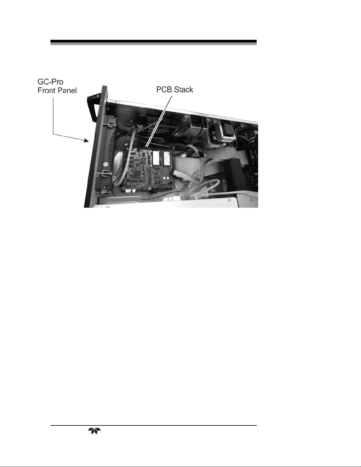
Internally, there are three isothermal chambers each separately
controlled for precise control and separation of analyzed species. In the
electronics section, internal PC boards are stacked in an assembly in an
order based on inter connectivity needs between the PCBs as well as
their association with other sub assemblies distributed within the system.
See Figure 1-3.
Following is the card stack-up from top to bottom planned inside the
system
Heater card
9261 controller card
Teledyne Analytical Instruments 4
Page 19

GC-Pro FID Introduction
Analog data acquisition card
Analog signal conditioning card
89C5131 controller card
Figure 1-3: Internal PCB Arrangement
Teledyne Analytical Instruments 5
Page 20
Introduction GC-Pro FID
Figure 1-4: GC-Pro FID Internal View
1.4 Applications
Monitoring the benzene concentration of carbon dioxide gas
for use in the beverage industry.
Monitoring aromatic contamination in air liquefaction and
other gas production processes.
Gas purity certification.
Detecting trace benzene in ambient air.
Detecting atmospheric pollutants.
Teledyne Analytical Instruments 6
Page 21

GC-Pro FID Operational Theory
Operational Theory
2.1 Introduction
The GC-Pro FID Analyzer uses a Flame Ionization Detector (FID)
and a Gas Chromatograph (GC) Column to separate and analyze
different factions of a volatile hydrocarbon sample. Using a carrier gas
and a microprocessor actuated switching valve, a fixed volume of
sample is pushed into the Column maintained at a constant temperature.
The eluted gas is analyzed for benzene or other specific analyate
configured for your specific application in a FID detector and the
column is back flushed to accept the fresh sample for the next cycle.
Actual separating and detecting sequence may vary depending on
compounds of interest in the application for which the analyzer is
configured.
The Flame Ionization Detector was selected for use in the GC-Pro
FID Analyzer based on the positive performance and extensive
experience in the use of this detector in other Teledyne analyzers. The
FID has proven itself to be a rugged, stable, long life sensor giving years
of trouble free operation in various applications. Also considering the
fact that the required sensitivity of 100 ppb full scale was achieved, FID
was considered a better choice over the limited life and less reliable
Photo Ionization Detector.
A stainless steel packed column containing Chromosorb Diatomite is
used at a constant temperature of 70°C. Using nitrogen as a carrier gas
and a 5 ml sample loop, benzene elutes from the column within a few
minutes. Additionally, a clear separation is observed from other
aromatic hydrocarbons, namely toluene, ethyl benzene, and xylenes. The
actual temperature setpoint and compound separation for your
instrument may be different depending on the application. It is listed in
the Addendum and Testing Results section of Appendix C.
Teledyne Analytical Instruments 7
Page 22

Operational Theory GC-Pro FID
2.2 Modes of Operation
The analyzer has 2 modes of operation depending on the position of
the GC Sampling Valve (See Piping Diagram in Figure 2-2). They are:
Sample Mode (position A) and Analysis Mode (position B).
1. Valve Position A—Sampling Mode
In this mode the analyzer configures the operational valve to
back flush the column and charge the sample loop. The Sample
Mode is programmed to continue for a 7 minute period by
factory default; however, it is usually modified to match the
needs of a particular process. The specific timing interval for
your system is listed in the Addendum and Testing Results
section of Appendix C. It is possible to set the Sample Mode
duration up to 25 minutes.
2. Valve Position B—Analysis Mode
In this mode the analyzer configures the sampling valve to feed
the gas in the sample loop through the column and to the
detector. The eluted sample from the column is fed to the FID
for the analysis of the compound of interest in the hydrocarbon
stream. If configured to do so, the analyzer may read the detector
for a programmed 5 second period at some point within this
mode cycle to obtain a baseline reading for further calculation.
This mode is usually programmed to continue until the
compound of interest is fully eluted from the column. It is
possible to set it up to 25 minutes.
During the Analysis Mode, a ‘Peak Detect’ period is programmed at
which time the analyzer reads the detector output. The analyzer
integrates the peak area during this time in conjunction with the baseline
settings to calculate the concentration of the compound of interest. The
calculation is performed at the end of the ‘Peak Detector’ period and the
result is displayed at the end of Analysis Mode.
2.3 Analyzer Subsystems
The Model Analyzer is composed of three subsystems:
1. Sample System
2. Detector Cell
3. Electronic Signal Processing, Display and Control
Teledyne Analytical Instruments 8
Page 23

GC-Pro FID Operational Theory
2.3.1 Sample System
All components used to control the sample and supporting gases, as
well as the combustion portion of the detector cell, are located inside the
analyzer chassis. They are accessible by opening the front door of the
analyzer.
Adjustments are made using the appropriate control on the front
panel.
The analyzer contains three separate isothermal chambers
‘SAMPLE’, ‘FID’, and ‘COLUMN’ that are controlled by internal
temperature control PCBs. The temperature can be monitored and
controlled using the touch screen main menu item ‘Temperature’. See
Figure 2-1 and Section 4.7.7.
Figure 2-1: Internal Temperature Controller Screens
The sample chamber contains the 10-port GC switching valve and 2
sample loops. The ‘FID’ chamber contains the flame, pressure
regulators, pressure gauges and flow restrictors used by the FID
detector. The ‘COLUMN’ is housed in a separate ‘COLUMN’ enclosure
and maintained at a temperature of 70° C by its PID temperature
controller. The actual temperature setpoint for your instrument may be
different depending on the application. It is listed in the Addendum and
Testing Results section of Appendix C.
2.3.2 Gas Flow Control System
The analyzer is equipped with ports for the introduction of air, fuel,
carrier gas, span, and sample gas. It is imperative that these gases are
supplied at constant pressures using two stage stainless steel diaphragm
gas regulators. The recommended pressure range is 30 to 80 psig;
however, the span gas should be supplied at a pressure of 20 psig to the
restrictor fitting either on the optional auto calibration module or the
span inlet on the rear panel.
Teledyne Analytical Instruments 9
Page 24

Operational Theory GC-Pro FID
The Piping Diagram for the standard instrument is shown in Figure
2-2. A 10-port 2-position GC sampling valve is used to control and
direct gas flows including sampling, back flush, and carrier gas. The
fixed volume sample loop ensures the same volume of sample injection
in the column every cycle.
If your instrument is fitted with the optional auto calibration module,
a separate compartment containing of a pair of solenoid valves is
installed for controlling the introduction of sample or span gas to the
detector. Calibration can be performed automatically on a programmed
schedule or manually using the front panel interface.
2.3.3 Fuel and Blanket Air Systems
Stable flow is achieved by maintaining a constant pressure across
restrictors upstream from the cell. Each system incorporates an adjustable
pressure regulator, pressure gauge, and restrictor. A flame out light is
included to indicate when the flame fails. A fuel shut-off solenoid valve,
mounted on the line that supplies fuel, stops the fuel flow in case of flame
failure. This valve is located in line with the fuel port.
2.3.4 Flame Ionization Detection Cell
The carrier gas containing sample and fuel are combined within a tee
fitting located in the isothermal chamber. The mixed gas is emitted from
a burner within the sensor assembly. Blanket air is introduced into the
sensor (or cell) by means of a separate fitting that is located in the base
section of the assembly. The upper half of the assembly houses the
anode-igniter, collector, and flame guard thermistor.
Teledyne Analytical Instruments 10
Page 25

GC-Pro FID Operational Theory
Figure 2-2: Typical Piping Diagram for the GC-Pro FID Analyzer
Teledyne Analytical Instruments 11
Page 26

Operational Theory GC-Pro FID
2.4 Detection Cell
The upper section of the stainless steel flame ionization cell houses
the cylindrical collector electrode, the high voltage (+260 VDC) anodeigniter coil, and the sensing thermistor of the flame guard circuit (see
cell cross-section in Figure 2-3).
WARNING: DANGEROUS HIGH VOLTAGE EXISTS AT THE
ANODE IGNITER COIL (+260 VDC). DO NOT
ATTEMPT TO DISCONNECT THE IGNITER COIL
CABLE OR DISASSEMBLE ANY OF THE FLAME
IONIZATION CELL COMPONENTS WITHOUT
TURNING OFF THE POWER AND DISCONNECTING
THE POWER CORD.
The collector is interconnected with the electrometer-amplifier PC
board by a coaxial cable. Although the cable and fittings are intended for
coaxial service, the cable is actually being used as a shielded singleconductor connection.
The anode-igniter, as its name implies, serves two functions. When
relay K2 at PCB part number B74671 is energized, the coil becomes an
electrical heating element that glows red-hot and ignites the hydrogen
fuel. When relay K2 at B74671 is de-energized, the coil is connected to
the +260 volt DC terminal of the anode-flame guard power supply PC
board. In this configuration, the necessary potential difference is
established between the coil (anode) and collector to promote ionization
of the burned hydrocarbons. The coil functions as the high voltage anode
in all three-range positions of the selector switch.
The thermistor acts as the sensor in the flame guard circuit. Its
ambient temperature resistance is in the 100 K ohms region. When the
flame is ignited, its resistance is reduced by a factor of 100. The
thermistor is coupled to a semiconductor control circuit on the anodeflame guard power supply PC board, which will be described in a
following section.
The cell electrodes of both the anode-igniter and flame guard
thermistor are connected to the electronics chassis by means of a plug-in
cable.
The electrode section of the cell may be removed for inspection by
turning off the power, disconnecting the electrode lead plug, and
removing the screws, which retain the electrode assembly in the sensor
body.
Teledyne Analytical Instruments 12
Page 27

GC-Pro FID Operational Theory
2.4.1 Electrometer-Amplifier
The collector cable is coupled directly to a coaxial fitting located on
the electrometer-amplifier PC board. The PC board is located on the side
panel next to but outside of the isothermal chamber. It consists of an
electrometer amplifier and an operational amplifier. This circuit is a very
high-gain, current-to-voltage converter circuit, having an input
impedance measuring in the billions of ohms. It is static sensitive and
highly susceptible to contamination. Special care must be taken in
handling this PC board.
Refer to Section 5.5.3: Electrometer-Amplifier PC Board for more
information concerning the electrometer-amplifier and the other printed
circuits that follow.
Figure 2-3: Flame Ionization Cell
Teledyne Analytical Instruments 13
Page 28

Operational Theory GC-Pro FID
2.4.2 Anode Power Supply
The high voltage anode power supply components are mounted on
the anode power supply printed circuit board. High voltage regulation is
achieved through the use of series-connected zener diodes. The
simplicity of this circuit’s design can be attributed to the extremely low
current demand of the anode circuit. The positive output voltage is
nominally 125 volts. Output tolerance is ±10 volts from the specified
125 volts.
2.4.3 Flame Guard Circuit
A thermistor-controlled, transistorized switching circuit is employed
to operate a relay in the event of a flame-out condition. A panel indicator
light and fuel shut-off solenoid valve are operated by the relay to alarm
personnel that a flame-out condition has occurred. The fuel shut-off
solenoid valve stops the hydrogen flow.
2.4.4 Flame Ignition Circuit
The flame ignition circuit includes the anode-igniter electrode (in the
detector cell), a transformer, and processor controlled relay. The circuit
is automatically energized when the FID cools due to lack of flame.
If automatic ignition fails five times, there will be a message that
reports this, and the flame can be re-ignited by pressing the re-ignite
icon from the touch screen. See Figure 2-4 and Section 4.6.
Figure 2-4: Onscreen Re-Ignition Button
Teledyne Analytical Instruments 14
Page 29

GC-Pro FID Installation
Installation
Installation of the GC-Pro FID Analyzer includes:
1. Unpacking
2. Mounting
3. Gas connections
4. Electrical connections
5. Testing the system.
3.1 Unpacking the Analyzer
Although the analyzer is shipped with all the materials you need to
install and prepare the system for operation. Carefully unpack the
Analyzer and inspect it for damage. Immediately report any damage or
shortages to the shipping agent.
3.2 Mounting the Analyzer
The GC-Pro FID is a general-purpose analyzer and is designed with
(non-sealed) enclosures. It must be installed in an area where the
ambient temperature is not permitted to drop below 32ºF or rise above
100ºF. In areas outside these temperatures, auxiliary heating/cooling
must be supplied. The GC-Pro FID enclosure is oil and dust resistant
and although it is designed to resist moisture, it should NOT be
considered completely watertight. Mounting to walls or racks must be
made securely. Avoid locations that are subject to extreme vibration and
sway.
Sufficient space must be provided around and above the analyzer to
accommodate the necessary electrical conduit and plumbing connections
and top cover removal. The top cover must be allowed to be lifted off for
possible service access to all components within the enclosure. Refer to
the system/analyzer outline drawings for dimensions.
Regardless of configuration, the analyzer/system must be installed
on a level surface with sufficient space allocated on either side for
Teledyne Analytical Instruments 15
Page 30

Installation GC-Pro FID
personnel and test equipment access. Subject to the foregoing, the
Analyzer/system should be placed as close to the sample point as is
possible.
All pertinent dimensions, connecting points, and piping details can
be found in the drawings section as part of the outline, input-output, and
piping diagrams. These drawings are specific to the instrument or
system to which the manual applies.
3.3 User Connections
All user connections are made on the rear panel. Consult the inputoutput and outline diagrams in the drawing section of the manual. Not
all the features displayed may be present in your system. Refer to any
Addenda for additional information that may apply to your instrument.
3.3.1 Electrical Power Connections
The standard analyzer requires a supply of 100-125VAC, singlephase power. Power connections are made at the rear panel of the unit.
Refer to the input-output diagram for more information. The electrical
power service must include a high-quality ground wire. A high-quality
ground wire is a wire that has zero potential difference when measured
to the power line neutral. If you have the 220 VAC option, you will
require 220 or 240 VAC, 50/60 Hz power. Check the analyzer inputoutput diagram, power schematic, outline, and wiring diagrams for
incoming power specifications and connecting points.
CAUTION: PRIMARY POWER TO THE SYSTEM SHOULD NOT
BE SUPPLIED UNTIL ALL CUSTOMERS WIRING IS
INSPECTED PROPERLY BY START-UP PERSONNEL.
3.3.2 Electronic Connections
Figure 3-1 shows the GC-Pro FID rear panel. There are connections
for power, digital communications, and both digital and analog
concentration output.
For safe connections, no uninsulated wiring should be able to come
in contact with fingers, tools or clothing during normal operation.
CAUTION: USE SHIELDED CABLES. ALSO, USE PLUGS THAT
PROVIDE EXCELLENT EMI/RFI PROTECTION. THE
PLUG CASE MUST BE CONNECTED TO THE CABLE
Teledyne Analytical Instruments 16
Page 31

GC-Pro FID Installation
SHIELD, AND IT MUST BE TIGHTLY FASTENED TO
THE ANALYZER WITH ITS FASTENING SCREWS.
ULTIMATELY, IT IS THE INSTALLER WHO ENSURES
THAT THE CONNECTIONS PROVIDE ADEQUATE
EMI/RFI SIELDING.
Figure 3-1: GC-Pro FID Electronic Connections
3.3.2.1
PRIMARY INPUT POWER
The power cord receptacle and fuse block are located in the same
assembly. Insert the power cord into the power cord receptacle.
CAUTION: POWER IS APPLIED TO THE INSTRUMENT'S
CIRCUITRY AS LONG AS THE INSTRUMENT IS
CONNECTED TO THE POWER SOURCE.
The standard power supply requires 110 VAC, 50/60 Hz or 220
VAC, 50/60 Hz (optional) power.
Teledyne Analytical Instruments 17
Page 32

Installation GC-Pro FID
3.3.2.2 FUSE INSTALLATION
The fuse block, at the right of the power cord receptacle, accepts US
or European size fuses. A jumper replaces the fuse in whichever fuse
receptacle is not used.
3.3.2.3 50-PIN EQUIPMENT INTERFACE CONNECTOR
There are three 50-pin Equipment Interface Connectors installed on
the rear panel of the GC-Pro FID. Figure 3-2 shows the pin layout of the
Equipment Interface connectors. The arrangement is shown as seen
when the viewer faces the rear panel of the analyzer. The pin numbers
for each input/output function are given where each function is
described in the paragraphs below.
Figure 3-2: Equipment Interface Connector Pin Arrangement
From top to bottom the signals handled by the individual connectors
are as follows:
Top connector: Alarm relay connections
Middle connector: Analog output signals
Bottom connector: Standard connector for all additional
signals
See Section 3.3.2.9 for Pin-Out connections for each connector.
3.3.2.4 ANALOG OUTPUT
There are four DC output signal pins—two pins per output. These
are found on the middle connector. For polarity, see Table 3-1. The
outputs are:
0–1 VDC % of Range: Voltage rises linearly with increasing
concentration, from 0 V at 0
concentration to 1 V at full scale. (Full
scale = 100% of programmable range.)
0–1 VDC Range ID: 0.20 V = Low Range
0.5 V = Medium Range
Teledyne Analytical Instruments 18
Page 33

GC-Pro FID Installation
0.80 V = High Range
4–20 mA DC % Range: Current increases linearly with
concentration, from 4 mA at 0
concentration to 20 mA at full scale.
(Full scale = 100% of programmable
range.)
4–20 mA dc Range ID: 6.8 mA = Range 1
12.0 mA = Range 2
16.8 mA = Range 3
Table 3-1: Analog Output Connections — Middle Connector
Pin Function
3 Channel 2, + 4-20 mA, floating
4 Channel 2, – 4-20 mA, floating
5 Channel 1, + 4-20 mA, floating
6 Channel 1, – 4-20 mA, floating
8 Channel 2, 0-1 VDC
23 Channel 2, 0-1 VDC, negative ground
24 Channel 1, 0-1 VDC
7 Channel 1, negative ground
Examples:
The analog output signal has a voltage which depends on gas
concentration relative to the full scale of the range. To relate the signal
output to the actual concentration, it is necessary to know what range the
instrument is currently on, especially when the analyzer is in the auto
ranging mode.
The signal output for concentration is linear over the currently
selected analysis range. For example, if the analyzer is set on a range
that was defined as 0-100 ppb benzene, then the output would be as
shown in Table 3-2.
Teledyne Analytical Instruments 19
Page 34

Installation GC-Pro FID
Table 3-2: Analog Concentration Output—Example
Ppb Voltage Signal Current Signal
Benzene Output (VDC) Output (mA DC)
0 0.0 4.0
10 0.1 5.6
20 0.2 7.2
30 0.3 8.8
40 0.4 10.4
50 0.5 12.0
60 0.6 13.6
70 0.7 15.2
80 0.8 16.8
90 0.9 18.4
100 1.0 20.0
3.3.2.5
ALARM RELAYS
The nine alarm-circuit connector pins connect to the internal alarm
relay contacts. The pins for the alarm relays are available from the top
interface connector. Each set of three pins provides one set of Form C
relay contacts. Each relay has both normally open and normally closed
contact connections. The contact connections are shown in Table 3-4.
They are capable of switching up to 3 amperes at 250 VAC into a
resistive load. The connectors are:
Threshold Alarm 1:
Can be configured as high (actuates when
concentration is above threshold), or low (actuates
when concentration is below threshold).
Can be configured as failsafe or non-failsafe
Can be configured as non-latching
Can be configured out (defeated).
Teledyne Analytical Instruments 20
Page 35

GC-Pro FID Installation
Threshold Alarm 2:
Can be configured as high (actuates when
concentration is above threshold), or low (actuates
when concentration is below threshold).
Can be configured as failsafe or non-failsafe
Can be configured as non-latching
Can be configured out (defeated).
System Alarm:
Actuates when DC power supplied to circuits is
unacceptable in one or more parameters. Permanently
configured as failsafe and latching. Cannot be
defeated.
Note: Reset by pressing the STANDBY button to remove power.
Then press STANDBY again and any other button except
SYSTEM to resume. Further detail can be found in
Chapter 4, Section 4.7.4.
Table 3-4: Alarm Relay Contact Pins — Top Connector
Pin Contact
45 Threshold Alarm 1, normally closed contact
28 Threshold Alarm 1, moving contact
46 Threshold Alarm 1, normally open contact
42 Threshold Alarm 2, normally closed contact
44 Threshold Alarm 2, moving contact
43 Threshold Alarm 2, normally open contact
36 System Alarm, normally closed contact
20 System Alarm, moving contact
37 System Alarm, normally open contact
Teledyne Analytical Instruments 21
Page 36

Installation GC-Pro FID
3.3.2.6 DIGITAL REMOTE CAL INPUTS
The digital remote calibration signals are available on the bottom
connector. They input accepts 0 V (off) or 24 VDC (on) for remote
control of calibration. (See Remote Calibration Protocol below.) See
Table 3-5 for pin connections.
Span: Floating input. A 5–24 V input across the + and – pins puts the
analyzer into the Span mode If cycle mode is ‘Continuous’. Either
side may be grounded at the source of the signal. A 0–1 volt across
the terminals allows Span mode to terminate when done. A
synchronous signal must open and close external span valve
appropriately.
Cal Contact: This relay contact is closed while analyzer is spanning.
(See Remote Calibration Protocol below.)
Table 3-5: Remote Calibration Connections — Bottom Connector
Pin Function
10 + Remote Span
12 – Remote Span
40 Cal Contact
41 Cal Contact
Remote Calibration Protocol: To properly time the Digital Remote Cal
Inputs to the GC-Pro FID Analyzer, the customer's controller must
monitor the Cal Relay Contact.
When the contact is OPEN, the analyzer is analyzing, the
Remote Cal Inputs are being polled, and a span command can be
sent.
When the contact is CLOSED, the analyzer is already calibrating. It
will ignore your request to calibrate, and it will not remember that
request.
Once a span command is sent, and acknowledged (contact closes),
release it. If the command is continued until after the span is complete,
the calibration will repeat and the Cal Relay Contact (CRC) will close
again.
For example:
Teledyne Analytical Instruments 22
Page 37

GC-Pro FID Installation
1. Test the CRC. When the CRC is open, send a span command
until the CRC closes (The CRC will quickly close.)
2. When the CRC closes, remove the span command.
When CRC opens again, the span calibration is done, and the sample
is being analyzed.
3.3.2.7 ‘MEASURE ONCE’ (OR ONE SHOT MEASUREMENT) CONTACTS
There are three dedicated relay contacts and these are available from
the bottom Equipment Interface Connector. They are assigned to
indicate status of ‘measure once’ (or one shot measurement). Contacts
are normally open, and they close when GC-Pro TCD switches to that
particular range.
Table 3-6: ‘Measure Once’ Relay Connections
Pin Function
9 + Start Measurement Digital Input
11 - Start Measurement Digital Input
21 IDLE Contact 1
38 IDLE Contact 2
22 IN MEASUREMENT Contact 1
39 IN MEASUREMENT Contact 2
19 MEASUREMENT DONE Contact 1
18 MEASUREMENT DONE Contact 2
MEASUREMENT DONE contact only closes for 5 seconds at end of
measurement cycle. After that IDLE contact closes. However reading is
display and analog output stays till new measurement is requested.
Digital input range is 5 to 24 vdc to start measurement.
3.3.2.9
PIN OUT TABLE
The following table summarizes all the outputs/inputs available on
the three 50 pin D-Sub connectors on the back panel of the analyzer.
Teledyne Analytical Instruments 23
Page 38

Installation GC-Pro FID
Table 3-7: Pin out of Alarm Relay O/P (Top) 50 pin D-Sub Connector
pin # Description
1 Alarm Relay # 9, NC contact
2 Alarm Relay # 9, C contact 27
3 Alarm Relay # 9, NO contact 28
4 Alarm Relay # 10, NC contact 29
5 Alarm Relay # 10, C contact 30
6 Alarm Relay # 10, NO contact 31
7 Alarm Relay # 11, NC contact 32
8 Alarm Relay # 11, C contact 33
9 Alarm Relay # 11, NO contact 34
10 Alarm Relay # 12, NC contact 35
11 Alarm Relay # 12, C contact 36
12 Alarm Relay # 12, NO contact 37
13 Alarm Relay # 13, NC contact 38
14 Alarm Relay # 13, C contact 39
15 Alarm Relay # 13, NO contact 40
16 Alarm Relay # 14, NC contact 41
17 Alarm Relay # 14, C contact 42
18 Alarm Relay # 14, NO contact 43
19 Alarm Relay # 15, NC contact 44
20 Alarm Relay # 15, C contact 45
21 Alarm Relay # 15, NO contact 46
22 Alarm Relay # 16, NC contact 47
23 Alarm Relay # 16, C contact 48
24 Alarm Relay # 16, NO contact 49
25 Alarm Relay # 17, NC contact 50
pin # Description
AlarmRelay#17,Ccontact
26
AlarmRelay#17,NOcontact
AlarmRelay#18,NCcontact
AlarmRelay#18,Ccontact
AlarmRelay#18,NOcontact
+15VDC
AnalogGround
+15VDC
AnalogGround
+15VDC
Ch.#1,4‐20madcinput,HOT
AnalogGround
+15VDC
Ch.#2,4‐20madcinput,HOT
AnalogGround
+15VDC
Ch.#3,4‐20madcinput,HOT
AnalogGround
+15VDC
Ch.#4,4‐20madcinput,HOT
AnalogGround
Ch.#5,4‐20madcinput,HOT
Ch.#6,4‐20madcinput,HOT
+15VDC
SpareAnalogInput
Table 3-8: Pin out of Analog Signal (Middle) 50 pin D-Sub Connector
pin # Description
1 4-20 ma Out, Ch. # 3- HOT
2 4-20 ma Out, Ch. # 3- RET 27 Analog Ground
3 4-20 ma Out, Ch. # 4- HOT 28 0-1 vdc Out, Ch. # 9 - HOT
4 4-20 ma Out, Ch. # 4- RET 29 0-1 vdc Out, Ch. # 10 - HOT
5 4-20 ma Out, Ch. # 5- HOT 30 Analog Ground
6 4-20 ma Out, Ch. # 5- RET 31 O2 sensor Hot Input #2 (NI)
7 4-20 ma Out, Ch. # 6- HOT 32 O2 sensor Return Input #2 (NI)
8 4-20 ma Out, Ch. # 6- RET 33 Thermistor for O2 sensor #2 ((NI)
9 4-20 ma Out, Ch. # 7- HOT 34 Thermistor for O2 sensor #2 (NI)
pin # Description
26 0-1 vdc Out, Ch. # 8 - HOT
Teledyne Analytical Instruments 24
Page 39

GC-Pro FID Installation
pin # Description
10 4-20 ma Out, Ch. # 7- RET 35 O2 sensor Hot Input #3 (NI)
11 4-20 ma Out, Ch. # 8- HOT 36 O2 sensor Return Input #3(NI)
12 4-20 ma Out, Ch. # 8- RET 37 Thermistor for O2 sensor #3 (NI)
13 4-20 ma Out, Ch. # 9- HOT 38 Thermistor for O2 sensor #3 (NI)
14 4-20 ma Out, Ch. # 9- RET 39 O2 sensor Hot Input #4 (NI)
15 4-20 ma Out, Ch. # 10- HOT 40 O2 sensor Return Input #4 (NI)
16 4-20 ma Out, Ch. # 10- RET 41 Thermistor for O2 sensor #4 (NI)
17 Analog Ground 42 Thermistor for O2 sensor #4 (NI)
18 Analog Ground 43 O2 sensor Hot Input #5 (NI)
19 0-1 vdc Out, Ch. # 3 - HOT 44 O2 sensor Return Input #5 (NI)
20 0-1 vdc Out, Ch. # 4 - HOT 45 Thermistor for O2 sensor #5 (NI)
21 Analog Ground 46 Thermistor for O2 sensor #5 (NI)
22 0-1 vdc Out, Ch. # 5 - HOT 47 O2 sensor Hot Input #6 (NI)
23 0-1 vdc Out, Ch. # 6 - HOT 48 O2 sensor Return Input #6 (NI)
24 Analog Ground 49 Thermistor for O2 sensor #6 (NI)
25 0-1 vdc Out, Ch. # 7 - HOT 50 Thermistor for O2 sensor #6 (NI)
pin # Description
(NI) = Not Implemented
Table 3-9: Pin out of Standard (Bottom) 50 pin D-Sub Connectors
pin # Description
1
2 27
3 + Output 4-20 ma - Channel 2 28 Alarm 1 C Contact
4 - Output 4-20 ma - Channel 2 29
5 + Output 4-20 ma – Channel 1 30
6 - Output 4-20 ma – Channel 1 31
7 - Output 0-1 v (Channel 1) 32 Exhaust Solenoid Hot
8 + Output 0-1 v (Channel 2) 33 Sample Solenoid Hot
9 34 Range 4 Contact/ not used
10 Remote Span + 35 Range 4 Contact/not used
11 36 Alarm 3 NC Contact
12 Remote Span - 37 Alarm 3 NO Contact
13 38 Range 1 Contact
14 39 Range 2 Contact
15 40 Calibration Contact
16 Span Solenoid Return 41 Calibration Contact
17 Span Solenoid Hot 42 Alarm 2 NC Contact
18 Range 3 Contact 43 Alarm 2 NO Contact
19 Range 3 Contact 44 Alarm 2 C Contact
20 Alarm 3 C Contact 45 Alarm 1 NC Contact
pin # Description
26
Teledyne Analytical Instruments 25
Page 40

Installation GC-Pro FID
pin # Description
21 Range 1 Contact 46 Alarm 1 NO Contact
22 Range 2 Contact 47
23 - Output 0-1 v (Channel 2) 48 Exhaust Solenoid Return
24 + Output 0-1 v (Channel 1) 49
25 50 Sample Solenoid Return
pin # Description
3.3.2.10 RS-232 PORT
The digital signal output is a standard RS-232 serial communications
port used to connect the analyzer to a computer, terminal, or other digital
device. It requires a standard 9-pin D connector.
Input: The input functions using RS-232 that have been implemented
to date are described in Table 3-8.
Table 3-10: Commands via RS-232 Input
Command Description
AS <enter> Auto Span immediately (continuous mode)
SV <enter> Switch to Span Valve
ZV <enter> Switch to Zero Valve
AV <enter> Switch to Analyze Valve
C1 <enter> If in 1Shot mode, start a cycle
C2 <enter> If in 1Shotm modde, start a span cycle
PMA <enter> Switch to standard message
PMB <enter> Switch to FID output mode
PMC <enter> Switch to Query Mode (used for interface with
OPC server)
Implementation: The RS-232 protocol allows some flexibility in its
implementation. Table 3-9 lists certain RS-232 values that are required
by the Standard Mode GC-Pro FID implementation.
Table 3-11: Required RS-232 Options
Baud 9600
Byte 8 bits
Parameter Setting
Teledyne Analytical Instruments 26
Page 41

GC-Pro FID Installation
Parity none
Stop Bits 1
Message Interval Sent at the end of each cycle.
3.3.3 Gas Connections
The analyzer gas connection diagram identifies the various gas
connection points as to function and location. Figure 3-1 shows the gas
connection points for the standard instrument without the optional auto
calibration module. If the optional auto calibration manifold is present,
sample and span gas connections would be made to labeled fittings on
the manifold.
Figure 3-3: Gas Connections
Note: For instruments without the auto calibration option, the
customer must provide means of switching sample and
span gas to the analyzer. It is recommended that you use
a tee with appropriate valves as opposed to disconnecting
the sample gas connection when span gas is required.
Gas connections to the instrument are made at the 1/8”or 1/4”
stainless steel tube fittings provided on the rear panel. Note that the
Teledyne Analytical Instruments 27
Page 42

Installation GC-Pro FID
optional purge (not shown) and sensor vent fittings are 1/4” while all
other gas connections are 1/8”.
It is recommended that all gas tubing leading to the connections on
the back of the analyzer be of the coiled type. This will facilitate sliding
the unit out of the case without disconnecting the gas supply to the
analyzer.
Before tubing is connected to the system, it must be decontaminated
to eliminate any hydrocarbon deposits. Using a small torch, heat each
length of tubing while passing nitrogen through it until it glows red.
Begin at the nitrogen source end and proceed down the length of the
tube, “chasing” the red glow (and hydrocarbon deposits) down to the
open end of the tube. Cap the tubing while not in use with suitable noncontaminating caps.
All sample, calibration, and supporting gas lines, which deliver gas
to the analyzer, must be decontaminated before connection; vent lines do
not.
When connecting the various gas lines to the system, be absolutely
certain that no “dead ends” are left; that is, no unused branch lines
should be left capped off, where pockets might form of material that is
not representative of the current contents of the line, or which might
keep contaminants from being purged out of the system.
CAUTION: THE GASES USED MUST BE OF THE HIGHEST
QUALITY, ULTRA ZERO GRADES, AS SHOWN
BELOW. FAILURE TO DO SO WILL RESULT IN
CONTAMINATION AND FAILURE TO DETECT AT
THE REQUIRED ACCURACY.
AIR: USE WATER PUMPED AIR WITH THC LESS THAN
0.1 PPM. DO NOT USE OIL PUMPED AIR UNDER
ANY CIRCUMSTANCES.
FUEL: HYDROGEN GAS, 100%, ZERO QUALITY WITH THC
LESS THAN 0.5 PPM.
CARRIER GAS: NITROGEN GAS, ULTRA ZERO GRADE WITH THC
LESS THAN 0.05 PPM.
Normally, four supporting gases of different composition (see
Section 4.1: Equipment) will be required to operate the analyzer. The
recommended composition is specified Appendix C: Addendum and
Testing Results. The gases should be supplied from cylinders that are
Teledyne Analytical Instruments 28
Page 43

GC-Pro FID Installation
equipped with the type of regulator specified in the aforementioned
sections.
CAUTION: UNDER NO CIRCUMSTANCES SHOULD YOU
EMPLOY A REGULATOR THAT IS NOT EQUIPPED
WITH A METALLIC DIAPHRAGM ANYWHERE IN THE
SYSTEM.
The regulators should be inspected prior to installation to be sure
that they are oil-free. Failure to comply with these directives will result
in a constant drift in analyzer output, as organic compounds will outgas
into the plumbing system at a rate that is related to the ambient
temperature. Use 316 stainless steel, dual-stage stainless steel diaphragm
regulators only in fuel, sample, and blanket air lines; shutoff valves
should be used downstream from each regulator.
Place the supply cylinders as close to the analyzer as possible, and
connect to the analyzer with new tubing. Be sure that all plumbing
connections are free of leaks.
Note: Use only stainless steel tubing throughout the system.
Consult the assembly, piping, outline drawings, and any
Addenda included with this manual to determine if special
conditions apply.
3.3.3.1 EFFLUENT
All the gases introduced into the detection cell vent from one fitting
at the rear of the analyzer. TAI recommends that the cell be permitted to
vent directly to the atmosphere wherever possible.
If a vent line is required, the installation must include a drop-out pot
to collect the water that is formed by the burning of the hydrogen fuel.
The vent line must be constructed so that water and dirt cannot collect in
it.
3.3.3.2 SAMPLE BYPASS VENT
The sample bypassed by the back-pressure regulation system vents
from a separate port at the rear of the analyzer. If a vent line is required,
it must be installed so that water and dirt cannot accumulate in it.
Teledyne Analytical Instruments 29
Page 44

Installation GC-Pro FID
3.3.3.3 FUEL AND AIR CONNECTIONS
The fuel used to provide combustion should be hydrogen gas, zero
quality with certified THC of less than 0.5 ppm and supplied at a
pressure of 40 psig. The compressed air, ultra zero gas quality with
THC less than 0.1 ppm should be used and supplied at a pressure of 40
psig. Connect the fuel and air sources to the instrument according to the
gas connection diagram included at the back of this manual.
3.3.3.4 SAMPLE AND SPAN GAS CONNECTIONS
The sample and span gas connections are made at the rear panel. If
the optional auto calibration module is installed, the sample and span gas
will connect to this module. If no auto calibration module is present,
these gases connect to the labeled fittings on the rear panel.
Set the supply pressure for sample and span gas to 20 psig.
3.4 Placing the System in Operation
See Section 4 for information on starting the analyzer for the first
time. Make sure that all electrical connections have been made correctly
and all connectors are fully seated. Make sure all gas connections are
correct and leak–free.
Teledyne Analytical Instruments 30
Page 45

GC-Pro FID Operation
Operation
This section of the manual describes how to setup and operate the
GC-Pro FID Analyzer. It includes preliminary steps and equipment
needed for operation, initial startup, and then the actual operation of the
analyzer using the touch screen interface is described. You should read
this chapter in its entirety and become familiar with the operating
characteristics of this system before starting the analyzer for the first
time. The Addendum and Testing Results section of Appendix C lists the
software revision and default settings for your specific analyzer.
The GC-Pro FID Analyzer incorporates a HMI interface that uses a
touch-sensitive LCD display with menus logistically grouped for easy,
intuitive access to all functions. The features supported by the newly
designed system HMI interface include:
1. Sensor data acquisition, data logging and system health
monitoring performed through the touch-screen display.
2. Firmware up-grades of the 89C5131 PCB can be carried out
through an internal USB 2.0 interface
3. Firmware up-grade for the 9261 controller board can be carried
out through the USB 2.0 interface using the SAMBA tool.
4. Stand alone testing of the 89C5131 PCB can be performed
through the debug hyper terminal (9600Kbps) connection on the
rear panel.
Operation of the analyzer including setup functions are performed
from the touch screen. The HOME screen is the main display screen and
the MENU screen allows the user to enter any phase of operation,
calibration, and setup simply by touching the specific on-screen button.
See Section 4.7.
Teledyne Analytical Instruments 31
Page 46

Operation GC-Pro FID
4.1 Equipment
The following supporting gases and hardware will be required to
operate the (standard) analyzer:
1. Fuel: A cylinder containing a hydrogen gas, zero gas quality
composition will be required to supply the fuel for the flame
ionization burner. The cylinder is to be equipped with an oil-free
metallic diaphragm regulator (dual stage).
2. Blanket Air: A cylinder of compressed air, zero gas quality will
be required to maintain the proper atmosphere within the cell.
The cylinder is to be equipped with an oil-free, dual stage,
metallic diaphragm regulator.
3. Carrier Gas: A cylinder of nitrogen gas, zero gas quality,
equipped with dual stage metallic diaphragm regulator is
required.
4. Span Gas: A cylinder or a permeation device system, capable of
generating known concentration of benzene and/or other
aromatic hydrocarbons of interest, will be required to standardize
the analyzer.
5. Sample Pressure Regulation: An oil-free, metallic diaphragm
regulator must be installed at the sample point when possible; see
Section 3.3.3 Gas Connections.
CAUTION: THE GASES USED MUST BE OF THE HIGHEST
QUALITY, ULTRA ZERO GRADES, AS SHOWN
BELOW. FAILURE TO DO SO WILL RESULT IN
CONTAMINATION AND FAILURE TO DETECT
THE REQUIRED ACCURACY.
AT
AIR: USE WATER PUMPED AIR WITH THC LESS
THAN 0.1 PPM. DO NOT USE OIL PUMPED AIR
UNDER ANY CIRCUMSTANCES.
FUEL: HYDROGEN GAS, 100%, ZERO QUALITY
WITH THC LESS THAN 0.5 PPM.
CARRIER GAS: NITROGEN GAS, ULTRA ZERO
GRADE WITH THC LESS THAN 0.05 PPM.
Teledyne Analytical Instruments 32
Page 47

GC-Pro FID Operation
4.2 Preliminary Power-Off Check List
Make the following checks of the installation before proceeding
further into the start-up procedure:
1. Check to see that the sample and supporting gas installation is in
accordance with the specifications called for in the installation
and application sections of the manual (Chapter 3). Be sure that
the supporting gases are of the proper composition and are
connected to the correct fittings at the rear of the analyzer.
2. Check to see that the electrical installation conforms to the
instructions contained in the installation section (Chapter 3) and
on the input-output diagram.
3. Remove the top cover and check to see that the printed circuit
boards and cables are firmly seated in their respective sockets.
4. Confirm that recorder and alarm connections are properly made.
4.3 Powering Up the Unit
Before applying power to the analyzer for the first time perform the
following checks:
1. Make sure that the proper power 120/220 VAC 50/60 Hz is
available.
2. Connect the AC power cord to the rear panel and then plug the
other end into the mains supply. As soon as power is established,
the unit will turn on.
3. Check that the Power, CPU, and COM LEDs illuminate and the
Teledyne Logo screen appears on the display.
Teledyne Analytical Instruments 33
Page 48

Operation GC-Pro FID
4. Momentarily, the Teledyne screen will be replaced with a second
start-up screen that lists the Model, Serial Number, Software
Version and other parameters specific to your instrument.
5. A one hour warm up time is required for the internal heaters to
come up to the required temperature and stabilize. The screen
will indicate a countdown as the warm up period progresses.
6. During the warm up period activate the support gases as
described in Section 4.4.
Teledyne Analytical Instruments 34
Page 49

GC-Pro FID Operation
7. Following the warm up, the system will initiate a self-diagnostic
routine and display the results as either “OK” or “Failed”
8. After the self diagnostic test has completed the instrument will
attempt to ignite the flame. See Section 4.6.
4.4 Activating the Support Gases
The instrument gas controls are located on the front panel adjacent to
the touch screen display as shown in Figure 1-1. Make sure that the
following support gases are available at the analyzer:
Air: (HC-free) for combustion
Carrier gas: (usually nitrogen but refer to Appendix C for
your specific application.
Fuel: 100% hydrogen
Span gas: Typically 70-90% of measured component on
the range of interest in a clean background gas.
Refer to Appendix C for the specific span gas
composition for your application.
4.4.1 Air
1. Set the air source regulator to 40 psig.
2. Adjust the analyzer air regulator until the air pressure gauge
reads the recommended air pressure of 7.0 psig.
Teledyne Analytical Instruments 35
Page 50

Operation GC-Pro FID
After the air is flowing through the sensor and warm-up time has
been completed, activate the following gases:
4.4.2 Carrier Gas
Set the carrier gas source regulator to 80 psig and adjust the analyzer
sample regulator until the sample pressure gauge reads the
recommended sample pressure of 7.0 psig.
4.4.3 Span Gas
1. Feed span gas to the analyzer (see Section 4.4.3). Gas switching
can be performed manually or handled through the auto
calibration valves (if the option is added). See Section 4.7.10.3.
2. Observe that the analyzer sample flow meter reads from 0.3 to
1.0 SCFH.
4.4.4 Fuel
1. Open the main valve on the fuel source and set the fuel pressure
regulator to 40 psig.
2. Adjust the fuel regulator until its pressure gauge reads the
recommended pressure of 4.0 psig.
Note: Adjust fuel settings only when the red LED (flame failure
light) is off.
4.5 Sample Pump
A built-in sample pump is provided to draw sample gas from
ambient air. The gas flow rate should be maintained at about 1000 to
1200 cc/minute using the Front Panel flow control valve (clockwise
increases flow). See Figure 1-1.
4.6 Flame Ignition
After the warm up countdown on the display reaches zero, open the
gas control door and observe that the amber heater lamp is blinking
(indicating that the temperature controller is maintaining the temperature
setpoint) and the red Flame Out lamp on the front panel is on. See
Figure 1-1.
Teledyne Analytical Instruments 36
Page 51

GC-Pro FID Operation
The GC-Pro FID will automatically attempt a flame ignition
sequence following the warm up period which has been preset at the
factory.
If the ignition process fails, the instrument will attempt to ignite the
flame 4 more times. If it continues to fail after the fifth attempt, a flame
failure message will appear on the display. If this occurs refer to Section
5.
Attempting to reignite the flame by touching the “RE-IGNITE”
button will display a confirmation window as shown below.
Teledyne Analytical Instruments 37
Page 52

Operation GC-Pro FID
Again the ignition process will start if user selects the “OK” button.
The number of attempts will be updated on the screen below.
The above process will repeat until the flame ignites successfully.
The status will be updated as shown in the next screen.
Once the ignition process is successful the HOME screen will appear
on the display.
Teledyne Analytical Instruments 38
Page 53

GC-Pro FID Operation
4.6.1 Verification of the Flame Guard Circuit
Prior to using the analyzer for the first time, the operation of the
flame guard circuit should be checked. This circuit has been checked at
the factory, but should be re-verified during start-up. Use the following
procedure after ignition of the flame has been achieved:
1. Turn off the fuel at the supply cylinder.
2. Observe the fuel pressure gauge on the analyzer control panel. The
gauge indication will decay as the fuel in the line is exhausted.
When the gauge reading reaches near zero, the flame will
extinguish as the fuel solenoid shuts off the fuel supply. The
display will indicate an ignition failure followed by a request to reignite.
3. The analyzer will automatically try to re-ignite. After 5 attempts, it
will display: flame failure, check air, fuel and the flame failure
LED will be on.
4. Open the cylinder supply valve and re-ignite the flame by
pressing the ‘OK’ button on the Re-ignite screen.
Teledyne Analytical Instruments 39
Page 54

Operation GC-Pro FID
4.6.2 Ignition and/or Flame Guard Circuit Failure
If the flame ignition or guard circuits do not operate as described in
the above two sections, set the instrument fuel regulator to the
recommended pressure. If still fails to ignite, proceed as directed in
Chapter 5: Maintenance & Troubleshooting.
4.7 Analyzer Operation
Although the GC-Pro FID has been programmed for your
application at the factory, it can be further configured at the operator
level. Depending on the specifics of the application, this might include
all or a set of the following procedures:
1. Setting system parameters
Establish a security password, if desired, requiring operator
to log in.
Establish and start an automatic calibration cycle (if equipped
with the optional auto calibration module).
2. Routine operation.
Calibrate the instrument.
Choose auto ranging or select a fixed range of analysis.
Set alarm setpoints and modes of alarm operation.
3. Special functions setup.
Calibrate analog output, select analog output source.
Procedures for accessing and/or changing parameters as well as
analyzer operation are detailed in the sections to follow. All functions
can be accessed from the MENU screen which is accessible via the
center button on the HOME screen.
The default screen is the HOME screen (see Section 4.7.2). This is
the analysis display and shows details regarding the current sample
being analyzed. However, the user can go directly to any function
supported by the analyzer by pressing the MENU button. The only
exception to this is when the instrument is powered up. It will go
through a warm-up period, followed by a diagnostic self-test routine as
explained in Section 4.3.
Teledyne Analytical Instruments 40
Page 55

GC-Pro FID Operation
4.7.1 Default Parameters
The versatility of this analyzer usually results in significant changes
being made to parameters over the course of time to better suit a
particular application. Occasionally processes change requiring
alteration to alarms, filter settings etc. At some time, it may be
beneficial to reset the analyzer to the default conditions as it was when
shipped from the factory. Below is a listing of the default parameters
used in configuring the typical GC-Pro FID instrument. Your specific
application may require different settings. Refer to the Addendum and
Testing Results section of Appendix C for any specific changes or
recommendations that apply to your application.
Range/Application: Refer to the Addendum and Testing
Results section of Appendix C
Range: Manual
Alarms: Defeated, 20ppb, 50ppb, HI, NON-
FAILSAFE, NON-LATCHING
Auto Span Timing: Defeated, every 7 days, at 12 hours
Span: 80 ppb
Password: 11111
4.7.2 The HOME Screen
The HOME screen is the default display and represents the Analysis
Mode of the instrument. It is a set of two screens that present
information regarding the current measurement state. The HOME screen
is where the maximum information about the instrument is displayed.
The Group name/tag is listed on the left most column and the
concentration for groups are displayed in PPB, PPM or % depending on
the range and value. The Enabled group is represented by the glowing
LED. Each group has three user settable ranges R1, R2, and R3 and the
current range index is displayed in the Group row. It is possible to view
the VS (Volt-second) count by touching the “Vs Count” button.
Teledyne Analytical Instruments 41
Page 56

Operation GC-Pro FID
The phase cycle (forward or reverse) and corresponding phase timer
along with the cell ADC value are displayed in the lower box. The green
LED within the rectangle starts blinking whenever a peak is detected for
active time frames (groups) running in the respective cycle.
The ten groups are split into two screens showing five on each
screen. Either screen can be displayed by selecting “NEXT” and
“PREV” on the HOME screen.
A “Cold Boot” button is located on the bottom left corner of the
HOME screen that when pressed will allow the user to revert back to
factory settings or retain the current instrument settings. See Section
4.7.13.5 for additional details regarding a cold boot.
Teledyne Analytical Instruments 42
Page 57

GC-Pro FID Operation
Each group has buttons associated with it (T_Time and T-Cycle) that
will bring up a graph displaying the analysis trend in the group with
respect to time or cycle. With these buttons, the user can evaluate the
instantaneous analysis as opposed to waiting for a complete cycle to
terminate. See Section 4.7.13 for more details.
4.7.3 The MENU Screen
Instrument parameters can be accessed and set by pressing the
“MENU” button on the HOME screen. This brings up the following
MENU screen:
Any function can be entered by touching the respective icon. The
functions are:
Standby (lower left corner on display)
Home (home icon at bottom center)
Overlay Chromatogram
Timing
Temperature
Group Setup
Analog Adjust
Calibration
Self Test
Teledyne Analytical Instruments 43
Page 58

Operation GC-Pro FID
Settings
Firmware Upgrade
These functions are described in the sections that follow.
4.7.4 Standby
This function allows you to place the instrument in STANDBY
mode.
CAUTION: STANDBY SHUTS DOWN POWER TO THE DISPLAYS
ONLY. INTERNAL CIRCUITS ARE STILL ENERGIZED
AND ELECTRICAL SHOCK HAZARD STILL EXISTS.
To place the instrument in STANDBY status press the “Standby” button
at the lower left corner of the display. The following Confirmation
screen will pop up.
Selecting ‘OK” puts the system goes into a sleep mode and
following window will be displayed on the screen.
Teledyne Analytical Instruments 44
Page 59

GC-Pro FID Operation
To come out of standby mode, touch the “WAKE UP” button. An
informational pop up screen will appear for approximately one minute
displaying a message “Please wait……”.
4.7.5 Overlay Chromatogram
Selecting “Overlay Chromatogram” brings up the following screen:
The above screen displays the overlay chromatogram with the ADC
values on y axis plotted against the sample number on the x axis. To
display the graph onscreen, touch the “PLOT” button. To clear the
screen touch “REFRESH”.
Use the “Scale” button to change the X axis or Y axis scaling.
Note: The chromatogram will be displayed for a maximum of 1020
samples. The chromatogram will not display if the total
sum of the forward phase duration & backward phase
duration is more than 1020 seconds.
Teledyne Analytical Instruments 45
Page 60

Operation GC-Pro FID
In this screen, low and high limits on the X and Y axes can be input.
The maximum limit for X-High is 1020 i.e., 1020 seconds. So the
maximum cycle time (forward + backward) time should not exceed
1020 seconds (17 min) for the overlay chromatogram.
The user can also select the number of channels to be plotted on the
overlay chromatogram screen by selecting the “Setting” icon from the
MAIN menu. Doing so will display the Setting submenu screen as
shown below.
From this menu, touch the “Overlay Chro’gram” button. This will
bring up the CHANNEL SELECTION window as shown below.
Use the UP ARROW to select the number of channels then touch
ENTER to confirm the selection or CANCEL to abort the selection and
return the previous selection. This screen also provides the color
Teledyne Analytical Instruments 46
Page 61

GC-Pro FID Operation
indicators for the plot on the various channels. These colors are fixed
and cannot be changed.
4.7.6 Timing
Timing controls the parameters of the valve and data acquisition. It
is specific to the setup of the instrument and must be determined at the
factory or TAI trained personnel. Refer to the Addendum and Testing
Results section of Appendix C for the specific timing settings used for
your system and application. Do not change these values unless directed
by Customer Service at TAI. For further information please contact TAI
Customer Service.
In the event the timing must be changed or viewed, touch the
“Timing” icon on the MENU screen. The following screen is displayed.
Teledyne Analytical Instruments 47
Page 62

Operation GC-Pro FID
The window screen is used to set the forward and backward duration
in MM:SS format. After setting the required duration, select the ENTER
button to save the values.
If the onscreen LED is red, all available buttons will be disabled and
timing cannot be adjusted. Wait until the LED turns green again before
resuming any button presses.
Note: The chromatogram will be displayed up to a maximum of
1320 samples i.e. if the sum of the forward plus backward
phase duration is more than 1320 seconds. Beyond that
value, that the chromatogram will not be displayed.
With the LED green, the “Parameters” icon can be selected to view
and edit several parameters for each time frame, as shown in the screen
below.
The above screen displays the Phase, Begin Time and End Time
along with the active ON/OFF field. The screen also contains an EDIT
button that can be used to view or modify all the parameters for the
selected timeframe, as shown below.
Teledyne Analytical Instruments 48
Page 63

GC-Pro FID Operation
The parameters can be modified by either touching the UP arrows or
by entering the values in input fields.
In order to input the Begin/End Time, touch on the Green “EDIT
TIME” button. This causes an input window to appear as shown below.
In this screen, the Begin/End Time can be changed (minutes and
seconds) by touching the requisite box. A pop up numerical keypad
appears onscreen that allows the direct input of numerical values.
If an inappropriate value is input, for example a Begin time greater
than the End time or an End time which exceeds the selected
(FWD+BCK) phase duration, an onscreen warning will appear as shown
below.
Teledyne Analytical Instruments 49
Page 64

Operation GC-Pro FID
Once a valid input has been entered as shown in the example screen
above, the display will return to the Parameter window, which will now
reflect the modified values.
Teledyne Analytical Instruments 50
Page 65

GC-Pro FID Operation
After modifying the above parameters touch the ENTER button to
save the new inputs. A confirmation window will pop up before actually
saving the inputs. Select OK to save, otherwise touch CANCEL to reject
the new inputs.
4.7.7 Temperature
Temperature control is a critical factor in GC analysis. The GC-Pro
FID Analyzer incorporates three dedicated temperature controllers.
FID Temperature (Sensor)
GC Column Temperature (Column)
Sample Chamber (Sample)
Refer to the Addendum and Testing Results section of Appendix C
for the specific temperature setpoints used for your system and
application. Do not change these values unless directed by Customer
Service at TAI. For further information please contact TAI Customer
Service.
Caution: The temperature settings have been carefully
determined and set at the factory for your
application. Temperature is a key factor in
determining the accuracy of the resultant
analysis. It is recommended that the user consult
TAI before making any changes to the
temperature setpoints as listed in Appendix C of
this manual.
Teledyne Analytical Instruments 51
Page 66

Operation GC-Pro FID
To monitor the temperatures, check the status of a thermocouple or
change a temperature controller setpoint select “Temperature” from the
MAIN screen. The following screen will display.
4.7.7.1 THERMOCOUPLE
Selecting “Thermocouple” from the Temperature menu shows the
actual temperature reading (°C) of the three sections: Sample, Sensor,
and Column.
The temperature sensor value will be displayed in degrees
Centigrade. If the values are within the limits the green LED will be
illuminated. The LED will be red if the values are above or below the
Teledyne Analytical Instruments 52
Page 67

GC-Pro FID Operation
setpoint limits. The screen also displays the date and time of the
thermocouple data acquisition. The values are updated every five
seconds.
4.7.7.2 SETTINGS
To redefine the limits and offset for the thermocouple values, press
“Settings” from the Temperature screen. The following screen will
appear.
Pressing any data box will bring up an onscreen numerical keyboard
that allows data input. When finished making setpoint, limit and offset
changes, press ENTER to return to the Temperature screen.
4.7.7.3 PID SETTINGS
The temperature controllers used in the GC-Pro are three-term
controllers with proportional (Kp), Integral (KI), and derivative (Kd)
settings. Together, these parameters determine the overall control and
response of the instrument.
Optimum values for Kp, KI, and Kd have been determined at the
factory and set for your instrument. The PID Settings menu from the
Temperature main menu will display the current values for each of the
three heaters and allow the user to modify the setting.
To access the parameters, press PID Settings from the Temperature
screen.
Teledyne Analytical Instruments 53
Page 68

Operation GC-Pro FID
Pressing PID Settings will bring up the following screen that
displays the current settings for each of the three temperature
controllers.
You can adjust any of the three PID constants by touching the data
box and entering a new value into the numerical entry box that pops up.
Once the value has been entered, press ENTER on the entry box to
accept the value and dismiss the numerical entry box. After all
parameters have been set, save the values by pressing ENTER on the
lower left corner of the screen. This will return you to the Temperature
main screen.
Teledyne Analytical Instruments 54
Page 69

GC-Pro FID Operation
4.7.7.4 STATUS
The STATUS screen displays the status for the three thermocouple
sensors. If a thermocouple is open or damaged, this condition will be
indicated by the message “Broken” in the corresponding sensor column.
Otherwise, if a thermocouple is operating properly “Normal” will be
displayed in the sensor column.
4.7.8 Group Setup
Group Setup assigns to each compound a name, a range given in
Range settings and an associated peak window that is determined in
Timing settings. These values should not be modified unless directed by
TAI customer Service.
When the Group Setup icon on Main Menu is selected, the following
screen is displayed.
Teledyne Analytical Instruments 55
Page 70

Operation GC-Pro FID
The Group Setup is function split into two screens covering Croups
0-4 and 5-9 on individual setup screens. The Group Setup screen gives
the option to display either half of the Groups by touching the relevant
icon. When user touches the “Group 0-4” icon, a new window appears
as shown below.
From these screens (0-4 and 5-9) a specific group or groups can be
selected, names (tag) assigned, a range assigned as well as concentration
peaks (Sxx) added or subtracted.
A group is selected by touching the adjacent LED. When selected it
the LED icon should turn green.
Teledyne Analytical Instruments 56
Page 71

GC-Pro FID Operation
A tag is limited to three characters (letters or numbers 0-9). A tag
can be assigned by touching any three keys provided in the on-screen
keypad after selecting the tag field for the relevant group. You must
press ENTER on the keypad to assign the tag before moving to another
setting or group, otherwise the tag will NOT be assigned.
To assign a range, touch the UP arrow button adjacent to the range
of the selected group.
Once all the required inputs have been made, select ENTER to save.
A confirmation window pops up to confirm the inputs or cancel.
Note: You can view the first of the Enabled Sxx on the Group
Setup screen for the respective Groups. If none of the Sxx
are enabled S** will be displayed. Details for enabling the
Sxx are given below.
It is possible to add or subtract concentration peaks to groups using
the SUM function available from the Group Select screen.
Selecting SUM from a selected group brings up an additional screen.
Teledyne Analytical Instruments 57
Page 72

Operation GC-Pro FID
This screen has three inputs for ten peaks S00 through S09. The possible
inputs are Subtract, Add, and NA (Not Applicable). The user can assign
these inputs by touching the UP arrow button available. After touching the
ENTER button to save the inputs, a confirmation window pops up.
Note: After selecting the ENTER button there will be a delay of
few seconds to update the inputs. All other buttons (i.e.
home, cancel, back etc) available on the screen will be
disabled during the delay period.
As an example, assume Groups G00 and G01 have been setup to
monitor two different hydrocarbons with peaks associated as follows:
Group Assigned Peak
G00 S00
G01 S01
Then, it is possible to setup a group to monitor total hydrocarbon as
G03 which would have both hydrocarbon peaks assigned to it by using
the SUM function:
Group Assigned Peak
G00 S00
G01 S01
G02 S01 + S02
Similarly, group setup inputs can be provided for the other five
groups by selecting Group 5-9 icon on the first Group Setup screen.
Teledyne Analytical Instruments 58
Page 73

GC-Pro FID Operation
4.7.9 Analog Adjust
The GC-Pro FID Analyzer has ten 4-20 mA DC output channels that
can be assigned to the various groups. Any group can be assigned to any
output channel and it is also possible to assign groups to multiple
channels.
Channel 0 and channel 2 are unique channels. For these channels the
user can assign gain and offset values to the output. Channel 0 has an
additional feature called “WAVE” which when selected will assign the
ADC counts to the 4-20 mA output for the group assigned to channel 0.
Note: The WAVE function will not be accessible until a group has
been assigned to channel 0.
WAVE is only visible on channel 0 but it may be changed back to
GROUP by pressing the WAVE button again. The WAVE button
toggles between WAVE and GROUP.
Selecting Analog Adjust from the MAIN screen brings up the
following screen.
Pressing GROUP and assigning a specific group to Channel 0, the
screen changes to:
Teledyne Analytical Instruments 59
Page 74

Operation GC-Pro FID
where WAVE function is now available.
Any group that is available (see Section 4.7.8 Group Setup) can be
assigned to any output channel.
To assign a group to a channel: Press the UP Arrow button under
group and it will start with G00, pressing UP again increments it to G01,
and so on. After G09, it will return to G00.
4.7.10 Calibration
The SPAN function is used to calibrate the analyzer. Span can be
performed either manually or automatically with the auto calibration
function if equipped. Typically, each group will require a separate
calibration.
The analyzer is calibrated using span gas as described in Section 4.1.
See also Appendix C Addendum and Testing Results for any specific
requirements regarding span gas for your application. This section
assumes that this gas has been properly connected and the line checked
for leaks.
To initiate a span calibration, touch the Calibration icon on the
MAIN screen. The following screen is displayed.
Teledyne Analytical Instruments 60
Page 75

GC-Pro FID Operation
4.7.10.1 SPAN
When user touches SPAN the following screen is displayed.
This screen allows the user to select which group or groups to
calibrate. There are two separate screens, one for groups 0 through 4 and
another for groups 5 through 10. Both screens function identically and
allow the user to input the concentration of the known span gas for each
group, set the concentration unit as parts per billion (ppb), parts per
million (ppm) or percent (%) and span calibrate the group or groups.
Selecting “GROUP 0-4” brings up the following screen:
Teledyne Analytical Instruments 61
Page 76

Operation GC-Pro FID
A similar screen displays if Group 5-9 is selected.
A lit green LED next to a group indicates the group is enabled
(selected) for calibration. An unlit green LED means the group has not
been selected and will not be calibrated. Touching on the group’s LED
will toggle the LED between lit (enabled) and unlit (deselected).
The SPAN value inputs for each selected group in any of the three
units PPB, PPM or Percent can be entered by touching the respective
yellow LED next to the correct unit input box. A numerical keyboard
will pop up allowing the user to input the known composition of the
Teledyne Analytical Instruments 62
Page 77

GC-Pro FID Operation
span gas. After inputting the value, press ENTER on the pop up
keyboard to input the value into the box.
Only inputs with the glowing yellow LED will be affected. When
user touches the ENTER button the inputs with the glowing yellow LED
will be saved following confirmation on the pop up screen.
To initiate the calibration, touch the “SPAN BEGIN” button and
then “OK” on the next pop up screen to calibrate the analyzer for the
selected groups.
Once calibration is complete, the display will revert to the HOME
screen. The same procedure can be followed for calibrating groups 5-9.
4.7.10.2 ALT SPAN
If a particular compound of interest is not available or not contained
in the span gas, another compound existing in the span gas can be used
for the alternate calibration. This requires assigning a factor that results
in a best fit approximation to the calibration standard normally required
for that group. These factors must be determined by the factory since
entering an incorrect value will seriously affect the measurement
capability of the instrument for that group. For this reason, TAI
recommends contacting customer service before using the Alt Span
function.
Touch the ALT SPAN listing on the Calibration screen to enter the
Alt Span function. The following screen is displayed:
Teledyne Analytical Instruments 63
Page 78

Operation GC-Pro FID
The function is split into two screens addressing to Groups 0-4 and
5-9. The screen below shows the display addressing Groups 0-4 (Group
5-9 screen is similar).
In this screen a dark green color on the LED in the “Include” column
adjacent to a group indicates that Alt Span is currently disabled for that
group. A bright green LED indicates that Alt Span is enabled for the
corresponding group. The Alt Factor value can be entered into the box in
two phases i.e., an integer part using the UP arrow on the left and a
fractional part using the UP arrow on the right.
Teledyne Analytical Instruments 64
Page 79

GC-Pro FID Operation
One the appropriate values have been entered select ENTER to save
the factor. A confirmation screen will arise asking the user to confirm
the changes before saving.
After confirmation, a display screen will appear where the user can
be the currently saved factor. If you “Cancelled” the entry on the last
screen, the previous Alt Span factor will be used.
To initiate an Alt Span calibration, touch “OK” to bring up the next
screen to select which group to span on or “CANCEL” to exit the Alt
Span function.
After pressing “OK” the next screen appears.
Use the “UP/DOWN” arrows to enter the group to span on and then
press “ENTER” to begin the calibration or “CANCEL” to exit the
function.
Once the calibration has completed the HOME screen will appear on
the display.
Teledyne Analytical Instruments 65
Page 80

Operation GC-Pro FID
Use the same procedure for performing an Alt Span on any member
or members in Groups 5-9.
4.7.10.3 AUTO CAL
The GC-Pro FID Analyzer can be fitted with an external auto
calibration module as an option. This feature provides automatic
switching of sample and calibration gases and allows the operator to
program calibration events to occur automatically
Note: If your instrument is not fitted with an auto calibration
module, the auto calibration screens will still appear on the
display but will be non-functional.
Note: Before setting up an AUTO CALIBRATION, be sure you
understand the Span function as described in Section
4.7.10.1 and follow the procedures given there for inputting
the calibration gas compositions for each group etc. Auto
Span performs a span calibration using the target span
value set that has been set in the Span feature menu.
To setup an auto calibration cycle for a span events to occur in a
certain number of days/hours select the “Auto Cal” button from the
Calibration screen. The Auto Cal screen is displayed.
A dark green color of the LED button adjacent to the Auto Span
indicates that Auto Span is disabled while a bright green color means
that the Auto Cal feature is enabled.
Teledyne Analytical Instruments 66
Page 81

GC-Pro FID Operation
Touching the text box adjacent to either Days or Hours brings up a
numeric keypad for entering the time between calibration events (up to
255 day and/ or 24 hours). On numeric display user can see max and
min numeric value he can enter. After entering the value, press ENTER
to place the value into the onscreen box (days or hours). When the
correct values have been loaded into the Days and the Hours boxes,
touch the Green LED adjacent to Auto Cal to toggle it to the lit (bright
green) state. This enables the Auto Span feature. Or toggle it to the unlit
(dark green) state to disable auto calibration.
After pressing ENTER, a confirmation window pops up. Selecting
“OK” all inputs will be registered and the auto cal status as determined
by the state of the green LED will become active.
Touching the CANCEL button will abort the present inputs and
revert back to the last saved values and state.
Auto Cal countdown (if enabled) will begin as soon as the display
returns to the HOME screen by pressing the HOME icon.
4.7.11 Self Test
The GC-Pro FID has a built-in self-diagnostic testing routine which
automatically runs whenever the instrument is powered up. The selftesting routine can also be run by the operator at any time by pressing
the Self-Test icon on the MAIN screen.
In the self-test routine, preprogrammed signals are sent through the
power supply, output board, preamp board and sensor circuit. The return
signal is analyzed, and at the end of the test the status of each function is
displayed on the screen as either “GOOD” or “BAD”. If any of the
functions fail, the System Alarm is tripped.
Note: The self diagnostics will interrupt analysis temporarily.
Teledyne Analytical Instruments 67
Page 82

Operation GC-Pro FID
To initiate a self-test from the MAIN screen press the Self Test icon
and then select either “Main Board” or “9261 Board”
Selecting “Main Board” displays the following screen:
After about one minute the results of the self test is displayed as
“GOOD” or “BAD” for the various tests. Once the diagnostic test has
begun, it cannot be stopped. After performing the self test the display
will revert back to the Self Test screen where you can continue the
diagnostics by selecting “9261 Board”.
Teledyne Analytical Instruments 68
Page 83

GC-Pro FID Operation
After about one minute the results of the self tests are displayed as
“GOOD” or “BAD”. The T1 to T4 tests analyze the 4 thermocouples for
continuity. Once the user enters into this screen there is no option for
stopping the self test in the middle. After performing the self test the
screen automatically reverts back to the self test screen.
4.7.12 Settings
Touching the Settings icon brings up a screen with eight functions
that are used to customize the analyzer to your specific needs. The
functions available are:
ALARMS: Used to set the alarm setpoints and determine
whether each alarm will be active or defeated, HI or LO
acting, and failsafe or not.
RANGE: Used to set up three analysis ranges that can be
switched manually.
CHANGE STREAM: Used to manually switch between
sample and calibration gas.
PASSWORD: Used to establish password protection or
change the existing password.
OVERLAY CHROMATOGRAM:
TIME: Used to set the current date and time on the
instrument.
INSTRUMENT INFORMATION: Displays Manufacturer,
Model, and Software version of the instrument.
COMMUNICATION: Selects between four different RS232
protocols.
Teledyne Analytical Instruments 69
Page 84

Operation GC-Pro FID
Pressing the “Settings” icon displays the following screen:
4.7.12.1 ALARMS
The GC-Pro FID provides two concentration alarms with relays.
When an alarm condition exists, the relay or relays will change state.
The relays are available from the 50-pin Equipment Connector as
described in Section 3.3.2.5 and 3.3.2.9. The alarms screens are used to
configure how the concentration alarms operate.
There are two identical screens within the ALARMS function, one
for setting the parameters on ALARM 1 and the other for ALARM 2.
Pressing the ALARMS button brings up a screen where you can
change or view the alarm parameters for either Alarm 1 or Alarm 2.
Teledyne Analytical Instruments 70
Page 85

GC-Pro FID Operation
Selecting ALARM 1 displays the following screen:
From this screen you can make Alarm 1 active or defeated,
configure it as a high or low alarm, failsafe or non-failsafe and whether
the alarm will be latching or non-latching by touching the respective
LED’s.
The user can enter the trigger value (alarm setpoint) by touching in
the Trigger Value box. This causes a numeric keypad to display for
entering the value. Hit ENTER to close down the keypad and enter the
value into the Trigger Value box.
The user can also select the group to which the Alarm will be
associated by using the UP/DOWN arrows adjacent to the Source box.
The configurable items are as follows:
DEFEATED: If an alarm is defeated, its relay is de-energized,
regardless of failsafe condition. A defeated alarm does not react to a
transition over its trip point in either direction.
HIGH: If an alarm is set as HIGH, it will not create a new alarm
condition (see latching) if the analysis concentration is below the trip
point, if the analysis concentration is above the trip point, then an alarm
condition will be created or maintained.
FAILSAFE: A non-defeated alarm that is in FAILSAFE mode
energizes an alarm relay in a non-alarm condition and de-energizes an
alarm relay in an alarm condition.
Note: Failsafe condition of an alarm is a software property. This
Teledyne Analytical Instruments 71
Page 86

Operation GC-Pro FID
is not related to relays that have both normally-open and
normally-closed terminals.
LATCHING: The latching property configures the alarm such that the
user must manually relieve the alarm condition even though the
concentration no longer violates the trip point of the alarm. So, if an
alarm is NON-LATCHING, and the analysis concentration temporarily
drifts above the trip point of a HIGH alarm, the alarm condition occurs
only during the time the concentration is above the trip point. If that
alarm were LATCHING, the alarm condition would persist (even though
the concentration is no longer above the trip point), until the user
released it.
RELEASING A LATCHED ALARM: When alarm conditions are
present, the relay associated with that alarm changes state. To reset from
an alarm condition, enter the Alarm 1 or Alarm 2 screen and disable the
alarm. Then re-enable the alarm. If the alarm condition still exists, the
alarm will again trigger.
TRIGGER POINT: This is the threshold at which an active alarm can
enter into alarm condition. If an alarm is HIGH, ACTIVE, and set at
20.00 ppb, then when the analysis concentration is at or above 20.00 ppb
an alarm condition is initiated or maintained.
CAUTION: IT IS NOT GOOD PRACTICE TO SILENCE AN
EXISTING ALARM BY SETTING THE ALARM
ATTRIBUTE TO ‘DEFEAT”. THE ALARM WILL NOT
AUTOMATICALLY RETURN TO “ACTIVE” STATUS.
IT MUST BE RESET BY THE OPERATOR. IF IT IS
NOT RESET, YOUR PROCESS WILL BE RUNNING
WITHOUT THE SAFEGUARDS THIS INSTRUMENT IS
DESIGNED TO PROVIDE.
When finished configuring the alarms, touch the ENTER button at
the bottom right corner of the screen. A confirmation window will pop
up and by selecting “OK” the new alarm configuration will be the active
settings. Then, by touching the HOME icon, all alarm 1 inputs will be
saved permanently. Touching the CANCEL button will abort the inputs
and return the previously saved values.
The ALARM 2 screen is an identical screen for configuring
ALARM 2.
Teledyne Analytical Instruments 72
Page 87

GC-Pro FID Operation
Note: An alar m in 'alarm condition' is signaling that action must
be taken such as correcting the alarm or the analysis
concentration. If an active (not defeated) alarm has been
set to HIGH at 20.0 ppb, and the analysis concentration is
above that level, then the 'alarm condition' is occurring.
4.7.12.2 RANGE
There are three settable analysis ranges on the GC-Pro FID
Analyzer. Both upper and lower bounds may be set. The value of each
limit on the currently selected range affects the corresponding upper and
lower value of the voltage and current of the analog outputs of the
analyzer as well as contact closures (if present) indicating which range is
current. The analog outputs from the 50–pin Equipment connector (see
Section 3.3.2.3 and Table 3-1) represent the proportion of the analysis
concentration to the currently selected range limit.
RANGE LIMITS: Ranges may be set for ppb, ppm, or percent
analysis however, range 3 can only be set at a value greater than range 2
and range 2 can only be set at a value greater than range 1.In addition,
the lower bound on each range must always be less than the upper
bound.
To set the ranges select “Range” from the SETTINGS screen. The
following screen will appear:
Teledyne Analytical Instruments 73
Page 88

Operation GC-Pro FID
Once the input range has been decided, press the corresponding LED
icon to turn it on. Touch the input box and a numerical keypad will
display from which you can enter the upper range limit (the lower limit
on each range is always zero). Once the value is entered, press ENTER
to dismiss the keypad and enter the value into the range box selected.
When finished, touch the ENTER button and the inputs with the glowing
yellow LED will be converted in other available units and a confirmation pop
up window will appear. Press “OK” button to proceed further.
Repeat the procedure for the other two ranges.
If the range values entered by the user does not follow the order
R3>R2>R1 then a warning will display.
Touching the “OK” button allows the user to input the values again.
If the input values follow the order R3>R2>R1; a final confirmation
window pops up on the screen. Select OK to save or CANCEL ignore
the entered inputs.
4.7.12.3 CHANGE STREAM
The Change Stream function is used to manually select between
sample and calibration (span and zero) gases.
Teledyne Analytical Instruments 74
Page 89

GC-Pro FID Operation
Note: If the analyzer is equipped with the Auto Calibration
feature, input from this screen will override the Auto
Calibration status.
To manually change the gas stream sent to the analyzer, press
Change Stream from the SETTINGS screen. The following screen will
appear:
Touch the UP arrow to toggle the display between
ANALYZE/SPAN /ZERO. Pressing UPDATE will select the displayed
stream and open the corresponding valve. Use CANCEL to abort the
selection.
The user can return to the analyze mode by pressing the HOME icon
or go back to the SETTINGS screen by touching the BACK button.
4.7.12.4 TIME
The date and time are set from the Time screen. Select Time from
the SETTINGS screen.
Touching any of the Date and Time value boxes will bring up a
numerical keypad that allows the date and tie to be input. The time
settings entered in this screen sets the RTC which is interfaced to 9261
board on the I2C interface.
After selecting Time, the following below screen displays:
Teledyne Analytical Instruments 75
Page 90

Operation GC-Pro FID
After entering each value press the “Enter” button on the keypad to
input the number and move to the next field. When all inputs have been
made, press the ENTER button on the display screen and then respond
to the confirmation display that appears.
Pressing “OK” saves the new date and time settings.
4.7.12.5 PASSWORD
There are two functions in the GC-Pro FID that if misused can result
in significant changes to the instrument. These are: Default Settings
from a Cold Boot (Section 4.7.13.5) and Firmware Upgrade. These
functions are therefore password protected functions.
The password is assignable by the user or the default password
“11111” can be used. The password can be any number between 1 and
99999.
To assign a new password, press “Password” from the SETTINGS
screen. The following screen will appear:
Teledyne Analytical Instruments 76
Page 91

GC-Pro FID Operation
Touching the password box will display a numeric keypad allowing
the new password to be entered. Press ENTER on the keypad to dismiss
the keypad and insert the new password into the box.
Pressing the HOME icon installs the password and places the
analyzer back into the analyze mode. Pressing BACK also installs the
new password but returns the display to the SETTINGS screen.
4.7.12.6 COMMUNICATION
There are four different serial communications modes available to
the user and these are accessible from the Communications screen.
The available modes are:
Detect Mode: Used with a laptop computer running custom
TAI software and is designed to interact with
the chromatogram screen. (Contact TAI for
software upgrade).
Query Mode: A specialized communication protocol that
enables interaction with the analyzer via an
OPC server.
Profi Mode: This mode is compatible with a Teledyne
Valve Box (VB1-VB5) used in switching gas
streams to an analyzer.
STD Mode: The standard mode outputs a text string every
two seconds that includes concentration,
range, and alarm status. If there are multiple
Teledyne Analytical Instruments 77
Page 92

Operation GC-Pro FID
components (groups) being analyzed, the
output will cycle through each component in
sequence.
Press the Communications icon on the SETTINGS screen to enter
the communications function.
The user can shift between different serial modes by selecting the
“Serial Mode” from the above screen and then on the next screen using
the UP arrow button, cycle through the modes until the desired mode is
presented. Select the mode using the ENTER button.
Selecting Serial Number from the Communications Screen produces
another screen which allows the user to input the serial number for the
Teledyne Analytical Instruments 78
Page 93

GC-Pro FID Operation
analyzer which is used by the RS232 when in Profi mode to identify the
analyzer. Use the UP Arrow and then select the ENTER button next to
each channel. The following example screen has the analyzer serial
number set to 473200. The default serial is 100000.
4.7.13 Analysis Mode
Analysis mode is the default mode of the instrument where
measurements are updated after each cycle (forward + reverse) and
displayed on the HOME screen.
Teledyne Analytical Instruments 79
Page 94

Operation GC-Pro FID
The GC-Pro FID is analyzing in both the forward and reverse cycles
and measurement value integrated over the last complete cycle is shown
in the display box adjacent to the group identifier (G00-G09, Bnz, etc.)
for any group that has been activated (LED lit). See Group Setup for
activating a group. The cycle direction and time into the cycle are shown
in the lower box as is the current ADC output value. The current
analysis range is indicated next to the Group LED.
4.7.13.1 T-TIME
Each group has “T_Time” and “T-Cycle” selectable buttons
associated with it that will bring up a graph displaying the analysis trend
in the group with respect to time or cycle. With these buttons, the user
can evaluate the instantaneous analysis as opposed to waiting for a
complete cycle to terminate.
The T_Trend screen shows the analysis trend with respect to time.
Teledyne Analytical Instruments 80
Page 95

GC-Pro FID Operation
This screen displays the concentration behavior or trend for the
group on y axis against the time into the cycle on the x axis.
Low and High values can be set for the y axis using the “L” and “H”
boxes below the graph. Touching the “Update” button will reformat the
y axis index with the new input.
It is possible to view the instantaneous value by touching the trend
graph at the location of interest and the corresponding value will be
displayed in “Watch Line” box at the top right corner.
Note: The LOW and HIGH values must be updated by the user
as soon as system is powered on.
Note: The trend graph will not be plotted continuously; it needs to
be refreshed manually. To refresh the trend screen, press
the HOME button to return to the HOME screen and then
re-enter the trend screen by pressing trend button.
4.7.13.2 T_CYCLE
Similar to the above function, the T_Cycle button displays a graph of
group concentration versus cycles.
The T_Cycle is display is shown below.
Both X-axis (number of cycles) and y-axis (concentration) can be
changed by touching the “Setting” button. The maximum number of
cycles that can be plotted is 300.
Teledyne Analytical Instruments 81
Page 96

Operation GC-Pro FID
4.7.13.3 CHROMATOGRAM
The Chromatogram function is available from the HOME screen
using the “Chromatogram” button on the lower right corner of the
screen. This function displays the ADC count as a function of the
number of samples taken (seconds). It is useful for troubleshooting as
well as setting up new applications.
Selecting “Chromatogram” from the HOME screen brings up the
following screen:
Touching the “PLOT” button will display the graph on the screen
and touching the “Refresh” button will clear it. Low and high limits on
both the X and Y axis can be changed by touching the “Setting” button.
This will cause the following screen to appear:
Teledyne Analytical Instruments 82
Page 97

GC-Pro FID Operation
Note: The Chromatogram will be displayed for maximum 1020
samples. The chromatogram will not be displayed if the
total sum of the forward and backward phase duration is
greater than 1020 seconds.
Note: User can view the Y axis value in digital format by entering
the corresponding X axis value in the field provided with X=
symbol.
Values for the X and Y axis are entered by touching the input box. A
numerical keypad appears that allows for numeric entry. Press ENTER on
the keypad to enter the value into the appropriate box and dismiss the
keypad. Repeat for each input box requiring an entry or change. Upon final
entry, press Chromatogram button to return to the Chromatogram screen.
The new X-axis and Y-axis values will be displayed on the screen. The
limit for X-High is 1020 i.e., 1020 seconds. So the maximum cycle time
which is the sum of the Forward and Backward phase duration should not
exceed 1020 seconds (17 min) for the chromatogram.
4.7.13.4 VS COUNT
The VS (Volt-seconds) count is a measure of the conditioned signal
coming from the detector. It corresponds to the strength of the output
signal from the detector. The VS measure is a relative value and has no
absolute relationship to concentration between groups.
4.7.13.5 COLD BOOT
The “Cold Boot” button on the HOME screen provides the user with
the option of resuming the system with user configured settings or
restoring the analyzer back to the default factory settings for all
parameters.
The Cold Boot function is a password protected function. The
default password is ‘11111’. If the password has been changed (see
Section 4.7.12.5) then the new password must be entered to gain entry
into the function that allows a change from the current setting.
Pressing “Cold Boot” from the HOME screen brings up the
following screen:
Teledyne Analytical Instruments 83
Page 98

Operation GC-Pro FID
Selecting “Current Setting” causes the analyzer to use all the
functions and settings that are presently in force, i.e. no change to the
presently saved system configuration. A confirmation window pops up
whereby selecting ‘OK” causes the instrument to start up as normal with
the present configuration. Pressing “Cancel” reverts the display to the
previous screen with no change.
However, if Factory Settings is selected, a Password Entry screen
will display requiring the user to input the system password (Default
Password is “11111”). After the password is input an “Access Check”
pop up window will display requiring the Password to be re-entered.
Press “OK” when done.
Teledyne Analytical Instruments 84
Page 99

GC-Pro FID Operation
The validation LED should glow green which means the password
has been entered correctly otherwise, the password is incorrect and you
will be required to enter it again.
Since this function may drastically alter the settings on the analyzer,
once the password has been re-entered correctly and “OK” is pressed, a
final Warning screen will appear.
Pressing “OK” will then reset the analyzer to the default
configuration with the parameters set as described in Appendix C.
Teledyne Analytical Instruments 85
Page 100

Operation GC-Pro FID
Teledyne Analytical Instruments 86
 Loading...