

Teledyne GaN PowerMAX User Manual
GaN PowerMAX
Second Generation GaN
Modular N+1 Phase Combined System
The New Standard in High Power Redundant
Microwave Amplifier Systems Has Arrived
FEATURES
• Gallium Nitride amplifiers, offering
better power over frequency
• Output Power levels of up to:
10 kW in S-, C- and X-Bands;
5.8 kW in Ku-Band
• No Active Switching-All Passive
Power Combining
• System is 100% field maintainable
• Output Power sized for N+1
Redundancy
• All active modules are hot swappable
via the front or rear panels
• System can be configured with any
combination of 4 to 16 modules.
• Hot Swappable Redundant Power
Supply Modules
• Hot Swappable SSPA Modules
• Removable Fan Trays
• Removable M&C Card Assembly
• System monitor and control emulates
single SSPA Chassis operation
• Ethernet Port with UDP, SNMP, and
internal web browser capability
• Legacy RS-485 M&C
• Accurate Output Power Measurement
• Reflected Power Monitor
• RF Output Sample Port
• RF Gain Adjustment
(42 dB - 62 dB) Ku-Band systems
(50 dB - 70 dB) all others
• System is field scalable: i.e., can start
out with (4) modules in system and
upgrade to (8) or (16) modules.
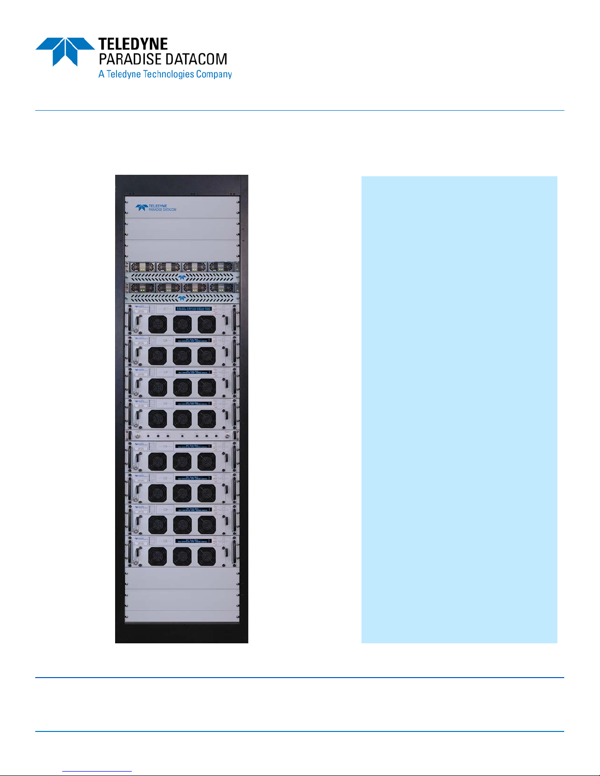
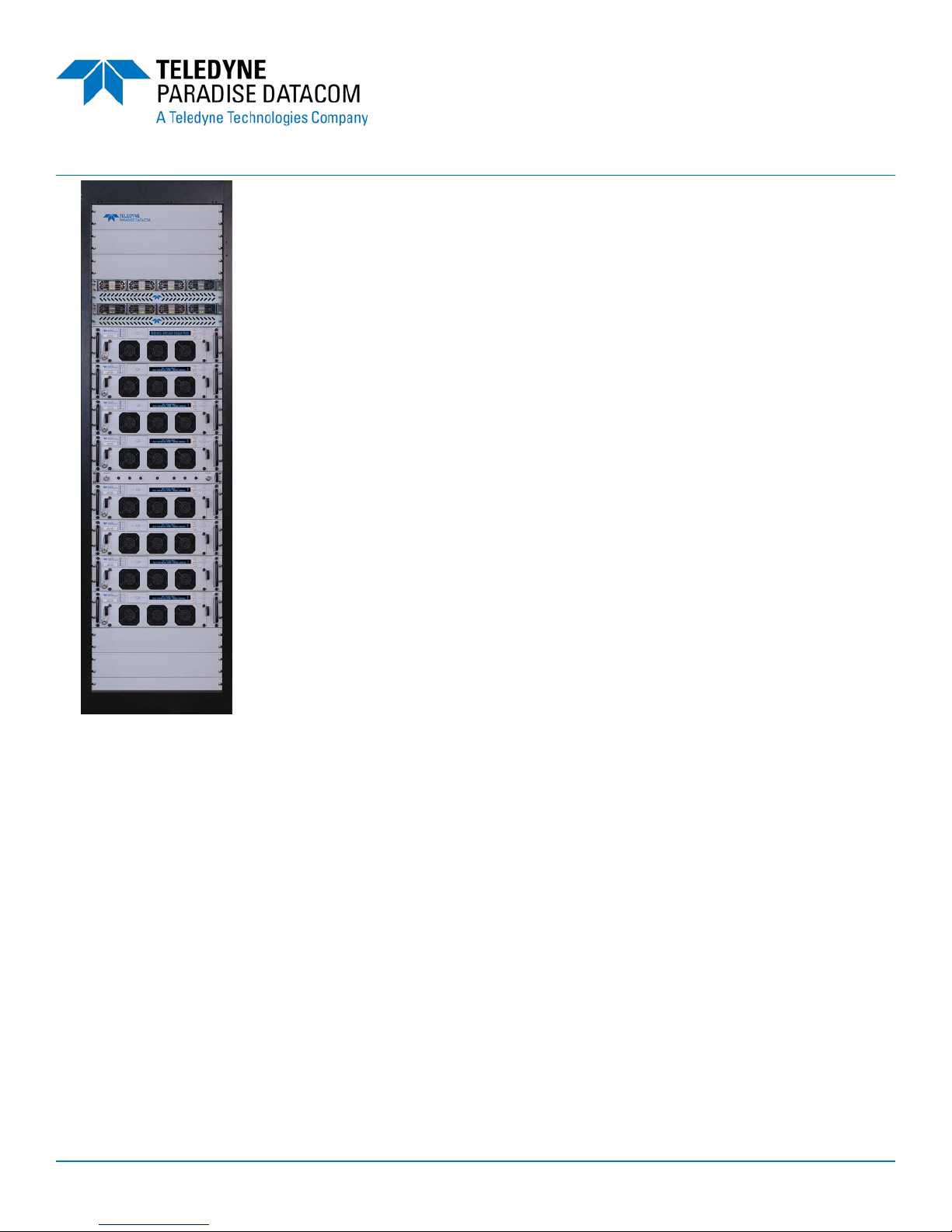
2.5 kW Ku-Band Solid State High Power Amplifier System
configured with (8) Modules
Teledyne Paradise Datacom Teledyne Paradise Datacom Ltd.
328 Innovation Blvd., Suite 100 2&3 The Matchyns, London Road, Rivenhall End
State College, PA 16803 USA Witham, Essex CM8 3HA United Kingdom
Tel: 1 (814) 238-3450 Tel: +44(0) 1376 515636
Fax: 1 (814) 238-3829 Fax: +44(0) 1376 533764
PAGE 1 OF 16 214578 REV A ECO 18422
PowerMAX is covered by U.S. Patent Nos.
8,189,338 B2 and 8,411,477 B2
www.paradisedata.com
GaN PowerMAX
Second Generation GaN
Modular N+1 Phase Combined System
System Operation
The PowerMAX system maintains complete parallel redundancy down to
the embedded control level. Therefore the loss of an entire HPA chassis will
not interrupt remote communications with the system. Remote communications can be either RS-485 or Ethernet. The system will automatically
correct its gain level in the event of one or more HPA chassis failures.
The sophisticated system monitor and control allows the system to be
locally or remotely operated as if it were a “single” chassis amplifier. The
system control maintains a hierarchical management that allows the
operator to interface to a single chassis of the multi-module array.
Another feature unique to Teledyne Paradise Datacom’s PowerMAX is the
introduction of “true rms” output power measurement. Unlike other amplifier
systems that utilize diode detection schemes, the PowerMAX reports the
true rms output power of the system independent of the number of carriers
and modulation schemes.
Proprietary waveguide combining techniques are employed so that
maximum power combining efficiency is optimized within the operating
frequency band.
System Output Power and Configurations
Because the system power combining is purely passive and no switching is used, there is never an
interruption in RF output power. The PowerMAX system is typically used as a “self-redundant”
system. The output power is sized such that the loss of (1) RF module’s power will still allow the
system to maintain its minimum required output power. This type of system architecture is described
as n+1 redundant. The system can be configured with any number of modules but best overall
efficiency is obtained with the popular binary combinations of 4, 8, or 16 modules. It is very easy to
upgrade the PowerMAX system from 4 modules to 8 or 16 modules in the field. It is not necessary to
fully populate the system at the time of initial purchase. This provides the user a path to upgrade
output power capability as system requirements grow, thus keeping capital investment minimized.
For sizing redundant output power capability use the following guideline to determine the output
power of the system with the loss of (1) module.
4 Module System - 3 of 4 Modules Operable = 2.5 dB loss in output power capability
8 Module System - 7 of 8 Modules Operable = 1.2 dB loss in output power capability
16 Module System - 15 of 16 Modules Operable = 0.6 dB loss in output power capability
PAGE 2 OF 16 214578 REV A ECO 18422
Modular N+1 Phase Combined System
System Prime Input Power
Proprietary adaptive bias techniques are utilized to achieve
an aggressive balance between RF output power and minimized DC input power.
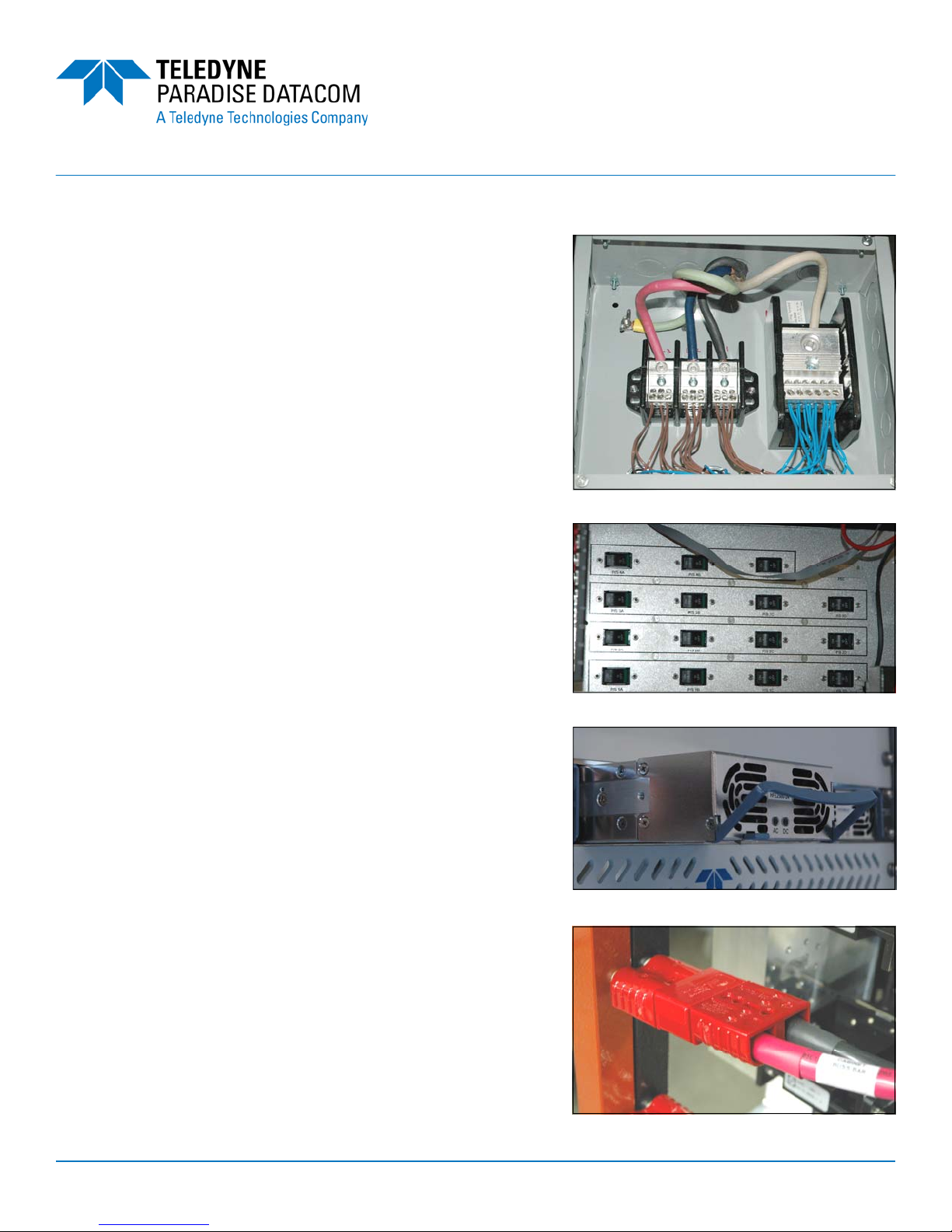
Prime power may be introduced into a terminal block at the
top of the cabinet. Electrical conduit is routed between the
terminal block and a 5RU boxed assembly, the AC Distribution/Circuit Breaker Panel, which houses a separate toggle
switch circuit breaker for each power supply module in the
system. Additional circuit breakers are available for auxiliary
equipment mounted in the cabinet.
System prime input power is achieved with an array of modular (hot-swap) power supply chassis. Power is distributed
from the power supplies to the SSPA modules via a bus rail
assembly.
Each of the power supply modules has its own single
phase, 180-264 VAC input. This makes it very convenient
to parallel the AC inputs of two modules and connect the
array to a three phase AC input source.
The power supply chassis is configured as a n+1 redundant, hot swappable power supply. In the event of a power
supply module failure, the amplifier system will not fail. The
failed module can be changed without ever taking the HPA
out of service. The microwave amplifier architecture is also
designed for maximum soft fail redundancy.
Prime system AC Input Power specifications are shown on
pages 6-8 for various PowerMAX power levels and configurations.
GaN PowerMAX
Second Generation GaN
Terminal Block
Circuit Breaker Panel
Power Supply Module in Chassis
PAGE 3 OF 16 214578 REV A ECO 18422
Quick Connect Plug into Bus Rail
GaN PowerMAX
Second Generation GaN
Modular N+1 Phase Combined System
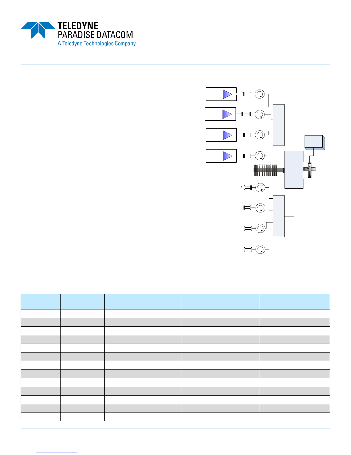
Hitless Redundancy
For mission critical systems in which no power outage
can be tolerated, an eight module PowerMAX system
can be operated with only four modules installed. In this
way, the additional four modules can be installed without
requiring the system to be powered off.
The only disadvantage of operating the eight module
PowerMAX system with four modules is the additional
3 dB loss that the four module (half-system) system
experiences by going through the final hybrid combiner
as shown at right. Therefore the overall output power is
actually 6 dB below what it would be with all eight
modules present in the system.
If, however, the module output power is sized such that
this reduction in output power can be tolerated, the
system shown at right is an effective means of scaling
the system from four to eight modules and maintaining
true hitless operation. The system never has to be
powered down and there are no mechanical switches
involved that would create an interruption of service.
With parallel system architectures, the amplifier output power capability and gain will change as the
number of active modules vary. The PowerMAX system is designed with an Auto-Gain Control mode
so that the overall system gain will remain constant in the event of a single module failure. See the
table below.
System
Type
4-Chassis 3 of 4 0 dB -2.5 dB -2.5 dB
4-Chassis 2 of 4 -1.0 dB -6.0 dB -6.0 dB
4-Chassis 1 of 4 -7.0 dB -12.0 dB -12.0 dB
8-Chassis 7 of 8 0 dB -1.2 dB -1.2 dB
8-Chassis 6 of 8 0 dB -2.4 dB -2.4 dB
8-Chassis 5 of 8 0 dB -4.0 dB -4.0 dB
8-Chassis 4 of 8 -1.0 dB -6.0 dB -6.0 dB
8-Chassis 3 of 8 -3.5 dB -8.5 dB -8.5 dB
8-Chassis 2 of 8 -7.5 dB -12.5 dB -12.5 dB
16-Chassis 15 of 16 0 dB -0.6 dB -0.6 dB
16-Chassis 14 of 16 0 dB -1.2 dB -1.2 dB
16-Chassis 13 of 16 0 dB -2.0 dB -2.0 dB
16-Chassis 12 of 16 0 dB -2.5 dB -2.5 dB
# Modules
in System
Gain Change
Auto Gain Control On
Chassis
Module
Chassis
Module
Chassis
Module
Chassis
Module
Shorting plate on each
waveguide extension
Gain Change
Auto Gain Control Off
4-Way
Combiner
1
2
Σ
3
4
IN
ΣΔ
IN
2-Way
1
2
3
4
Σ
4-Way
Combiner
Combiner
Maximum
Output Power
Power
Detector
RF
OUT
PAGE 4 OF 16 214578 REV A ECO 18422
GaN PowerMAX
Second Generation GaN
Modular N+1 Phase Combined System
SSPA Chassis Population Options
The PowerMAX system is available in a variety of system GaN module configurations and output
power levels. The system is based on Teledyne Paradise Datacom’s 3RU chassis with 100% hot
swappable active assemblies. The units can be configured with a wide variety of SSPA frequency
bands and power levels, and can be fitted with the following SSPA modules:
• S-Band: 50W, 100W, 200W, 300W, 400W, 500W, 600W, 800W, 1 kW
• C-Band: 50W, 100W, 150W, 200W, 300W, 400W, 650W, 800W
• X-Band: 300W, 400W, 650W, 800W
• Ku Band: 50W, 80W, 100W, 150W, 200W, 300W, 400W, 500W
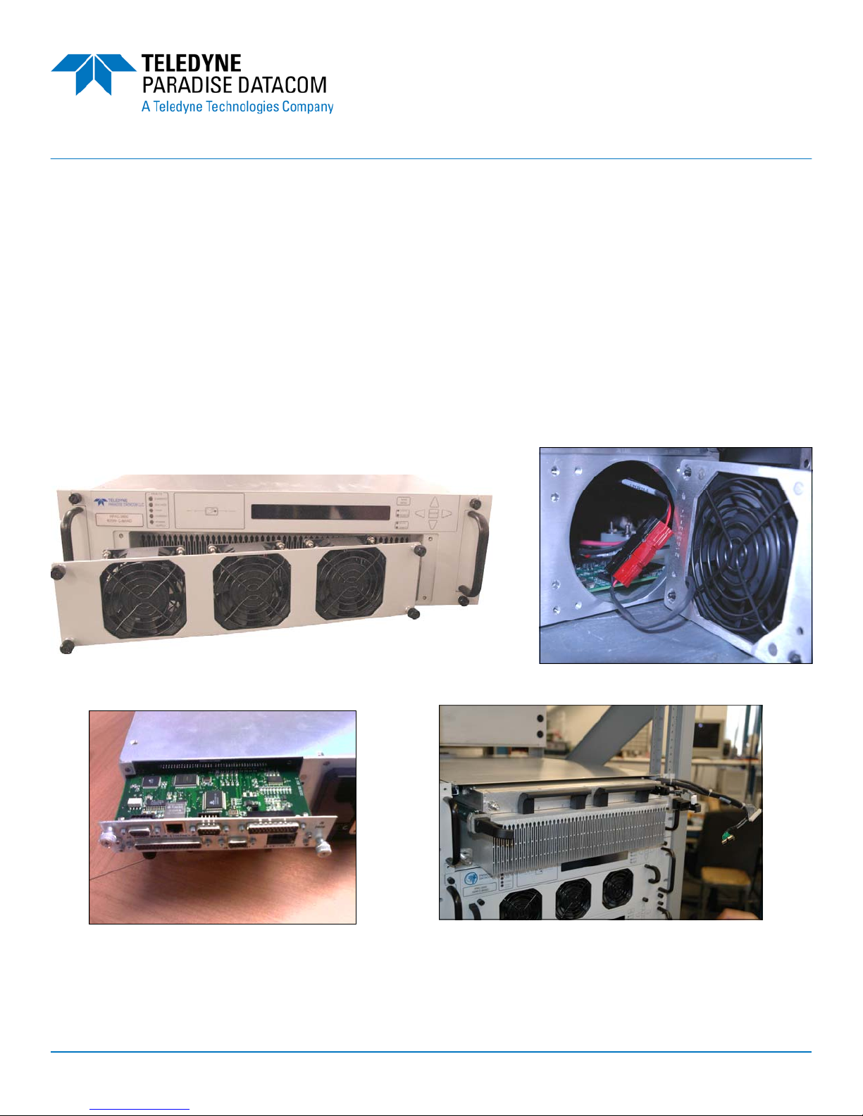
Hot-Swap Chassis Features
Removable front panel fan tray
Removable rear panel monitor
and control card
PAGE 5 OF 16 214578 REV A ECO 18422
SSPA Module Removal via the front panel
Removable rear panel fan tray
 Loading...