

Teledyne G3-GM10-M0640, G3-GM12-M0801, G3-GM10-M0801, G3-GM12-M0800, G3-GM12-M0640 User Manual
...
Genie Nano Series
™
Camera User’s Manual
sensors | cameras | frame grabbers | processors | software | vision solutions
1 Gb GigE Vision – Monochrome & Color Area Scan
November 7, 2017
Rev: 0018
P/N: G3-G00M-USR00
www.teledynedalsa.com

Notice
© 2015-2017 Teledyne DAL SA
All information provided in this manual is believed to be accurate and reliable. No responsibility is
assumed by Teledyne DALSA for its use. Teledyne DALSA reserves the right to make changes to
this information without notice. Reprod uction of this manual in whole or in part, by any means, is
prohibited without prior permission having bee n obtained from Teledyne DALSA.
Microsoft and Windows are registered trademarks of M icro soft Corporation in the United States and
other countries. Windows, Windows 7, Windows 10 are trademarks of Microsoft Corporation.
All other trademarks or intellectual property mentioned herein belong to their respective owners.
Document Date: November 7, 2017
Document Number: G3-G00M-USR00
About Teledyne DALSA
Teledyne DALSA is an international high performance semiconductor and Electronics Company that
designs, develops, manufactures, a nd m arke ts digita l imaging products and solutions, in addition
to providing wafer foundry services.
Teledyne DALSA Digital Imaging offers the widest rang e of machine vision components in the
world. From industry-leading image sensors through powerful and sophisticated cameras, frame
grabbers, vision processors and software to easy-to-use vision appliances and custom vision
modules.

•
Contents
GENIE NANO SERIES OVERVIEW 8
DESCRIPTION 8
GigE with TurboDrive 8
Genie Nano Overview 9
GigE Firmware 9
MODEL PART NUMBERS 10
Monochrome Ca m e ras 10
Color Cameras 12
Accessories 15
SOFTWARE REQUIREMENTS 16
Sapera LT Development Software 16
Third Party GigE Vision Development 16
About GigE Vision 16
GENIE NANO SPECIFICATIONS 17
COMMON SPECIFICATIONS 17
Sensor Cosmetic Specifications 19
Dynamic Rang e & Signal to Noise Ratio Mea surement Conditions 19
EMI, Shock and Vibration Certifications 20
Mean Time between Failure (MTBF) 21
SPECIFICATIONS: M1450, C1450 22
Firmware Files for Models 1450 23
Spectral Response 23
SPECIFICATIONS: M1920, C1920 24
SPECIFICATIONS: M1940, C1940 25
Firmware Files for 1920, 1940 26
Spectral Response 27
SPECIFICATIONS: M2020, C2020 28
Firmware Files for Models 2020 29
SPECIFICATIONS: M2050 29
Firmware Files for Model M2050 30
SPECIFICATIONS: C2050 31
Firmware Files for Model C2050 32
Spectral Responses 33
SPECIFICATIONS: M2420, C2420 34
Firmware Files for Models 2420 35
SPECIFICATIONS: M2450 35
Firmware Files for Model M2450 36
SPECIFICATIONS: C2450 37
Firmware Files for Model C2450 38
Spectral Responses 39
SPECIFICATIONS: M4060 40
Firmware Files for Model M4060 41
SPECIFICATIONS: C4060 41
Firmware Files for Model C4060 42
SPECIFICATIONS: M4040 43
Firmware Files for Model M4040 44
Nano Series GigE Vision Camera Contents
1

SPECIFICATIONS: C4040 45
Firmware Files for Model C4040 46
Spectral Responses 4060 & 4040 47
SPECIFICATIONS: M4030, C4030 48
SPECIFICATIONS: M4020, C4020 49
Firmware Files for Model 4030 & 4020 50
Spectral Response 51
SPECIFICATIONS: M640, M640-NIR, C640 52
SPECIFICATIONS: M800, M800-NIR, C800 53
Firmware Files for Models 640, 800 55
SPECIFICATIONS: M1240, C1240 55
Firmware Files for Models 1240 56
SPECIFICATIONS: M1280, M1280-NIR, C1280 57
SPECIFICATIONS: M1930, M1930-NIR, C1930 58
SPECIFICATIONS: M2590, M2590-NIR, C2590 60
Firmware Files for Models 1280, 1930, 2590 61
NANOXL SPECIFICATIONS: M5100, M5100-NIR, C5100, M4090, M4090-NIR, C4090 62
Spectral Response 64
Firmware Files for These Models 65
SPECIFICATIONS: C4900 66
Spectral Response 67
Supplemental Usage Notes: 67
Model C4900 Sensor Cosmetic Specifications 68
Firmware Files for This Model 68
Guide to Using a Rolling Shutter Camera 69
Characteristics 69
Overview of Ele c tr onic Rolling Sh utter (ERS) Exposures 70
Overview of Global Reset Relea s e ( G R R ) Exposures 71
COMPARISON OF SIMILAR ON-SEMI AND SONY SENSORS 72
NANO QUICK START 74
TESTING NANO WITHOUT A LENS 74
TESTING NANO WITH A LENS 74
THE CAMERA WORKS — NOW WHAT 74
CONNECTING THE GENIE NANO CAMERA 75
GIGE NETWORK ADAPTER OVERVIEW 75
PAUSE Frame Support 75
CONNECT THE GENIE NANO CAMERA 75
Connectors 76
LED Indicators 77
Camera Status LED Indicator 77
LED States on Pow er Up 77
Genie Nano IP Configuration Sequence 78
Supported Networ k Configurations 78
PREVENTING OPERATIONAL FAULTS DUE TO ESD 79
USING NANO WITH SAPERA API 80
NETWORK AND COMPUTER OVERVIEW 80
INSTALLATION 81
Procedure 81
Camera Firmware Updates 81
Firmware via Linux or Third Party Tools 81
2 • Contents Nano Series GigE Vision Camera

•
GigE Server Verification 82
GigE Server Status 82
OPTIMIZING THE NETWORK ADAPTER USED WITH NANO 83
QUICK TEST WITH CAMEXPERT (WINDOWS) 83
About the Device User ID 84
OPERATIONAL REFERENCE 85
USING CAMEXPERT WITH GENIE NANO CAMERAS 85
CamExpert Panes 85
CamExpert View Para meter s O ption 86
CAMERA INFORMATION CATEGORY 87
Camera Information Feature Descriptions 87
Power-up Configuration Dialog 91
Camera Power-up Configuration 91
Load / Save Configuration 91
SENSOR CONTROL CATEGORY 92
Sensor Control Feature Descriptions 93
Offset/Gain Control Details (Sony sensors) 96
Sony Sensors Gain Stage Diagram 96
Offset/Gain Control Details (On-Semi Python sen sor s) 97
On-Semi Python Sensors Gain Stage Diag r a m 97
Bayer Mosaic Pattern 98
OnSemi Python P1 Sensor Artifacts with Fast Readout Mode 98
Fast Readout Mode A r tifacts Correc tion 99
Exposure Alignment: Overview 99
Synchronous Exposure Alignment 99
Reset Exposure Alignment 100
Sensor Exposure Timing: Sony Sensor Models 100
Trigger Characteristics: Start of Exposure 100
Sensor Exposure Timing: OnSemi Python Models 101
Trigger Characteristics: Start of Exposure 101
AUTO-BRIGHTNESS CONTROL CATEGORY 102
Auto-Brightness Feature Descriptions 102
Using Auto-Brightness 104
General Preparati on 104
Auto-Brightness with Frame Luminance Averaging 105
Auto-Gain 105
Auto-Brightness by using Auto-Exposure and Auto-Gain 105
I/O CONTROL CATEGORY 106
I/O Control Feature Descriptions 107
I/O Module Block Diagram 111
Trigger Mode Details 111
Trigger Source Types (Trigger Mode=On ) 111
Input Line Details 112
Trigger Overlap: Feature D eta ils 113
Output Line Detai ls 120
Output High an d Ou tput Low Block Diagram 120
COUNTER AND TIMER CONTROL CATEGORY 121
Counter and Timer Control Feature Description 121
Counter and T im er Group Block Diagram 125
Example: Counter Start Source = OFF 126
Example: Counter Start Source = CounterEnd (its elf) 126
Example: CounterStartSource = EVENT and Signal (Edge Base) 127
Example: CounterStar tS ou r c e = Line (Edge Base) Example 127
ADVANCED PROCESSING CONTROL CATEGORY 128
Nano Series GigE Vision Camera Contents
3

Advanced Processing Control Feature Descriptions 128
Lookup Table (LUT) Overview 131
LUT Size vs. Outp ut Pixel Format 131
Defective Pixel Replacement (Method 3) 132
Example User Defective Pi xel Map XML File 132
Defective Pixel Replacement Algor ithm Description 133
COLOR PROCESSING CONTROL CATEGORY 134
Color Processing Control Feature Description 134
Color Processing Functional Overview 135
White Balance O pe r a tion 136
Simplified RGB De s ig n Firmware Block Diagram 136
Saturation an d L uminance Operati on 137
FLAT FIELD CORRECTION CATEGORY 138
Flat Field Correction Feature Description 138
CYCLING PRESET MODE CONTROL CATEGORY 140
Cycling Preset Mode Control Feature Description 141
Using Cycling Presets—a Simple Example 145
Multi-Exposure Cy c lin g Example S etup 145
Cycling Reset Timing Details 146
Case 1: Cycling with Internal Synchronous Increment 146
Case 2: Cycling with External Asynchronous Increment 146
Using Cycling Presets with Output Controls 147
Feature Settings for this Example 147
Cycling Mode Constraints with a changing ROI 148
Specifics Conc erning OnSemi Sen sor Models 148
Specifics Conc erning Sony Sensor Models 148
IMAGE FORMAT CONTROL CATEGORY 149
Image Format Control Feature Description 150
Width and Height Features for Partial Scan Contr ol 155
Vertical Cropping (Partial Scan) 155
Maximum Frame Rate Examples (Models M/C 1920 & 1940) 156
Maximum Frame Rate Examples (Models M2420 & M2450) 156
Maximum Frame Rate Examples (Models M2020 & M2050) 157
Maximum Frame Rate Examples (Models M/C 4040 & 4060) 157
Maximum Frame Rate Examples (Models M/C 4020 & 4030) 158
Maximum Frame Rate Examples (Model M/C 2590) 158
Maximum Frame Rate Examples (Model C 4900) 159
Maximum Frame Rate Examples (Model M/C 1930) 159
Maximum Frame Rate Examples (Model M/C 1240) 160
Maximum Frame Rate Examples (Model M/C 1280) 160
Maximum Frame Rate Examples (Model M/C 800) 161
Maximum Frame Rate Examples (Model M/C 640) 161
Maximum Frame Rate Examples (NanoXL–M5100) 162
Maximum Frame Rate Examples (NanoXL–M4090) 163
Horizontal Cropping (Partial Scan) 164
Using the Multiple ROI Mode 164
Important Usage D etails 165
Example: Two H or izontal ROI Areas (2x1) 165
Example: Four ROI Areas (2x2) 166
Example: Actual Sample with Six ROI Areas (3x2) 166
Horizontal and Vertical Flip 168
Image Flip – Full Frame 168
Image Flip – Multi-ROI Mode 169
Binning Function and Limitations 170
Horizontal Binning Constraints 170
Vertical Binning Constraints 170
4 • Contents Nano Series GigE Vision Camera

•
Internal Test Pattern Generator 171
METADATA CONTROL CATEGORY 172
Metadata Control Category Feature Descr i ptions 172
Important Metada ta Notes: 175
Extracting Metadata Stored in a Sapera Buffer 176
ACQUISITION AND TRANSFER CONTROL CATEGORY 178
Acquisition and Transfer Control Feature Descriptions 179
Acquisition B uffering 180
Using Transfer Queue Current Block Count with CamExpert 181
“Acquisition Ab or t” Execution E xception with Model C 49 00 181
Features that cannot be changed during a Tra nsfer 181
ACTION CONTROL CATEGORY 182
Action Control Feature Descriptions 183
GigE Vision Action Command Refer ence 183
Nano Features s upporting Action C om m a nd 183
EVENT CONTROL CATEGORY 184
Event Control Feature Descriptions 185
Basic Exposure Events Overview 190
Events Associated with T r iggered Synchronous Exposures 190
Events Associated with T r iggered M ultiple Frame Synch r on ous Exposures 191
Overview of Precision Time Protocol Mode (IEEE 1588) 192
PTP Master Cloc k Identity 192
An Example with two Nano Cameras 192
IEEE 1588 Reference Resources 193
Examples using Timestamp Modulo Event for Acquisitions 193
Case Examples Overv iew 193
Case 1: Simple Repeating Ac quisitions as Upcoming Events 193
Case 2: Potential Uncertainnes s to the Start Time 194
Case 3: Timer Reset before th e Actual Start Time 195
Case 4: Timer Res et a fter the Actual S tart Time 196
Case 5: Changin g ‘timestampModulo’ d uring Acquisitions 197
GIGE VISION TRANSPORT LAYER CONTROL CATEGORY 198
GigE Vision Transport Layer Feature Descriptions 198
Defaults for devicePacketResendBufferSize 203
GIGE VISION HOST CONTROL CATEGORY 204
Teledyne DALSA TurboDrive 204
FILE ACCESS CONTROL CATEGORY 204
File Access Control Feature Descriptions 205
Updating Firmware via File Access in CamExpert 208
Overview of the deviceUserBuffer Feature 208
IMPLEMENTING TRIGGER-TO-IMAGE RELIABILITY 209
OVERVIEW 209
T2IR with Genie Nano 209
NANO FEATURES FOR T2IR MONITORING 209
SAPERA TOOLS FOR NETWORKING 211
NANO IP CONFIGURATION MODE DETAILS 211
TECHNICAL SPECIFICATIONS 212
MECHANICAL SPECIFICATIONS — C & CS MOUNT: 212
MECHANICAL SPECIFICATIONS — NANOXL: 214
ADDITIONAL NOTES ON GENIE NANO IDENTIFICATION AND MECHANICAL 215
Temperatur e Ma n ag ement 215
SENSOR ALIGNMENT SPECIFICATION 215
Nano Series GigE Vision Camera Contents
5

CONNECTORS 216
10-pin I/O Connector Details 218
Camera DC Power Characteristics 218
I/O Mating Connector Specificati ons & Sources 219
Power over Ethernet (PoE) Support 220
Input Signals Electrical Specifications 221
External Inpu t D etails 221
External Input DC Characteristics 221
External Inpu t AC Timing Character istics 222
External Inpu ts: Using TTL/LVTTL Drivers 222
External Inpu ts: Using Common Collec tor NPN Drivers 223
External Inpu ts: Using Common Emitte r NPN Driver 223
External Inputs: Using a Balanced Driver 224
Output Signals Electrical Specifications 224
External Output Details and DC Characteristics 224
External Output AC Timing Characteristics 225
External Outputs: Using Extern al TTL/LVTTL Drivers 226
External Outputs: Using Extern al LED Indicators 226
Using Nano Outputs to drive othe r Nano Inputs 228
COMPUTER REQUIREMENTS FOR NANO CAMERAS 229
Host PC System 229
Recommended Network Adapters 229
Ethernet Switch Requirements 230
IEEE 802.3x Pause Fram e Flow C ontrol 230
Ethernet to Fiber-Optic Interface Requirements 230
EC & FCC DECLARATIONS OF CONFORMITY 231
Models: M/C1920, M/C1940 231
Models: M/C2590, M/C1930, M/C1280, M/C800, M/C640 232
Models: M/C2020, M/C2050, M/C2420, M/C2450 233
Models: M/C4020, M/C4030, M/C4040, M/C4060 234
Models: M/C5100, M/C4090 235
ADDITIONAL REFERENCE INFORMATION 236
CHOOSING A LENS WITH THE CORRECT IMAGE CIRCLE 236
Lens Options for Models ‘M/C1940’ & ‘M/C1920’ 236
Lens Options for Models ‘2450/2420’ & ‘2050/2020’ 237
Lens Options for Models ‘4060/4040/4030/4020’ 237
Lens Options for Models ‘M/C1450’ 238
Lens Options for XL Models ‘M/C 5100’ and ‘M/C 4090 238
Lens Options for Model ‘C4900’ 239
Lens Options for Models ‘M/C2590’ & ‘M/C 2540’ 239
Lens Options for Models ‘M/C1930’ 240
Lens Options for Models ‘M/C1280’ & ‘M/C1240’ 240
Lens Options for Models ‘M/C800’ 241
Lens Options for Models ‘M/C640’ 241
Additional Lens Parameters (application specific) 242
OPTICAL CONSIDERATIONS 242
Illumination 242
Light Sources 243
IR Cut-off Filters 243
Nano Models with Built-in IR Cut-off Filters 243
Guidelines for Choosing IR Cu t-off Filters 244
Back Focal Variance when using any Filter 245
LENS MODELING 246
Magnification and Resolution 246
6 • Contents Nano Series GigE Vision Camera

•
SENSOR HANDLING INSTRUCTIONS 247
Electrostatic Discharge and the Sensor 247
Protecting Against Dust, Oil and Scratches 247
Cleaning the Sensor Window 248
RUGGEDIZED CABLE ACCESSORIES 248
Cable Assembly G3-AIOC-BLUNT2M 249
Cable Assembly G3-AIOC-BRKOUT2M 251
Nano Generic Power Supply with no I/O 253
Components Express Right-Angle Cable Assemblies 254
Cable Assembly: Right-Angle I/O Bunt End 254
Cable Assembly: Right-Angle I/O to Euro Block 255
Ruggedized RJ45 Ethernet Cables 256
Components Ex pr e s s Contact Inf ormation 256
Cable Assembly: Right-Angle Ethernet 257
Right-Angle Cable-Set (Mounted) 258
TROUBLESHOOTING 259
OVERVIEW 259
Problem Type Summary 259
Verifying Network Parameters 261
Before Contacting Technical S upport 261
DEVICE AVAILABLE WITH OPERATIONAL ISSUES 261
Firmware Updates 261
Power Failure during a Firmware Update–Now W h at ? 262
Cabling and Communication Issues 262
Acquisition Error without Timeout Messages 262
Grab has Random Bad Data or Noise 263
No camera exposure when ex pec ted 263
Camera is func tional but frame rate is lower than expected 264
Camera acquis ition is good but fr a m e r a te is lower than expecte d 264
Camera is functional, frame rate is as expected, but image is black 264
Model C4900 Column Noise in Saturated Areas 265
Other Problems or Issues 266
Preventing Dropped Packets by adjusting Power Opti on s 266
Random Invalid Trigger Events 267
Minimum Sapera Version Requ ired 267
Issues with uninstalling Cognex VisionPro with S a p er a LT CamExpert 267
ADDENDUMS 268
AC CHARACTERISTICS OF 1 INPUT / 3 OUTPUT MODELS 268
DEFECTIVE PIXEL REPLACEMENT (METHOD 4) 269
Example User Defective Pixel Map XML File 269
Monochrome Defective Pixel Replacement Algorithm Description 269
Color Defective Pixel Replacement Algorithm Description 272
REVISION HISTORY 273
CONTACT INFORMATION 274
SALES INFORMATION 274
TECHNICAL SUPPORT 274
INDEX 275
Nano Series GigE Vision Camera Contents
7

Genie Nano Series Overview
Description
The Genie Nano series, a member of the Genie camera family, provides a new series of affordable
easy t o use digital cameras specifically engineer ed for industrial imaging applic ations requiring
improved network integration.
Genie Nano cameras use the industries’ latest leading sensors such as the Sony Pregius series and
On-Semi Python series of global shutter active pixel-type CMOS image sensors.
Genie Nano cameras combine standard gigabit Ethernet technology (supporting GigE Vision 1.2)
with the Teledyne DALSA Trigger-to-Image-Reliability framework to dependably capture and
transfer images from the camera to the host PC. Genie Nano cameras are available in a number of
models implementing different sensors, image resolutions, and feature sets, either in monochrome,
monochrome N IR, or color versions.
GigE with TurboDrive
Genie Nano cameras include TurboDrive™ technology, delivering high speed data transfers
exceeding the GigE limit. TurboDrive uses advanced data modeling to boost data transfers up to 2
or 3 times faster than standard GigE Vision speeds – with no loss of image quality. These
breakthrough rates are achieved using a proprietary process that assembles data from the sensor
to optimize throughput, simultaneously taking full advantage of both the sensor’s maximum frame
rate and the camera’s maximum GigE data transfer speed (up to 1 1 5 Mbytes/s). Teledyne DALSA’s
TurboDrive increases system dependability and robustness similar to Camera Link throughput on a
GigE network.
Important: Actual Transfers with TurboDrive is image content dependent but in the best case
scenario, transfers over a GigE Network can reach the camera’s internal acquisition limit of up to
252MB/sec. If transfers are less than the camera maximum acquisition rate, camera memory will
be used as a circular frame buffer. Note: Not supported with RGB output firmware on any model
due to camera resource limitations.
Refer to TurboDrive Primer on the Teledyne DALSA web site for more details.
8 • Genie Nano Series Overview Nano Series GigE Vision Camera

•
Genie Nano Overview
• Optimized, rugged design with a wider operating temperature
• Availa ble in multiple sensors/resolutions, monochrome and color
• Higher frame rates with Teledyne DALSA GigE Vision TurboDrive Technology
• Visual camera multicolor status LED on back plate
• Multi-ROI support
• 2 (default models) general purpose opto-coupled inputs
• 2 (default models) general purpose opto-coupled outputs (user, counter, or timer driven for
Strobe and Flash triggering)
• Flexible general purpose Counter and Timer functions available for internal and external
controls
• Software and hardware Events available to support imaging applications
• Cycling mode supports 64 multiple camera setups (including Multi-Exposure)
• Auto brightness (i.e. auto exposure and AGC) available o n ma ny models
• In-sensor and/or FPGA (digital) Binning available on monochrome models
• Supports Image Time-Stamp based on IEEE1588-2008 (PTP: Precise Time Protocol) or an
Internal Timer
• Programmable Look-Up-Table (programmable LUT or preset Gamma) available
• Defective Pixel replacement available on some models
• Multicast and Action Command supported
• Image metadata supported
• Supports Pow e r Ove r Ethernet (PoE) or auxiliary power input
• Implements 32 MB of Flash Memory
• 2 User Settings sets to store and recall camera configurations
• Supports the Gigabit Ethernet PAUSE Frame feature
• GigE Vision 1.2 compliant
• Gigabit Ethernet (GigE) interconnection to a computer via standard CAT5e or CAT6 cables
• Gigabit Ethernet (GigE) transfer speed up to 115 MB/second
• Application development with the freely available Sapera™ LT software libraries
• Native Teledyne DALSA Trigger-to-Image Reliability design framework
• Refer to the Operation Reference and Technical Specifications section of the manual for full
details
• Refer to the Sapera LT 8.10 release notes for information on GigE Vision and TurboDrive
Technology support.
GigE Firmware
Firmware updates for Genie Nano are available for download from the Teledyne DALSA web site
www.teledynedalsa.com/imaging/support/downloads. Choose Genie Nano Firmware from the
available download sections, then choose the zip file download specific to your camera model.
When using Sapera LT, update the camera firmware using CamExpert (see File Access via the
CamExpert Tool).
The Camera firmware can also be easily upgrade/downgrade within your own application via the
API. The camera has a failsafe scheme which prevents unrecoverable camera errors even in the
case of a power interruption.
Nano Series GigE Vision Camera Genie Nano Series Overview
9

Model Part Numbers
This manual covers the released Genie Nano monochrome and color models summarized in the two
tables below. These tables list models in increasing resolution. Nano common specifications and
details for each Genie Nano model follow these tables.
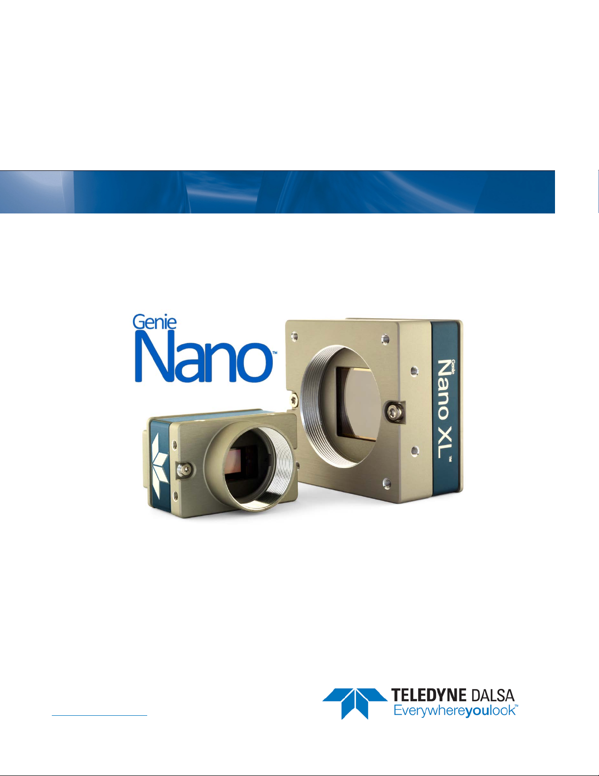
Monochrome Cameras
Model
Full Resolution
M640
672 x 512
M640 NIR
672 x 512
M800
832 x 632
M800 NIR
832 x 632
M1240
1280 x 1024
M1280
1280 x 1024
M1280 NIR
1280 x 1024
M1450
1456 x 1088
M1930
1984 x 1264
M1930 NIR
1984 x 1264
M1940
1936 x 1216
M1920
1936 x 1216
M2050
2048 x 1536
M2020
2048 x 1536
Sensor Size/Model Lens Part Number
On-Semi 0.3M
(Python300 P1)
On-Semi 0.3M
(Python300 P1)
On-Semi 0.5M
(Python500 P1)
On-Semi 0.5M
(Python500 P1)
On-Semi 1.3M
(Python1300 P3)
On-Semi 1.3M
(Python1300 P1)
On-Semi 1.3M
(Python1300 P1)
Sony 1.6M
(IMX273)
On-Semi 2.3M
(Python2000 P1)
On-Semi 2.3M
(Python2000 P1)
Sony 2.3M
(IMX174)
Sony 2.3M
(IMX249)
Sony 3.2M
(IMX252)
Sony 3.2M
(IMX265)
C-mount G3-GM10-M0640
CS-mount G3-GM10-M0641
C-mount G3-GM12-M0640
CS-mount G3-GM12-M0641
C-mount G3-GM10-M0800
CS-mount G3-GM10-M0801
C-mount G3-GM12-M0800
CS-mount G3-GM12-M0801
C-mount G3-GM11-M1240
CS-mount G3-GM11-M1241
C-mount G3-GM10-M1280
CS-mount G3-GM10-M1281
C-mount G3-GM12-M1280
CS-mount G3-GM12-M1281
C-mount
CS-mount
G3-GM10-M1450
G3-GM10-M1451
C-mount G3-GM10-M1930
CS-mount G3-GM10-M1931
C-mount G3-GM12-M1930
CS-mount G3-GM12-M1931
C-mount
CS-mount
C-mount
CS-mount
G3-GM10-M1940
G3-GM10-M1941
G3-GM11-M1920
G3-GM11-M1921
C-mount G3-GM10-M2050
CS-mount G3-GM10-M2051
C-mount G3-GM11-M2020
CS-mount G3-GM11-M2021
10 • Genie Nano Series Overview Nano Series GigE Vision Camera
•
Monochrome Cameras Continued
M2450
2448 x 2048
M2420
2448 x 2048
M2590
2592 x 2048
M2590 NIR
2592 x 2048
M4060
4112 x2176
M4030
4112 x2176
M4040
4112 x 3008
M4020
4112 x 3008
Sony 5.1M
(IMX250)
Sony 5.1M
(IMX264)
On-Semi 5.1M
(Python5000 P1)
On-Semi 5.1M
(Python5000 P1)
Sony 8.9M
(IMX255)
Sony 8.9M
(IMX267)
Sony 12M
(IMX253)
Sony 12M
(IMX304)
NanoXL Model
Full Resolution
M4090
4096 x 4096
M4090-NIR
4096 x 4096
M5100
5120 x 5120
M5100-NIR
5120 x 5120
Sensor Size/Model Lens Part Number
On-Semi 16M
(Python 16K)
On-Semi 16M
(Python 16K)
On-Semi 25M
(Python 25K)
On-Semi 25M
(Python 25K)
C-mount G3-GM10-M2450
CS-mount G3-GM10-M2451
C-mount G3-GM11-M2420
CS-mount G3-GM11-M2421
C-mount G3-GM10-M2590
CS-mount G3-GM10-M2591
C-mount G3-GM12-M2590
CS-mount G3-GM12-M2591
C-mount G3-GM10-M4060
CS-mount G3-GM10-M4061
C-mount G3-GM11-M4030
CS-mount G3-GM11-M4031
C-mount G3-GM10-M4040
CS-mount G3-GM10-M4041
C-mount G3-GM11-M4020
CS-mount G3-GM11-M4021
M42 mount G3-GM30-M4095
M42 mount G3-GM32-M4095
M42 mount G3-GM30-M5105
M42 mount G3-GM32-M5105
Nano Series GigE Vision Camera Genie Nano Series Overview
11
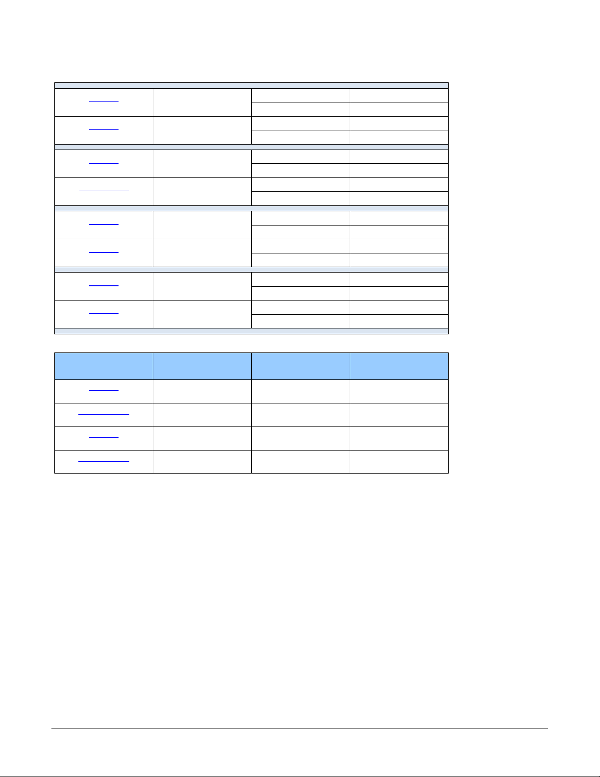
Color Cameras
Model
Full Resolution
C640
672 x 512
C800
832 x 632
C1240
1280 x 1024
C1280
1280 x 1024
C1450
1456 x 1088
C1930
1984 x 1264
C1940
1936 x 1216
C1920
1936 x 1216
Sensor Size/Model Lens Part Number
On-Semi 0.3M
(Python300 P1)
On-Semi 0.5M
(Python500 P1)
On-Semi 1.3M
(Python1300 P3)
On-Semi 1.3M
(Python1300 P1)
Sony 1.6M
(IMX273)
On-Semi 2M
(Python2000 P1)
Sony 2.3M
(IMX174)
Sony 2.3M
(IMX249)
C-mount
CS-mount
C-mount
CS-mount
C-mount
CS-mount
C-mount
CS-mount
C-mount
CS-mount
C-mount
CS-mount
C-mount
CS-mount
C-mount
CS-mount
Notes
G3-GC10-C0640
G3-GC10-C0640IF with IR Cut-off Filter
G3-GC10-C0641
G3-GC10-C0641IF with IR Cut-off Filter
G3-GC10-C0800
G3-GC10-C0800IF with IR Cut-off Filter
G3-GC10-C0801
G3-GC10-C0801IF with IR Cut-off Filter
G3-GC10-C1240
G3-GC10-C1240IF with IR Cut-off Filter
G3-GC10-C1241
G3-GC10-C1241IF with IR Cut-off Filter
G3-GC10-C1280
G3-GC10-C1280IF with IR Cut-off Filter
G3-GC10-C1281
G3-GC10-C1281IF with IR Cut-off Filter
G3-GM10-C1450
G3-GM10-C1450IF with IR Cut-off Filter
G3-GM10-C1451
G3-GM10-C1451IF with IR Cut-off Filter
G3-GC10-C1930
G3-GC10-C1930IF with IR Cut-off Filter
G3-GC10-C1931
G3-GC10-C1931IF with IR Cut-off Filter
G3-GC10-C1940
G3-GC10-C1940IF with IR Cut-off Filter
G3-GC10-C1941
G3-GC10-C1941IF with IR Cut-off Filter
G3-GC11-C1920
G3-GC11-C1920IF with IR Cut-off Filter
G3-GC11-C1921
G3-GC11-C1921IF with IR Cut-off Filter
12 • Genie Nano Series Overview Nano Series GigE Vision Camera
•
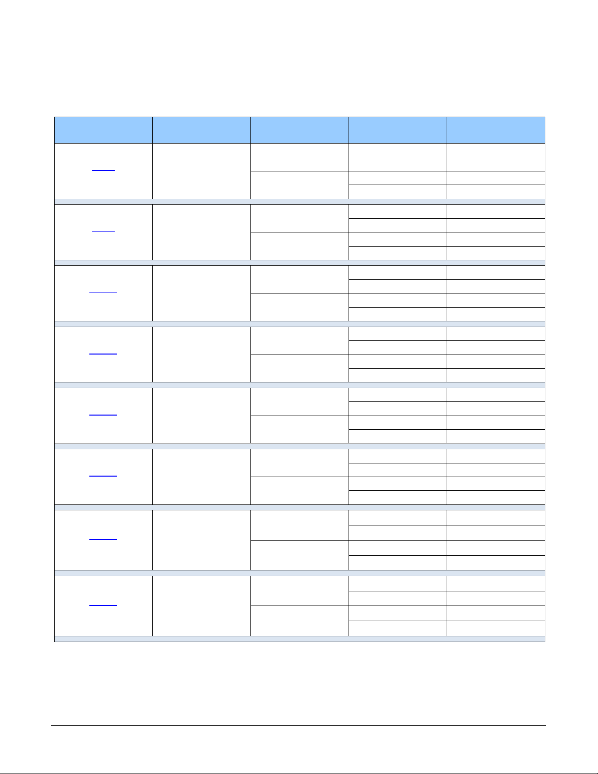
Color Cameras Continued
C2050
2048 x 1536
C2020
2048 x 1536
C2450
2448 x 2048
C2420
2448 x 2048
C2590
2592 x 2048
C4060
4112 x 2176
C4030
4112 x 2176
C4040
4114 x 3008
Sony 3.2M
(IMX252)
Sony 3.2M
(IMX265)
Sony 5.1M
(IMX250)
Sony 5.1M
(IMX264)
On-Semi 5.1M
(Python5000 P1)
Sony 8.9M
(IMX255)
Sony 8.9M
(IMX267)
Sony 12M
(IMX253)
C-mount
CS-mount
C-mount
CS-mount
C-mount
CS-mount
C-mount
CS-mount
C-mount
CS-mount
C-mount
CS-mount
C-mount
CS-mount
C-mount
CS-mount
G3-GC10-C2050
G3-GC10-C2050IF with IR Cut-off Filter
G3-GC10-C2051
G3-GC10-C2051IF with IR Cut-off Filter
G3-GC11-C2020
G3-GC11-C2020IF with IR Cut-off Filter
G3-GC11-C2021
G3-GC11-C2021IF with IR Cut-off Filter
G3-GC10-C2450
G3-GC10-C2450IF with IR Cut-off Filter
G3-GC10-C2451
G3-GC10-C2451IF with IR Cut-off Filter
G3-GC11-C2420
G3-GC11-C2420IF with IR Cut-off Filter
G3-GC11-C2421
G3-GC11-C2421IF with IR Cut-off Filter
G3-GC10-C2590
G3-GC10-C2590IF with IR Cut-off Filter
G3-GC10-C2591
G3-GC10-C2591IF with IR Cut-off Filter
G3-GC10-C4060
G3-GC10-C4060IF with IR Cut-off Filter
G3-GC10-C4061
G3-GC10-C4061IF with IR Cut-off Filter
G3-GC11-C4030
G3-GC11-C4030IF with IR Cut-off Filter
G3-GC11-C4031
G3-GC11-C4031IF with IR Cut-off Filter
G3-GC10-4040C
G3-GC10-C4040IF with IR Cut-off Filter
G3-GC10-C4041
G3-GC10-C4041IF with IR Cut-off Filter
Nano Series GigE Vision Camera Genie Nano Series Overview
13
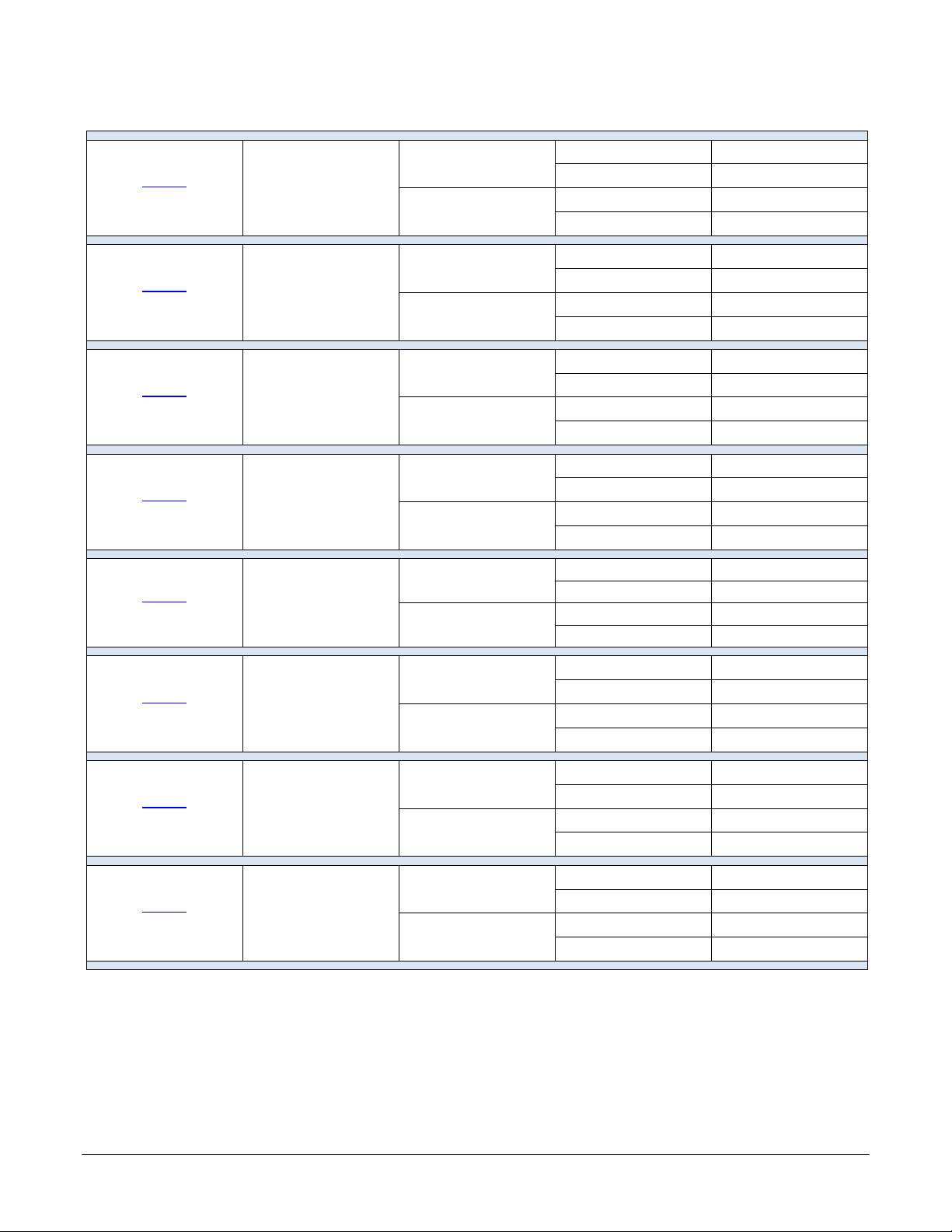
Color Cameras Continued
C4020
4114 x 3008
C4900
4912 x 3682
Sony 12M
(IMX304)
On-Semi 18M
(AR1820HS)
Rolling Shutter
NanoXL Model
Full Resolution
C4090
4096 x 4096
C5100
5120 x 5120
Sensor Size/Model Lens Part Number
On-Semi 16M
(Python 16K)
On-Semi 25M
(Python 25K)
C-mount
G3-GC11-C4020IF with IR Cut-off Filter
G3-GC11-C4021
G3-GC11-4020C
CS-mount
C-mount
CS-mount
G3-GC11-C4021IF with IR Cut-off Filter
G3-GC10-C4900
G3-GC10-C4900IF with IR Cut-off Filter
G3-GC10-C4901
G3-GC10-C4901IF with IR Cut-off Filter
M42 mount G3-GC30-C4095
M42 mount G3-GC30-C5105
14 • Genie Nano Series Overview Nano Series GigE Vision Camera
•
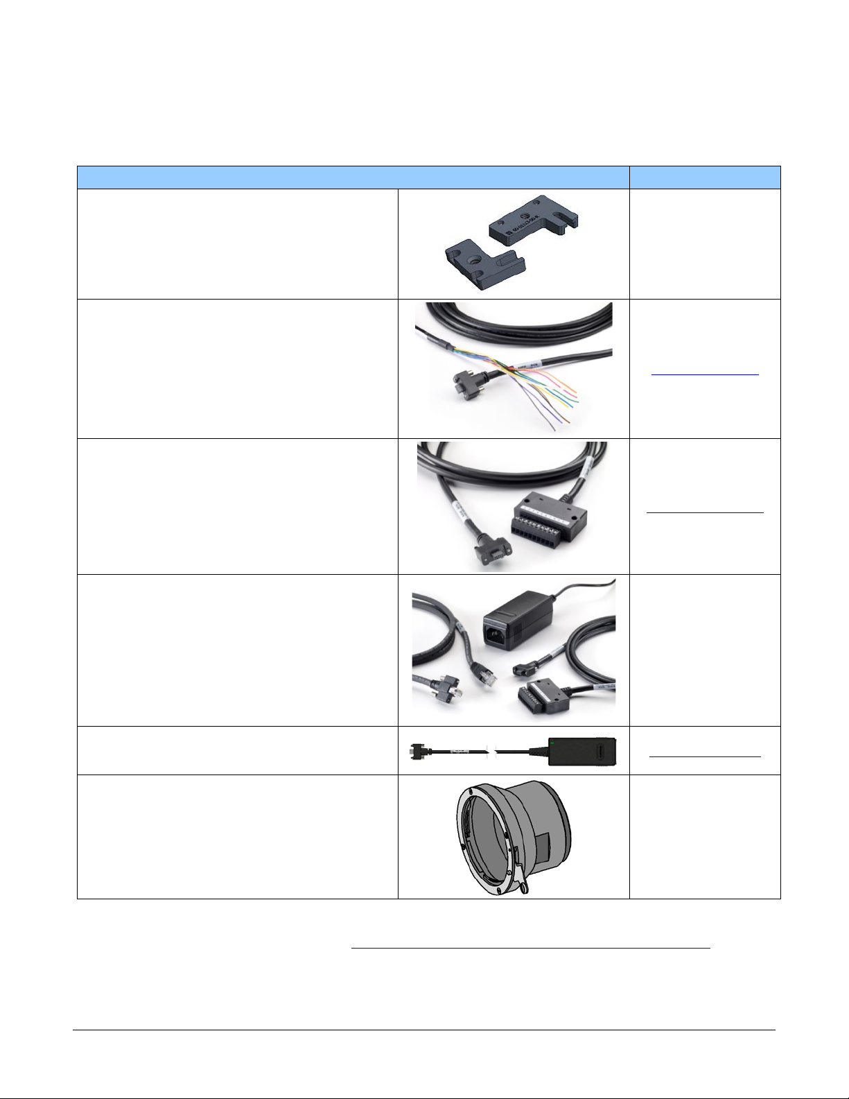
Accessories
Nano Accessories & Cables (sold separately) Order Number
Mounting Bracket Plate
(2 or 3 screw camera mount),
with ¼ inch external device screw mount
(also known as a tripod mount)
G3-AMNT-BRA01
I/O Blunt End Cable
(2 meter Screw Retention to Flying Leads)
I/O Breakout Cable
(2 meter Screw Retention to Euroblock connector )
Power and Cable Evaluation Kit
• Includes a Power Supply (12V),
• an Ethernet Cable (RJ-45, 2 meter),
• and a 2 meter I/O Breakout Cable (Euroblock)
Generic 12 volt power supply for Genie Nano–Aux
connector (Samtec 10-Pin) – 4 Meter length
G3-AIOC-BLUNT2M
G3-AIOC-BRKOUT2M
G3-ACBL-EVALKIT
G3-APWS-S10S04M
NanoXL — M42 to F-mount (Nikon) adapter
(same adapter part as used with Genie TS)
Note that there is no support for Nikon lens features
such as focus and aperture motor controls.
G2-AM42-MOUNT4
Right angle I/O cables and Ethernet cables (including combo evaluation packages) are available
directly from our preferred source (see Components Express Right-Angle Cable Assemblies).
Nano Series GigE Vision Camera Genie Nano Series Overview
15
Software Requirements
Sapera LT Development Software
Teledyne DALSA Software Platform for Microsoft Windows
Sapera LT version 8.00 or later (8.10 or later recommended),
for Windows. Includes Sapera Network Imaging Package and
GigE Vision Imaging Driver, Sapera Runtime and CamExpert.
Provides everything you will need to develop im aging appl ications
Sapera documentation provided in compiled HTML help,
and Adobe Acrobat® (PDF)
Sapera Processing Imaging Developm e nt Libr ary
(available for Windows or Linux – sold separ ate ly):
Teledyne DALSA Software Platform for Linux
GigE-V Framework Ver. 2.0 (for both X86 or Arm type processor) Available for download
Third Party GigE Vision Development
Third Party GigE Vision Software Platform Requirements
Support of GenICam GenApi version 2.3 General acquisition and control
Support of GenICam GenApi version 2.3 File access: firmware, configuration data, upload &
Support of GenICam XML schema version 1.1
GenICam™ support — XML camera description file Embedded within Genie Nano
Available for download
http://www.teledynedalsa.com/imaging/support/
Contact Teledyne DALSA Sales
http://teledynedalsa.com/imaging/products/softwar
e/linux-gige-v/
download
About GigE Vision
Genie Nano cameras are 100% compliant with the GigE Vision 1.2
specification which defines the communication interface protocol used by any
GigE Vision device. The device descriptio n and capabilities are contained in an
XML file. For more information see:
https://www.visiononline.org/vision-standards-details.cfm?type=5
Genie Nano cameras implement a superset of the GenICam™ specifi c ation
which defines device capabilities. This description takes the form of an XML
device description file respec ting the sy ntax d efi ne d by the GenAp i module of
the GenICam™ specification. For more infor ma tio n see www.genicam.org.
The Teledyne DALSA GigE Vision Module provides a license free development platform for Teledyne
DALSA GigE hardware or Sapera vision applications . Additionally supported are Sapera GigE Vision
applications for third party hardware with the pur chase of a GigE Vision Module license, or the
Sapera processing SDK with a valid license.
The GigE Visio n Compliant X ML dev ice description file is embedded within Genie Nano firmware
allowing GigE Visio n Compliant applications access to Genie Nano capabilities and controls
immediately after connection.
16 • Genie Nano Series Overview Nano Series GigE Vision Camera

•
Genie Nano Specifications
The Nano common spec ifications listed first are followed by model specific tables o f functional
features and timing details.
Common Specifications
Camera Controls
Synchronization Modes Free running, External triggered, Softw a re trigger through Ethernet, Precision Time
Exposure Control Internal – Programmable via the camera API
Exposure Time Maximum 16 sec (Global Shutter models)
Exposure Mode s Programmable in increments of 1µs
Trigger Inputs Opto-isolated, 2.4V to 24V typical, 16mA min.
Strobe Outputs
Features
Image Buffer
(VGA to 5M models)
(8.9M to 18M models)
(NanoXL models)
Reserved Private User Buffer 4 kB flash memory for OEM usage (deviceUserBuffer)
Flash memory 32 MB flash memory implemented
Gain In Sensor gain (model dependent) and Digital gain up to 4x
Auto-Brightness
Color model output Color cameras support Bayer output or RGB output firmw are.
Binning (monochrome models) Support for both Horizontal and Vertical Binning: 1x, 2x, and 4x in FPGA
LUT Programmable LUT (Look-up-table) up to 12-Bit (model dependent)
Defective Pixel Replacement Available on some mode ls — up to 1024 e nt ries (2048 for NanoXL)
Automatic White Balance Available on Color models
Counter and Timer 1 Counter, and 1 Timer. User programmable, acquis ition independent, with event
Timestamp Timer to Timestamp images and events (1μs tics using Internal Clock, 8 nanosecond
Metadata Metadata Output at the end of the Images (also known as GenICam Chunk Data)
Cycling Mode Automatic cycling between 64 camera setups
Multicast Pro gr amm ing supp or t for m ulticasting images (requires Multicast host support: refer to
Protocol (PTP)
External (Global Shutter models) – based on Trigg er W id th
0.5 sec (Rolling Shutter model – C4900)
minimum (in µs) is model specific
Pulse controlled via Trigger pulse width (Global Shutter models).
Debounce range from 0 up to 255 µs
Trigger Delay fro m 0 to 2 , 000,000 µs
Output opto-isolated:
Aligned to the start of exposure with a programmable delay, duration and polarity
(using “start of exposure on output line source” feature)
Refer to transferQueueMemorySize feature.
90 MB total on-board memory for acquisitions and packet resend buffering
200 MB total
500 MB total
Yes , with Auto-Exposure and AGC (Sensor Gain or FPGA Gain)
Note1: Sensor Gain AGC only with Sony sensors
Note2: Not applicable to model C4900 (rolling s hutte r s e nsor)
Models M640, M800, M1280, M1930, M2590, M4040, M4060 have in-sensor binning
generation, and can control Output I/O pins
tics when using IEEE1588 ( PTP: Precise time Protocol)
Nano Series GigE Vision Camera Genie Nano Specifications
17

the SDK documentation – if supported)
Action Command Programmab l e for up to 2 GenICam Action Commands (requires host support: refer to
Test image Internal generator with cho ic e of s tatic and shifting patterns
User settings Select factory default or either of two user saved camera configurations
TurboDrive Technology Supported with 8-bit or 16-bit buffer format (see Sapera 8.10 release notes)
the SDK documentation – if supported)
Not supported with RGB output firmware for any Nano model due to limi tations of
camera resources.
Back Focal Distance
17.52 mm (C-mount models), 12.52 mm (CS-mount models)
12 mm (model NanoXL)
Mechanical Interface
Camera (L x H x W)
see Mechanical Specifications
Mass (approximate value due to
sensor variations)
Power connector via the 10-pin I/O connector, or RJ45 in PoE mode
Ethernet connector RJ45
21.2 mm x 29 mm x 44 mm (without lens mount or Ethernet connector)
38.9 mm x 29 mm x 44 mm (with C-mount and Ethernet connector)
23.7 mm x 59 mm x 59 mm (NanoXL without Ethernet connector)
38.3 mm x 59 mm x 59 mm (NanoXL with Ethernet connector )
~ 46g (C-mount with no lens)
~ 163g — model NanoXL
Electrical Interface
Input Voltage +12 to +36 Volts DC (+10%/- 10%)
Inputs/Outputs Default models have 2 Inputs and 2 Outputs
Power Dissipation (typical) Nano: PoE Class 2
Data Output Gigabit Ethernet 1000Mbps (10/100 Mbps are not suppo r ted) 115 MB/s e c max.
Ethernet Option supported PAUSE Frame support (as per IEEE 802.3x)
Data and Control GigE Vision 1.2 compliant
+10 to +56 Volts DC (Absolute min/max Range) on Auxiliary co nne c tor
Supports the Power Over Ethernet standard. (PoE Class 3 as per IEEE 802.3af)
Optional models have 1 Input and 3 Outputs
XL models have 2 Inputs and 3 Outputs
From 3.8W to 4.9W dependent on Nano model and pow er supply voltage
NanoXL: PoE Class 3 (Up to 7W) or external 24Volt power (6.6W)
Environmental Conditions
Operating Temperature
(at camera front plate)
Operating Relative Humid ity 10% to 80% non-condensing
Storage -40°C to +80°C (-4°F to +176°F) temperature at 20% to 80% non-condensing
Conformity CE, FCC, GenICam, GigE Vision, IP30, IEEE 802.3af (PoE)
All Models: -20°C to +65° C (-4°F to +149°F)
Model C4900 Exception: -20°C to +50 °C (-4°F to +122°F)
Temperature range specification based on an auxiliary input voltage of +20 to +36Vdc
or PoE.
Any metallic camera mounting provides heat-sinking therefor reducing the internal
temperature.
relative humidity
18 • Genie Nano Specifications Nano Series GigE Vision Camera

•
Sensor Cosmetic Specifications
After Factory Calibration and/or Corrections are Applied (if applicable — dependent on sensor)
Blemish Specifications Maximum Number of
Defects
Hot/Dead Pixel defects Typical 0.0025%
Max 0.005%
Spot def ects none Grouping of more than 8 pixel defects within a sub-area of 3x3
Clusters defects none G rouping of more than 5 single pixel defects in a 3x3 kernel.
Column defects none Vertical grouping of more than 10 contiguous pixel defects
Row defects none Hor iz ontal grouping of more than 10 contiguous pixel defects
• Test conditions
• Nominal light = illumination at 50% of saturation
• Temperature of camera is 45°C
• At exposures lower than 0.1 seconds
• At nominal sensor gain (1x)
• For Model C4900 (Rolling Shutter sensor) see Model C4900 Sensor Cosmetic Specifications
• On-Semi Python Sensor Limitations:
• Guarantied pixel saturation: from a minimum exposure to 100 millisecond (Gain1.0)
for the 0.3M to 5M models
• Guarantied pixel saturation: from a minimum exposure to 10 millisecond (Gain1.0)
for the 16M to 25M models
• Sony Sensor Limitation:
• Max pixel saturated values: Max Pixel format bit depth - 1DN (either 10-bit or 12-bit, as
designed by Sony)
Blemish Description
Any pixel that deviates by ±20% from the average of
neighboring pixels at 50% saturation includ ing pixel stuck at 0
and maximum saturated value.
pixels, to a maximum spot size of 7x7 pixels.
along a single column.
along a single row.
Dynamic Range & Signal to Noise Ratio Measurement Conditions
Specifications calculated according to EMVA-1288 standard, using wh ite LED lig ht
Dynamic Range Test Conditions
• Exposure 100µs
• 0% Full Light Level
SNR Test Conditions
• Exposure 2000µs
• 80% saturation
Nano Series GigE Vision Camera Genie Nano Specifications
19
EMI, Shock and Vibration Certifications
Compliance Directives Standards ID Overview
EN61000-4-2 : 2008 Electrostatic discharge im munity te s t
EN61000-4-3 : 2006 A1 : 2007 A2 :
2010
EN61000-4-4 : 2004 Electric al fast transient/burst immunity test
EN61000-4-5 : 2005 Surge immunity
EN61000-4-6 : 2008 Immunity to cond uc ted dis turb anc e s , ind uced by
CE
FCC
RoHS
For an image of Genie Nano certificates see “EC & FCC Declarations of Conformity” on page 231
EN61000-4-8 : 2009 Power frequency magnetic field immunity
EN61000-4-11 : 2004 Voltage variations immunity
EN61000-6-2 : 2005 Electro m ag netic im munity
EN61000-6-4: 2007 Electromagnetic emissions
CISPR 11: 2009 A1 :
group 1 FCC, part 15, s ubpart B:2010
CISPR 22 : 2008 Limit: class A LAN port Conducted Emissions
Part 15, class A
Compliancy as per European directive 2011/65/EC
Vibration & Shock Tests Test Levels (while operating) Test Parameters
Random vibrations
Shocks
Level 1: 2 grms 60 min.
Level 2: 4 grms 45 min.
Level 3: 6 grms 30 min.
Level 1: 2 0 g / 11 ms
Level 2: 3 0 g / 11 ms
Level 3: 4 0 g / 60 ms
Additional information concerning test conditions and methodologies is available on request.
Radiated, radio-frequency, electromagnetic field
immunity test
radio-frequency fields
Limit: class A Conducted Emissions
Frequency rang e : 5 to 2000 Hz
Directions: X, Y, and Z axes
Shape: half-sine
Number: 3 shocks (+) and 3 shocks (-)
Directions: ±X, ±Y, and ±Z axes
20 • Genie Nano Specifications Nano Series GigE Vision Camera
•
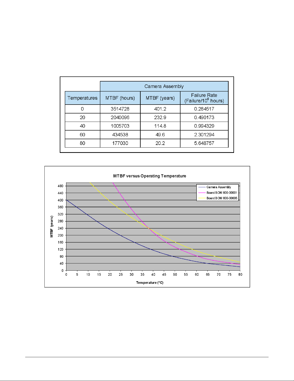
Mean Time between Failure (MTBF)
The analysis was carried out for operating temperatures varying from 0 to 80ºC. The followin g
table presents the predicted MTBF and failure rate values.
Nano Series GigE Vision Camera Genie Nano Specifications
21

Specifications: M1450, C1450
Supported Features M1450 C1450
Resolution 1456 x 1088
Sensor Sony IMX273 (1.6M)
Pixel Size 3.45 µm x 3.45 µm
Shutter type Full frame electro nic glo b al shutter function
Full Well charge 11ke (max)
Firmware option
(Field programmable)
Max. Internal Frame Rate
Full resolution
Maximum Sustained Frame Rate
Output (with TurboDrive v1) *
Maximum Sustained Frame Rate
Output (without TurboDrive)
Pixel Data Formats
Trigger to Exposure Minimum delay
(Synchronous Exposure Alignment)
Trigger to Exposure Minimum delay
(Reset Exposure Alignment)
Trigger to Exposure Start jitter (best
case with Synchronous Expo sur e
Alignment)
Trigger to Exposure Start jitter
(Reset Exposure Alignment)
Actual Exposure Time Minimum
(see “exposureTimeActual”
in Sensor Control)
Min. Time from End of Exposure to
Start of Next Exposure (second
frame)
Horizontal Line Time: 5.5 µ s
Readout Time (H line time ) x (line s in fr am e + 22) in µs
Auto-Brightness Yes , with Auto-Exposure and AGC (FPGA Gain or Sensor Gain)
Black offset control Yes
Gain Control In-sensor Analog Gain (1x to 16x)
Binning Support Yes In-FPGA (summing and average)
Decimation Support NO
Defective Pixel Replacement NO
Image Correction NO
Image Flip Support Yes, In-Sensor, Vertical and Horizontal
Multi-ROI Support Yes, in sensor up to 4 ROI (2x2) (mutually exclusive with binning)
On-Board Image Memory 90 MB
Output Dynamic Range (dB) 73.60
SNR (dB) 39.40
Standard Design Monochrome Standard Design Bayer
161 fps at 1456 x 1088 resolution
161 fps at 1456 x 1088 resolution (8-bits)
80 fps at 1456 x 1088 resolutio n (12 -bits)
75 fps at 1456 x 1088 resolutio n (8 -bits)
36 fps at 1456 x 1088 resolutio n (12 -bits)
Monochrome 8-bit
Monochrome 12-bit
2 line time (11 µs)
0 µs
Max 1 line time (0 to 5.5 µs)
0 µs
19.7 µsec in 5.5 µsec steps (i.e. 1 line time + 14. 26 µs)
18 line times – 14.26 µs (84.74 µs)
In-sensor Digital Gain (1 to 16x)
2x2, 4x4
Bayer 8-bit
Bayer 12-bit
NO
22 • Genie Nano Specifications Nano Series GigE Vision Camera
•
*TurboDrive internal limitation of 250MB/sec
Firmware Files for Models 1450
M1450
• Standard
Genie_Nano_Sony_IMX273_1.6M_Mono_STD_Firmware_10CA18.x.cbf
C1450
• Standard
Genie_Nano_Sony_IMX273_1.6M_Bayer_STD_Firmware_11CA18.x.cbf
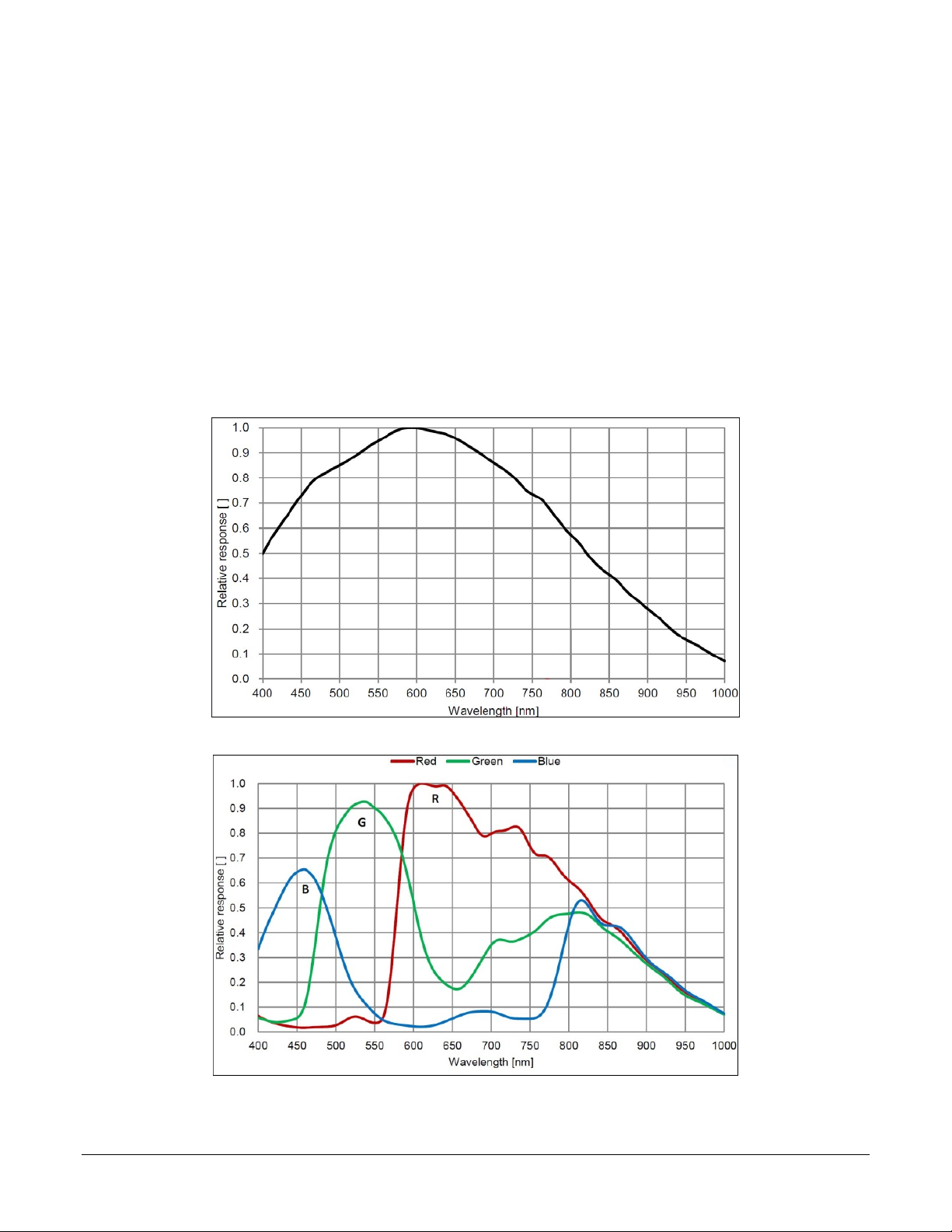
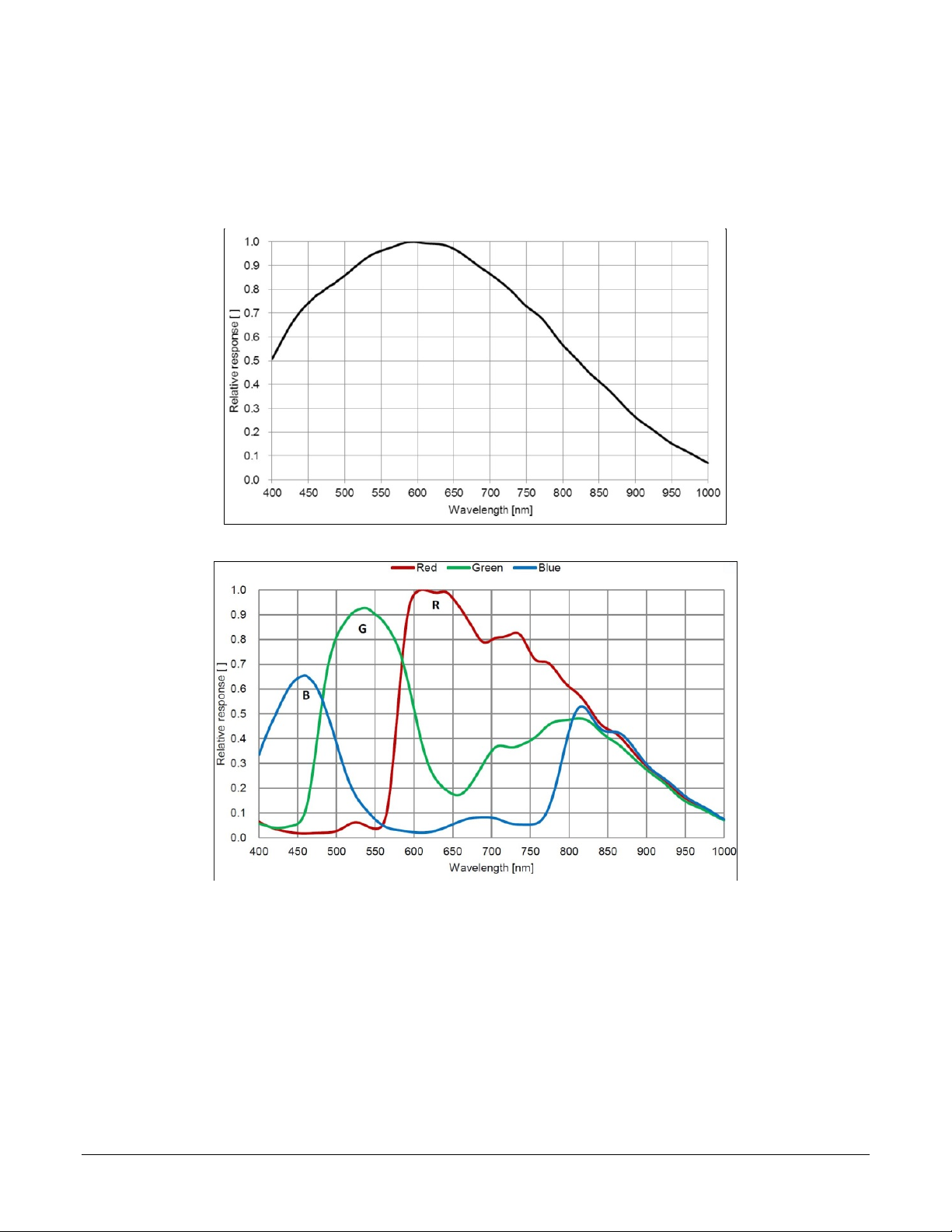
Spectral Response
Monochrome Model M1450, (Sony IMX273)
Color Model C1450, (Sony IMX273)
Nano Series GigE Vision Camera Genie Nano Specifications
23

Specifications: M1920, C1920
Supported Features M1920 C1920
Resolution 1936 x 1216
Sensor Sony IMX249 (2.3M)
Pixel Size 5.86 µm x 5.86 µm
Shutter type Full frame ele c tro nic glo b a l shutter f unc tio n
Full Well charge 32ke (max)
Firmware option
(Field programmable)
Max. Internal Frame Rate
Full resolution
Maximum Sustained Frame Rate
Output (with TurboDrive v1)
Maximum Sustained Frame Rate
Output (without TurboDrive)
Pixel Data Formats
Trigger to Exposure Minimum delay
(Synchronous Exposure Alignment)
Trigger to Exposure Minimum delay
(Reset Exposure Alignment)
Trigger to Exposure Start jitter (best
case with Synchronous Expo sur e
Alignment)
Trigger to Exposure Start jitter
(Reset Exposure Alignment)
Actual Exposure Time Minimum
(see “exposureTimeActual”
in Sensor Control)
Min. Time from End of Exposure to
Start of Next Exposure
Horizontal Line Time: 20.5 µs
Readout Time
Auto-Brightness Yes , with Auto-Exposure and AGC (FPGA Gain or Sensor Gain)
Black offset control Yes (in DN)
Gain Control In-sensor Gain (1.0x to 251x)
Binning Support Yes In-FPGA
Decimation Support No
Defective Pixel Replacement No
Image Correction No
Standard Design
Monochrome
38.8 fps (8-bit)
38.8 fps (12-bit)
38.8 fps (8-bit)
25 fps (12-bit)
Mono 8-bit
Mono 12-bit
(Horizontal Line Time) x (lines in frame +20) — in μs
In-FPGA Digital Gain (1x to 4x) in 0.007x steps
(summing and average)
2x2, 4x4
Standard Design
Bayer
38.8 fps
Bayer 8-Bit
Bayer 12-Bit
2 line time (41.5 µs)
Not supported by this sensor
Up to 1 line time
0 to 20.5 µs
Not supported by this sensor
34.23 µs (1 line time + 13.73 us)
(increment steps of 20.5 µs)
13 lines (266.5µs)
No
RGB-Output
Design
N/A
13 fps (RGBA)
19.5 fps (RGB)
26 fps (Yuv422)
38.8fps (8-bit mono)
RGBA 32-bit
RGB 24-bit
Yuv422 16-bit
Mono 8-bit
24 • Genie Nano Specifications Nano Series GigE Vision Camera

•
Image Flip Support Yes, In-Sensor, Vertical and Horizontal
Multi-ROI Support Yes, in FPGA , up to 16 ROI (mutually exclusive with binning)
On-Board Image Memory 90MB
Output Dynamic Range (dB) 72.1 dB (in 12-Bit Pixel Format)
SNR (dB) 44.3 dB (in 12-Bit Pixel Format)
Specifications: M1940, C1940
Supported Features Nano-M1940 Nano-C1940
Resolution 1936 x 1216
Sensor Sony IMX174 (2.3M)
Pixel Size 5.86 µm x 5.86 µm
Shutter type Full frame ele c tro nic glo b a l shutter f unc tio n
Full Well charge 32ke (max)
Firmware option
(Field programmable)
Max. Internal Frame Rate
Full resolution
Maximum Sustained Frame Rate
Output (with TurboDrive v1)
Maximum Sustained Frame Rate
Output (without TurboDrive)
Pixel Data Formats
Trigger to Exposure Minimum delay
(Synchronous Exposure Alignment)
Trigger to Exposure Minimum delay
(Reset Exposure Alignment)
Trigger to Exposure Start jitter (best
case with Synchronous Expo sur e
Alignment)
Trigger to Exposure Start jitter
(Reset Exposure Alignment)
Actual Exposure Time Minimum
(see “exposureTimeActual”
in Sensor Control)
Min. Time from End of Exposure to
Start of Next Exposure (second
frame)
Horizontal Line Time: 9.5 µ s
Readout Time (Horizontal Line Time) x (lines in frame +20) — in μs
Auto-Brightness Yes , with Auto-Exposure and AGC (FPGA Gain or Sensor Gain)
Black offset control Yes (in DN)
Gain Control In-sensor Gain (1.0x to 251x)
Standard Design
Monochrome
83.9 fps (8-bit)
Mono 8-bit
Mono 10-bit
In-FPGA Digital Gain (1x to 4x) in 0.007x steps
Standard Design
Bayer
83.9 fps
53 fps (10-bit)
52 fps (8-bit)
26 fps (10-bit)
Bayer 8-Bit
Bayer 10-Bit
2 line time (19 µs)
Not supported by this sensor
Up to 1 line time
0 to 9.5 µs
Not supported by this sensor
23.23 µs (1 line time + 13.73 us)
(increment steps of 9.5 µs)
13 lines (123.5µs)
RGB-Output
Design
N/A
13 fps (RGBA)
19.5 fps (RGB)
26 fps (Yuv422)
38.8fps (8-bit mono)
RGBA 32-bit
RGB 24-bit
Yuv422 16-bit
Mono 8-bit
Nano Series GigE Vision Camera Genie Nano Specifications
25

Binning Support Yes In-FPGA
(summing and average)
2x2, 4x4
Decimation Support No
Defective Pixel Replacement No
Image Correction No
Image Flip Support Yes, In-Sensor, Vertical and Horizontal
Multi-ROI Support Yes, in-sensor, up to 16 ROI (mutually exclusive with binning)
On-Board Image Memory 90MB
Output Dynamic Range (dB) 68.3 dB (in 10-Bit Pixel Format)
SNR (dB) 43.9 dB (in 10-Bit Pixel Format)
No
Notes:
* Entire Resolution includes Over-scan pixels:
• Active resolution is 1920 x 1200. The 8 + 8 additional pixels per line and 8 + 8 additional
vertical lines are available for preprocessing and/or camera mechanical alignment
operations in a system.
** Limited to the Genie Nano Architecture:
• ~250MB/sec Sustained into the TurboDrive Engine
• Additional note: This transfer was achieved using 1500 Byte Packet Size.
*** Actual Exposure Time:
• The actual internal minimum exposure may be different than what is programmed. Use the
feature “exposureTimeActual” from the Sensor C on t rol category to read back the actual
sensor exposure.
Firmware Files for 1920, 1940
The latest firmware files for all Nano models are available on the Teledyne DALSA support web site:
http://www.teledynedalsa.com/imaging/support/downloads/firmware/
The firmware files for these models are listed below. The xx denotes the current build number.
M1920
• Standard
“Genie_Nano_Sony_IMX249-2M_Mono_STD_Firmware_3CA18.xx.cbf”
C1920
• Bayer Output
“Genie_Nano_Sony_IMX249-2M_Bayer_STD_Firmware_4CA18.xx.cbf”
• RGB Output
“Genie_Nano_Sony_IMX249-2M_RGB_Output_Firmware_4CA18.xx.cbf”
M1940
• Standard
“Genie_Nano_Sony_IMX174-2M_Mono_STD_Firmware_1CA18.xx.cbf”
C1940
• Bayer Output
“Genie_Nano_Sony_IMX174-2M_Bayer_STD_Firmware_2CA18.xx.cbf”
• RGB Output
“Genie_Nano_Sony_IMX174-2M_RGB_Output_Firmware_4CA18.xx.cbf”
26 • Genie Nano Specifications Nano Series GigE Vision Camera
•
Spectral Response
Monochrome Models M194x & M192x, (Sony IMX174 & IMX249)
Measured Fill-Factor x Quantum Efficiency (FF x QE)
Color Models C194x & C192x, (Sony IMX174 & IMX249)
Measured Fill-Factor x Quantum Efficiency (FF x QE)
Nano Series GigE Vision Camera Genie Nano Specifications
27
Specifications: M2020, C2020
Supported Features Nano-M2020 Nano-C2020
Resolution 2064 x 1544
Sensor Sony IMX265 (3.2M)
Pixel Size 3.45 µm x 3.45 µm
Shutter type Full frame electro nic glo b al shutter function
Full Well charge 11ke (max)
Firmware option
(Field programmable)
Max. Internal Frame Rate
Full resolution
Maximum Sustained Frame Rate
Output (with TurboDrive v1) *
Maximum Sustained Frame Rate
Output (without TurboDrive)
Pixel Data Formats
Trigger to Exposure Minimum delay
(Synchronous Exposure Alignment)
Trigger to Exposure Minimum delay
(Reset Exposure Alignment)
Trigger to Exposure Start jitter (best
case with Synchronous Expo sur e
Alignment)
Trigger to Exposure Start jitter
(Reset Exposure Alignment)
Actual Exposure Time Minimum
(see “exposureTimeActual”
in Sensor Control)
Min. Time from End of Exposure to
Start of Next Exposure (second
frame)
Horizontal Line Time: 11.9 µs
Readout Time (Horizontal Line Time) x (lines in frame +17) — in μs
Auto-Brightness Yes , with Auto-Exposure and AGC (FPGA Gain or Sensor Gain)
Black offset control Yes (in DN)
Gain Control In-sensor Gain (1.0x to 251x)
Binning Support Yes In-FPGA (summing and average)
Decimation Support No
Defective Pixel Replacement No
Image Correction No
Image Flip Support Yes, In-Sensor, Vertical and Horizontal
Multi-ROI Support Yes, in FPGA, up to 16 ROI (mutually ex c lus iv e wi th b inning )
Standard Design
Monochrome
53.3 fps (8-bit)
41.0 fps (12-bit)
38 fps (8-bit)
18 fps (12-bit)
Mono 8-bit
Mono 12-bit
2 line time (23.8 µs)
Up to 1 line time
0 to 11.9 µs
25.65µs (1 line time + 13.73 us)
(increment steps of 11.9µs)
8 lines (81.6 µs)
In-FPGA Digital Gain (1x to 4x) in 0.007x step
2x2, 4x4
Standard Design
Bayer
53.3 fps
Bayer 8-Bit
Bayer 12-Bit
0 µs
0 µs
RGB-Output
Design
9 fps (RGBA)
13.5 fps (RGB)
18 fps (Yuv422)
38 fps (mono8)
RGBA 32-bit
RGB 24-bit
Yuv422 16-bit
Mono 8-bit
No
N/A
28 • Genie Nano Specifications Nano Series GigE Vision Camera

•
On-Board Image Memory 90MB
Output Dynamic Range (dB) 76.4 dB (in 12-Bit Pixel Format)
SNR (dB) 39.6 dB (in 12-Bit Pixel Format)
* Limited to the Genie Nano Architecture:
~250MB/sec Sustained into the TurboDrive Engine achieved using 1500 Byte Packet Size
Firmware Files for Models 2020
The latest firmware files for all Nano models are available on the Teledyne DALSA support web site:
http://www.teledynedalsa.com/imaging/support/downloads/firmware/
The firmware files for these models are listed below. The xx denotes the current build number.
M2020
• Standard
“Genie_Nano_Sony_IMX264-265_3.2M-5.1M_Mono_STD_Firmware_9CA18.xx.cbf”
C2020
• Bayer Output
“Genie_Nano_Sony_IMX264-265_3.2M-5.1M_Bayer_STD_Firmware_ACA18.xx.cbf”
• RGB Output
“Genie_Nano_Sony_IMX264-265_3.2M-5.1M_RGB_Firmware_ACA18.xx.cbf”
Specifications: M2050
Supported Features Nano-M2050
Resolution 2064 x 1544
Sensor Sony IMX252 (3.2M)
Pixel Size 3.45 µm x 3.45 µm
Shutter type Full frame ele c tro nic glo b a l shutter f unc tio n
Firmware option
(Field programmable)
Full Well charge; dependent on
Firmware Design Loaded
Sensitivity to Saturation 4x 1x
Max. Internal Frame Rate
Full resolution
Maximum Sustained Frame Rate
Output (with TurboDrive v1) *
Maximum Sustained Frame Rate
Output (without TurboDrive)
Pixel Data Formats Mono 8-bit
Trigger to Exposure Minimum delay
(Synchronous Exposure Alignment)
Trigger to Exposure Minimum delay
(Reset Exposure Alignment)
Trigger to Exposure Start jitter (best
case with Synchronous Expo sur e
Alignment)
High Sensitivity Design Standard Design
2750e- (max) 11ke (max)
143 fps 11 6 fps
82 fps (8-bit)
38 fps (8-bit)
2 line time
(8.8 µs)
0 µs
Max 1 line
(0 to 4.4µs)
2 line time
(10.8 µs)
Max 1 line
(0 to 5.4µs)
Nano Series GigE Vision Camera Genie Nano Specifications
29

Trigger to Exposure Start jitter
(Reset Exposure Alignment)
Actual Exposure Time Minimum
(see “exposureTimeActual”
in Sensor Control)
Min. Time from End of Exposure to
Start of Next Exposure
Horizontal Line Time: 4.4µs 5.4µs
Readout Time
Auto-Brightness Yes , with Auto-Exposure and AGC (FPGA Gain or Sensor Gain)
Black offset control Yes (in DN)
Gain Control In-sensor Gain (1.0x to 251x)
Binning Support Yes In-FPGA (summing and average)
Decimation Support No
Defective Pixel Replacement No
Image Correction No
Image Flip Support Yes, In-Sensor, Vertical and Horizontal
Multi-ROI Support Yes, In-Sensor, up to 16 ROI (mutually exclusive with in-sensor binning)
On-Board Image Memory 90MB
Output Dynamic Range (dB) 56.7 75.4 dB (in 8-Bit Pixel Format)
SNR (dB) 33.01 39.6 dB (in 8-Bit Pixel Format)
18.1µs (1 line time + 13.73 us)
(increment of 4.4µs steps)
10 lines–13.73µs
(30.3 µs)
(H Line Time) x (lines in frame +23) — in μs
In-FPGA Digital Gain (1x to 4x) in 0.007x steps
0 µs
19.1µs (1 line time + 13.73 us)
(increment of 5.4µs steps)
10 lines–13.73µs
(40.4 µs)
2x2, 4x4
* Limited to the Genie Nano Architecture:
~250MB/sec Sustained into the TurboDrive Engine achieved using 1500 Byte Packet Size
Firmware Files for Model M2050
The latest firmware files for all Nano models are available on the Teledyne DALSA support web site:
http://www.teledynedalsa.com/imaging/support/downloads/firmware/
The firmware files for this model are listed below. The xx denotes the current build number.
M2050
• Standard
“Genie_Nano_Sony_IMX25x_3.2M-5.1M-9M-12M _M ono_STD_Firmware_7CA18.xx.cbf”
• High Sensitivity
“Genie_Nano_Sony_IMX25x_3.2M-5.1M-9M-12M_Mono_HSD_Firmware_7CA18.xx.cbf”
30 • Genie Nano Specifications Nano Series GigE Vision Camera

•
Specifications: C2050
Supported Features Nano-C2050
Resolution 2064 x 1544
Sensor Sony IMX252 (3.2M)
Pixel Size 3.45 µm x 3.45 µm
Shutter type Full frame electronic glo b al shutter f unc ti o n
Firmware option
(Field programmable)
Full Well charge; dependent on
Firmware Design Loaded
Sensitivity to Saturation 4x 1x
Max. Internal Frame Rate
Full resolution
Maximum Sustained Frame Rate
Output (with TurboDrive v1) *
Maximum Sustained Frame Rate
Output (without TurboDrive)
Pixel Data Formats Bayer 8-Bit Bayer 8-Bit
Trigger to Exposure Minimum delay
(Synchronous Exposure Alignment)
Trigger to Exposure Minimum delay
(Reset Exposure Alignment)
Trigger to Exposure Start jitter (best
case with Synchronous Exposure
Alignment)
Trigger to Exposure Start jitter
(Reset Exposure Alignment)
Actual Exposure Time Minimum
(see “exposureTimeActual”
in Sensor Control)
Min. Time from End of Exposure to
Start of Next Exposure
Horizontal Line Time: 4.4µs 5.4µs
Readout Time
Auto-Brightness Yes , with Auto-Exposure and AGC (FPGA Gain or Sensor Gain)
Black offset control Yes (in DN)
Gain Control In-sensor Gain (1.0x to 251x)
Binning Support No
Decimation Support No
Defective Pixel Replacement No
Image Correction No
High Sensitivity
Design (Bayer)
2750e- (max) 11ke (max)
143 fps 116 fps
82 fps (8-bit) 82 fps (8-bit) N/A
38 fps (8-bit) 38 fps (8-bit)
2 line time
(8.8 µs)
Max 1 line
(0 to 4.4µs)
18.1µs (1 line time+13.73 us)
(increment of 4.4µs steps)
10 lines–13.73µs
(30.3 µs)
(H Line Time) x (lines in frame +23) — in μs
In-FPGA Digital Gain (1x to 4x) in 0.007x steps
Standard Design
(Bayer)
2 line time
(10.8 µs)
0 µs
Max 1 line
(0 to 5.4µs)
0 µs
19.1µs (1 line time + 13.73 us)
(increment of 5.4µs steps)
10 lines–13.73µs
(40.4 µs)
RGB-Output
Standard Design
9.7 fps (RGBA)
14.5 fps (RGB)
19 fps (Yuv422)
38 fps (mono8)
RGBA 32-bit
RGB 24-bit
Yuv422 16-bit
Mono 8-bit
Nano Series GigE Vision Camera Genie Nano Specifications
31

Image Flip Support Yes, In-Sensor, Vertical and Horizontal
Multi-ROI Support Yes, In-Sensor, up to 16 RO I ( mutually exclusive with in-sensor binning)
On-Board Image Memory 90MB
Output Dynamic Range (dB) 56.7 75.4 dB (in 8-Bit Pixel Format)
SNR (dB) 33.01 39.6 dB (in 8-Bit Pixel Format)
* Limited to the Genie Nano Architecture:
~250MB/sec Sustained into the TurboDrive Engine achieved using 1500 Byte Packet Size
Firmware Files for Model C2050
The latest firmware files for all Nano models are available on the Teledyne DALSA support web site:
http://www.teledynedalsa.com/imaging/support/downloads/firmware/
The firmware files for this model are listed below. The xx denotes the current build number.
C2050
• Bayer Output
“Genie_Nano_Sony_IMX25x_3.2M-5.1M-9M-12M _Bayer_STD_Firmware_8CA18.xx.cbf
• High Sensitivity Bayer O utput
“Genie_Nano_Sony_IMX25x_3.2M-5.1M-9M-12M _Bayer_HSD_Firmware_8CA18.xx.cbf”
• RGB Output
“Genie_Nano_Sony_IMX25x_3.2M-5.1M-9M-12M _R G B_Output_Firmware_8CA18.xx.cbf”
32 • Genie Nano Specifications Nano Series GigE Vision Camera
•
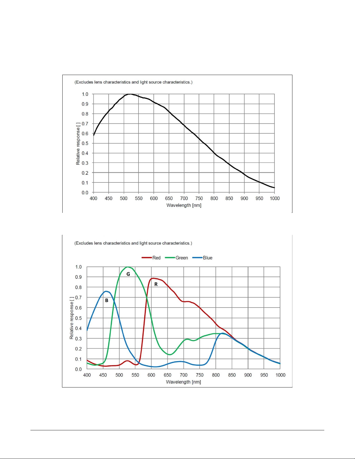
Spectral Responses
The response curves describe the sensor, excluding lens and light source characteristics.
Models M2020, M2050
Models C2020, C2050
Nano Series GigE Vision Camera Genie Nano Specifications
33

Specifications: M2420, C2420
Supported Features Nano-M2420 Nano-C2420
Resolution 2464x 2056
Sensor Sony IMX264 ( 5.1M)
Pixel Size 3.45 µm x 3.45 µm
Shutter type Full frame electronic glob al shutter f unc tion
Full Well charge 11ke (max)
Firmware option
(Field programmable)
Max. Internal Frame Rate
Full resolution
Maximum Sustained Frame Rate Output
(with TurboDrive v1) *
Maximum Sustained Frame Rate Output
(without TurboDrive)
Pixel Data Formats
Trigger to Exposure Minimum delay
(Synchronous Exposure Alignment)
Trigger to Exposure Minimum delay
(Reset Exposure Alignment)
Trigger to Exposure Start jitter (best case
with Synchronous Exposure Alignment)
Trigger to Exposure Start jitter
(Reset Exposure Alignment)
Actual Exposure Time Minimum
(see “exposureTimeActual”
in Sensor Control)
Min. Time from End of Exposure to Start of
Next Exposure (second frame)
Horizontal Line Time: 13.9 µs
Readout Time (Horizontal Line Time) x (lines in frame +17) — in μs
Auto-Brightness Yes , with Auto-Exposure and AGC (FPGA Gain or Sensor Gain)
Black offset control Yes (in DN)
Gain Control In-sensor Gain (1.0x to 251x)
Binning Support Yes In-FPGA
Decimation Support No
Defective Pixel Replacement No
Image Correction No
Image Flip Support Yes, In-Sensor, Vertical and Horizontal
Multi-ROI Support Yes, in FPGA, up to 16 ROI (mutually exclusive with binning)
On-Board Image Memory 90MB
Standard Design
Monochrome
34.4 fps (8-bit)
26.1 fps (12-bit)
22.5 fps (8-bit)
11 fps (12-bit)
Mono 8-bit
Mono 12-bit
27.65µs (1 line time + 13.73 us)
In-FPGA Digital Gain (1x to 4x) in 0.007x step
(summing and average)
2x2, 4x4
Standard Design
Bayer
34.4 fps
Bayer 8-Bit
Bayer 12-Bit
2 line time (27.8 µs)
0 µs
Up to 1 line time
0 to 13.9 µs
0 µs
(increment steps of 13.9 µs)
8 lines (97.6 µs)
No
RGB-Output
Design
N/A
5.5 fps (RGBA)
8 fps (RGB)
11 fps (Yuv422)
22 fps (mono8)
RGBA 32-bit
RGB 24-bit
Yuv422 16-bit
Mono 8-bit
34 • Genie Nano Specifications Nano Series GigE Vision Camera

•
Output Dynamic Range (dB) 76.8 dB (in 12-Bit Pixel Format)
SNR (dB) 39.5 dB (in 12-Bit Pixel Format)
* Limited to the Genie Nano Architecture:
~250MB/sec Sustained into the TurboDrive Engine achieved using 1500 Byte Packet Size
Firmware Files for Models 2420
The latest firmware files for all Nano models are available on the Teledyne DALSA support web site:
http://www.teledynedalsa.com/imaging/support/downloads/firmware/
The firmware files for these models are listed below. The xx denotes the current build number.
M2420
• Standard
“Genie_Nano_Sony_IMX264-265_3.2M-5.1M_Mono_STD_Firmware_9CA18.xx.cbf”
C2420
• Bayer Output
“Genie_Nano_Sony_IMX264-265_3.2M-5.1M_Bayer_STD_Firmware_ACA18.xx.cbf”
• RGB Output
“Genie_Nano_Sony_IMX264-265_3.2M-5.1M_RGB_Firmware_ACA18.xx.cbf”
Specifications: M2450
Supported Features M2450
Resolution 2464 x 2056
Sensor Sony IMX250 (5.1M)
Pixel Size 3.45 µm x 3.45 µm
Shutter type Full frame electro nic glo b al shutter function
Firmware option
(Field programmable)
Full Well charge; dependent on
Firmware Design Loaded
Sensitivity to Saturation 4x 1x
Max. Internal Frame Rate
Full resolution
Maximum Sustained Frame Rate
Output (with TurboDrive v1)*
Maximum Sustained Frame Rate
Output (without TurboDrive)
Pixel Data Formats Mono 8-bit
Trigger to Exposure Minimum delay
(Synchronous Exposure Alignment)
Trigger to Exposure Minimum delay
(Reset Exposure Alignment)
Trigger to Exposure Start jitter (best
case with Synchronous Expo sur e
Alignment)
Trigger to Exposure Start jitter
(Reset Exposure Alignment)
High Sensitivity
Design
2750e- (max) 11ke (max)
93 fps 76 fps
49 fps (8-bit)
22 fps (8-bit)
2 line time
(10.22 µs)
0 µs
Max 1 line
(0 to 5.11µs)
0 µs
Standard Design
(Mono)
2 line time
(12.5 µs)
Max 1 line
(0 to 6.25µs)
Nano Series GigE Vision Camera Genie Nano Specifications
35

Actual Exposure Time Minimum
(see “exposureTimeActual”
in Sensor Control)
Min. Time from End of Exposure to
Start of Next Exposure
Horizontal Line Time: 5.11µs 6.2µs
Readout Time (H Line T ime ) x (lines in frame +23) — in μs
Auto-Brightness Yes , with Auto-Exposure and AGC (FPGA Gain or Sensor Gain)
Black offset control Yes (in DN)
Gain Control In-sensor Analog Gain (1.0x to 251x )
Binning Support Yes In-FPGA
Decimation Support No
Defective Pixel Replacement No
Image Correction no
Image Flip Support Yes, In-Sensor, Vertical and Horizontal
Multi-ROI Support Yes, In-Sensor, up to 16 ROI (mutually exclusive with in-sensor binning)
On-Board Image Memory 90MB
Output Dynamic Range (dB) 56.7 75.4 dB (in 8-Bit Pixel Format)
SNR (dB) 33.01 39.6 dB (in 8-Bit Pixel Format)
18.8µs (1 line time + 13.73 us)
(increment of 5.11µs steps)
10 lines–13.73µs
(37.3 µs)
(summing and average)
19.9µs (1 line time + 13.73 us)
(increment of 6.2µs steps)
10 lines–13.73µs
(48.8 µs)
2x2, 4x4
* Limited to the Genie Nano Architecture:
~250MB/sec Sustained into the TurboDrive Engine achieved using 1500 Byte Packet Size
Firmware Files for Model M2450
The latest firmware files for all Nano models are available on the Teledyne DALSA support web site:
http://www.teledynedalsa.com/imaging/support/downloads/firmware/
The firmware files for this model are listed below. The xx denotes the current build number.
M2450
• Standard
“Genie_Nano_Sony_IMX25x_3.2M-5.1M-9M-12M _M ono_STD_Firmware_7CA18.xx.cbf”
• High Sensitivity
“Genie_Nano_Sony_IMX25x_3.2M-5.1M-9M-12M_Mono_HSD_Firmware_7CA18.xx.cbf”
36 • Genie Nano Specifications Nano Series GigE Vision Camera

•
Specifications: C2450
Supported Features C2450
Resolution 2464 x 2056
Sensor Sony IMX250 (5.1M)
Pixel Size 3.45 µm x 3.45 µm
Shutter type Full frame electronic glo b al shutter f unc ti o n
Firmware option
(Field programmable)
Full Well charge; dependent on
Firmware Design Loaded
Sensitivity to Saturation 4x 1x
Max. Internal Frame Rate
Full resolution
Maximum Sustained Frame Rate
Output (with TurboDrive v1)*
Maximum Sustained Frame Rate
Output (without TurboDrive)
Pixel Data Formats Bayer 8-Bit Bayer 8-Bit
Trigger to Exposure Minimum delay
(Synchronous Exposure Alignment)
Trigger to Exposure Minimum delay
(Reset Exposure Alignment)
Trigger to Exposure Start jitter (best
case with Synchronous Expo sur e
Alignment)
Trigger to Exposure Start jitter
(Reset Exposure Alignment)
Actual Exposure Time Minimum
(see “exposureTimeActual”
in Sensor Control)
Min. Time from End of Exposure to
Start of Next Exposure
Horizontal Line Time: 5.11µs 6.2µs
Readout Time (H Line Time ) x (lines in frame +23) — in μs
Auto-Brightness Yes , with Auto-Exposure and AGC (FPGA Gain or Sensor Gain)
Black offset control Yes (in DN)
Gain Control In-sensor Analog Gain (1.0x to 251x)
Binning Support No
Decimation Support No
Defective Pixel Replacement No
Image Correction no
Image Flip Support Yes, In-Sensor, Vertical and Horizontal
High Sensitivity Design
(Bayer)
2750e- (max) 11ke (max)
93 fps 76 fps
49 fps (8-bit) 49 fps (8-bit) N/A
22 fps (8-bit) 22 fps (8-bit)
2 line time
(10.22 µs)
Max 1 line
(0 to 5.11µs)
18.8µs (1 line time+13.73 us)
(increment of 5.11µs steps)
10 lines–13.73µs
(37.3 µs)
Standard Design
(Bayer)
2 line time
(12.5 µs)
0 µs
Max 1 line
(0 to 6.25µs)
0 µs
19.9µs (1 line time + 13.73 us)
(increment of 6.2µs steps)
10 lines–13.73µs
(48.8 µs)
RGB-Output
Design
5.5 fps (RGBA)
8.7 fps (RGB)
11 fps (Yuv422)
22 fps (mono8)
RGBA 32-bit
RGB 24-bit
Yuv422 16-bit
Mono 8-bit
Nano Series GigE Vision Camera Genie Nano Specifications
37

Multi-ROI Support Yes, In-Sensor, up to 16 ROI ( mutually exclusive with in-sensor binning)
On-Board Image Memory 90MB
Output Dynamic Range (dB) 56.7 75.4 dB (in 8-Bit Pixel Format)
SNR (dB) 33.01 39.6 dB (in 8-Bit Pixel Format)
* Limited to the Genie Nano Architecture:
~250MB/sec Sustained into the TurboDrive Engine achieved using 1500 Byte Packet Size
Firmware Files for Model C2450
The latest firmware files for all Nano models are available on the Teledyne DALSA support web site:
http://www.teledynedalsa.com/imaging/support/downloads/firmware/
The firmware files for this model are listed below. The xx denotes the current build number.
C2450
• Bayer Output
“Genie_Nano_Sony_IMX25x_3.2M-5.1M-9M-12M _Bayer_STD_Firmware_8CA18.xx.cbf
• High Sensitivity Bayer Output
“Genie_Nano_Sony_IMX25x_3.2M-5.1M-9M-12M _Bayer_HSD_Firmware_8CA18.xx.cbf”
• RGB Output
“Genie_Nano_Sony_IMX25x_3.2M-5.1M-9M-12M _R G B_Output_Firmware_8CA18.xx.cbf”
38 • Genie Nano Specifications Nano Series GigE Vision Camera

•
Spectral Responses
The response curves describe the sensor, excluding lens and light source characteristics.
Models M2450
Models C2450
Nano Series GigE Vision Camera Genie Nano Specifications
39

Specifications: M4060
Sensitivity to Saturation
4x
1x
Supported Features M4060
Resolution 4112 x 2176
Sensor Sony IMX255 (8.9M)
Pixel Size 3.45 µm x 3.45 µm
Shutter type Full frame electro nic glo b al shutter function
Firmware option
(Field programmable)
Full Well charge; dependent on
Firmware Design Loaded
High Sensitivity Design Firmware Standard Design Firmware
2750e- (max) 11ke (max)
Max. Internal Frame Rate
Full resolution
Maximum Sustained Frame Rate
Output (with TurboDrive v1)*
Maximum Sustained Frame Rate
Output (without TurboDrive)
Pixel Data Formats Mono 8-bit
Trigger to Exposure Minimum delay
(Synchronous Exposure Alignment)
Trigger to Exposure Minimum delay
(Reset Exposure Alignment)
Trigger to Exposure Start jitter (best
case with Synchronous Expo sur e
Alignment)
Trigger to Exposure Start jitter
(Reset Exposure Alignment)
Actual Exposure Time Minimum
(see “exposureTimeActual”
in Sensor Control)
Min. Time from End of Exposure to
Start of Next Exposure
Horizontal Line Time:
Normal operation
(with In-Sensor Binning enable)
Readout Time (H Line Time) x (lines in frame +39) in μs
Auto-Brightness Yes , with Auto-Exposure and AGC (FPGA Gain or Sensor Gain)
Black offset control Yes (in DN)
Gain Control In-sensor Analog Gain (1.0x to 251x )
Binning Support Yes, In-sensor 2x2 (averaging)
Decimation Support No
Defective Pixel Replacement Yes , up to 512 pixel position
Image Correction no
Image Flip Support Yes, In-Sensor, Vertical and Horizontal
Multi-ROI Support Yes, In-Sensor, up to 16 ROI (mutually exclusive with in-sensor binning)
On-Board Image Memory 220MB
Output Dynamic Range (dB) 56.43 76.46 dB (in 8-Bit Pixel Format)
22µs (1 line time + 14.26 us)
(increment of 7.89µs steps)
56 fps 46 fps
28 fps (8-bit)
13 fps (8-bit)
2 line time (15.8µs) 2 line time (19.5µs)
0 µs
Max 1 line
0 to 7.89µs
0 µs
24µs (1 line time + 14.26 us)
(increment of 9.72µs steps)
16 lines –14.26µs
(112µs)
7.89µs
(4.95µs)
Yes In-FPGA (summing and average, 2x2, 4x4 )
Max 1 line
0 to 9.72µs
16 lines – 14.26µs
(141.3µs)
9.72µs
(5.27µs)
40 • Genie Nano Specifications Nano Series GigE Vision Camera

•
Sensitivity to Saturation
4x
1x
SNR (dB) 33.01 39.38 dB (in 8-Bit Pixel Format)
* Limited to the Genie Nano Architecture:
~250MB/sec Sustained into the TurboDr ive Eng ine ac hie ved using 1500 Byte Packet Size
Firmware Files for Model M4060
The latest firmware files for all Nano models are available on the Teledyne DALSA support web site:
http://www.teledynedalsa.com/imaging/support/downloads/firmware/
The firmware files for this model are listed below. The xx denotes the current build number.
M4060
• Standard
“Genie_Nano_Sony_IMX25x_3.2M-5.1M-9M-12M _Mono_STD_Firmware_7CA18.xx.cbf”
• High Sensitivity
“Genie_Nano_Sony_IMX25x_3.2M-5.1M-9M-12M_Mono_HSD_Firmware_7CA18.xx.cbf”
Specifications: C4060
Supported Features C4060
Resolution 4112 x 2176
Sensor Sony IMX255 (8.9M)
Pixel Size 3.45 µm x 3.45 µm
Shutter type Full frame electro nic glo b al shutter function
Firmware option
(Field programmable)
Full Well charge; dependent on
Firmware Desi g n Loaded
High Sensitivity
Design (Bayer)
2750e- (max) 11ke (max)
Standard Design
(Bayer)
RGB-Output
Design
Max. Internal Frame Rate
Full resolution
Maximum Sustained Frame Rate
Output (with TurboDrive v1)*
Maximum Sustained Frame Rate
Output (without TurboDrive)
Pixel Data Formats Bayer 8-Bit Bayer 8-Bit
Trigger to Exposure Minimum delay
(Synchronous Exposure Alignment)
Trigger to Exposure Minimum delay
(Reset Exposure Alignment)
Trigger to Exposure Start jitter (best
case with Synchronous Expo sur e
Alignment)
Trigger to Exposure Start jitter
(Reset Exposure Alignment)
56 fps 46 fps
28 fps (8-bit) N/A
13 fps (8-bit)
2 line time (15.8µs) 2 line time (19.5µs)
0 µs
Max 1 line
0 to 7.89µs
0 µs
3.2fps (RGBA)
4.3 fps (RGB)
6.5 fps (Yuv422)
13 fps (mono8)
RGBA 32-bit
RGB 24-bit
Yuv422 16-bit
Mono 8-bit
Max 1 line
0 to 9.72µs
Nano Series GigE Vision Camera Genie Nano Specifications
41

Actual Exposure Time Minimum
(see “exposureTimeActual”
in Sensor Control)
Min. Time from End of Exposure to
Start of Next Exposure
Horizontal Line Time:
Normal operation
(with In-Sensor Binning enable)
Readout Time (H Line Time) x (lines in frame +39) in μs
Auto-Brightness Yes , with Auto-Exposure and AGC (FPGA Gain or Sensor Gain)
Black offset control Yes (in DN)
Gain Control In-sensor Analog Gain (1.0x to 251x )
Binning Support No
Decimation Support No
Defective Pixel Replacement Yes , up to 512 pixel position
Image Correction no
Image Flip Support Yes, In-Sensor, Vertical and Horizontal
Multi-ROI Support Yes, In-Sensor, up to 16 ROI (mutually exclusive with in-sensor binning)
On-Board Imag e Memory 220MB
Output Dynamic Range (dB) 56.43 76.46 dB (in 8-Bit Pixel Format)
SNR (dB) 33.01 39.38 dB (in 8-Bit Pixel Format)
* Limited to the Genie Nano Architecture:
~250MB/sec Sustained into the TurboDrive Engine achieved using 1500 Byte Packet Size
(1 line time + 14.26 us)
22µs
(in 7.89µs steps)
16 lines –14.26µs
(112µs)
7.89µs
(4.95µs)
24µs (1 line time + 14.26 us)
(in 9.72µs steps)
16 lines – 14.26µs
(141.3µs)
9.72µs
(5.27µs)
Firmware Files for Model C4060
The latest firmware files for all Nano models are available on the Teledyne DALSA support web site:
http://www.teledynedalsa.com/imaging/support/downloads/firmware/
The firmware files for this model are listed below. The xx denotes the current build number.
C4060
• Bayer Output
“Genie_Nano_Sony_IMX25x_3.2M-5.1M-9M-12M _Bayer_STD_Firmware_8CA18.xx.cbf”
• High Sensitivity Bayer Output
“Genie_Nano_Sony_IMX25x_3.2M-5.1M-9M-12M _Bayer_HSD_Firmware_8CA1 8. xx.cbf”
• RGB Output
“Genie_Nano_Sony_IMX25x_3.2M-5.1M-9M-12M _R G B_Firmware_8CA18.xx .cbf”
42 • Genie Nano Specifications Nano Series GigE Vision Camera

•
Specifications: M4040
Supported Features M4040
Resolution 4112 x 3008
Sensor Sony IMX253 ( 12M)
Pixel Size 3.45 µm x 3.45 µm
Shutter type Full frame ele c tro nic glo b a l shutter f unc tio n
Firmware option
(Field programmable)
Full Well charge; dependent on
Firmware Design Loaded
Sensitivity to Saturation 4x 1x
Max. Internal Frame Rate
Full resolution
Maximum Sustained Frame Rate
Output (with TurboDrive v1) *
Maximum Sustained Frame Rate
Output (without TurboDrive)
Pixel Data Formats Mono 8-bit
Trigger to Exposure Minimum delay
(Synchronous Exposure Alignment)
Trigger to Exposure Minimum delay
(Reset Exposure Alignment)
Trigger to Exposure Start jitter (best
case with Synchronous Expo sur e
Alignment)
Trigger to Exposure Start jitter
(Reset Exposure Alignment)
Actual Exposure Time Minimum
(see “exposureTimeActual”
in Sensor Control)
Min. Time from End of Exposure to
Start of Next Exposure
Horizontal Line Time:
Normal operation
(with In-Sensor Binning enabled)
Readout Time (H Line Time) x (lines in frame +39) in μs
Auto-Brightness Yes , with Auto-Exposure and AGC (FPGA Gain or Sensor Gain)
Black offset control Yes (in DN)
Gain Control In-sensor Analog Ga in (1.0x to 251x)
Binning Support Yes In-FPGA (summing and ave rage, 2x2, 4x4 )
Decimation Support No
Defective Pixel Replacement Yes , up to 512 pixel position
Image Correction no
Image Flip Support Yes, In-Sensor, Vertical and Horizontal
Multi-ROI Support Yes, In-Sensor, up to 16 ROI (mutually exclusive with in-sensor binning)
High Sensitivity
Design
2750e- (max) 11ke (max)
41 fps 33 fps
21 fps (8-bit)
9.7 fps (8-bit)
2 line time (15.8µs) 2 line time (19.5µs)
0 µs
Max 1 line
0 to 7.89µs
0 µs
22µs (1 line time + 14.26 us)
(increment of 7.89µs steps)
16 lines –14.26µs
(112µs)
7.89µs
(4.95µs)
Yes, In-sensor 2x2 (averaging)
Standard Design
(Mono)
Max 1 line
0 to 9.72µs
24µs (1 line time + 14.26 us)
(increment of 9.72µs steps)
16 lines – 14.26µs
(141.3µs)
9.72µs
(5.27µs)
Nano Series GigE Vision Camera Genie Nano Specifications
43

On-Board Image Memory 220MB
Output Dynamic Range (dB) 56.43 76.46 dB (in 8-Bit Pixel Format)
SNR (dB) 32.01 39.50 dB (in 8-Bit Pixel Format)
* Limited to the Genie Nano Architecture:
~250MB/sec Sustained into the TurboDrive Engine achieved using 1500 Byte Packet Size
Firmware Files for Model M4040
The latest firmware files for all Nano models are available on the Teledyne DALSA support web site:
http://www.teledynedalsa.com/imaging/support/downloads/firmware/
The firmware files for this model are listed below. The xx denotes the current build number.
M4040
• Standard
“Genie_Nano_Sony_IMX25x_3.2M-5.1M-9M-12M _M ono_STD_Firmware_7CA18.xx.cbf”
• High Sensitivity
“Genie_Nano_Sony_IMX25x_3.2M-5.1M-9M-12M_Mono_HSD_Firmware_7CA18.xx.cbf”
44 • Genie Nano Specifications Nano Series GigE Vision Camera

•
Specifications: C4040
Supported Features C4040
Resolution 4112 x 3008
Sensor Sony IMX253 ( 12M)
Pixel Size 3.45 µm x 3.45 µm
Shutter type Full frame ele c tro nic glo b a l shutter f unc tio n
Firmware option
(Field programmable)
Full Well charge; dependent on
Firmware Design Loaded
Sensitivity to Saturation 4x 1x
Max. Internal Frame Rate
Full resolution
Maximum Sustained Frame Rate
Output (with TurboDrive v1) *
Maximum Sustained Frame Rate
Output (without TurboDrive)
Pixel Data Formats Bayer 8-bit Bayer 8-Bit
Trigger to Exposure Minimum delay
(Synchronous Exposure Alignment)
Trigger to Exposure Minimum delay
(Reset Exposure Alignment)
Trigger to Exposure Start jitter (best
case with Synchronous Expo sur e
Alignment)
Trigger to Exposure Start jitter
(Reset Exposure Alignment)
Actual Exposure Time Minimum
(see “exposureTimeActual”
in Sensor Control)
Min. Time from End of Exposure to
Start of Next Exposure
Horizontal Line Time:
Normal operation
(with In-Sensor Binning enable)
Readout Time (H Line Time) x (lines in frame +39) in μs
Auto-Brightness Yes , with Auto-Exposure and AGC (FPGA Gain or Sensor Gain)
Black offset control Yes (in DN)
Gain Control In-sensor Analog Ga in (1.0x to 251x)
Binning Support No
Decimation Support No
Defective Pixel Replacement Yes , up to 512 pixel position
High Sensitivity Design
(Bayer)
2750e- (max) 11ke (max)
41 fps 33 fps
21 fps (8-bit) N/A
9.7 fps (8-bit)
2 line time (15.8µs) 2 line time (19.5µs)
Max 1 line
0 to 7.89µs
22µs
(1 line time + 14.26 us)
(increment of 7.89µs
steps)
16 lines –14.26µs
(112µs)
7.89µs
(4.95µs)
Standard Design
(Bayer)
0 µs
Max 1 line
0 to 9.72µs
0 µs
24µs (1 line time + 14.26 us)
(increment of 9.72µs steps)
16 lines – 14.26µs
(141.3µs)
9.72µs
(5.27µs)
RGB-Output
Design
2.4fps (RGBA)
3.2fps (RGB)
4.3fps (Yuv422)
9.7fps (mono8)
RGBA 32-bit
RGB 24-bit
Yuv422 16-bit
Mono 8-bit
Nano Series GigE Vision Camera Genie Nano Specifications
45

Image Correction no
Image Flip Support Yes, In-Sensor, Vertical and Horizontal
Multi-ROI Support Yes, In-Sensor, up to 16 ROI (mutually exclusive with in-sensor binning)
On-Board Image Memory 220MB
Output Dynamic Range (dB) 56.43 76.46 dB (in 8-Bit Pixel Format)
SNR (dB) 32.01 39.50 dB (in 8-Bit Pixel Format)
* Limited to the Genie Nano Architecture:
~250MB/sec Sustained into the TurboDrive Engine achieved using 1500 Byte Packet Size
Firmware Files for Model C4040
The latest firmware files for all Nano models are available on the Teledyne DALSA support web site:
http://www.teledynedalsa.com/imaging/support/downloads/firmware/
The firmware files for this model are listed below. The xx denotes the current build number.
C4040
• Bayer Output
“Genie_Nano_Sony_IMX25x_3.2M-5.1M-9M-12M _Bayer_STD_Firmware_8CA18.xx.cbf”
• High Sensitivity Bayer Output
“Genie_Nano_Sony_IMX25x_3.2M-5.1M-9M-12M _Bayer_HSD_Firmware_8CA18.xx.cbf”
• RGB Output
“Genie_Nano_Sony_IMX25x_3.2M-5.1M-9M-12M _R G B_Firmware_8CA18.xx .cbf”
46 • Genie Nano Specifications Nano Series GigE Vision Camera

•
Spectral Responses 4060 & 4040
The response curves describe the sensor, excluding lens and light source characteristics.
Models M4060, M4040
Models C4060, C4040
Nano Series GigE Vision Camera Genie Nano Specifications
47

Specifications: M4030, C4030
Supported Features M4030 C4030
Resolution 4112 x 2176
Sensor Sony IMX267 ( 8.9M)
Pixel Size 3.45 µm x 3.45 µm
Shutter type Full frame electronic global shutter function
Full Well charge 11ke (max)
Firmware option
(Field programmable)
Max. Internal Frame Rate
Full resolution
Maximum Sustained Frame Rate
Output (with TurboDrive v1) *
Maximum Sustained Frame Rate
Output (without TurboDrive)
Pixel Data Formats
Trigger to Exposure Minimum delay
(Synchronous Exposure Alignment)
Trigger to Exposure Minimum delay
(Reset Exposure Alignment)
Trigger to Exposure Start jitter
(best case with Synchronous
Exposure Alignment)
Trigger to Exposure Start jitter
(Reset Exposure Alignment)
Exposure Time Minimum
(see “exposureTimeActual” in
Sensor Control)
Min. Time from End of Exposure to
Start of Next Exposure
Horizontal Line Time: 15µs 22.42 µs
Readout Time (Horizontal Line Time) x (lines in frame +19) — in μs
Auto-Brightness Yes , with Auto-Exposure and AGC (FPGA Gain or Sensor Gain)
Black offset control Yes (in DN)
Gain Control In-sensor Gain (1.0x to 251x)
Binning Support Yes In-FPGA
Decimation Support No
Defective Pixel Replacement Yes, up to 512 positions
Image Correction No
Image Flip Support Yes, In-Sensor, Vertical and Horizontal
Standard Design
Monochrome
29.6 fps (8-bit)
14.8 fps (12-bit)
13 fps (8-bit)
6.5 fps (12-bit)
Mono 8-bit
Mono 12-bit
2 line time (30 µs)
Up to 1 line time
0 to 15 µs
29.26 µs (1 line time + 14.26 us)
(increment steps of 15µs)
10 lines (150 µs)
In-FPGA Digital Gain (1x to 4x) in 0.007x step
(summing and average)
2x2, 4x4
Standard Design
Bayer
30.1 fps
Bayer 8-Bit
Bayer 12-Bit
0 µs
0 µs
RGB-Output
Design
N/A
3 fps (RGBA)
5 fps (RGB)
6.5 fps (Yuv422)
13 fps (mono8)
RGBA 32-bit
RGB 24-bit
Yuv422 16-bit
Mono 8-bit
2 line time
(44.84 µs)
Up to 1 line time
0 to 22.42 µs
36.68 µs
(1 line time + 14.26 us)
(increment steps of
22.42 µs)
10 lines
(224.2 µs)
No
48 • Genie Nano Specifications Nano Series GigE Vision Camera

•
Multi-ROI Support Yes, in FPGA, up to 16 ROI (mutually exc lus ive with binning)
On-Board Image Memory 220MB
Output Dynamic Range (dB) 76.4 dB (in 12-Bit Pixel Format)
SNR (dB) 39.6 dB (in 12-Bit Pixel Format)
* Limited to the Genie Nano Architecture:
~250MB/sec Sustained into the TurboDrive Engine achieved using 1500 Byte Packet Size
Specifications: M4020, C4020
Supported Features M4020 C4020
Resolution 4112 x 3008
Sensor Sony IMX304 (12M)
Pixel Size 3.45 µm x 3.45 µm
Shutter type Full frame electronic global shutter function
Full Well charge 11ke (max)
Firmware option
(Field programmable)
Max. Internal Frame Rate
Full resolution
Maximum Sustained Frame Rate
Output (with TurboDrive v1) *
Maximum Sustained Frame Rate
Output (without TurboDrive)
Pixel Data Formats
Trigger to Exposure Minimum delay
(Synchronous Exposure Alignment)
Trigger to Exposure Minimum delay
(Reset Exposure Alignment)
Trigger to Exposure Start jitter
(best case with Synchronous
Exposure Alignment)
Trigger to Exposure Start jitter
(Reset Exposure Alignment)
Exposure Time Minimum
(see “exposureTimeActual” in
Sensor Control)
Min. Time from End of Exposure to
Start of Next Expo sure
Horizontal Line Time: 15µs 22.42 µs
Readout Time (Horizontal Line Time) x (lines in frame +19) — in μs
Auto-Brightness Yes , with Auto-Exposure and AGC (FPGA Gain or Sensor Gain)
Black offset control Yes (in DN)
Gain Control In-sensor Gain (1.0x to 251x)
Standard Design
Monochrome
21.4 fps (8-bit)
10.7 fps (12-bit)
9.5 fps (8-bit)
4.5 fps (12-bit)
Mono 8-bit
Mono 12-bit
2 line time (30 µs)
Up to 1 line time
0 to 15 µs
29.26 µs (1 line time + 14.26 us)
(increment steps of 15µs)
10 lines (150 µs)
In-FPGA Digital Gain (1x to 4x) in 0.007x step
Standard Design
Bayer
21.9 fps
Bayer 8-Bit
Bayer 12-Bit
0 µs
0 µs
RGB-Output
Design
N/A
2.2 fps (RGBA)
3.4 fps (RGB)
4.5 fps (Yuv422)
9 fps (mono8)
RGBA 32-bit
RGB 24-bit
Yuv422 16-bit
Mono 8-bit
2 line time
(44.84 µs)
Up to 1 line time
0 to 22.42 µs
36.68 µs
(1 line time + 14.26 us)
(increment steps of
22.42 µs)
10 lines
(224.2 µs)
Nano Series GigE Vision Camera Genie Nano Specifications
49

Binning Support Yes In-FPGA
(summing and average)
2x2, 4x4
Decimation Support No
Defective Pixel Replacement Yes, up to 512 positions
Image Correction No
Image Flip Support Yes, In-Sensor, Vertical and Horizontal
Multi-ROI Support Yes, in FPGA, up to 16 ROI (mutually exc lus ive with binning)
On-Board Image Memory 220MB
Output Dynamic Range (dB) 76.4 dB
SNR (dB) 39.6 dB
* Limited to the Genie Nano Architecture:
~250MB/sec Sustained into the TurboDrive Engine achieved using 1500 Byte Packet Size
No
Firmware Files for Model 4030 & 4020
The latest firmware files for all Nano models are available on the Teledyne DALSA support web site:
http://www.teledynedalsa.com/imaging/support/downloads/firmware/
The firmware files for these models are listed below. The xx denotes the current build number.
M4020 & M4030
• Standard
“Genie_Nano_Sony_IMX267-304_9M-12M_Mono_STD_Firmware_ECA18.xx.cbf”
C4020 & C4030
• Bayer Output
“Genie_Nano_Sony_IMX267-304_9M-12M_Bayer_STD_Firmware_FCA18.xx.cbf”
• RGB Output
“Genie_Nano_Sony_IMX267-304_9M-12M_RGB_Output_Firmware_FCA18.xx.cbf”
50 • Genie Nano Specifications Nano Series GigE Vision Camera

•
Spectral Response
The response curves describe the sensor, excluding lens and light source characteristics.
Models M4030, M4020
Models C4030, C4020
Nano Series GigE Vision Camera Genie Nano Specifications
51

Specifications: M640, M640-NIR, C640
Supported Features M640, M640-NIR C640
Resolution 672 x 512
Sensor OnSemi Python300 P1 (0.3M)
Pixel Size 4.8 µm x 4.8 µm
Shutter type Full frame electro nic glo b al shutter function
Full Well charge 10ke (max)
Firmware option
(Field programmable)
Max. Internal Frame Rate
Maximum Sustained Frame Rate
Output (with TurboDrive v1)
Maximum Sustained Frame Rate
Output (without TurboDrive)
Pixel Data Formats
Trigger to Exposure Minimum delay
(Synchronous Exposure Alignment)
Trigger to Exposure Minimum delay
(Reset Exposure Alignment)
Trigger to Exposure Start jitter (best
case with Synchronous Expo sur e
Alignment)
Trigger to Exposure Start jitter
(Reset Exposure Alignment) *
Exposure Time Minimum
(see “exposureTimeActual” in Sensor
Control)
Min. Time from End of Exposure to
Start of Next Exposure (second
frame)
Horizontal Line Time:
Readout Time
Auto-Brightness Yes , with Auto-Exposure and AGC (FPGA Gain)
Black offset control Yes (in DN)
Standard Design
Monochrome
862 fps at 640 x 480 (Fast Readout Enable)
603 fps at 640 x 480 (Normal Readout Enable )
720 fps (8-bit)
360 fps (10-bit)
345 fps (8-bit)
172 fps (10-bit)
Mono 8-bit
Mono 10-bit
4 µs if exposureAlignment = Synchronous With No Overla p
between the new exposure and the previous readout
26.2 µs if exposureAlignment = Synchronous With Overlap
between the new exposure and the previous readout
1602 µs – Normal Readout for 640 x 480
Add 75µs when overlapping Exposure and Readout
1107 µs – Fast Readout for 640 x 480
Add 62µs when overlapping Exposure and Readout
Specifically: ( Horizontal line time at current resolution * number of lines ) + (3 *
( line time of the 1280 model ))
Standard Design
Bayer
Bayer 8-Bit
Bayer 10-Bit
4 µs
Up to 1 line time
0 µs
34 µs
(increment steps of 1µs)
19 µs – Normal Readout
18 µs – Fast Readout
3.3 µs – Normal Readout
2.28 µs – Fast Readout
86 fps (RGBA)
115 fps (RGB)
172 fps (Yuv4 22)
345 fps (8-bit mono)
Yuv422 16-bit
RGB-Output
Design
N/A
RGBA 32-bit
RGB 24-bit
Mono 8-bit
52 • Genie Nano Specifications Nano Series GigE Vision Camera

•
Gain Control In-sensor Analog Gain (1.0x to 8x) in 11 gain steps
Binning Support Yes In-FPGA
(summing and average,
(averaging 2x2)
Decimation Support No
Defective Pixel Replacement Yes, up to 512 positions
Image Correction Yes, Sensor FPN correction feature
Image Flip Support Yes, In-Sensor, Vertical Only
Multi-ROI Support Ye s , in Sens or , up to 16 ROI (mutually exclusive with binning)
On-Board Image Memory 90MB
Output Dynamic Range (dB) 61.56 dB (in 10-Bit Pixel Format)
SNR (dB) 39.8 dB (in 10-Bit Pixel Format)
* Note: The actual internal minimum exposure may be different than what is programmed. Use the feature “exposureTimeActual” from the
Sensor Control category to read back the actual sensor exposure. The exposure start sensor event is delayed 4 µs from the actual start.
(1.0, 1.14, 1. 33, 1.6, 2.0, 2.29, 2.67, 3.2, 4.0, 5.33, 8.0)
In-sensor Digital Gain (1x to 32x) in 0.01x steps
In-FPGA Digital Gain (1x to 4x) in 0.007x steps
2x2, 4x4 )
Yes In- Sensor
No
Specifications: M800, M800-NIR, C800
Supported Features M800, M800-NIR C800
Resolution 832 x 632
Sensor OnSemi Python500 P1 (0.5M)
Pixel Size 4.8 µm x 4.8 µm
Shutter type Full frame electro nic glo b al shutter f unction
Full Well charge 10ke (max)
Firmware option
(Field programmable)
Max. Internal Frame Rate
Maximum Sustained Frame Rate
Output (with TurboDrive v1)
Maximum Sustained Frame Rate
Output (without TurboDrive)
Pixel Data Formats
Trigger to Exposure Minimum delay
(Synchronous Exposure Alignment)
Trigger to Exposure Minimum delay
(Reset Exposure Alignment)
Standard Design
Monochrome
566 fps at 800 x 600 (Fast Readout Enable)
419 fps at 800 x 600 (Normal Readout Enable)
461 fps (8-bit)
230 fps (10-bit)
221 fps (8-bit)
110 fps (10-bit)
Mono 8-bit
Mono 10-bit
4 µs if exposureAlignment = Synchronous With No Overla p
between the new exposure and the previous readout
26.2 µs if exposureAlignment = Synchronous With Overlap
between the new exposure and the previous readout
Standard Design
Bayer
Bayer 8-Bit
Bayer 10-Bit
4 µs
110 fps (Yuv4 22)
221 fps (8-bit mono)
RGB-Output
Design
N/A
55 fps (RGBA)
73 fps (RGB)
RGBA 32-bit
RGB 24-bit
Yuv422 16-bit
Mono 8-bit
Nano Series GigE Vision Camera Genie Nano Specifications
53

Trigger to Exposure Start jitter (best
case with Synchronous Expo sur e
Alignment)
Trigger to Exposure Start jitter
(Reset Exposure Alignment) *
Exposure Time Minimum
(see “exposureTimeActual” in Sensor
Control)
Min. Time from End of Exposure to
Start of Next Exposure
Horizontal Line Time:
2332 µs – Normal Readout for 800 x 600
Add 75µs when overlapping Exposure and Readout
Readout Time
Specifically: ( Horizontal line time at current resolution * number of lines ) + (3 *
( line time of the 1280 model ))
Auto-Brightness Yes , with Auto-Exposure and AGC (FPGA Gain)
Black offset control Yes (in DN)
Gain Control In-sensor Analog Gain (1.0x to 8x) in 11 gain steps
(1.0, 1.14, 1. 33, 1.6, 2.0, 2.29, 2.67, 3.2, 4. 0, 5.33, 8.0)
Binning Support Yes In-FPGA
(summing and average,
2x2, 4x4 )
Yes In- Sensor
(averaging 2x2)
Decimation Support No
Defective Pixel Replacement Yes, up to 512 positions
Image Correction Yes, Sensor FPN correction feature
Image Flip Support Yes, In-Sensor, Vertical Only
Multi-ROI Support Ye s , in Sens or , up to 16 ROI (mutually exclusive with binning)
On-Board Image Memory 90MB
Output Dynamic Range (dB) 62.1 dB (in 10-Bit Pixel Format)
SNR (dB) 38.8 dB (in 10-Bit Pixel Format)
* Note: The actual internal minimum exposure may be different than w hat is prog r a mmed. Use the fe ature
“exposureTimeActual” from the Sensor Control ca tegor y to read back the actual se nso r expos ure . The expos ure s tart s enso r
event is delayed 4 µs from the actual start.
1713 µs – Fast Readout for 800 x 600
Add 62µs when overlapping Exposure and Readout
In-sensor Digital Gain (1x to 32x) in 0.01x steps
In-FPGA Digital Gain (1x to 4x) in 0.007x steps
Up to 1 line time
0 µs
34 µs
(increment steps of 1µs)
19 µs – Normal Readout
18 µs – Fast Readout
3.86 µs – Normal Readout
2.83µs – Fast Readout
No
54 • Genie Nano Specifications Nano Series GigE Vision Camera

•
(best case with Synchronous
Firmware Files for Models 640, 800
The latest firmware files for all Nano models are available on the Teledyne DALSA support web site:
http://www.teledynedalsa.com/imaging/support/downloads/firmware/. The firmware files for these
models are listed below. The xx denotes the current build number.
M640, M800
• Standard
“Genie_Nano_OnSemi_Python_0.3M-0.5M-1.3M-2M-5M_Mono_STD_Firmware_5CA18.xx.cbf”
C640, C800
• Bayer Output
“Genie_Nano_OnSemi_Python_0.3M-0.5M-1.3M-2M-5M_Bayer_STD_Firmware_6CA18.xx.cbf”
• RGB Output
“Genie_Nano_OnSemi_Python_0.3M-0.5M-1.3M-2M-5M_RGB_Output_Firmware_6CA18.xx.cbf”
Specifications: M1240, C1240
Supported Features Nano-M1240 Nano-C1240
Resolution 1280 x 1024
Sensor OnSemi Python1300 P3 (1.3M)
Pixel Size 4.8 µm x 4.8 µm
Shutter type Full fram e ele c tro nic glo b a l shutter f unc tio n
Full Well charge 10ke (max)
Firmware option
(Field programmable)
Max. Internal Frame Rate
Full Resolution (1280 x 1024 )
Maximum Sustained Frame Rate
Output (with TurboDrive v1)
Maximum Sustained Frame Rate
Output (without TurboDrive)
Pixel Data Formats
Trigger to Exposure Minimum delay
(Synchronous Exposure Alignment)
Trigger to Exposure Minimum delay
(Reset Exposure Alignment)
Trigger to Exposure Start jitter
Standard Design
Monochrome
87 fps (Normal Readout Enable)
87 fps (8-bit)
87 fps (10-bit)
87 fps (8-bit)
45 fps (10-bit)
Mono 8-bit
Mono 10-bit
6 µs if exposureAlignment = Synchronous With No Overlap
between the new exposure and the previous readout
65 µs if exposureAlignment = Synchronous With Overlap
between the new exposure and the previous readout
Standard Design
Bayer
Bayer 8-Bit
Bayer 10-Bit
6 µs
Up to 1 line time
RGB-Output
Design
N/A
22 fps (RGBA)
33 fps (RGB)
45 fps (Yuv422)
87 fps (mono-8)
RGBA 32-bit
RGB 24-bit
Yuv422 16-bit
Mono 8-bit
Nano Series GigE Vision Camera Genie Nano Specifications
55

Exposure Alignment)
Trigger to Exposure Start jitter
(Reset Exposure Alignment) *
Actual Exposure Time Minimum
(see “exposureTimeActual” feature)*
Min. Time from End of Exposure to
Start of Next Exposure
(second frame)
Horizontal Line Time: 11.07 µs – Normal Readout
11351 µs – Normal Readout for 1280 x 1024
Readout Time
Auto-Brightness Yes , with Auto-Exposure and AGC (FPGA Gain)
Black offset control Yes (in DN)
Gain Control In-sensor Analog Gain (1.0x to 8x) in 11 gain step
Binning Support Yes In-FPGA
Decimation Support No
Defective Pixel Replacement Yes, up to 512 positions
Image Correction Yes, Sensor FPN correction feature
Image Flip Support Yes In-Sensor - Vertical Only
Multi-ROI Support Yes in Sensor, up to 16 ROI (mutually e x c lus ive with binning)
On-Board Imag e Memory 90MB
Output Dynamic Range (dB) 61.8 dB (in 10-Bit Pixel Format)
SNR (dB) 39.7 dB (in 10-Bit Pixel Format)
* Note: The actual internal minimum exposure may be different than what is programmed. Use the feature “exposureTimeActual” from the
Sensor Control category to read back the actual sensor exposure. The exposure start sensor event is delayed 4 µs from the actual start.
Detailed formula : ( Horizontal line time at curr e nt reso lution * numb er of lines ) +
(summing and average,
Yes In- Sensor
(averaging 2x2)
Add 150 µs when overlapping Exposure and Readout
(1.0, 1.14, 1. 33, 1.6, 2.0, 2.29, 2.67, 3.2, 4.0, 5.33, 8.0)
In-sensor Digital Gain (1x to 32x) in 0.01x step
In-FPGA Digital Gain (1x to 4x) in 0.007x step
2x2, 4x4 )
(increment steps of 1µs)
165 µs – Normal Readout
(3 * ( line time of the 1280 model ))
0 µs
34 µs
No
Firmware Files for Models 1240
M1240
• Standard
Genie_Nano_OnSemi_Python_P3_1.3M_Mono_STD_Firmware_12CA18.x.cbf
C1240
• Standard
Genie_Nano_OnSemi_Python_P3_1.3M_Bayer_STD_Firmware_13CA18.x.cbf
56 • Genie Nano Specifications Nano Series GigE Vision Camera

•
Specifications: M1280, M1280-NIR, C1280
Supported Features M1280, M1280-NIR C1280
Resolution 1280 x 1024
Sensor OnSemi Python1300 P1 (1.3M)
Pixel Size 4.8 µm x 4.8 µm
Shutter type Full frame electro nic glo b al shutter function
Full Well charge 10ke (max)
Firmware option
(Field programmable)
Max. Internal Frame Rate
Full Resolution (1280 x 1024 )
Maximum Sustained Frame Rate
Output (with TurboDrive v1)
Maximum Sustained Frame Rate
Output (without TurboDrive)
Pixel Data Formats
Trigger to Exposure Minimum delay
(Synchronous Exposure Alignment)
Trigger to Exposure Minimum delay
(Reset Exposure Alignment)
Trigger to Exposure Start jitter (best
case with Synchronous Expo sur e
Alignment)
Trigger to Exposure Start jitter
(Reset Exposure Alignment) *
Exposure Time Minimum
(see “exposureTimeActual” in Sensor
Control)
Min. Time from End of Exposure to
Start of Next Exposure (second
frame)
Horizontal Line Time:
Readout Time
Auto-Brightness Yes , with Auto-Exposure and AGC (FPGA Gain)
Black offset control Yes (in DN)
Standard Design
Monochrome
213 fps (Fast Readout Enable)
174 fps (Normal Readout Enable)
184 fps (8-bit)
92 fps (10-bit)
88 fps (8-bit)
44 fps (10-bit)
Mono 8-bit
Mono 10-bit
4 µs if exposureAlignment = Synchronous With No Overla p
between the new exposure and the previous readout
26.2 µs if exposureAlignment = Synchronous With Overlap
between the new exposure and the previous readout
5676 µs – Normal Readout for 1280 x 1024
Add 75µs when overlapping Exposure and R e a dout
4621 µs – Fast Readout for 1280 x 1024
Add 62µs when overlapping Exposure and Readout
Specifically: ( Horizontal line time at current resolution * number of lines ) + (3 *
( line time of the 1280 model ))
Standard Design
Bayer
Bayer 8-Bit
Bayer 10-Bit
4 µs
Up to 1 line time
0 µs
34 µs
(increment steps of 1µs)
19 µs – Normal Readout
18 µs – Fast Readout
5.53 µs – Normal Readout
4.5 µs – Fast Readout
22 fps (RGBA)
44 fps (Yuv422)
88 fps (8-bit mono)
Yuv422 16-bit
RGB-Output
Design
N/A
33 fps (RGB)
RGBA 32-bit
RGB 24-bit
Mono 8-bit
Nano Series GigE Vision Camera Genie Nano Specifications
57

Gain Control In-sensor Analog Gain (1.0x to 8x) in 11 gain steps
(1.0, 1.14, 1. 33, 1.6, 2.0, 2.29, 2.67, 3.2, 4.0, 5.33, 8.0)
In-sensor Digital Gain (1x to 32x) in 0.01x steps
In-FPGA Digital Gain (1x to 4x) in 0.007x steps
Binning Support Yes In-FPGA
Decimation Support No
Defective Pixel Replacement Yes, up to 512 positions
Image Correction Yes, Senso r FPN correction feature
Image Flip Support Yes, In-Sensor, Vertical Only
Multi-ROI Support Ye s , in Sens or , up to 16 ROI (mutually exclusive with binning)
On-Board Image Memory 90MB
Output Dynamic Range (dB) 61.8 dB (in 10-Bit Pixel Format)
SNR (dB) 39.7 dB (in 10-Bit Pixel Format)
* Note: The actual internal minimum exposure may be different than w hat is prog r a mmed. Use the fe ature
“exposureTimeActual” from the Sensor Control ca tegor y to read back the actual se nsor exposure. The exposure start sensor
event is delayed 4 µs from the actual start.
(summing and average,
2x2, 4x4 )
Yes In- Sensor
(averaging 2x2)
No
Specifications: M1930, M1930-NIR, C1930
Supported Features M1930, M1930-NIR Nano-C1930
Resolution 1984 x 1264
Sensor OnSemi Python2000 P1 (2.3M)
Pixel Size 4.8 µm x 4.8 µm
Shutter type Full frame electro nic glo b al shutter function
Full Well charge 10ke (max)
Firmware option
(Field programmable)
Max. Internal Frame Rate
Full Resolution (1984 x 1264 )
Maximum Sustained Frame Rate
Output (with TurboDrive v1)
Maximum Sustained Frame Rate
Output (without TurboDrive)
Pixel Data Formats
Trigger to Exposure Minimum delay
(Synchronous Exposure Alignment)
Standard Design
Monochrome
107 fps (Fast Readout Enable)
84.5 fps (Normal Readout Enable)
107 fps (8-bit)
52 fps (10-bit)
46 fps (8-bit)
23 fps (10-bit)
Mono 8-bit
Mono 10-bit
8 µs if exposureAlignment = Synchronous With No Overla p
between the new exposure and the previous readout
26.2 µs if exposureAlignment = Synchronous With Overlap
between the new exposure and the previous readout
Standard Design
Bayer
Bayer 8-Bit
Bayer 10-Bit
46 fps (8-bit mono)
RGB-Output
Design
N/A
12 fps (RGBA)
16 fps (RGB)
23 fps (Yuv422)
RGBA 32-bit
RGB 24-bit
Yuv422 16-bit
Mono 8-bit
58 • Genie Nano Specifications Nano Series GigE Vision Camera

•
Trigger to Exposure Minimum delay
(Reset Exposure Alignment)
Trigger to Exposure Start jitter (best
case with Synchronous Expo sur e
Alignment)
Trigger to Exposure Start jitter
(Reset Exposure Alignment) *
Exposure Time Minimum
(see “exposureTimeActual” in Sensor
Control)
Min. Time from End of Exposure to
Start of Next Exposure (second
frame)
Horizontal Line Time:
10831 µs – Normal Readout for 1920 x 1200
Add 76µs when overlapping Exposure and Readout
Readout Time
Specifically: ( Horizontal line time at current resolution * number of lines ) + (3 *
( line time of the 2590 model ))
Auto-Brightness Yes , with Auto-Exposure and AGC (FPGA Gain)
Black offset control Yes (in DN)
Gain Control In-sensor Analog Gain (1.0x to 8x) in 11 gain steps
Binning Support Yes In-FPGA
(summing and average,
2x2, 4x4 )
Yes In- Sensor
(averaging 2x2)
Decimation Support No
Defective Pixel Replacement Yes, up to 512 positions
Image Correction No
Image Flip Support Yes, In-Sensor, Vertical Only
Multi-ROI Support Ye s , in Sens or , up to 16 ROI (mutually exclusive with binning)
On-Board Image Memory 90MB
Output Dynamic Range (dB) 62.1 dB (in 10-Bit Pixel Format)
SNR (dB) 39.8 dB (in 10-Bit Pixel Format)
* Note: The actual internal minimum exposure may be different than what is programmed. Use the feature “exposureTimeActual” from the
Sensor Control category to read back the actual sensor exposure. The exposure start sensor event is delayed 4 µs from the actual start.
8428µs µs – Fast Readout for 1920 x 1200
Add 64µs when overlapping Exposure and Readout
(1.0, 1.14, 1. 33, 1.6, 2.0, 2. 29, 2.67, 3.2, 4.0, 5.33, 8.0)
In-sensor Digital Gain (1x to 32x) in 0.01x steps
In-FPGA Digital Gain (1x to 4x) in 0.007x steps
(increment steps of 1µs)
49 µs – Normal Readout
47 µs – Fast Readout
9 µs – Normal Readout
7 µs – Fast Readout
3 µs
Up to 1 line time
0 µs
87 µs
No
Nano Series GigE Vision Camera Genie Nano Specifications
59

Specifications: M2590, M2590-NIR, C2590
Supported Features M2590, M2590-NIR Nano-C2590
Resolution 2592 x 2048
Sensor OnSemi Python5000 P1 (5.1M)
Pixel Size 4.8 µm x 4.8 µm
Shutter type Full frame electro nic glo b al shutter function
Full Well charge 10ke (max)
Firmware option
(Field programmable)
Max. Internal Frame Rate
Full Resolution (2592 x 2048 )
Maximum Sustained Frame Rate
Output (with TurboDrive v1)
Maximum Sustained Frame Rate
Output (without TurboDrive)
Pixel Data Formats
Trigger to Exposure Minimum delay
(Synchronous Exposure Alignment)
Trigger to Exposure Minimum delay
(Reset Exposure Alignment)
Trigger to Exposure Start jitter (best
case with Synchronous Expo sur e
Alignment)
Trigger to Exposure Start jitter
(Reset Exposure Alignment) *
Exposure Time Minimum
(see “exposureTimeActual” in Sensor
Control)
Min. Time from End of Exposure to
Start of Next Exposure (second
frame)
Horizontal Line Time:
Readout Time
Auto-Brightness Yes , with Auto-Exposure and AGC (FPGA Gain)
Black offset control Yes (in DN)
Standard Design
Monochrome
51.8 fps (Fast Readout Enable)
24.7 fps (Normal Readout Enable)
42.7 fps (8-bit)
24.9 fps (10-bit)
22 fps (8-bit)
Mono 8-bit
Mono 10-bit
8 µs if exposureAlignment = Synchronous With No Overla p
between the new exposure and the previous readout
26.2 µs if exposureAlignment = Synchronous With Overlap
between the new exposure and the previous readout
23242 µs – Normal Readout for 2592 x 2048
Add 76µs when overlapping Exposure and Readout
19142 µs µs – Fast Readout for 2592 x 2048
Add 64µs when overlapping Exposure and Readout
Specifically: ( Horizontal line time at current resolution * number of lines ) + (3 *
( line time of the 2590 model ))
Standard Design
Bayer
Bayer 8-Bit
Bayer 10-Bit
3 µs
Up to 1 line time
0 µs
87 µs
(increment steps of 1µs)
49 µs – Normal Readout
47 µs – Fast Readout
11.33 µs – Normal Readout
9.33 µs – Fast Readout
5.5 fps (RGBA)
8.7 fps (RGB)
11 fps (Yuv422)
22 fps (8-bit mono)
Yuv422 16-bit
RGB-Output
Design
N/A
RGBA 32-bit
RGB 24-bit
Mono 8-bit
60 • Genie Nano Specifications Nano Series GigE Vision Camera

•
Gain Control In-sensor Analog Gain (1.0x to 8x) in 11 gain steps
(1.0, 1.14, 1. 33, 1.6, 2.0, 2.29, 2.67, 3.2, 4.0, 5.33, 8.0)
In-sensor Digital Gain (1x to 32x) in 0.01x steps
In-FPGA Digital Gain (1x to 4x) in 0.007x steps
Binning Support Yes In-FPGA
Decimation Support No
Defective Pixel Replacement Yes, up to 512 positions
Image Correction No
Image Flip Support Yes, In-Sensor, Vertical Only
Multi-ROI Support Ye s , in Sens or , up to 16 ROI (mutually exclusive with binning)
On-Board Image Memory 90MB
Output Dynamic Range (dB) 62.1 dB (in 10-Bit Pixel Format)
SNR (dB) 39.8 dB (in 10-Bit Pixel Format)
* Note: The actual internal minimum exposure may be different than w hat is prog r a mmed. Use the fe ature
“exposureTimeActual” from the Sensor Control ca tegor y to read back the actual se nso r expos ure . The expos ure s tart s enso r
event is delayed 4 µs from the actual start.
(summing and average,
2x2, 4x4 )
Yes In- Sensor
(averaging 2x2)
No
Firmware Files for Models 1280, 1930, 2590
The latest firmware files for all Nano models are available on the Teledyne DALSA support web site:
http://www.teledynedalsa.com/imaging/support/downloads/firmware/
The firmware files for these models are listed below. The xx denotes the current build number.
M1280, M1930, M2590
• Standard
“Genie_Nano_OnSemi_Python_0.3M-0.5M-1.3M-2M-5M_Mono_STD_Firmware_5CA18.xx.cbf”
C1280, C1930, C2590
• Bayer Output
“Genie_Nano_OnSemi_Python_0.3M-0.5M-1.3M-2M-5M_Bayer_STD_Firmware_6CA18.xx.cbf”
• RGB Output
“Genie_Nano_OnSemi_Python_0.3M-0.5M-1.3M-2M-5M_RGB_Output_Firmware_6CA18.xx.cbf”
Nano Series GigE Vision Camera Genie Nano Specifications
61

NanoXL Specifications: M5100, M5100-NIR, C5100, M4090, M4090-NIR, C4090
Supported Features M5100, M5100-NIR & C5100 M4090, M4090-NIR & C4090
Resolution 5120 x 5120 4096 x 4096
Sensor On-Semi Python25K (25M) On-Semi Python16K (16M)
Pixel Size 4.5 µm x 4.5 µm
Shutter Type Full frame electronic global shutter function
Full Well charge 12ke (max)
Firmware options
(field programmable)
Max. Internal Frame Rate 10.2 fps 20.1 fps 15.6 fps 31.2 fps
Maximum Sustained Frame Rate
Output (with TurboDrive) **
Maximum Sustained Frame Rate
Output (without TurboDrive)
Pixel Format (Mono)
Pixel Format (Color)
Trigger to Exposure Minimum
delay (Synchronous Exposure)
Trigger to Exposure Minimum
delay (Reset Exposure)
Trigger to Exposure Start jitter
(Synchronous Exposure)
Trigger to Exposure Start jitter
(Reset Exposure)
Exposure Time Minimum
(see “exposureTimeActual” in
Sensor Control)
Horizontal Line Time:
Normal Mode ‡‡
Horizontal Line Time:
Fast Readout ‡‡
Min. Time from End of Exposure
to Start of Next Exp osure
Readout Time (Horizontal Line Time * NB Lines) + ( 2 * Horizontal Line Time at Maximum Sensor
Auto-Brightness Yes , with Auto-Exposure and AGC (FPGA Gain)
Black offset control Yes (in DN)
Gain Control In-sensor Analog Gain (1.0x to 3.17x) in 4 steps
Binning Support Monochrome models only — In-FPGA (summing and average, 2x2, 4x4)
Decimation Support No
Defective Pixel Replacement Yes , up to 2048 pixel positions
Standard Design
(Mono & Bayer)
9.5 fps (8-bit)
4.7 fps (10-bit)
4.5 fps (8-bit)
2.75 fps (10-bit)
Mono 8 & 10 bit Mono 8 bit Mono 8 & 10 bit Mono 8 bit
Bayer 8 & 10 bit Bayer 8 bit Ba yer 8 & 10 bit Bayer 8 bit
33.1 µs 16.55 µs 29.55 µs 14.78 µs
19.1 µs 9.56 µs 15.55 µs 7.78 µs
Normal Readout:
120 us
Fast Readout:
92 us
Width ), in μs
High Speed Design
(Mono & Bayer)
9.5 fps (8-bit)
4.5 fps (8-bit)
Up to 1 line time
Normal Readout:
79 us
Fast Readout:
65 us
(1.0x, 1.26x, 2.87x, 3.17 x )
In-sensor Digital Gain (1x to 32x) in 0.01x steps
In-FPGA Digital Gain (1x to 4x) in 0.007x steps
Standard Design
(Mono & Bayer)
15.6 fps (8-bit)
7.9 fps (10-bit)
7.1 fps (8-bit)
3.5 fps (10-bit)
4 µs
4 µs
0 µs
34 µs
Normal Readout:
120 us
Fast Readout:
92 us
High Speed Design
(Mono & Bayer)
15.6 fps (8-bit)
7.1 fps (8-bit)
Normal Readout:
79 us
Fast Readout:
65 us
62 • Genie Nano Specifications Nano Series GigE Vision Camera

•
Image Correction Flat Line Co rr ection (Factory and 4 User Defined entries)
Image Flip support Yes, vertical only (in-sensor)
Multi-ROI Support Yes, (in-sensor) up to 16 ROI
On-board Image memory 500MB
Output Dynamic Range (dB) 55.3 55.3 55.3 55.3
SNR (dB) 39.4 39.6 39.4 39.6
** Limited to the Genie Nano Architecture:
~250MB/sec Sustained into the TurboDrive Engine achieved using 1500 Byte Packet Size
‡‡ Horizontal Line Time: Table Values and Formulas
Values stated in the table are calculated for the maximum sensor widths, specifically:
• Model M5100=5120 pixels
• Model M4090=4096 pixels
The following formulas describe Horizontal Line Time. Note that in “Fast Re a dout” m ode, the line
time does not reduce for widths below 4032 pixels, thus no need to calculate applicable time values
for shorter lines.
• Horizo n t a l l in e time (Standard Firmware, Normal mode) =
• Horizontal line time** (Standard Firmware, Fast Readout mode) =
• Horizontal line time (High Speed Firmware, Normal mode) =
• Horizontal line time** (High Speed Firmware, Fast Readout mode) =
Nano Series GigE Vision Camera Genie Nano Specifications
63

Spectral Response
Model specific specifications and response graphics for the On-Semi Python (25K & 16K) series are
provided here. The response curves describe the sensor, excluding lens and light source
characteristics.
On-Semi Python Series (P1 & P3) — Monochrome and NIR
On-Semi Python Series (P1 & P3) — Bayer Color
64 • Genie Nano Specifications Nano Series GigE Vision Camera

•
Firmware Files for These Models
The latest firmware files for all Nano models are available on the Teledyne DALSA support web site:
http://www.teledynedalsa.com/imaging/support/downloads/firmware/
The firmware files for these models are listed below. The xx denotes the current build number.
M4090 & M5100
• Standard
“Genie_Nano_OnSemi_Python_16M-25M_Mono_STD_Firmware_CCA18.xx.cbf”
• High Speed
“Genie_Nano_OnSemi_Python_16M-25M_Mono_HS_Firmware_CCA18.xx.cbf”
C4090 & C5100
• Bayer Output
“Genie_Nano_OnSemi_Python_16M-25M_Bayer_STD_Firmware_DCA18.xx.cbf”
• High Speed Bayer Output
“Genie_Nano_OnSemi_Python_16M-25M_Bayer_HS_Firmware_DCA18.xx.cbf”
Nano Series GigE Vision Camera Genie Nano Specifications
65

Specifications: C4900
Model specific specifications and response graphics for the On-Semi AR1820HS sensor are provided
here. The response curves exclude lens and light source characteristics.
Supported Features C4900
Full Active Resolution 4912 x 3684
Sensor On-Semi AR1820HS (18M)
Pixel Size 1.25 µm x 1.25 µm
Shutter Type
Full Well charge 4.3ke (max)
Firmware Options (field programmable) Standard Bayer Output Design
Max. Internal Frame Rate 13.3 fps at 4912 x 3684 resolution
Maximum Sustained Frame Rate Output
Full Resolution with TurboDrive v1
Maximum Sustained Frame Rate Output
Full Resolution without TurboDrive
Pixel Data Formats
Trigger to Exposure Minimum delay
(Synchronous Exposure Alignment)
Trigger to Exposure Minimum delay
(Reset Exposure Alignment)
Trigger to Exposure Start jitter (best case
with Synchronous Exposure Alignment)
Trigger to Exposure Start jitter
(Reset Exposure Alignment)
Actual Exposure Time Minimum
(see “exposureTimeActual”
in Sensor Control)
Exposure Time Maximum 0.5 seconds
Minimum Time from End of Exposure to
Start of Next Exposure (second frame)
Horizontal Line Time 20 µs
42.2 fps at 2556 x 1842 resolution (Decimation 2x2)
116.8 fps at 1228 x 920 resolution (Decimation 4x4)
5.88 fps Bayer 8-bit
2.9 fps Bayer 12-bit
118 µs (ERS mode) / 836 µs (GRR mode) – Full Resolution
73 µs (ERS mode) / 483 µs (GRR mode) – (Decimation 2x2)
51 µs (ERS mode) / 318 µs (GRR mode) – (Decimation 4x4)
74.76 ms (ERS mode) / 75.09 ms (GRR mode) – Full Resolution
23.5 ms (ERS mode) / 23.9 ms (GRR mode) – (Decimation 2x2)
8.87 ms (ERS mode) / 8.43 ms (GRR mode) – (Decimation 4x4)
Electronic Rolling Shutter function (ERS)
with Global Reset Release (GRR) functio n
RGB Output Design
(includes monochrome output)
13 fps N/A
5.88 fps Monochrome 8-bit
2.9 fps YUV422
1.96 fps RGB 24-bit
1.47 fps RGBA 32-bit
Bayer 8-Bit
Bayer 12-Bit
Not Supported
790 µs (ERS mode) /450 µs (GRR mode)
Not Supported
0 µs (ERS mode) / 20 µs (GRR mode)
Monochrome 8-bit
YUV422 16-bit
RGBA 32-bit (RGB 24 & Mono 8)
RGB 24-bit
Readout Time (Horizontal Line rea do ut) x (lines in fr a me ) — in μs
Auto Brightness No
Black Offset control
Gain Control In-sensor Analog Gain (1.0x to 8x) in 0.01x steps
In-FPGA Digital Gain (1x to 4x) in 0.007x steps
Binning Support No
Yes (in DN)
66 • Genie Nano Specifications Nano Series GigE Vision Camera

•
Decimation Support Yes, 2x2 and 4x4
Defective Pixel Replacement No
Image Correction No
Image Flip Support Yes, in-sensor, both vertical and horizontal
Multi-ROI Support No
On-board image memory 220MB
Dynamic Range 76.4 dB
Sensor SNR 39.6 dB
Responsivity see following graphic
Spectral Response
Supplemental Usage Notes:
Reduced Operating Temperature: The model C4900 has a reduced maximum temperature
specification (-20°C to +50°C / -4°F to +122°F) as specified in section Genie Nano Common
Specifications. This temperature specification is measured at the front plate. If the camera
temperature is exceeded, the camera’s acquisition or any other camera operation may lock up.
Simply cool a nd reset the camera to resume normal operation.
Exposer Time Locked during Acquisition: Unlike other Nano models, the Nano C4900 does not
allow exposure time changes during an active acquisition. Freeze the acquisition first, then make
an exposure time change.
Nano Series GigE Vision Camera Genie Nano Specifications
67

Model C4900 Sensor Cosmetic Specifications
Due to the significant engineering design differences of the Rolling Shutter – High Pixel Density
sensor used in the model C4900, its cosmetic specifications are not consistent with the other Nano
models. The follow ing table applies only to the Nano model C4900 (AR1820HS sensor).
Blemish Specification Maximum Number
of Defects
Very Hot Pixel Defect 600 Defined as any single pixel greater than 500 LSBs above the mean
Hot Pixel Defect 1500 Defined as any single pixel greater than 300 LSBs above the mean
Very Bright Pixel Defect 600 Sensor illuminated to midlevel (450 LSBs to 650 LSBs).
Bright Pixel Defect 1500 Sensor illuminated to midlevel (450 LSBs to 650 LSBs).
Very Dark Pixel Defect 600 Sensor illuminated to midlevel (450 LSBs to 650 LSBs ).
Dark Pixel Defect 600 Sensor illuminated to midlevel (450 LSBs to 650 LSBs).
• Model C4900 - On-Semi AR1820HS sensor Limit ati ons :
Under conditions comb ining high sensor temperatures and illumination exceeding (by a factor
of 5 or more) what is required to saturate sensor pixels, the sensor will produce column noise
which is seen as columns of dark pixels in areas where they should be saturated white. For an
example see Model C4900 Column Noise in Saturated Areas.
Blemish Description & Test Condition
(LSB values refer to 10-bit output)
value of the array, with the sensor operated under no illuminatio n.
(Analog gain = 8x; exposure time = 200ms)
value of the array, with the sensor operated under no illuminatio n.
(Analog gain = 8x; exposure time = 200ms)
Within a color plane, each pixel is compared to the mean of the
neighboring 11 x 11 pixels. A pixel value 50 percent or more above
the mean is considered a very bright pixel defect.
(Analog gain = 1x; exposure time = 12.5ms)
Within a color plane, each pixel is compared to the mean of the
neighboring 11 x 11 pixels. A pixel value 25 percent or more above
the mean is considered a bright pixel defect.
(Analog gain = 1x; exposure time = 12.5ms)
Within a color plane, each pixel is compared to the mean of the
neighboring 11 x 11 pixels. A pixel value 50 percent or more below
the mean is considered a very dark pixel defect.
(Analog gain = 1x; exposure time = 12.5ms)
Within a color plane, each pixel is compared to the mean of the
neighboring 11 x 11 pixels. A pixel value 25 percent or more below
the mean is considered a dark pixel defect.
(Analog gain = 1x; exposure time = 12.5ms)
Firmware Files for This Model
The latest firmware files for all Nano models are available on the Teledyne DALSA support web site:
http://www.teledynedalsa.com/imaging/support/downloads/firmware/. The firmware files for this
model are listed below. The xx denotes the current build number.
C4900
• Bayer Output
“Genie_Nano_OnSemi_AR1820HS-18M_Bayer_STD_Firmware_BCA18.xx.cbf”
• RGB Output
“Genie_Nano_OnSemi_AR1820HS-18M_RGB_Output_Firmware_BCA18.xx.cbf”
68 • Genie Nano Specifications Nano Series GigE Vision Camera

•
Guide to Using a Rolling Shutter Camera
The Genie Nano C4900 implements the On-Semi AR1820HS rolling shutter sensor to achieve a high
pixel density – low c ost solution for a number of imaging implementations.
Characteristics
Rolling shutter sensor cameras have different usage characteristics and thus provide different
application solutions compared to the Nano global shutter models. The following points highlight
those differences:
Simpler Sensor Design Attributes
• Rolling shutter cameras have a simpler design with smaller pixels, allowing higher resolutions
for a given sensor physical area. As an example mobile phones use rolling shutter sensors.
• Depending on the imaging requirements, the higher density pixel array may require a higher
quality lens. Lens specifications define t he Resolution and Contra st/Modulation attributes which
must be considered. This commonly used gauge is the Modulation Transfer Function (MTF)
which is extensively covered by lens suppliers to qualify their products. Consider reading
https://www.edmundoptics.com/resources/application-notes/optics/introduction-to-modulation-transfer-function/ as
an initial start to understanding MTF.
• A rolling shutter sensor exposes, samples, and reads out sequentially, as part of the design
criteria to achieve a higher pixel density via simplified circuitry.
• Rolling shutter sensors generate less heat which translates to a lower noise level (SNR).
• Global shutter CMOS sensors require a more complicated circuit architecture, thus limiting the
pixel density for a given physical size.
Rolling Shutter Trade-offs
When selecting a rolling shutter camera, the user needs to understand that the cam era is not
suitable for all machine vision applications. Limitations are such as:
• A rolling shutter cam era is unsuitable for app lications like barcode scanning, machine vision, or
automated inspection systems, which require the imaging of rapidly moving objects.
• Moving objects are subject to temporal distortions best described as positional errors (shifts)
from the top of an object to its bottom, due to how individual lines are exposed (detailed
below).
• Rolling shutter cameras using Global Reset Release mode (GRR) are not suitable for moving
objects in well-lit environments.
• Degree of distortions change as exposure time is increased or decreased.
• Use of a strobe flash with a controlled duration, in a dark imaging environment, is required to
eliminate positional distortions.
• The Internet has many sources and examples of the visual distortions due t o Rolling Shutter
sensors, mostly in reference to using cell phones and consumer cameras. The guidelines that
follow will permit the successful usage of rolling shutter cameras in machine vison applications.
Guide to ERS or GRR Exposure Modes.
The following two pages provide overviews on using either the typical Electronic Rolling Shutter
(ERS) Exposures or Global Reset Release (GRR) Exposures modes. Overall these two exposure
types have similar constraints but need to be understood fo r a successful application.
Nano Series GigE Vision Camera Genie Nano Specifications
69

Overview of Electronic Rolling Shutter (ERS) Exposures
Referring to the following graphic:
• Each sensor line is exposed for the programmed time integration period.
• Exposures start with Line 1. The sensor design uses a shared line readout circuit. Due to this
simplified circuit ry, only a single line of pixel data can be readout at any given time. Therefore
the line 2 exposure (integration period) is delayed by the required readout time of line 1.
• This delayed line exposure is repeated from the sensor’s first line to its last sensor line.
• This sequence allows the common readout circuit to read the data from each row. This results
in an exposure start time delay between the first to last row - thus the name rolling shutter.
• To avoid motion artifacts the user needs to freeze m otion using flash lighting of suitable length
in a dark environment. The flash is triggered at the start of the last line’s exposure and stops at
the end of the first line’s exposure. The flash must maintain a constant light output during this
period.
• To control the flash device, use the Genie Nano output signal with these feature selections :
outputLineSource=PulseOnStartofExposure, outputLinePulseDelay=flashZoneDelay (delay to
the start of the last line exposure), outputLinePulseDuration=flashZoneDuration (optimal
flash zone time as shown in the graphic below).
• The two new features mentioned, flashZoneDelay and flashZoneDuration, a utomatically
provide the optimal flash zone time v a lues no matter the exposure duration and any vertical
cropping/offset settings. The user is free to use any delay or duration as required.
• The dark environment illumination ensures minimal exposure (and thus motion artifacts) during
the sensor lines integration time occurring before and after the flash period.
70 • Genie Nano Specifications Nano Series GigE Vision Camera

•
Overview of Global Reset Release (GRR) Exposures
Referring to the following graphic:
• All sensor lines start integrating at the same time, therefore GRR mode is also known as Global
Start Mode.
• The first sensor line (line 1) only is exposed for the programmed time integration period.
• As mentioned previously, the sensor design uses a shared line readout circuit. Therefore again,
only a single line of pixel data can be readout at any given time.
• With each sensor line starting integration at once, each fo llowing line's exposure is increased by
the readout time required by the previous row.
• In a well-lit environment with static objects, there is a visible exposure increase from the top
sensor row to the bottom sen s o r row.
• And again, with moving objects in a well-lit environment, there is motion blurring from top to
bottom.
• Therefore as described previously, flash lighting in a dark environment is used to freeze motion.
The flash period matches the integration period for line 1. The increasing exposures for the
other sensor lines will not be visible w ithout any o t her illumination source.
• Use a Genie Nano output signal for flash control as described above.
Nano Series GigE Vision Camera Genie Nano Specifications
71

Comparison of Similar On-Semi and Sony Sensors
The following table provides an overview comparison of the Nano cameras having a similar field of view (approximately 2K horizontal) using
On-Semi and Sony Sensors. Not all Nano cameras are presented so as to keep this table reasonable in size.
Parameters highlighted in green indicate specifications of interest when considering which Genie Nano camera may best match the imaging
requirement. Also consider Nano cameras in other resolutions to best match your imaging system.
Nano 2020
(2048 x 1536)
Sony Pregius
Nano 2050 HSD ‡
(2048 x 1536)
Sony Pregius
Model
Nano 1930 F RM †
(1984 x 1264)
On-Semi Python
Nano 1920
(1936 x 1216)
Sony Pregius
Nano 1940
(1936 x 1216)
Sony Pregius
Max Acquisition Frame Rate
in Native Resolution
Acquisition Frame Rate with
Region-of-Interest (ROI):
Minimum Exposure 87 µs 34.23 µs 23.23 µs 25 µs 18 µs
Exposure Granularity 1 µs step 20.5 µs step 9.5 µs step 12 µs step 4.4 µs step
Trigger to Exposure
Minimum delay
(best case scenario **)
Trigger to Exposure Start
jitter (best case scenario**)
Min. Time from End of
Exposure to Sta rt of Next
Exposure
Pixel Format 8 and 10 bit 8 and 12 bit 8 and 10 bit 8 and 12 bit 8 bit
Multi-ROI capability Yes, 16 ROIs
Moving ROI (i.e. Cycling
Mode) supported in Sensor
thus maximizing fps
Image Flipping
Sensor Gain range
(in the Analog domain)
1 to 8x multiplying factor 1 to 15x multiplying factor 1 to 15x multiply ing f a c tor 1 to 16x multiplying factor 1 to 16x multiplying factor
116 fps 38 fps 83 fps 53 fp s 143 fps
640 x 480 = 717 fps
1024 x 250 = 878 fps
3 µs
0 µs
47 µs 512.5 µs 237.5 µs 81 µs 30 µs
Yes No No No No
Yes
Vertical only
640 x 480 = 94 fps
1024 x 250 = 169 fps
2 line time (41 µs) 2 line time (19 µs) 0 µs 0 µs
Up to 1 line time
0 to 20.5 µs
Yes, 16 ROIs
(No FPS increase)
Yes
Horizontal and Vertical
640 x 480 = 202 fp s
1024 x 250 = 364 fps
Up to 1 line time
0 to 9.5 µs
Yes, 16 ROIs Yes, 16 ROIs Yes, 16 ROIs
Yes
Horizontal and Vertical
640 x 480 = 164 fps
1024 x 248 = 301 fps
0µs 0 µs
Yes
Horizontal and Vertical
640 x 480 = 436 fps
1024 x 248 = 791 fps
Yes
Horizontal and Vertical
72 • Genie Nano Specifications Nano Series GigE Vision Camera

•
Sensor Gain range
(in the Digital domain)
Dynamic Range 62.1 dB 75.5 dB 68.3 dB 76.4 dB 56.8 dB
Signal-to-noise Ration 39.8 dB 43.9 dB 43.9 dB 39.6 dB 33.1 dB
Full Well Charge (-e) 10 ke (max) 32ke (max) 32ke (max) 11ke (max) 2.75ke (max)
Pixel Size (µm) 4.8 x 4.8 5.8 6 x 5.86 5.86 x 5.86 3.45 x 3.45 3.45 x 3.45
1 to 16x multiplying factor
1 to 15x multiplying factor
(Applied after Maximum
Analog gain)
1 to 15x multiplying factor
(Applied after Maximum
Analog gain)
1 to 16x multiplying factor
(Applied after Maximum
Analog gain)
1 to 16x multiplying factor
(Applied after Maximum
Analog gain)
**
Excluding the input Opto-coupler’s propagation delay, trigger input jitter time is added to the fixed line count delay as shown by the linked graphic.
† FRM Fast Readout Mode
‡ HSD High Sensitivity Design
Nano Series GigE Vision Camera Genie Nano Specifications
73

N
Nano Quick Start
If you are familiar with GigE Vision cameras, follow these steps to quickly install and acquire
images with Genie Nano and Sapera LT in a Windows OS system. If you are not familiar with
Teledyne DALSA GigE Vision cameras go to Connecting the Gen ie Nano Camera.
• Your computer requires a second or unused Ethernet Gigabit network interface (NIC) that is
separate from any NIC connected to any corporate or external network.
• Install Sapera 8.01 (or later) and make certain to select the installation for GigE Vision support.
• Connect the Nano to the spare NIC and wait for the GigE Server Icon in the Windows tray to
show that the Nano is connected. The Nano Status LED will change to steady Blue.
Testing Nano without a Lens
• Start CamExpert. The Nano Status LED will be steady Green.
• From the Image Format Feature Category, select the Moving Grey Diagonal Ramp test pattern
from the Test Image Selector Parameter.
• Click grab. You will see the moving pattern in the CamExpert display window.
Testing Nano with a Lens
• Start CamExpert. The Nano Status LED will be steady Green.
• Click the Display Control button to show a full camera image on CamExpert display.
• Click grab.
• Adjust the lens aperture plus Focus, and/or adjust the Nano Exposure Time as required.
The Camera Works — Now What
Consult this manual for detailed Networking and N a no feature descriptions, as you write, debug,
and optimize your imaging application.
74 • Nano Quick Start

•
Connecting the Genie Nano Camera
GigE Network Adapter Overview
Genie Nano connects to a computer’s Gigabit Network Adapter (NIC). If the computer is already
connected to a network, the computer requires a second network adapter, either onboard or an
additional PCIe NIC adapter. Refer to the Teledyne DALSA Network Imaging manual for information
on optimizing network adapters for GigE Vision cameras.
PAUSE Frame Support
The Genie Nano supports (and monitors) the Gigabit Ethernet PAUSE Frame feature as per
IEEE 802.3x. PAUSE Frame is the Ethernet flow control mechanism to manage network traffic
within an Ethernet s witch when multiple camer as are simultaneously used . This requires that the
flow control option in the NIC property settings and the Ethernet switch settings must be enabled.
The user application can monitor the Pause Frame Received Event as describe in Event Controls.
Refer to the Teledyne DALSA Ne twork Imaging manual for additional information.
Note: Some Ethernet Switches may produc e mor e Pause Frame requests than expected when Jumbo
Frames is enable. Setting the Ethernet Packet Size to the default of 1500, may minimize Pause Requests
from such a switch and improve overall transfer bandwidth.
Connect the Genie Nano Camera
Connecting a Genie Nano to a network system is similar whether using the Teledyne DALSA
Sapera LT package or a third party GigE Vision development package.
• Power supplies must meet the requirements defined in section Input Signals Ele ctrical . Apply
power to the camera.
• Connect Nano to the host computer GigE network adapter or to the Ethernet switch via a CAT5e
or CAT6 Ethernet ca b le (the switch connects to the computer NIC to be used for imaging, not a
corporate network). Note: the cable should not be less than 1 meter (3 feet) long or more than
100 meters (328 feet) long.
• Once communication with t he host computer is started the automatic IP configuration sequence
will assign an LLA IP address as described in section Genie Nano IP Configuration Sequence, or
a DHCP IP address if a DHCP server is present on your network (such as the one installed with
Sapera LT).
• Check the status LED which will be initially red then switch to flashing blue while waiting for IP
configuration. See Camera Status LED for Nano LED display descriptions.
Nano Series GigE Vision Camera Connecting the Genie Nano Camera
75

• The factory defaults for Nano is Persistent IP disabled and DHCP enabled with LLA always
Status LED
10 Pin
I/O & Power
Ethernet Connector
(supports PoE)
Supports
Thumbscrew
Secured Cables
Camera Mounts
(4 sides)
Optional Tripod
Mount
enabled as per the GigE Vision specification. For addit io n al infor m a t ion see Nano IP
Configuration Mode Details. See the next section Connectors for an overview of the Nano
interfaces.
Connectors
The Nano has two connectors:
• A single RJ45 Ethernet connector for control and video data transmitted to/from the host
computer Gigabit NIC. The Genie Nano also supports Power over Ethernet (PoE).
See Ruggedized RJ45 Ethernet Cables for secure cables.
• A 10 pin I/O connector for camera power, plus trigger, strobe and general I/O signals. The
connector support s a ret ention latch, while the Nano case supports thumbscrews. Teledyne
DALSA provides optional cables (see Accessories). See 10-pin I/O Connector Details for
connector pin out specifications.
• Note that the NanoXL uses the same two connectors but on a larger camera body.
The following figure of the Genie Nano back end shows connector and LED locations. See
Mechanical Specifications for deta ils o n t he connectors and camera mounting dimensions, including
the NanoXL.
76 • Connecting the Genie Nano Camera Nano Series GigE Vision Camera
Genie Nano – Rear View

•
Flashing Red
initialization
Flashing Blue
waiting for IP
Blue
IP assigned
Green
application
connected
Red
power connected
LED Indicators
The Genie Nano has one m ultico lor LED to provide a simple visible indication of camera state, as
described below. The Nano Ethernet connector does not have indicator LEDs; the user should use
the LED status on the Ethernet switch or computer NIC to observe networking status.
Camera Status LED Indicator
The camera is equipped with one LED to display its operational status. When more than one
condition is active, t he LED color indicates t he condition with the highes t priority (such as – an
acquisition in progress has more priority than a val id IP address assignment).
Once the Genie Nano connects to a network and an IP address is assigned, the Status LED will turn
to steady blue. Only at this time will it be possible by the GigE Se rv er or any application to
communicate with the camera. The following table summarizes the LED states and corresponding
camera status.
LED State Definition
LED is off
Steady Red
Flashing Red
Steady Red +
Flashing Blue
Slow Flashing Blue
Fast Flashing Blue
Steady Blue
Steady Green
Flashing Gree n
Note: Even if the Nano has obtained an IP address, it might be on a differ e nt subne t than the NIC it is attac hed
to. Therefore, if the Nano LED is blue but an application cannot see it, this indicates a network configuratio n
problem. Review troubleshooting suggestions in the Network Imaging manual.
No power to the camera
Initial state on power up before flashing.
Remains as steady Red only if there is a fatal error.
Camera is not initialized **
Initialization sequence in progre s s
Wait less than a minute for the Nano to reboo t its e lf.
**
Fatal Error. If the Genie Nano does not reboot itself contact Technical
Support.
Ethernet cable disconnected. The cam era continuously attempts to assign
itself an IP address.
File Access Feature is transferring data s uc h as a firmware upda te , e tc .
IP address assigned;
no application connected to the camera
Application connected
Acquisition in progress. Flashing occurs on frame acquisition but does not
exceed a rate of 100ms for faster frame rates.
LED States on Power Up
The following LED sequence occurs when the Genie Nano is powered up connected to a network.
Nano Series GigE Vision Camera Connecting the Genie Nano Camera
77

Genie Nano IP Configuration Sequence
The Genie Nano IP (Internet Protocol) Configuration sequence to assign an IP addre ss is executed
automatically on camera power-up or when connected to a network. As a GigE Vision compliant
device, Nano attempts to assign an IP address as follows.
For any GigE Vision device, the IP configuration protocol sequence is:
• Persistent IP (if enabled)
• DHCP (if a DHCP server is present such as the Teledyne DALSA Smart DHCP server)
• Link-Local Address (always enabled as default)
The factory defaults for Nano is Persistent IP disabled and DHCP enabled with LLA always enabled
as per the GigE Visio n specification. F or additional information see Nano IP Configuration Mode
Details.
Supported Network Configurations
The Genie Nano obtains an IP address using the Link Local Address (LLA) or DHCP, by default. If
required, a persistent IP address can be assigned (refer to the Network Imaging manual).
Preferably, a DHCP server is present on the network, where the Genie Nano issues a DHCP request
for an IP address. The DHCP server then provides the Nano an IP address. The Teledyne DALSA
Network Configurati on tool, installed with th e Sapera Teledyne DALSA Network Imaging
Package, provides a DHCP server which is easily enabled on the NIC used with the Genie Nano
(refer to the Teledyne DALSA Network Imaging user’s manual).
The LLA method, if used, automatically assigns the Nano with a randomly chosen address on the
169.254.xxx.xxx subnet. After an address is chosen, the link-local process sends an ARP query
with that IP onto the network to see if it is already in use. If there is no response, the IP is
assigned to the device, otherwise another IP is selected, and the ARP is repeated. Note that the
LLA mode is unable to forward packets across routers.
78 • Connecting the Genie Nano Camera Nano Series GigE Vision Camera

•
Preventing Operational Faults due to ESD
Nano camera installations which do not protect agains t ESD (electrostatic
discharge) may exhibit operational faults. Problems such as random packet loss,
random camera resets, and random loss of Ethernet connections, may all be
solved by proper ESD management.
The Nano camera when used with a simple power supply and Ethernet cable, is
not properly connected to ear th ground and therefore is s usceptible to ESD
caused problems. An Eth ern et ca ble has no ground connection and a power
supply’s 0 volt return line is not necessarily connected to e a r th ground.
Teledyne DALSA has performed ESD testing on Nano cameras using an 8 kilovolt ESD generator
without any indication of operational faults. The two following methods, either individually or
together will prevent ESD problems.
• Method 1: Use a shielded/grounded power supply that connects ground to pin-10 of the I/O
connector. The Nano case is now properly connected to earth ground and can withstand ESD of
8 kilovolts, as tested by Teledyne DALSA.
• Method 2: When using Po wer over Ethernet (PoE), Teledyne DALSA strongly recommends using
a shielded Ethernet cable to provide a ground connection from the controlling computer/power
supply, to the Genie Nano. PoE requires a powered computer NIC, or a powered Ethernet
switch, or an Ethernet power injector.
• Method 3: Mount the camera on a metallic platform with a good connection to earth ground.
Nano Series GigE Vision Camera Connecting the Genie Nano Camera
79

Using Nano with Sapera API
A Genie Nano camera installation with the Teledyne DALSA Sapera API generally follows the
sequence described below.
Network and Computer Overview
• Nano needs to connect to a computer with a GigE network adapter, either built in on the
computer motherboard or installed as a third party PCI adapter. See the previous section
Connecting the Genie Nano Camera.
• Laptop computers with built in GigE network adapters may still not be able to stream full
frame rates from Nano, especially when on battery power.
• Nano also can connect through a Gi gabit Ethernet switch. When using VLAN groups, the
Nano and controlling computer must be in the same group (refer to the Teledyne DALSA
Network Imaging Package user’s manual).
• If Genie Nano is to be used in a Sapera development environment, Sapera LT 8.10 needs to
be installed, which includes the GigE Vision Module software package with the Teledyne
DALSA GigE Vision TurboDrive Technology module.
• If Genie Nano will be used in a third party GigE Vision Compliant environment, Sapera or
Sapera runtime is not required and you need to follow the installation instructions of the third
party package.
• The Windows Firewall exceptions feature is automatically configured to allow the Sapera GigE
Server to pass through the firewall.
• Computers with VPN software (virtual private network) may need to have the VPN driver
disabled in the NIC properties. This would be required only on the NIC used with the Nano.
Testing by the user is required.
• Once a Nano is connected, look at the small camera icon added to the Windows tray (next to
the clock). Ensure the Nano camera has been found (right click the icon and selec t S ta tus) Note
that in Windows 7, the icon remains hidden until a cam era is connected.
• A new Nano installation may require a firmware upd at e. The File Selector feature is used to
select a firmware file. See the CamExpert procedure Updating Firmware via File Access in
CamExpert for additiona l in f ormat io n .
• Use CamExpert (installed either with Sapera or Sapera runtime) to test the installation of the
Nano camera. Set the Nano to internal test pattern. See Internal Test Pattern Generator.
• Set up the other components of the imaging system such as light sources, camera mounts,
optics, encoders, trigger sources, etc. Test with CamExpert.
80 • Using Nano with Sapera API Nano Series GigE Vision Camera

•
Installation
Note: to install Sapera LT and the GigE Visio n package , logon to the work s tation as an administrator or
with an account that has administrator privile ges.
When Genie Nano is used in a Sapera development environment, Sapera LT 8.10 (or later)
needs to be installe d, whic h automatically provides all GigE Vision camera support including
TurboDrive.
If no Sapera development is required. Then the Sapera LT SDK is not needed to control the
Linea GigE camera. Sapera runtime with CamExpert provides everything to control the camera.
Procedure
• Download and install Sapera LT 8.10 (or later) which automatically provides GigE Vision support
with Teledyne DALSA TurboDrive™ technology. Note that Nano features m ay change when an
older versions of Sapera LT is used.
• Optional: If the Teledyne DALSA Sapera LT SDK package is not used, click to install the Genie
Nano firmware and user manuals only. Follow the on screen prompts.
• Connect the camera to an available free Gigabit NIC that’s not part of some other corporate
network.
Refer to Sapera LT User’s Manual concerning application development with Sapera.
Note: The Teledyne DALSA Sapera CamExpert tool (us ed thro ug hout this manua l to describe Genie Nano
features) is installed with either the Sapera LT runtime or the Sapera LT development package.
Camera Firmware Updates
Under Windows, the user can upload new firmware, using the File Access Control features provided
by the Sapera CamExpert tool.
Download the latest firmware version released for any Nano model from the Tel edy n e DA LS A
support web page: http://www.teledynedalsa.com/imaging/support/downloads/firmware/
Firmware via Linux or Third Party Tools
Consult your third party GigE Vision software package for file uploads to the connected device.
Nano Series GigE Vision Camera Using Nano with Sapera API
81
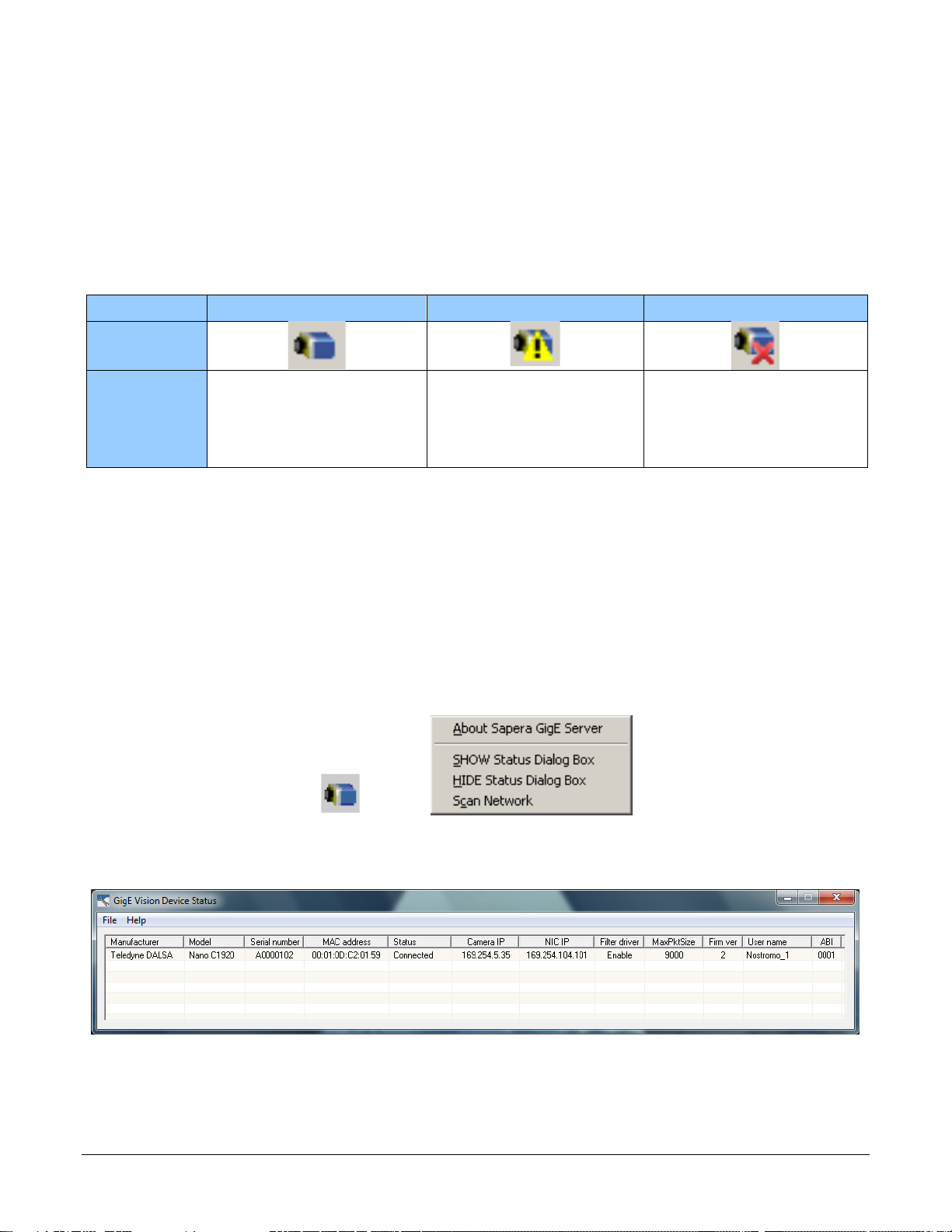
GigE Server Verification
After a successful Genie Nano Framework package installation, the GigE Server icon is visible in the
desktop taskbar tray area (note that in Windows 7 the icon remains hidden until a came ra is
connected). After connecting a camera (see following section), allow a few seconds for the GigE
Server status to update. The Nano camera must be on the same subnet as the NIC to be
recognized by the GigE Server.
Device Available Device IP Error Device Not Available
GigE Server
Tray Icon:
The normal GigE server tray
icon when the Genie device is
found. It will take a few
seconds for the GigE Server to
refresh its state after the Genie
has obtained an IP address.
The GigE server tray icon
shows a warning when a device
is connected but there is some
type of IP error.
A red X will remain over the
GigE server tray icon when the
Genie device is not found. This
indicates a major network issue.
Or in the simplest case, the
Genie is not connected.
If you place your mouse cursor on this icon, the GigE Server wil l display the number of GigE Vision
devices found by your PC. Right click the icon and se lect status to view information about those
devices. See Troubleshooting for more information.
GigE Server Status
Once the Genie Nano is assigned an IP address (its Status LED is steady blue) the GigE server tray
icon will not have a red X through it, indicating that the Nano device was found. It might take a few
seconds for the GigE Server to refresh its state after the Nano has obtained an IP address.
Right-click the GigE Server tray icon to open the following menu.
Click on Show Status to open a window listing all devices connected to the host system. Each GigE
device is listed by name along with important information such as the assigned IP address and
device MAC address. The screen shot below shows a connected Nano with no networking problems.
In the event that the device is physically connected, but the Sapera GigE Server icon is indicating
that the connected device is not recognized, click Scan Network to restart the discovery process.
Note that the GigE server periodically scans the network automatically to refresh its state. See
Troubleshooting for network problems.
82 • Using Nano with Sapera API Nano Series GigE Vision Camera

•
Optimizing the Network Adapter used with Nano
Most Gigabit network interface controllers (NIC) allow user modifications to parameters such as
Adapter Buffers and Jumbo Frames. These should be optimized f or use with the Nano during the
installation. Refer to the NetworkOptimizationGuide.pdf for optimization information (available
with the Sapera LT installation [C:\Program Files\Teledyne DALSA\N et work Interfac e] ) .
Quick Test with CamExpert (Windows)
When the Genie Nano camera is connected to a Gigabit network adapter on a host computer,
testing the installation with CamExpert is a straightforward procedure.
• Start Sapera CamExpert by double clicking the desktop icon created during the software
installation.
• CamExpert will search for installed Sapera devices. In the Device list area on the left side, the
connected Nano camera is shown or will be listed in a few seconds after CamExpert completes
the automatic device search (device discovery).
• Select the Nano camera device by clicking on the camera user defined name. By default the
Nano camera is identified by its serial number. The Nano status LED will turn green, indicating
the CamExpert application is now connected.
• Click on the Grab button for live acquisition (the Nano default is Free Running mode). Focus
and adjust the lens iris. See Operational Reference for information on CamExpert parameters
with the Nano camera.
• If the Nano has no lens, just select one of the internal test patterns available (Image Format
Controls – Test Image Selector). All but one are static images to use with the Snap or Grab
function of CamExpert. The single “moving” test image is a shifting d ia g onal ramp pattern,
which is useful for testing network/computer bandwidt h issue s (s e e fo llowing im age).
• Refer to the Teledyne DALSA Network Imaging package manual if error messages are shown in
the Output Messages pane while grabbing.
Nano Series GigE Vision Camera Using Nano with Sapera API
83

About the Device User ID
The Nano can be programmed with a user defined name to aid identifying multiple cameras
connected to the network. For instance, on an inspection system with 4 cameras, the first camera
might be labeled “top view”, the second “left view”, the third “ right view” and the last one “bottom
view”. The factory default user name is set to match the camera serial number for quick initial
identification. Note that the factory programmed Genie Nano serial number and MAC address are
not user changeable.
When using CamExper t , m ultiple Genie Nano cameras on the network are seen as different
“Nano-xxxxx” devices as an example. Non Teledyne DAL SA cameras are labeled as “GigEVision
Device”. Click on a device user name to select it for control by CamExpert.
An imaging application uses any one of these attributes to identify a camera: its IP address, MAC
address, serial number or User Name. Some important considerations are listed below.
• Do not use the camera’s IP address as identification (unless it is a persistent IP) since it can
change with each power cycle.
• A MAC address is unique to a single camera, therefore the control application is limited to the
vision system with that unique camera if it uses the camera’s MAC address.
• The User Name can be freely programmed to clearly represent the camera usage. This scheme
is recommended for an application to identify cameras. In this case, the vision system can be
duplicated any number of times with cameras identified by their function, not their serial
numbers or MAC address.
84 • Using Nano with Sapera API Nano Series GigE Vision Camera

•
Operational Reference
Using CamExpert with Genie Nano Cameras
The Sapera CamExpert tool is the interfacing tool for GigE Vision cameras, and is supported by the
Sapera library and hardware. CamExpert allows a user to test camera functions. Additionally
CamExpert saves the Nano user settings configuration to the camera or saves multiple
configurations as individual camera parameter files on the host system (*.ccf).
An important component of CamExpert is its live acquisition display window which allows
immediate verification of timing or control parameters without the need to run a separate
acquisition program.
CamExpert Panes
The various areas of the CamExpert tool are described in the summary figure below. GigE Vision
device Categories and Parameter features are displayed as per the device’s XML description file.
The number of parameters shown is dependent on the View mode selected
(i.e. Beginn er, Expert, Guru – see description below).
Nano Series GigE Vision Camera Operational Reference
85

• Device pane: View and select from any installed GigE Vision or Sapera acquisition device. After
a device is selected CamExpert will only present parameters applicable to that device.
• Parameters pane: Allows viewing or changing all acquisition parameters supported by the
acquisition device. CamExpert displays parameters only if those parameters are supported by
the installed device. This avoids conf usion by eliminating parameter choices when they do not
apply to the hardware in use.
• Display pane: Provides a live or single frame acquisition display. Frame buffer parameters are
shown in an information b ar above the image window.
• Control Buttons: The Display pane includes CamExpert control buttons. These are:
Acquisition control button:
Click once to start live grab, click again to stop.
Single frame grab:
Click to acquire one frame from device.
Software trigger button:
With the I/O control parameters set to Trigger Enable d / Softwa r e Tr igg e r
type, click to send a single software trigger comm and .
CamExpert display contro l s:
(these do not modify the frame buffer data)
Stretch (or shrink) image to fit, set image display to orig inal s iz e , or zoom
the image to any size and ratio. Note that under certain combinations of
image resolution, acquisition fr a me ra te , and host computer speed, the
CamExpert screen display may not update comp le te ly due to the host CPU
running at near 100%. This does not affect the acquisitio n.
Histogram / Profile tool:
Select to view a histogram or line/column prof i le dur ing live ac q uis ition.
• Output pane: Displays messages from CamExpert or the GigE Vision driver.
CamExpert View Parameters Option
All camera features have a Visibility attribute which defines its requirement or complexity. The
states vary from Beginner (features required for basic operation of the device) to Guru (optional
features required only for complex operations).
CamExpert presents camera features based on their visibility attribute and provides quick Visibility
level selection via controls below each Category Parameter list [ << Less More>> ]. The user can
also choose the Visibility level from the View ∙ Parameters Options menu.
86 • Operational Reference Nano Series GigE Vision Camera
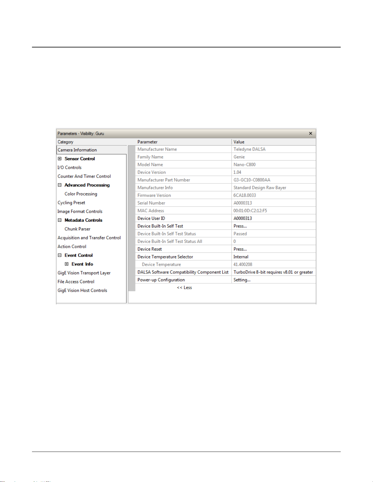
•
Camera Information Category
Camera information can be retrieved via a controlling application. Parameters such as camera
model, firmware version, etc. are read to uniquely identify the connected Nano device. These
features are typically read-only. GigE Vision applications retrieve this information to identify the
camera along with its characteristics.
Features listed in the description table but tagged as Invisible are usually for Teledyne DALSA or
third party software usage—not typically needed by end user applications.
Camera Information Feature Descriptions
The following table describes these parameters along with their view attribute and in which device
version the feature was introduced. Additionally the Device Version column will indicate which
parameter is a member of the DALSA Features Naming Convention (indicated by DFNC), versus
the GenICam Standard Features Naming Convention (SFNC tag is not shown).
New features for a major device version release will be indicated by green text f or ea s y
identification.
Nano Series GigE Vision Camera Operational Reference
87

Display Name Feature & Values Description Device
Version
& View
Manufacturer Name DeviceVendorName Displays the device vendor name. 1.00
Family Name DeviceFamilyName Displays the device family name. 1.00
Model Name DeviceModelName Displays the device model name. 1.00
Device Version DeviceVersion Displays the device version. This tag will also
Manufacturer Part
Number
Manufacturer Info DeviceManufacturerInfo This feature provides extended manufacturer
Firmware Version DeviceFirmwareVersion Displays the currently loaded firmware version
Seria l N umber DeviceSerialNumber Displays the device’s factory set serial
MAC Address deviceMacAddress Displays the unique MAC (Media Access
Device User ID DeviceUserID Feature to store a user-programmable
Device Built-In Self Test deviceBIST Command to perform an internal test which
Device Built-In Self Test
Status
Passed Passed No failure detected
Last firmware update
deviceManufacturerPartNumber Displays the device manufacturer part
deviceBISTStatus Return the status of the device Built-In Self-
FirmwareUpdateFailure Last firmware update operation failed.
failed
highlight if the firmware is a beta or custom
design. (RO)
number.
information about the device. Genie Nano
cameras show which firmware design is
currently loaded.
number. Firmware files have a unique number
and have the .cbf file extension.
number.
Control) address of the Device.
identifier of up to 15 characters. The default
factory setting is the camera serial number.
(RW)
will determine the device status. (W)
Test. Possible return v al u es are devicespecific.
Beginner
Beginner
Beginner
1.00
Beginner
1.00
DFNC
Beginner
1.00
Beginner
1.00
Beginner
1.00
Expert
1.00
DFNC
Beginner
1.00
Beginner
1.00
Beginner
1.00
Beginner
Unexpected Error Unexpected_Error Switched to recovery mode due to unexp ected
Sensor Initialization
Device Built-In Self Test
Status All
Device Reset DeviceReset Resets the device to its power up state. (W) 1.00
Device Temperature
Selector
Failure
Firmware Error FirmwareError Firmware encountered an error during
deviceBISTStatusAll Return the status of the device Built-In Self-
DeviceTemperatureSelector Select the source where the temperature is
Internal Internal Value from FPGA and or PHY temperature.
MaxInternal MaxInternal Records the highest device temperature sinc e
SensorFailure There was an error initializing the sensor. The
software error.
camera may not be able to capture images.
(1.05)
streaming.
(1.06)
Test as a bitfield. The meaning for each bit is
device-specific. A value of 0 indicates no
error.
Bit-0=1:Firmware Update Failure
Bit-2=1:Unexpected Error
read.
power up. Value is reset on power off .
1.00
DFNC
Beginner
Beginner
1.00
Beginner
88 • Operational Reference Nano Series GigE Vision Camera

•
Power-up Config uration
UserSetDefault
Specify the camera configuration set to load
stored in camera non-volatile memory .
Device Temperature DeviceTemperature The temperature of the selected source in
DALSA Software
Compatibility
Component List
TurboDrive 8-bit
requires v8.01
or greater
TurboDrive 10-bit
requires v8.10 or
greater
TurboDrive 12-bit
requires v8.10 or
greater
Multicast requires a
newer version
Power-up Config uration
Selector
Factory Setting Default Load factory default feature settings.
UserSet1 UserSet1 Select the user defined configuration UserSet
UserSet2 UserSet2 Select the user defined configuration Us erSet
User Set Selector UserSetSelector Selects the camera configuration set to load
Factory Setting Default Select the default camera feature settings
UserSet 1 UserSet1 Select the User Defined Configu ra tio n sp a c e
UserSet 2 UserSet2 Select the User Defined Configu ra tio n sp a c e
Load Configuration UserSetLoad Loads the camera configuration set specified
Save Configuration UserSetSave Saves the current camera configuration to the
Selector
DALSASoftwareCompatibilityComponentList List the optional Teledyne DALSA software
Compatibility1 Teledyne DALSA Turbo Drive 8-bit
Compatibility2 Teledyne DALSA Turbo Drive 10-bit
Compatibility3 Teledyne DALSA Turbo Drive 12-bit
Compatibility4 Multicast feature support requires a newer
UserSetDefaultSelector Selects the camera configuration set to load
degrees Celsius. Maximum temperature
should not exceed +70°C for reliable
operation.
functions that are supported.
(Monochrome or Bayer) requires Sapera-LT
8.01 or greater.
(Monochrome or Bayer) requires Sapera-LT
8.10 or greater.
(Monochrome or Bayer) requires Sapera-LT
8.10 or greater.
version of Sapera LT than currently installed.
and make active on camera power-up or
reset. The camera configuration sets are
stored in camera non-volatile memory . ( RW)
1 as the Power-up Configuration.
2 as the Power-up Configuration.
feature settings from or save current feature
settings to. The Factory set contains default
camera feature settings. (RW)
saved by the factory.
UserSet1 to save to or load from features
settings previously saved by the user.
UserSet1 to save to or load from features
settings previously saved by the user.
by the User Set Selector feature, to the
camera and makes it active. Can not be
updated during a Sapera transfer. (W)
user set specified by the User Set Sel ector
feature. The user sets are located on the
camera in non-volatile memory. (W)
and make active on camera power-up or
reset. The camera configuration sets are
1.00
Beginner
1.00
Beginner
1.00
Beginner
1.00
Beginner
1.00
Beginner
1.00
Beginner
1.00
Beginner
Seria l N umber DeviceID Displays the device’s factory set camera s eri al
Factory Setting Default Select the Factory Setting values as the
UserSet1 UserSet1 Select the user defined configuration UserSet
UserSet2 UserSet2 Select the user defined configuration UserSet
Nano Series GigE Vision Camera Operational Reference
number.
Power-up Configuration.
1 as the Power-up Configuration.
2 as the Power-up Configuration.
1.00
Invisible
1.00
Invisible
89

Calibration Date deviceCalibrationDateRaw Date when the camera was calibrated.
Device Acquisition Type deviceAcquisitionType Displays the Device Acquisition Type of the
product.
Sensor Sensor The device gets its data directly from a
sensor.
Device TL Type DeviceTLType Transport Layer type of the device. 1.00
GigE Vision GigEVision GigE Vision Transport Layer
Device TL Version Major DeviceTLVersionMajor Major version of the device’s Transport Layer. 1.00
Device TL Version Minor DeviceTLVersionMinor Minor version of the device’s Transport Layer.
userSetError Error Flags for UserSetLoad & UserSetSave 1.00
NoError No Error
LoadGenericError Unknown error
LoadBusyError The camera is busy and cannot perform the
action
LoadMemoryError Not enough memory to load set
LoadFileError Internal file I/O error
LoadInvalidSetError At least one register could not be restored
properly
LoadResourceManagerError An internal error happened related to the
resource manager
SaveGenericError Unknown error
SaveBusyError The camera is busy and cannot perform the
action
SaveMemoryError Camera ran out of memory while saving set
SaveFileError Internal file I/O error
SaveInvalidSetError An invalid user set was requested
SaveResourceManagerError An internal error happened related to the
resource manager
DFNC Major Rev deviceDFNCVersionMajor Major revision of Dalsa Feature Naming
Convention which was used to create the
device’s XML.
DFNC Minor Rev deviceDFNCVersionMinor Minor revision of Dalsa Feature Naming
Convention which was used to create the
device’s XML.
SFNC Major Rev DeviceSFNCVersionMajor Major Version of the Genicam Standard
Features Naming Convention which was used
to create the device’s XML.
SFNC Minor Rev DeviceSFNCVersionMinor Minor Version of the Genicam Standard
Features Naming Convention which was used
to create the device’s XML.
SFNC SubMinor Rev DeviceSFNCVersionSubMinor SubMinor Version of the Genicam Standard
Features Naming Convention which was used
to create the device’s XML.
1.00
DFNC
Invisible
DFNC
Invisible
Invisible
Invisible
1.00
DFNC
Invisible
1.00
DFNC
Invisible
1.00
DFNC
Invisible
1.00
DFNC
Invisible
1.00
Invisible
90 • Operational Reference Nano Series GigE Vision Camera

•
Power-up Configuration Dialog
CamExpert provides a dialog box which combines the features to select the camera power-up state
and for the user to save or load a Nano camera state.
Camera Power-up Configuration
The first drop list selects the camera configuration state to load on power-up (see feature
UserSetDefaultSelector). The user chooses from one factory data set or one of two possible user
saved states.
Load / Save Configuration
The second drop list allows the user to change the camera configuratio n any time after a power-up
(see feature UserSetSelector). To reset the camera to the factory configuration, select Factory
Setting and click Load. To save a current camera configuration, select User Set 1 or 2 and click
Save. Select a saved user set and click Load to restore a saved configuration.
Nano Series GigE Vision Camera Operational Reference
91

Sensor Control Category
The Genie Nano sensor controls, as shown by CamExpert, groups sensor specific parameters. This
group includes controls for frame rate, exposure time, gain, etc. Parameters in gray are read only,
either always or due to other feature settings. Parameters in black are user set in CamExpert or
programmable via an imaging application.
Features listed in the description table that are tagged as Invisible are usually for Teledyne DALSA
or third party software usage—not typically needed by end user applications. Also important,
features shown by CamExpert may change with different Genie Nano models imp lementing
different sens ors, image resolutions, and color versions.
92 • Operational Reference Nano Series GigE Vision Camera

•
Sensor Control Feature Descriptions
The following table describes these features along with their view attribute and device version. For each feature the device version may differ
for each camera sensor available.
When a Device Version number is indicated, this represents the camera software functional group, not a firmware revision number. As Genie
Nano capabilities evolve the device version will increase, therefore identifying the supported function package. New features for a major
device version release will be indicated by green text for easy identification.
The first column indicates whether a feature applies to monochrome or color camera models via a symbol. No symbol indicates a common
feature. Additionally the description column will indicate which feature is a member of the DALSA Features Naming Convention (indicated by
DFNC), versus the GenICam Standard Features Naming Convention (SFNC tag is not shown).
B/W
Color
Display Name Feature & Values Description
Device Scan Type DeviceScanType Defines the scan type of the device’s sensor.
Areascan Areascan Device uses an Areascan sensor.
Sensor Color Type sensorColorType Defines the camera sensor color type.
Monochrome Sensor Monochrome Sensor color type is monochrome.
Bayer Sensor CFA_Bayer Sensor color type is Bayer Color Filter Array (CFA).
Input Pixel Size pixelSizeInput Size of the image input pixe ls, in bit s per pix el.
12 Bits/Pixel Bpp12 Sensor output data path is 12 bits per pixel.
Sensor Width SensorWidth Defines the sensor width in active pixels.
Sensor Height SensorHeight Defines the sensor height in active lines.
Acquisition Frame Rate
Control Mode
Acquisition Frame Rate AcquisitionFrameRate Specifies the camera internal frame r at e, in Hz.
8 Bits/Pixel Bpp8 Sensor output data path is 8 bits per pixel.
10 Bits/Pixel Bpp10 Sensor output data path is 10 bits per pixel.
acquisitionFrameRateControlMode Set the frame control method used in free running mode. Note that this feature applies only to
Maximum Speed MaximumSpeed The camera operates at its maximum frame rate using the current exposure (time and delay)
Genie Nano is an Areascan camera.
< RO, Beginner >
< RO, DFNC, Beginner >
< RO, DFNC, Guru >
< RO, Expert >
< RO, Expert >
sensor acquisitions, not internal test images. < 1.01, DFNC, Guru >
configuration.
Any user entered value is automatically adjusted to a valid camera value. Note that a change in
frame rate takes effect only when the acquisition is stopped and restarted.
< Beginner >
Notes
Programmable Programmable The camera frame rate is controlled by the AcquisitionFrameRate feature.
Nano Series GigE Vision Camera Operational Reference
93

Exposure Mode ExposureMode Sets the operation mode for the camera’s exposure (or electronic shutter).
Exposure Alignment
Exposure Delay exposureDelay Specifies the delay in microseconds (µs) to apply after the FrameStart event before starting the
Exposure Time ExposureTime Sets the exposure time (in microseconds) when th e Exp os ur e M od e feat u re i s set to Timed.
Actual Exposure Time exposureTimeActual Actual Exposure Time performed by sensor due to it s d esign, based on the requested Exposure
Sensor Shutter Mode SensorShutterMode States or selects the supported shutter mode of the device.
Rolling Rolling The shutter opens and closes sequentially for groups (typically lines) of pixels.
Timed Timed The exposure duration time is set using the Exposure Time feature and the exposure starts with a
Trigger Width TriggerWidth Uses the width of the trigger signal pulse to control the exposure duration. Use the Trigger
exposureAlignment Exposure Alignment sp ecifies how the exposure is executed in rel a tionship to the sensor capabili ti es
Synchronous Synchronous Exposure is synchronous to the internal timing of the sensor. The readout is concurrent to the
Reset Reset Sensor timing is reset to initia te exposure when a valid trigger is received. Readout is sequential to
Global Global The shutter exposes all pixels at the same time.
Global Reset GlobalReset The shutter opens at the same time for all pixels but ends in a line sequential manner.
< Beginner >
FrameStart event.
Activation feature to set the polarity of the trigger.
The Trigger Width setting is applicable with Trigger Selector = Single Frame Trigger(Start).
and current frame trigger.
< DFNC Beginner >
exposure for the fastest pos sible frame rate. When a valid trigger i s received and the ExposureTime
is shorter than the readout period, the ExposureStart event is latched in the previous frame’s
readout. That is; the ExposureStartEvent is delayed and is initiated when the actual exposure starts
such that the exposure ends and readout begins as soon as the previous readout has completed.
exposure, reducing the maximum achievable frame rates. Tha t i s, a trigg er r eceived during
exposure or readout is ignored since data would be lost by performing a reset.
ExposureStart event.
< DFNC Beginner >
< Beginner >
Time.
< Beginner >
< Beginner >
Ver. 1.06
Gain Selector GainSelector Selects which gain is controlled when adjusting gain features.
Sensor SensorAll Apply a gain adjustment within the sensor to the entire image. The first half of the gain range is
Gain Gain Sets the selected gain as an amplification factor applied to the image. User adjusts the Gain feature
Gain (Raw) GainRaw Raw Gain value that is set in camera (Model Specific for range and step values).
Sensor Analog SensorAnalog Apply an analog gain adjustment within the sensor to the entire image.
Sensor Digital SensorDigital Apply a digital gain adjustment within the sensor to the entire image.
Digital DigitalAll Apply a digital gain adjustment to the entire image. This independent gain factor is applied to the
< Beginner >
applied in the analog domain and the second half is digital.
image after the sensor.
or the GainRaw feature.
< Beginner >
< Guru>
ver. 1-02
ver. 1.02
94 • Operational Reference Nano Series GigE Vision Camera

•
Black Level Selector BlackLevelSelector Selects which Black Level to adjust using the Black Level features.
Analog AnalogAll Sensor Dark Offset
Black Level BlackLevel Controls the black level as an absolute physical value. This represents a DC offset applied to the
Fast Readout Mode
Sensor FPN Correction
Mode
Active Active When this mode is active, the row blanking and row readout occur in parallel in the sensor. This
Active Active Enables the sensor FPN Correction Mode.
fastReadoutMode Selects the sensor’s readout mode.
Off Off When this mode is off, the row blanking and row readout occur sequentially in the sensor.
sensorFpnCorrectionMode Activation mode for the sensor Fixed Pattern Noise correction function.
Off Off Disables the sensor FPN Correction Mode
< Beginner >
video signal, in DN (digital number) units. The Black Level Selector feature specifies the channel to
adjust.
< Beginner >
< Guru, 1.01 >
helps achieve a lower total frame readout time resulting in a faster maximum frame rate. There are
minor DN column artifacts, typically of no significance.
< Guru, 1.01 >
Note: Applicable to the models listed below
M640, M640 NIR, C640
M800, M800 NIR, C800
M1280, M1280 NIR, C1280
ver. 1.02
ver. 1.02
Nano Series GigE Vision Camera Operational Reference
95

Offset/Gain Control Details (Sony sensors)
Sensor Gain Control
Post Digital Gain Control
Sony Sensor Gain Stages
Analog Digital
Black Level
Control
Digital
The Gain and Black level functions are applied at the sensor and/or on the digital image values
output by the sensor, as described below.
• Gain Selector = Sensor: The gain function is a linear multiplier cont rol in 0.01 steps within
the sensor hardware (range is “1-251”, which is a +48dB maximum gain).
• Gain: Sensor gain is applied first by an analog amplifier (multiplier range of “1-15.85”,
i.e. +24dB) and then contin ues automatically via a digital amplifier as shown in the graphic
below.
• Important: Digita l noise increases li nearly and quickly with higher gain values . Users should
evaluate image quality with added gain.
• Gain (Raw): P ro v ides an alternative method to control sensor gain, where values entered are
in 0.1dB increments. Therefore the range is 0 to 480 which controls a 0 to 48dB gain range.
• Gain Selector = Digital: The gain function controls the post sensor digital amplifier (available
only on some models of Na no cameras). This gain factor is independent of any sensor gain set.
This setting is a linear multiplying number of 1 to 4, in 0.1 steps).
• Black Level: This offset variable exists within the sensor. The Sony sensors allow an offset
range between 0 and 511 DN. The factory settings default value for each sensor used by
various Nano models, is recommended as per the sensor manufacturer design specifications.
Note: With the factory default offset, testing a camera’s black output in 8-bit mode may show
a 2 DN value difference across the image. Changing the Black Level value up or down will push
sensor noise (present at the sensors native bits per pixel) to fall within one 8-bit value, thus the
noise becomes hidden.
Sony Sensors Gain Stage Diagram
96 • Operational Reference Nano Series GigE Vision Camera

•
Analog Gain Control
Post Digital Gain Control
On-Semi Sensor Gain Stages
Analog
Black Level
Control
Digital
Digital
Digital Gain Control
Offset/Gain Control Details (On-Semi Python sensors)
The Gain and Black level functions are applied at the sensor and/or on the digital image values
output by the sensor, as described below.
• Gain Selector = Sensor Analog: The gain f unction is a linear multiplier control in 0.01 steps
within the sensor hardware (Gain range is “1-8”, which is a +18dB gain).
• Gain Selector = Sensor Digital: The gain function is a linear multiplier control in 0.01 steps
within the sensor hardware (Gain range is “1-31.99”, which is +30dB gain).
• Important: Digital noise increases linearly and quickly with higher gain values. Users should
evaluate image quality with added gain.
• Gain (Raw): Shows the raw sensor control for each gain stage or an alternative method to
control sensor gain.
• Black Level: This offset variable exists within the sensor. The On-Semi sensors allow an offset
range between 0 and 255 DN. The factory settings default value for each sensor used by
various Nano models, is recommended as per the sensor manufacturer design specifications.
Note: With the factory default offset, testing a camera’s black output in 8-bit mode may show
a 2 DN value differenc e ac ross the image. Changing the Black Level value up or down will push
sensor noise (present at the sensors native bits per pixel) to fall within one 8-bit value, thus the
noise becomes hidden.
On-Semi Python Sensors Gain Stage Diagram
Nano Series GigE Vision Camera Operational Reference
97

Bayer Mosaic Pattern
Genie Nano Color cameras output raw Bayer image data using the mosaic pattern shown below.
Teledyne DALSA Sapera CamExpert tool interprets the raw Bayer output when the user enables the
Pre-Processing Software Bay er Decoder. CamExpert also provides an automatic white balance tool
to aid RGB gain adjustments.
Bayer Mosaic Pattern and the CamExpert processing f unction to decode th e G e nie Nano Color
OnSemi Python P1 Sensor Artifacts with Fast Readout Mode
Nano OnSemi (Python P1) sensor camera models with Fast Readout mode active have the row
blanking and row readout occur in parallel in the sensor. This reduces the total frame readout time
resulting in a faster maximum frame rate. As a consequence there are minor column artifacts (of
very low DN) which are typically of no significance and irrelevant for many imaging syst ems. Note
that these column artifacts will become more prominent as sensor gain is increased.
The image below shows a “dark” capture with Fast Readout Mode enabled and analog gain set to
maximum (8x). The artifacts will become visible as fixed pattern DN column variations near the left
edge of the video frame. There are darker columns followed by lighter columns as marked by the
overlay graphics. These DN variations are not random columns, but consistent between individual
OnSemi sensors operating in Fast Readout mode with high gain.
98 • Operational Reference Nano Series GigE Vision Camera
 Loading...