

Teledyne 9060 User Manual

9060-Zirconia Analyser
TELEDYNE ANALYTICAL INSTRUMENTS
OPERATING & INSTRUCTION
MANUAL
Model 9060
Zirconia Oxygen Analyser
9060/2006

9060-Zirconia Analyser
CONTENTS
1. SPECIFICATIONS
2. DESCRIPTION
3. INSTALLATION & COMMISSIONING
4. OPERATORS FUNCTIONS - ALARMS
5. SETTING UP THE TRANSMITTER
6. MAINTENANCE
APPENDICES
1. CONSTITUENT VALUES FOR VARIOUS FUELS
2. PROBE OR SENSOR EMF TABLES
3. LOG OXYGEN SCALE
4. SAMPLE LOG PRINT OUT
5. CIRCUIT SCHEMATIC
6. MODBUS™ REGISTER MAP
DECLARATION OF CONFORMITY (LAST PAGE)
Note: This manual includes software modifications up to Version 2.25, October 2005
© Copyright TELEDYNE ANALYTICAL INSTRUMENTS - 1996 - 2006
Neither the whole nor any part of the information contained in, or the product described in, this manual may
be adapted or reproduced in any material form except with the prior written approval of Teledyne Analytical
Instruments (Teledyne Analytical Instruments).
The product described in this manual and products for use with it, are subject to continuous developments
and improvement. All information of a technical nature and particulars of the product and its use (including
the information in this manual) are given by Teledyne Analytical Instruments in good faith. However, it is
acknowledged that there may be errors or omissions in this manual. A list of details of any amendments or
revisions to this manual can be obtained upon request from Teledyne Analytical Instruments Technical
Enquires. Teledyne Analytical Instruments welcome comments and suggestions relating to the product and
this manual.
All correspondence should be addressed to:
Technical Enquires
Teledyne Analytical Instruments
16830 Chestnut Street
City of Industry Phone: 626 934 1500
CA 91748
USA Fax: 626 961 2538
All maintenance and service on the product should be carried out by Teledyne Analytical Instruments’
authorised dealers. Teledyne Analytical Instruments can accept no liability whatsoever for any loss or
damage caused by service or maintenance by unauthorised personnel. This manual is intended only to
assist the reader in the use of the product, and therefore Teledyne Analytical Instruments shall not be liable
for any loss or damage whatsoever arising from the use of any information or particulars in, or any error or
omission in, this manual, or any incorrect use of the product.

9060-Zirconia Analyser
USING THIS MANUAL
The Teledyne 9060 Oxygen Transmitter has a variety of user-selectable functions.
They are simple to use because each selection is menu driven. For options you are not
sure about; read the manual on that particular item.
Please read the safety information below and the ‘Installation’ section before connecting
power to the transmitter.
CAUTION 1
The probe or sensor heater is supplied with mains voltage. This supply has electrical shock danger to
maintenance personnel. Always isolate the transmitter before working with the probe or sensor, gas
solenoids, or the transmitter.
The EARTH wire (green) from a heated probe or sensor must ALWAYS be connected to earth.
CAUTION 2
Combustion or atmosphere control systems can be dangerous. Burners must be mechanically set up so that
in the worst case of equipment failure, the system cannot generate explosive atmospheres. This danger is
normally avoided with flue gas trim systems by adjustment so that in the case of failure the appliance will not
generate CO in excess of 400 ppm in the flue. The CO level in the flue should be measured with a separate
CO instrument, normally an infrared or cell type.
CAUTION 3
The oxygen sensor which is heated to over 700°C (1300°F) and is a source of ignition. Since raw fuel leaks
can occur during burner shutdown, the transmitter has an interlocking relay that removes power from the
probe or sensor heater when the main fuel shut-off valve power is off. If this configuration does not suit or if
it is possible for raw fuel to come into contact with a hot oxygen probe or sensor then the Model 9060
Analyser with a heated probe or sensor will not be safe in your application.
An unheated probe can be utilised in such applications, however the oxygen readings are valid only above
650°C (1200°F).
CAUTION 4
The reducing oxygen signal from the transmitter and the associated alarm relay can be used as an explosive
warning or trip. This measurement assumes complete combustion. If incomplete combustion is possible
then this signal will read less reducing and should not be used as an alarm or trip. A true excess
combustibles transmitter, normally incorporating a catalyst or thermal conductivity bridge, would be more
appropriate where incomplete combustion is possible.
Also read the probe or sensor electrical shock caution in Section 2.5 and the probe or sensor heater
interlock caution in Section 3.6.
CAUTION 5
If an external pressure transducer is used to feed the process pressure to the transmitter for pressure
compensation, it is essential that the pressure transducer is accurate and reliable. An incorrect reading of
pressure will result in an incorrect reading of oxygen. It is therefore possible that an explosive level of fuel
could be calculated in the transmitter as a safe mixture.
CAUTION 6
FIL-3 filter. If the optional FIL-3 has been fitted to the 1231 probe in this installation, please read the
Important Notice in section 1.2.
3
3

9060-Zirconia Analyser
SPECIFICATIONS
1
1.1 MODEL 9060 OXYGEN ANALYSER FOR TWO OXYGEN SENSORS
1.2 SERIES 1230 OXYGEN PROBES AND SENSORS
1.3 PURGE & CALIBRATION CHECK ACCESSORIES
1.4 FILTER PURGE SWITCH

9060-Zirconia Analyser
1.1 MODEL 9060 OXYGEN ANALYSER FOR TWO OXYGEN PROBES
DESCRIPTION
The Teledyne Model 9060 oxygen analyser/ transmitter provides in-situ measurement for
two oxygen probes in furnaces, kilns and boilers and flue gases with temperatures from
ambient up to 1400°C (2550°F). The transmitter provides local indication of oxygen plus
thirteen other selectable variables.
One or two probes or sensors in one process can be controlled from one transmitter
providing an average and/or individual sensor signals. Two linearised and isolated 4 to 20
mA output signals are provided. Alarms are displayed at the transmitter and relay contacts
activate remote alarm devices. The transmitter, which is available for heated or unheated
zirconia oxygen probes, provides automatic on-line gas calibration check of the probe and
filter purging. The electronics self-calibrates all inputs every minute.
The 9060 has a keyboard for selecting the output range, thermocouple type, etc., as well
as maintenance and commissioning functions. The instrument is microprocessor based
and all adjustments are made using the keyboard.
• Used for air / fuel ratio combustion control to provide fuel savings
• Used for product quality control in ceramic and metal processing industries
• Simple to install
• Linear output of % oxygen for recording or control
• Built in safety features
• 26 different alarm conditions that warn the operator of combustion, probe, or
transmitter problems
• Isolated RS 232-C printer/computer interface and an RS 485 MODBUS network
interface
• Safety interlock relay for heated probes
5
5
9060-Zirconia Analyser
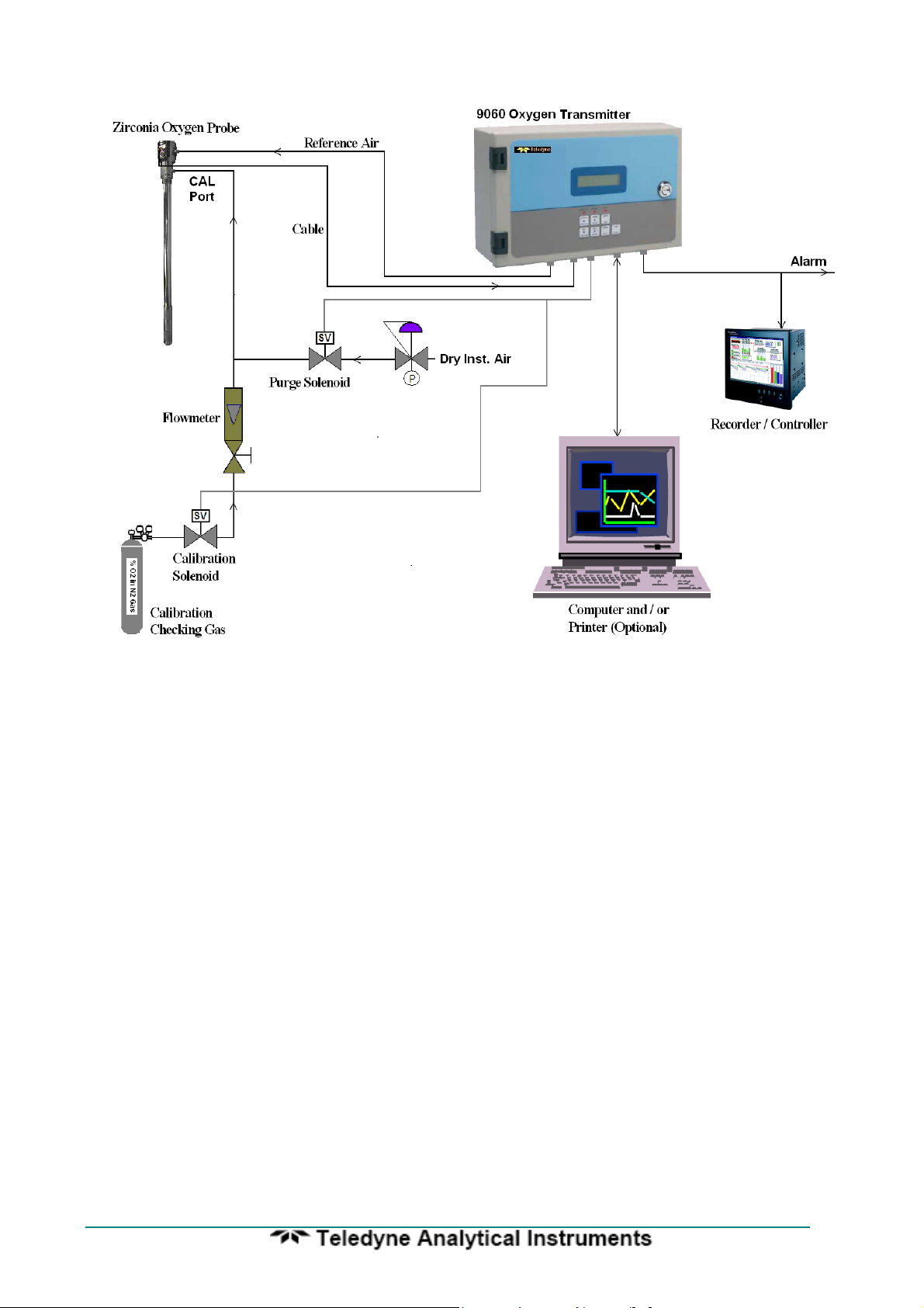
Oxygen Probe and Transmitter System

9060-Zirconia Analyser
SPECIFICATIONS
Inputs
• Zirconia oxygen probe, heated or unheated
• Furnace, kiln or flue thermocouple, field selectable as type K or R.
• Main flame established safety interlock (for heated probes only)
• Purge pressure switch
• Dual Fuel selector
• Remote alarm accept
Outputs
• Two linearised 4 to 20 mA DC outputs, max. load 1000Ω
• Common alarm relay
• Three other alarm relays with selectable functions
Computer
• RS 232-C or RS 485 for connection of a computer terminal or printer for diagnostics of
the transmitter, probe, sensor or combustion process. This connection is suitable for
network connection to computers, DCSs or PLCs using MODBUS protocol.
Range of Output 1
Field selectable from the following:
Output Selection Range
Linear, Probe 1 0 to 1% oxygen to 0 to 100 % oxygen
Linear, Probe 1 and 2 averaged 0 to 1% oxygen to 0 to 100 % oxygen
(If 2 probes are used)
Log 0.1 to 20 % oxygen, fixed
Reducing 100 % to 10-4 oxygen, fixed
Reducing 10-1 to 10
Linear, probe 1, very low range 0 to 0.001% to 0 to 2.0 % oxygen (10ppm to 20,000ppm)
Range of Output 2
Field selectable from the following:
Output Zero Range Span Range
Sensor EMF 0 to 1100 mV in 100 mV steps 1000 to 1300 mV in 100
mV steps
Carbon Dioxide 0 to 10 % 2 to 20 %
Oxygen Deficiency 0 to 20% O2 deficiency 0 to 100% O2 excess
Aux Temperature 0 to 100°C (32 to 210°F) in 1 degree steps 100 to 1400°C (210 to
2550°F) in 100 degree
steps
Log Oxygen 0.1% O2 Fixed 20% O2 Fixed
Reducing Oxygen 10+2 (100%) to 10
decade steps, non-overlapping in one decade steps. Min
span two decades.
Linear Oxygen, probe 2 0% oxygen, fixed 1 to 100%
Combustibles %, Probe 1 0% combustibles fixed 0.5 to 2.0 %
Linear, Probe 1 and 2 averaged 0% oxygen, fixed 1 to 100%
(If 2 probes are used)
-25
% oxygen, fixed
-10
% oxygen in one 10-3 to 10
-30
% oxygen
7
7

9060-Zirconia Analyser
Range of Indication, Upper Line
• Auto ranging from 10
Indication Choice, Lower Line
Any or all of the following can be selected for lower line display:
• Date - time
• Run Hours since last service
• Date of last service
• Probe 1 oxygen
• Probe 2 oxygen
• Probe 1 EMF
• Probe 2 EMF
• Probe 1 Temperature
• Auxiliary Temperature
• Probe 2 Temperature
• Probe 1 Impedance
• Probe 2 Impedance
• Ambient Temperature
• Ambient Relative Humidity
• Carbon Dioxide
• Combustibles
• Oxygen Deficiency
The oxygen deficiency output can be used in the same way as a combustibles transmitter
to signal the extent of reducing conditions of combustion processes.
Accuracy
• ±1% of actual measured oxygen value with a repeatability of ±0.5% of measured value.
Relay Contacts
• 0.5A 24 VAC, 1A 36 VDC
Environmental Rating
• Operating Temperature: -25 to 55°C (-15 to 130°F)
• Relative Humidity: 5 to 95% (non-condensing)
• Vibration: 10 to 150Hz (2g peak)
Power Requirements
• 240 or 110V, 50/60 Hz, 105 VA (heated probe)
• 240 or 110V, 50/60 Hz, 5 VA (unheated probe)
-30
to 100% 02

9060-Zirconia Analyser
Weight
• Transmitter, 3.75 kg (10 lbs.)
Dimensions
• 280mm (11”) W x 180mm (7”) H x 95mm (3.75”) D
Degree of Protection
• IP65 without reference air pump
• IP54 with reference air pump
Mounting
• Suitable for wall or surface mounting.
9
9
9060-Zirconia Analyser
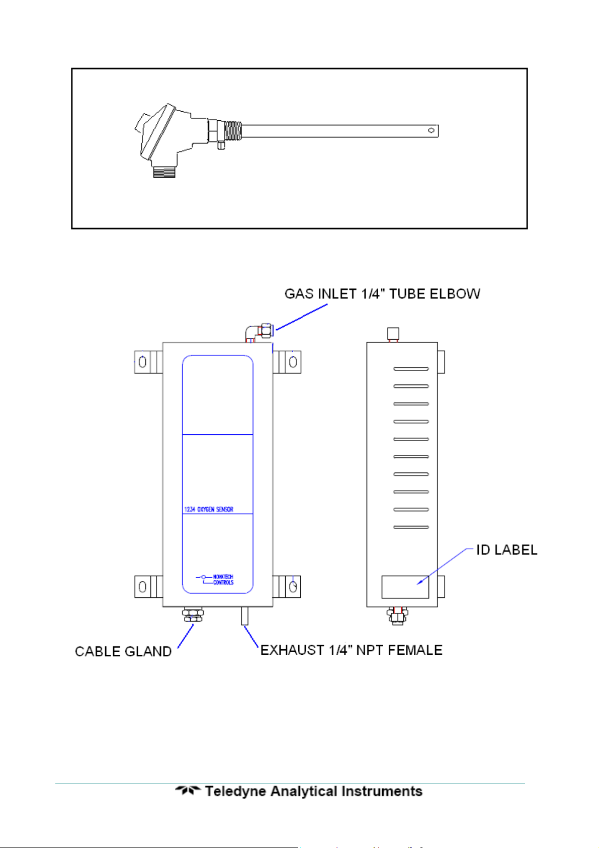
1.2 SERIES 1230 OXYGEN PROBES & SENSORS
DESCRIPTION
Teledyne series 1230 oxygen probes and sensors employ state-of-the-art zirconia sensors
and advanced materials, which provide the following benefits:
• Improved control due to fast response time to typically less than four seconds
• Cost-efficient design provides improved reliability
• Longer-life probes with greater resistance to corrosion from sulphur and zinc
contaminants in flue gas
• Low cost allows maintenance by replacement
• Reduced probe breakage due to greater resistance to thermal shock and mechanical
damage during installation and start-up
Series 1230 probe or sensors are simple to install and maintain. All models provide direct
measurement of oxygen level. On-line automatic calibration check is available if required.
Probes or sensors may be used with Teledyne oxygen transmitters and some model
transmitters from other manufacturers. See Set-up 5.5.90 for more details.
All Novatech oxygen probe or sensors are designed and manufactured to exacting
standards of performance and reliability. Series 1230 probe or sensors are the result of
extensive research and development by Novatech, industry and government agencies.
Teledyne Analytical Instruments provides application and after sales support for oxygen
probes, sensors and transmitters, worldwide.
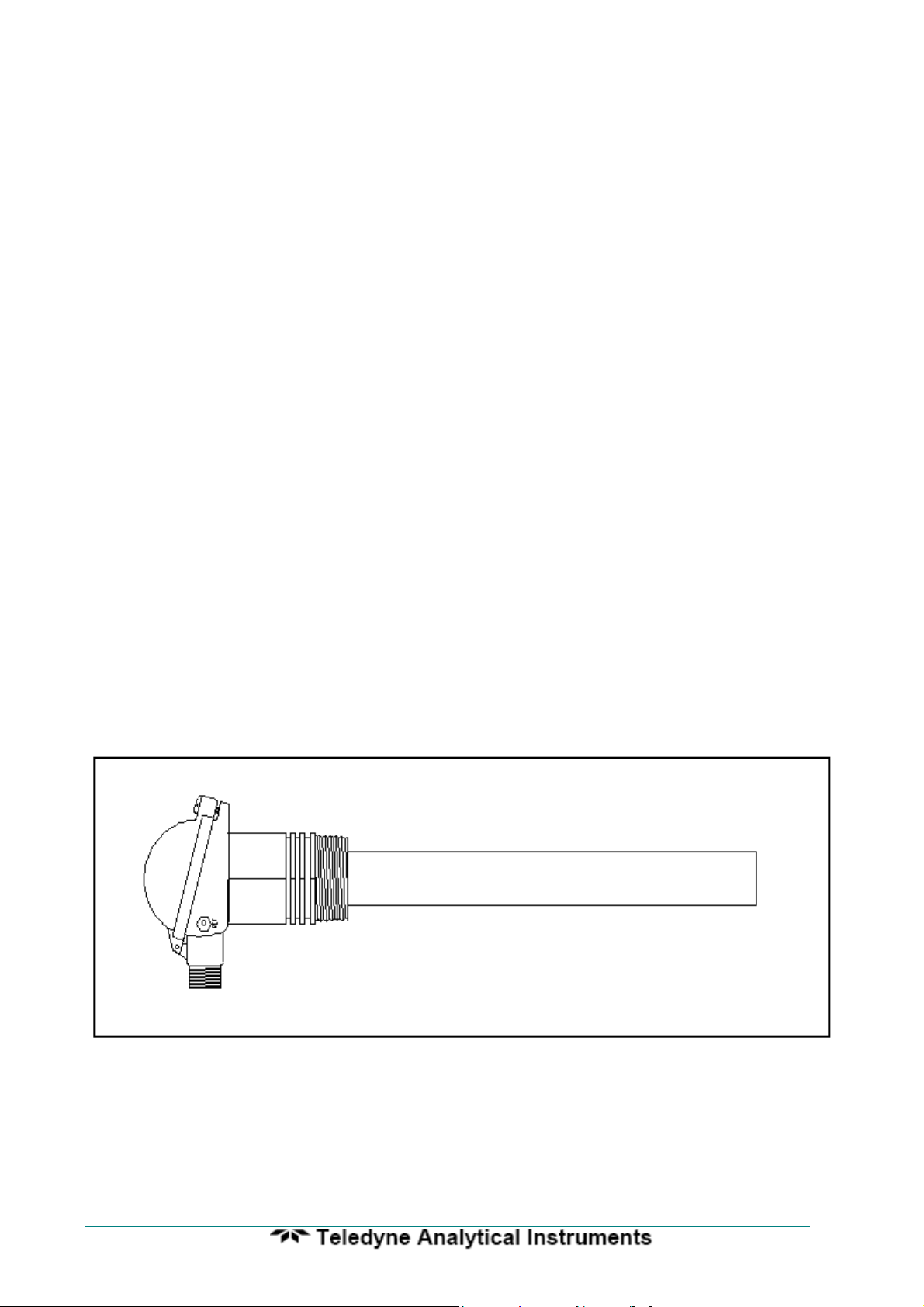
Model 1231 Heated Oxygen Probe
9060-Zirconia Analyser
Model 1232 Unheated Oxygen Probe
Model 1234 Oxygen Sensor
11
11

9060-Zirconia Analyser
STANDARD PROBE ‘U’ LENGTHS
1231 1232
250 mm (10”) 500 mm (20”)
350 mm (14”) 750 mm (30”)
500 mm (20”) 1000 mm (40”)
750 mm (30”) 1500 mm (60”)
1000 mm (40”)
1500 mm (60”)
2000 mm (80”)
1. Probe insertion length (from process end of mounting thread to probe sensing tip).
2. Mounting thread (process connection), BSP or NPT (for size of thread refer to
specifications).
3. Lagging extension length, if required.
4. If model 1232 probe, state preferred thermocouple type (refer to specifications).
Ordering Information

9060-Zirconia Analyser
Important Notice Regarding
1231 Probe Option - FIL-3
WARNING: The only identifiable standard for flame arresters for general use is British
Standard BS EN 12874:2001. British Standard BS EN 12874:2001 refers to an operating
environment up to 150 Degrees Centigrade.
The FIL-3 device optionally fitted to 1231 Heated Zirconia Probes (the “Probes" or "Probe")
operate in an environment considerably greater than 150 Degrees Centigrade.
Therefore, we know of no Australian, British, European or USA standard applicable to
flame arresters or their testing above 150 degrees Centigrade. Consequently, the FIL-3
device cannot be certified as a safety device.
The probe is only one of several potential sources of ignition. Extreme care is required
when using the probes during the start up processes of a combustion appliance.
The Teledyne Burner Interlock Relay facility, which is a standard part of the Teledyne
transmitter, is designed to be wired to the main safety shut-off fuel valves in a way that can
shutdown the probe heater when the fuel valves are closed.
The risk of ignition of flammable gas mixture at the hot end of the Probe can only be
minimised by correct use, maintenance and operation of the FIL-3 device. The user of the
FIL-3 device is responsible for verification and maintenance and correct use and operation
of the FIL-3 device.
THE USER AGREES THAT IT USES THE PROBE AND THE FIL-3 DEVICE AT ITS
SOLE RISK. TELEDYNE ANALYTICAL INSTRUMETS , TO THE FULL EXTENT
PERMITTED BY LAW, GIVES NO WARRANTIES OR ASSURANCES AND EXCLUDES
ALL LIABILITY (INCLUDING LIABILITY FOR NEGLIGENCE) IN RELATION TO THE
PROBE AND THE FIL-3 DEVICE.
The user must ensure that it correctly follows all instructions in relation to the Probe and
FIL-3 device, correctly understands the specifications of the Probe and FIL-3 device and
ensures that the Probe and FIL-3 device are regularly inspected and maintained.
FIL-3 equipped Probes should be inspected at least once a year for corrosion and more
frequently if there is any reason to suspect that corrosion may have occurred.
13
13

9060-Zirconia Analyser
OXYGEN PROBE SPECIFICATIONS
MODEL 1231 1232
Application Combustion flue Combustion flue gases
Refer to note 1 eg. natural gas, light oils
Temp. Range 0 to 900°C. Refer to note 2 700 to 1400°C
(32 to 1650°F) (1470 to 2550°F)
Length 250 to 2000 mm 500 to 1500 mm
(10” to 80”) (20” to 60”)
Process 1 ½" BSP ¾" BSP
Connection or NPT or NPT
Electrical Weatherproof plug-in connector or optional screw terminals. The
Connection plug connector can be supplied with the cable.
Cable Order a specific length with the transmitter
Heater Yes No
Thermocouple K, integral R, integral
Response Time Typically < 4 secs. Typically < 1 sec
Head Temperature -25 to 100°C (-15 to 210°F) with weatherproof connector
Reference Gas Ambient air 50 to 150 cc/min (3 to 9 scim). Pump can be supplied
Ref Air Connection 1/4" NPT Integral air line in probe cable. Barbed
fitting to 3/16" ID PVC tube.
Filter Removable sintered titanium alloy particulate filter,
CAL Check Gas 1/8" NPT female 1/8" NPT female
Connection
Weight 2 kg (4.4 lb) plus 1 kg (2.2 lb) plus
(4”) length (4”) length
gases below above 700°C (1290°F) with
900°C (1650°F) no contaminants.
-25 to 150°C (-15 to 300°F) with screw terminals
with transmitter
30 micron standard, optional 15 micron available. Refer to note 2
165 g (5.8 oz) / 100 mm 100 g (3.5 oz) / 100 mm

9060-Zirconia Analyser
Notes:
1. Care must be taken to avoid contact with explosive or inflammable gases with 1231
heated probes and 1234 oxygen sensors when hot. Teledyne transmitters have built in
safety protection.
2. Process gas temperature must be below 800°C if the filters are fitted.
3. Please contact factory for corrosives other than sulphur or zinc. We can provide test
materials to try in your atmosphere.
15
15

9060-Zirconia Analyser
OXYGEN PROBE MODEL SELECTION GUIDE
Heated probes-temperature range 0-900°C (1650°F).
1231 - U Length - Outer - Internal - Mounting
Sheath Thermocouple Thread
Basic model 2. 250mm (10”) 1. 316 SS max 850°C 1. Type K max 900°C 1. 1 ½ BSP
3. 500mm (20”) (1560°F) (1650°F) 2. 1 ½ NPT
4. 750mm (30”) 2. Inconel *(1)
5. 1000mm (40”)
6. 1500mm (60”)
7. 2000mm (80”)
*Note: (1) The Inconel option has all inconel wetted parts except for the ceramic sensor and viton ‘o’
rings.
Unheated probes for clean gases-temperature range 700-1400°C (1290-2550°F).
1232 - U Length - Outer Sheath - Internal Thermocouple - Mounting Thread
Basic model 3. 500mm (20”) 1. 253 MA-max 1000°C 1. Nil *(2) 1. 3/4” BSP fixed
4. 750mm (30”) (1830°F) 4. Type R max 1400°C 2. 3/4” NPT fixed
5. 1000mm (40”) (2550°F)
6. 1500mm (60”) 3. High Purity Alumina
max 1300°C (2370°F) Horizontal
max 1400°C (2550°F) Vertical
4. 446 SS max 1000°C (1830°F)
*Note: (2) A standard oxygen probe for carburising furnaces, has a 253 MA sheath.
1234 SENSOR SPECIFICATIONS
Range of measurement: 1 ppm to 100% oxygen
Output: EMF = 2.154.10
Accuracy: ± 1%
Thermocouple: Type K
Heater: 110 VAC 50 / 60Hz, 100 watts
Heater proportional band: 80°C (175°F)
Speed of Response: Less than 100 milliseconds
Sample flow rate: 1 to 5 litres / minute (120 to 600 scfm)
Differential Pressure: 80 to 800 mm (3 to 30”) WG gives a flow of 1 to 5 litres / min (120 to 600
scfm)
Process Connections: 1/4” NPT female, inlet and outlet
Dimensions: 300 mm (11.81”) high by 125 mm (4.92”) wide by 88 mm (3.46”) deep
Weight: 2.1 kg (4.6 lb)
-2
.T.loge (0.209/oxygen level of the sample)

9060-Zirconia Analyser
1.3 PURGE & CALIBRATION CHECK ACCESSORIES
Due to the absolute measurement characteristics of zirconia sensors and the selfcalibration features of Teledyne transmitters, probe calibration checks with calibrated gas
are not normally required. In some installations however, automatic gas calibration checks
are required by Environmental Protection Authorities and by engineering management in
Power Stations, Oil Refineries and similar large end users.
Teledyne probes and transmitters provide a ready method of connecting on-line
calibration check gases. They provide on-line automatic checking of probe and transmitter
calibration, as well as a probe purge facility.
The absolute characteristics of zirconia sensors require only one calibration check
gas to properly check the probe’s performance. Where required however, the dual gas
calibration check facility can be utilised.
Dirty flue gas applications often require the back purge facility to keep a probe filter
free from blockage. (In these applications, it is more reliable to install probes pointing
vertically downwards with no filter). Purge and calibration check solenoid valves can be
operated manually or automatically from a 9060 Analyser.
The external components required for automatic / manual gas calibration checking are:
• A calibration check gas flow meter/regulator
• A mains voltage (240 or 110 VAC) solenoid valve for each calibration check gas
The external components required for automatic / manual purging are:
• A mains voltage (240 or 110 VAC) purge solenoid valve
• A purge pressure switch, 0 to 35 kPa (0 to 5 psi), to test for filter blockage.
The user should supply:
• Span gas cylinder(s), typically 2 % oxygen in nitrogen or a similar percentage of 02
close to the normal level in the gas stream being measured, to ensure fast recovery.
• A 100 kPa (15 psi) clean and dry instrument air supply when filter purging is required.
1.4 FILTER PURGE PRESSURE SWITCH
To automatically sense a blocked probe filter, a pressure sensor should be
connected to the ‘purge’ line to the probe ‘cal’ port. It should be adjusted so that it
energises just above the purge pressure with a new or clean filter installed. The switch
contacts should be connected to terminals 12 & 13 (PURGE FL SWITCH).
If the filter is still blocked or partly blocked after an auto purge cycle, the pressure
switch will energise and cause a ‘Probe Filter Blocked’ alarm. The contacts must be
normally closed.
The pressure switch should have an adjustable range of 0 to 100 kPa (0 to 15 psi).
17
17

9060-Zirconia Analyser
DESCRIPTION
2
SECTION
NUMBER
2.1 THE ZIRCONIA SENSOR
2.2 THE OXYGEN PROBE OR SENSOR
2.3 THE TRANSMITTER
2.4 ALARMS
2.5 HEATER
2.6 APPLICATIONS WHERE SENSING POINT
IS NOT AT ATMOSPHERIC PRESSURE
2.7 SENSOR IMPEDANCE
2.8 AUTO CALIBRATION—ELECTRONICS
2.9 MANUAL CALIBRATION—PROBES
2.10 AUTO CALIBRATION CHECKING—PROBES
2.11 AUTO PURGE
2.12 RS 485 NETWORK (MODBUS™) AND 232-C PORT
2.13 AUXILIARY TEMPERATURE THERMOCOUPLE
2.14 WATCHDOG TIMER
2.15 BACK UP BATTERY
9060-Zirconia Analyser
DESCRIPTION
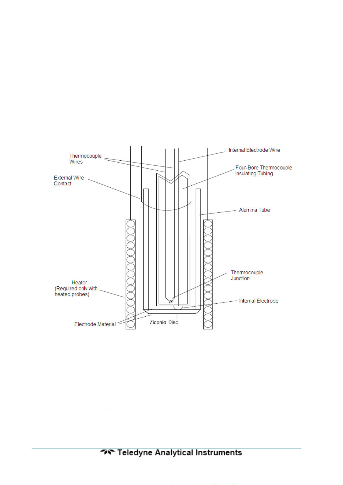
2.1 THE ZIRCONIA SENSOR
The transmitter input is provided for a solid electrolyte oxygen probe, which
contains a zirconia element and thermocouple. The probe is designed to be inserted into
a boiler or furnace exit gas flue or similar process. A 1234 sensor is designed to be
installed outside of the flue or process. Sampling lines and filters are not required for insitu probes but they are required for 1234 sensors. When a sampling line is required, the
sample flows to the sensor under process pressure in most applications. In applications
where the process pressure is negative or neutral, a suction pump will be required. A
reference air pump is provided in the 9060 oxygen Analyser. The internal construction of a
probe or sensor is shown as follows.
Schematic View of a Zirconia Sensor Assembly
The heater control in the 9060 Analyser consists of a time proportioning
temperature controller and solid state relay so that the thermocouple junction is controlled
to over 700°C (1300°F). Probes operating in a combustion environment above 650°C
(1200°F) do not require a heater. When exposed to different oxygen partial pressures at
the outside and inside of the sensor, an EMF (E) is developed which obeys the Nernst
equation:
E (millivolts) =
RT
4F
loge
(PO2) INSIDE
⎛
⎜
(PO2) OUTSIDE
⎝
⎞
⎟
⎠
Where T is the temperature (K) at the disc (>650°C (1200°F)), R is the gas constant, F is
the Faraday constant and (PO2) INSIDE and (PO2 ) OUTSIDE are the oxygen partial
19
19

9060-Zirconia Analyser
pressures at the inner and outer electrodes, respectively, with the higher oxygen partial
pressure electrode being positive.
If dry air at atmospheric pressure, (21 % oxygen) is used as a reference gas at the inner
electrode, the following equations are obtained:
E (millivolts) = 2.154 x 10
-2
T loge
(PO2) OUTSIDE
Transposing this equation
(%O2) OUTSIDE (ATM) = 0.21 EXP
The 9060 Analyser solves this equation which is valid above 650°C (1200°F). The probe
heater, or the process maintains the sensor temperature at this level.
2.2 THE OXYGEN PROBE OR SENSOR
The probe assembly provides a means of exposing the zirconia sensor to the
atmosphere to be measured with sensor, thermocouple and heater wires connected via
the transmitter lead. Reference air is fed via the plug for unheated probes and via a
separate gas thread connection for heated probes.
Connections are provided on probes for an in-situ gas calibration check. A
cleaning purge of air can be admitted via the calibration gas check entry. The outer
sheath of probes can be metal or ceramic, depending on the application. Calibration
check can be achieved on 1234 sensors using a three way solenoid which blocks the
sample and at the same time admits a calibration check gas to the sensor. Purging a
probe for any dust build up can be achieved in the same way.
In-situ zirconia oxygen probes will give a lower oxygen reading than a sampled
gas measurement on a chromatograph or paramagnetic transmitter because the flue gas
contains a significant level of water vapour and a sampling system removes the water
vapour through condensation. The oxygen content then appears as a higher percentage
of the remaining gas. For example: If the gas contained five parts oxygen and fifteen
parts moisture, removing the moisture would leave the oxygen at 5.88%. This phenomena
will depend on the fuel and the completeness of combustion. They are common to all insitu oxygen sensors.
2.3 THE ANALYSER
The top line of the transmitter display will read oxygen in either % or ppm.
The 9060 Analyser is a transmitter with two 4 to 20 mA outputs. One output is linear
oxygen with selectable span. The second output can be selected as oxygen deficiency,
combustibles, auxiliary temperature, reducing oxygen, percent carbon dioxide, sensor
EMF or a logarithmic oxygen range. Four alarm relays are provided. Refer to the sections
4.2 and 4.3 for more details.
The 9060 Analyser is designed to operate with either one or two heated or unheated,
zirconia probes or sensors in one process. If two sensors are being used, the transmitter
can average the two oxygen signals, alarm when there is a high difference, transmit and
display the average and/or individual oxygen signals.
0.21
-46.421E
T

9060-Zirconia Analyser
If heated probes are being used, the transmitter will maintain the temperature of the
sensor(s) to over 700°C (1300°F). If the flue gas temperature is above 850°C (1560°F),
the probe heater will cut out completely and the process will provide probe heating. The
transmitter solves the Nernst equation and will provide accurate oxygen measurements up
to 1500°C (2730°F), although most probes are suitable only to 1400°C (2250°F). 1231
heated probes are limited to 900°C (1650°F).
2.4 ALARMS
Refer to OPERATOR FUNCTIONS Section 4 for details on alarm functions.
2.5 HEATER
CAUTION
The probe or sensor heater is supplied with mains voltage. This supply has electrical shock danger to
maintenance personnel. Always isolate the transmitter before working with the probe or sensor.
The EARTH wire (green) from the probe/sensor must always be connected to earth.
The heater is supplied from the mains power directly, and the temperature is controlled
initially at over 700°C (1300°F) after turn on.
2.6 APPLICATIONS WHERE SENSING POINT IS NOT AT ATMOSPHERIC
PRESSURE
To apply the 9060 Analyser to processes that have pressure at the point of
measurement significantly above or below atmospheric pressure, then compensation must
be applied. (Refer to Set-up Steps 37 and 38 in Section 5.5). If two probes are being
used, they must be close to the same pressure.
If the process pressure is not constant, it can be measured by a pressure transducer
and fed into the oxygen transmitter as a 4-20mA signal. The pressure compensation will
then change the oxygen reading according to the current process pressure.
2.7 SENSOR IMPEDANCE
The zirconia sensor impedance is a basic measurement of the reliability of the
oxygen reading. A probe or sensor with a high impedance reading will eventually produce
erroneous signals. The transmitter checks the zirconia sensor impedance every 24 hours
and if the impedance is above the maximum level for a specific temperature then the
impedance alarm (Sensor Fail) will be activated. Typical sensor impedance is 1 KΩ to 8
KΩ at 720°C (1320°F).
The impedance measurement can be updated manually whenever the sensor is over
700°C (1290°F) by pressing the “AUTOCAL” button while in “RUN” mode. The “Z” will
appear in the top RH corner of the display for 3 seconds to confirm the measurement.
2.8 AUTO CALIBRATION - ELECTRONICS
The transmitter input section is self-calibrating. There are no adjustments. The
analog to digital converter input stages are checked against a precision reference source
and calibrated once every three seconds. Should the input electronics drift slightly then
the drift will be automatically compensated for within the microprocessor. If the calibration
21
21

9060-Zirconia Analyser
factors are found to be have been changed more than expected, an ‘ADC Warning’ alarm
is generated. If a large error occurs due to an electronic fault then an ‘ADC CAL FAIL’
alarm will occur.
A one-off calibration procedure of the precision reference sources should never need
to be repeated for the instrument life unless the instrument has been repaired. For a
description of the calibration procedure, refer to ‘Setting Up The transmitter’ Section 5.5,
items 7, 8 9 and 10.
The digital to analog converters or output section of the transmitter are tested for
accuracy when the ‘AUTOCAL’ button is pressed, and when the transmitter goes through
the start up procedure. If the output calibration factors are found to have changed more
than expected, the ‘DAC Warning’ alarm will occur. If either output has a fault, the ‘DAC
CAL FAIL’ alarm will occur. The D/A sections are re-calibrated by pressing the ‘AUTO
CAL’ button on the keyboard while in 'SET-UP' mode. Each of the output channels have
three menu items which provide manual calibration (set-up 13 to 18). If manual is selected
in set-up 13 or 16, the ‘AUTO CAL’ will be skipped and the manual calibration factors will
be retained. See section 5.5 set-up 13, and section 6.3 for more details.
All output signals will drop to 0 mA for one-second period. It is suggested that a D/A
re-calibration be performed after the instrument has stabilised, approximately 30 minutes
after first switching on and after Setting Up The transmitter Section 5.5, items 6, 7, 8 and 9
have been completed, and then annually.
2.9 MANUAL CALIBRATION - PROBES
Calibration of the probe generally only requires the Sensor Offset to be set. See
Section 5.5.11 for more details. If the offset for a sensor is not set the error will generally
be less than 5% of the actual oxygen reading. By setting the offset the error will be less
than 1% of the oxygen actual reading.
If a probe made by a manufacturer other than Teledyne Controls is used on the
Teledyne transmitter, and/or improved accuracy is required at process levels of oxygen
(well away from 20.9%) the “Low Oxygen Calibration” trim factors can be entered. (See
also Section 5.5.90)
To manually set the “Low Oxygen Calibration” first set the Sensor Offset, then the “Low
Oxygen Calibration”.
1. To check a probe offset on site, the probe must be sensing air, with reference air,
and allowed to settle at the probe operating temperature for 30 minutes. Read the
offset in ‘RUN’ mode in millivolts on the lower line. Offset errors can occur if the
sensor does not have some air passing over it. A gentle flow (<0.5 l/min) of air in
the calibration check port can be provided by a reference air pump or similar. The
best results will be obtained if the probe is removed from the process. For heated
probes, if the combustion appliance is not operational and the probe heater is
interlocked with the ‘BURNER ON’ signal, the ‘BURNER BYPASS’ switch should be
set to ‘ON to power the probe heater after removing the probe from the flue.
9060-Zirconia Analyser
CAUTION DANGER
Return the ‘BURNER BYPASS’ switch to normal (off) before installing the probe in the flue.
For unheated probes, the probe sensing tip must be raised to at least 650°C
(1200°F) with a portable furnace.
Determine the probe offset in ‘RUN’ mode. Select ‘Sensor EMF’ on the lower line.
With probe in air, stabilised at temperature for 30 minutes, read the ‘Sensor EMF’.
Switch back to ‘set-up’ mode and enter ‘Sensor Offset’ of equal value and the same
polarity.
eg. If the measured ’SENSOR OFFSET’ was -1.2 mV, enter -1.2 mV.
When reading the EMF offset, the flue pressure compensation must be set. If the
probe has been removed from the flue, set the flue pressure compensation set up to
“Fixed” in set-up 34, and the value to 0 in set-up step 38.
2. To set the probe “Low Oxygen Calibration”, replace the air purge in the calibration
check port with a flow of gas from a certified gas bottle. A flow of <1 l/min should be
used. After purging for 1 minute compare the oxygen reading to the oxygen
concentration on the bottle certificate. If the transmitter is reading lower than the
certified level, switch to the ‘set-up’ mode and raise the figure set-up 90 (for sensor
1). An increase of 1% in the set-up entry will increase the oxygen reading by about
3% of the actual oxygen reading.
NOTE: If the set-up items 90 and 91 are not available, see section 5.1.
It is very unusual to need to change the settings by more than 1%. If a setting
of more than 1% seems necessary, check for gas leaks, reference air flow or
excess calibration gas flow.
2.10 AUTO CALIBRATION CHECKING - PROBES
On-line automatic gas calibration check is not normally required. Where it is required
however, the probe can be checked for accuracy in-situ and on-line. Solenoid valves can
admit up to two calibrated gas mixtures into the probe via solenoid valves under
microprocessor control on a timed basis. For details on installation refer Section 3.11. For
details on setting up this facility refer to Set-up steps 57 to 69 in Section 5.5.
During probe auto calibration checking, the transmitter output will freeze and remain
frozen for a further adjustable period, allowing the probe time to recover and continue
reading the flue gas oxygen level.
Calibration check gases may be manually admitted by pressing the ‘CAL’ buttons on
the keyboard while in ‘RUN’ mode. The transmitter output is frozen during the pressing of
these buttons and immediately becomes active when the button is released. If calibration
gas checking is enabled in the Set-up menu for either gas, an automatic gas cycle can be
started by pressing the ‘CAL’ buttons in RUN mode. Pressing any other button can
terminate the cycle.
23
23

9060-Zirconia Analyser
2.11 AUTO PURGE
blocked. An automatic purge cycle can be set up so that a blast of air, maximum 100 kPa
(14.5 psi), will automatically back-flush the probe filter on a timed basis. Refer to Set-up
steps 52 to 56 in Section 5.5. A purge pressure switch will sense if there is insufficient
flow to clear the filter during the purge cycle. In this case a ‘PROBE FILTER’ alarm will
occur. The probe can be manually purged from the keyboard while in ‘RUN’ mode. The
transmitter output is not frozen during or after the pressing of this button.
solenoid but separate pressure regulators and pressure switches (See section 3.11)
2.12 RS 485 NETWORK (MODBUS™) AND RS 232C PORT
The serial port has two functions. -
It can be configured to connect up to 31 transmitters together on a MODBUS™ RS485
It can be used to log the transmitter readings by connecting the transmitter to a printer,
2.13 AUXILIARY TEMPERATURE THERMOCOUPLE
A flue thermocouple must be connected to the AUX thermocouple input when
combustibles display is required.
The AUX thermocouple may also be used to monitor and display any process
temperature.
2.14 WATCHDOG TIMER
second period, (ie. fails to run its normal program). The microprocessor will then be reset
up to three times until normal operation is resumed. Reset cycles are displayed by the
POWER light on the keyboard. A steady ‘ON’ light indicates normal operation. If the
program has not resumed normal operation after three attempts to reset, the common
alarm relay will be activated. The reset function will continue repeatedly after the alarm. If
a successful reset is achieved, the alarm will be cancelled and the transmitter will continue
to run normally.
In oil and coal fired plants, it is possible for the probe sensing filter to become
If two probes are being used, the two probes could be driven by a common
network. Each individual transmitter can be interrogated by a computer or PLC. The
values of oxygen, sensor EMF, sensor temperature, sensor impedance for both oxygen
sensors (if two sensors are being used on one transmitter) can be read over the
network. The alarms status can also be checked over the network. For the connection
details, see Section 3.15 and Appendix 6.
a data logger, or any computer using an RS232-C com port.
When it is to be used to log the transmitter readings, use set-up step 82 to selected the
items to be sent to the data logger. The log period may be selected in set-up step 83,
and the baud rate may be set in set-up step 84. Alarms, including the time they
occurred, will be transmitted to the printer and computer whenever they are first
initiated, accepted and cleared. The protocol for the serial port is eight data bits, one
stop bit, no parity.
The watchdog timer is started if the microprocessor fails to pulse it within any one-

9060-Zirconia Analyser
2.15 BACK-UP BATTERY
The transmitter’s RAM and real-time clock are backed up by a lithium battery in the event
of power failure. All set-up variables are saved and the clock is kept running for
approximately ten years with the power off. The battery module should be replaced every
8 years. (It is the battery shaped device clipped in a socket labelled M1.)
25
25

9060-Zirconia Analyser
INSTALLING & COMMISSIONING
3
SECTION
NUMBER INSTALLATION
3.1 MOUNTING THE TRANSMITTER
3.2a INSTALLING AN OXYGEN PROBE
3.2b INSTALLING A 1234 OXYGEN SENSOR
3.3 INSTALLING THE AUXILIARY THERMOCOUPLE
3.4 SHIELD CONNECTIONS
3.5 ELECTRICAL CONNECTIONS
3.6 HEATER INTERLOCK RELAYS
3.7a CONNECTING AN OXYGEN PROBE CABLE
3.7b CONNECTING A 1234 SENSOR CABLE
3.8 CONNECTING THE AUXILIARY THERMOCOUPLE (OPTIONAL)
3.9 CONNECTING THE OUTPUT CHANNELS
3.10 CONNECTING THE ALARMS
3.11 CONNECTING THE AUTOMATIC PURGE & CALIBRATION CHECK SYSTEM
3.12 CONNECTING REFERENCE AIR
3.13 CONNECTING THE DUAL FUEL INPUT
3.14 CONNECTING THE PRINTER
3.15 CONNECTING THE TRANSMITTER TO A MODBUS™ NETWORK
COMMISSIONING
3.16 CONNECTING POWER
3.17 COMMISSIONING - SET-UP MODE
3.18 COMMISSIONING - RUN MODE
3.19 BURNER BY-PASS SWITCH
3.20 CHECKING ALARMS
3.21 PROBE CALIBRATION CHECK
3.22 FILTER PURGE SET-UP PROCEDURE
3.23 CALIBRATION CHECK GAS SET-UP PROCEDURE
3.24 DUST IN THE FLUE GAS
3.25 STRATIFICATION
3.26 CONNECTING A PRESSURE TRANSDUCER
9060-Zirconia Analyser
INSTALLATION
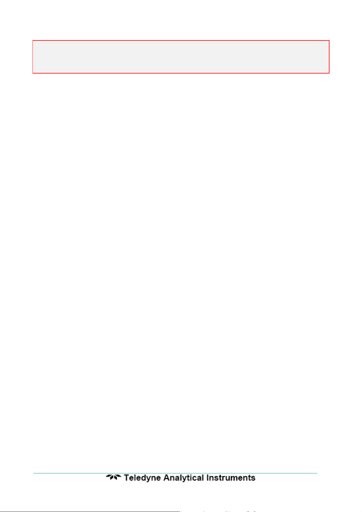
3.1 MOUNTING THE TRANSMITTER
Surface mount the transmitter case on to a flat surface or bracket, using the four
mounting brackets provided. Make sure the ambient temperature is below 50°C, and that
the radiated heat from furnaces and boilers is kept to a minimum.
Case Mounting Dimensions
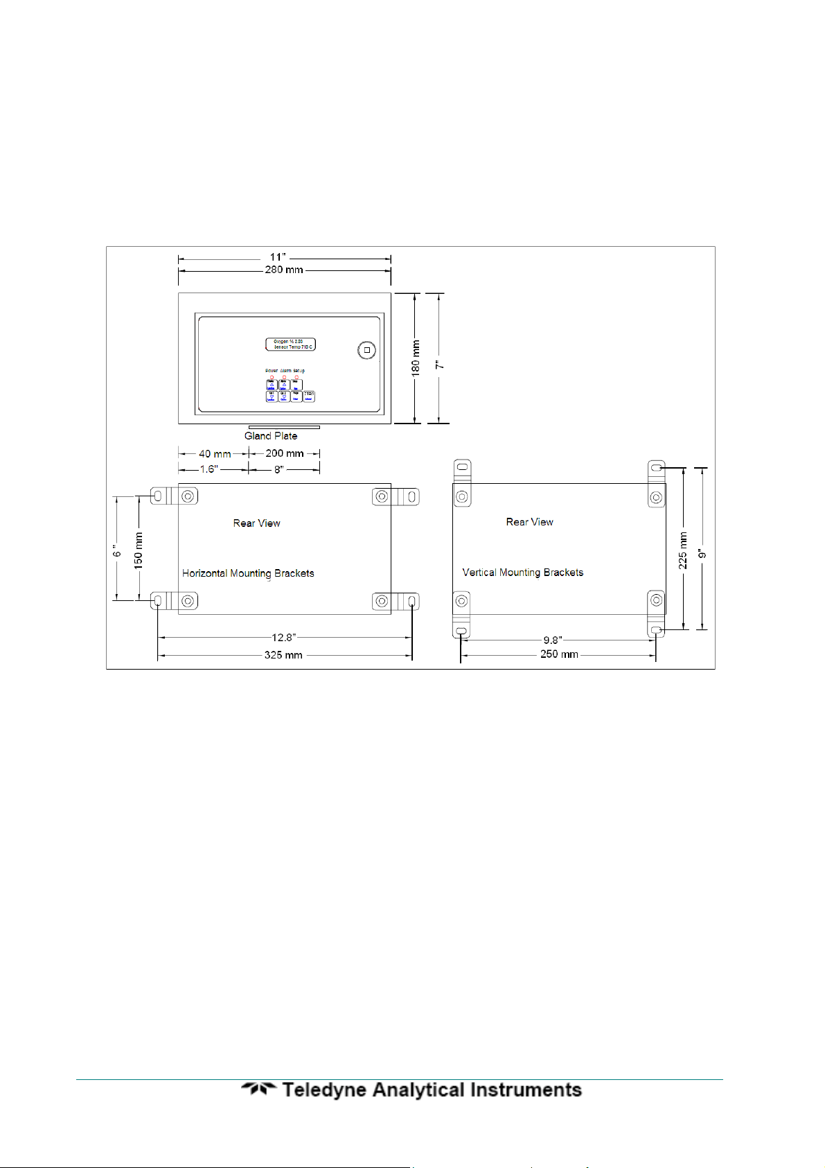
3.2a INSTALLING A 1231 OXYGEN PROBE
Weld a BSP or NPT socket to the flue in a suitable position for flue gas sensing.
For the correct size of socket refer to probe data in Section 1. The closer to the source of
combustion the smaller will be sensing lag time, allowing better control.
The probe has a typical response time of less than four seconds, so most of the
delay time is normally the transit time of the gas from the point of combustion to the point
of sensing.
Probes can be mounted at any angle. If there are any particulates in the flue gas,
a filter can be omitted by pointing the probe vertically downwards. Otherwise the filters
may have to be replaced periodically.
If installing a probe into a hot environment, slide the probe in slowly to avoid
thermal shock to the internal ceramic parts. If the flue gas is 1000°C (1830°F), it should
27
27
9060-Zirconia Analyser
take approximately five minutes to install a 500 mm (20”) probe, moving it in about 50 mm
(2”) steps.
Oxygen Probe Mounting
CAUTION
It is important that there is no air in leakage upstream of the oxygen sensing point,
otherwise there will be a high oxygen reading.
If the probe is to be installed on a bend in the flue, it is best located on the outer
circumference of the bend to avoid dead pockets of flue gas flow. While the standard
1231 probe with a ‘U’ length of 250 mm (10”) will suit most low temperature flue
applications, it is occasionally necessary to have a longer probe with the sensing tip in the
center of the flue gas stream.
Although it is rare, occasionally a probe may sense oxygen vastly differently from the
average reading in the flue gas. If it occurs, then the probe should be moved, or a longer
probe installed. This phenomena is normally caused by stratification of the flue gas.
9060-Zirconia Analyser
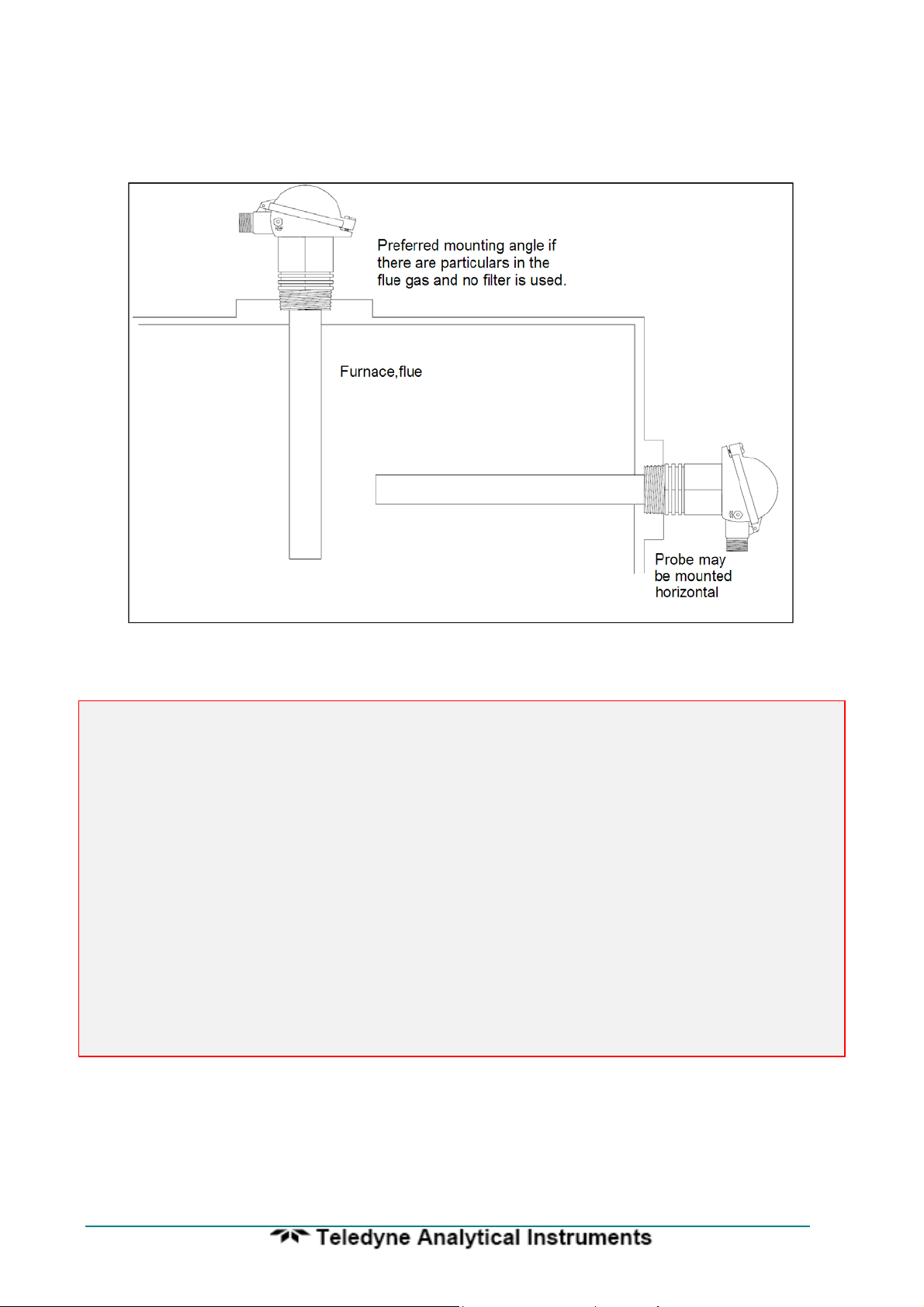
3.2b INSTALLING A 1234 OXYGEN SENSOR
Mounting - Screw the 1234 sensor to a wall or similar surface with the piping
connections at the bottom.
1234 Sensor Mounting Dimensions
29
29

9060-Zirconia Analyser
Sample Piping - Connect the gas sample piping to the “sample in” port. If the process,
boiler, kiln or furnace has a positive pressure, no suction will be required. If the sample is
under a negative pressure, connect a pump to the “inlet” port as shown below. The flow
rate should be within the range of 1 to 5 litres/minute (120 to 600 scfm).
3.3 INSTALLING THE AUXILIARY THERMOCOUPLE
Weld a 1/2 inch BSP mounting socket to the flue within about 300 mm (12”), and
upstream of the oxygen probe. The thermocouple should be of similar length to the
oxygen probe to prevent flue temperature distribution errors.
3.4 SHIELD CONNECTIONS
All external wiring to the 9060 Analyser should be shielded. Do not connect shields
at the field end. Simply clip off and insulate. An extra terminal strip may be required to
connect all shields together. This should be supplied by the installer.
Flue
Gas
Upward sloping
sample line 3/8”
stainless steel
Sampling
Probe
Flowmeter
1234
Sensor
Optional vent to
atmospherre
Optional return
to flue
1/4" Stainless Steel Tube
Dry
Process
Gas
1234
Sensor
Vent or return
to process
 Loading...