

Page 1

Oxygen Monitor System
T eledyne Analytical Instruments
3220
Oxygen Monitor System
P/N: M73831
ECO# 01-0267
10/05/01
Teledyne Analytical Instruments i
Page 2
Model 3220
Instruction Manual
Model 3220
Multi-Channel
Oxygen
Monitor
DANGER
Toxic gases and or flammable liquids may be present in this monitoring
system.
Personal protective equipment may be required when servicing this instrument.
Hazardous voltages exist on certain components internally which may persist
for a time even after the power is turned off and disconnected.
Only authorized personnel should conduct maintenance and/or servicing.
Before conducting any maintenance or servicing, consult with authorized
supervisor/manager.
Teledyne Analytical Instruments ii
Page 3

Oxygen Monitor System
Teledyne Analytical Instruments iii
Page 4

Model 3220
Copyright © 2001 TELEDYNE Analytical Instruments
All Rights Reserved. No part of this manual may be reproduced, transmitted, transcribed,
stored in a retrieval system, or translated into any other language or computer language in
whole or in part, in any form or by any means, whether it be electronic, mechanical,
magnetic, optical, manual, or otherwise, without the prior written consent of Teledyne
Analytical Instruments, 16830 Chestnut Street, City of Industry, CA 91749-1580.
Warranty
This equipment is sold subject to the mutual agreement that it is warranted by us free
from defects of material and of construction, and that our liability shall be limited to
replacing or repairing at our factory (without charge, except for transportation), or at
customer plant at our option, any material or construction in which defects become
apparent within one year from the date of shipment, except in cases where quotations or
acknowledgments provide for a shorter period. Components manufactured by others bear
the warranty of their manufacturer. This warranty does not cover defects caused by wear,
accident, misuse, neglect or repairs other than those performed by Teledyne or an
authorized service center. We assume no liability for direct or indirect damages of any
kind and the purchaser by the acceptance of the equipment will assume all liability for
any damage which may result from its use or misuse.
We reserve the right to employ any suitable material in the manufacture of our apparatus,
and to make any alterations in the dimensions, shape or weight of any parts, in so far as
such alterations do not adversely affect our warranty.
Important Notice
This instrument provides measurement readings to its user, and serves as a tool by which
valuable data can be gathered. The information provided by the instrument may assist the
user in eliminating potential hazards caused by his process; however, it is essential that
all personnel involved in the use of the instrument or its interface, with the process being
measured, be properly trained in the process itself, as well as all instrumentation related
to it.
The safety of personnel is ultimately the responsibility of those who control process
conditions. While this instrument may be able to provide early warning of imminent
danger, it has no control over process conditions, and it can be misused. In particular, any
alarm or control systems installed must be tested and understood, both as to how they
operate and as to how they can be defeated. Any safeguards required such as locks,
labels, or redundancy, must be provided by the user or specifically requested of Teledyne
at the time the order is placed.
Therefore, the purchaser must be aware of the hazardous process conditions. The
purchaser is responsible for the training of personnel, for providing hazard warning
methods and instrumentation per the appropriate standards, and for ensuring that hazard
warning devices and instrumentation are maintained and operated properly.
Teledyne Analytical Instruments (TAI) cannot accept responsibility for conditions
beyond its knowledge and control. No statement expressed or implied by this document
or any information disseminated by the manufacturer or its agents, is to be construed as a
warranty of adequate safety control under the user’s process conditions.
Teledyne Analytical Instruments iv
Page 5

Oxygen Monitor System
Specific Model Information
The Instrument for which this manual was supplied may incorporate
one or more options not present in the standard instrument. If such options
were specified at the time of purchase, an addendum describing the unique
features and specifics of the included options will be included with this
manual. Please check the frontmatter of this manual to see if an addendum
has been included.
Instrument Serial Number: _______________________
Teledyne Analytical Instruments v
Page 6

Model 3220
Important Notice
The Model 3220 is a safety monitor, however, it is the responsibility
of the user to establish whether or not the total system of instrument,
environment, alarm components, and any other relevant devices actually
will assure safety under the particular circumstances of use.
Location of the equipment and sensors that will insure proper
operation is the responsibility of the user.
The safety checklist outlined below is only a guide. It is up to the user
to establish practical safety precautions given his/her own specific
circumstances. It is vital that the operator understand and test the
operation of the total system.
Safety Checklist
Verify that the instrument is powered correctly.
Verify that the instrument works properly (all functions).
Verify that alarm conditions produce the intended results.
Verify that unauthorized personnel cannot tamper with the
instrument or its auxiliary equipment.
Institute routine test/calibration procedures.
Identify and handle any potential problems in sampling or location.
Train all operators to understand all operations and functions of the
analyzer and the system.
Identify and handle any environmental or other influences that
could affect the operation of the instrument.
Teledyne Analytical Instruments vi
Page 7
Oxygen Monitor System
Safety Messages
Your safety and the safety of others is very important. We have
provided many important safety messages in this manual. Please read these
messages carefully.
A safety message alerts you to potential hazards that could hurt you or
others. Each safety message is associated with a safety alert symbol. These
symbols are found in the manual and inside the instrument. The definition
of these symbols is described below:
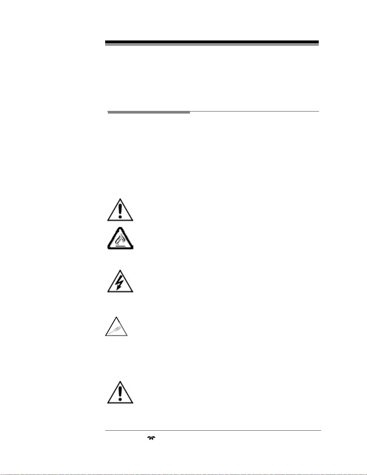
GENERAL WARNING/CAUTION: Refer to the instructions
for details on the specific danger. These cautions warn of
specific procedures which if not followed could cause bodily
Injury and/or damage the instrument.
CAUTION: HOT SURFACE WARNING: This warning is specific
to heated components within the instrument. Failure to heed the
warning could result in serious burns to skin and underlying
tissue.
WARNING: ELECTRICAL SHOCK HAZARD: Dangerous voltages
appear within this instrument. This warning is specific to an
electrical hazard existing at or nearby the component or
procedure under discussion. Failure to heed this warning could
result in injury and/or death from electrocution.
Technician Symbol: All operations marked with this symbol are
to be performed by qualified maintenance personnel only.
NOTE: Additional information and comments regarding a
specific component or procedure are highlighted in the form of a
note.
CAUTION: THE ANALYZER SHOULD ONLY BE USED FOR THE
PURPOSE AND IN THE MANNER DESCRIBED IN THIS
MANUAL.
IF YOU USE THE ANALYZER IN A MANNER OTHER
THAN THAT FOR WHICH IT WAS INTENDED,
UNPREDICTABLE BEHAVIOR COULD RESULT
Teledyne Analytical Instruments vii
Page 8

Model 3220
POSSIBLY ACCOMPANIED WITH HAZARDOUS
CONSEQUENCES.
This manual provides information designed to guide you through the
installation, calibration and operation of your new analyzer. Please read
this manual and keep it available.
Occasionally, some instruments are customized for a particular
application or features and/or options added per customer requests. Please
check the front of this manual for any additional information in the form of
an Addendum which discusses specific information, procedures, cautions
and warnings that may be peculiar to your instrument.
Manuals do get lost. Additional manuals can be obtained from
Teledyne at the address given in the Appendix. Some of our manuals are
available in electronic form via the internet. Please visit our website at:
www.teledyne-ai.com.
Teledyne Analytical Instruments viii
Page 9

Oxygen Monitor System
Table of Contents
Important Notice...........................................................................vi
Safety Checklist vi
Safety Messages .........................................................................vii
Table of Contents.........................................................................ix
List of Figures..............................................................................xii
List of Tables..............................................................................xiii
Introduction ...................................................................................1
1.1 Overview 1
1.2 Description 1
1.2.1 System Chassis (19” Rack) 2
1.2.2 Control Unit 2
1.2.3 Channel Modules 2
1.2.3.1 Main Features of the Channel Module 2
1.2.4 Remote Probe Assemblies 4
Operational Theory .......................................................................6
2.1 Introduction 6
2.2 System Chassis 6
2.3 Control Unit 6
2.4 Channel Module 8
2.5 Micro-fuel Cell 10
2.5.1 Anatomy of a Micro-Fuel Cell 10
2.5.2 Electrochemical Reactions 12
2.5.3 The Effect of Pressure 12
2.5.4 Calibration Characteristics 13
2.5.4 Micro-Fuel Cell “Class” 14
2.5.4.1 Class A-3 Cell 14
2.5.4.2 Class A-5 Cell 14
2.5.4.3 Class B-1 Cell 14
Teledyne Analytical Instruments ix
Page 10

Model 3220
2.5.4.4 Class B-3 Cell 14
2.5.4.5 Class C-3 Cell 15
2.5.4.6 Hydrogen and/or Helium Service 15
Installation...................................................................................16
3.1 Unpacking the Analyzer 16
3.2 System Chassis 16
3.2.1 Location 16
3.2.2 Power 16
3.3 Electrical Connections 17
3.4 Probe Assemblies 17
3.5 Micro-Fuel Cell 18
3.6 Control Unit 19
3.6.1 Control Unit Fuses 19
3.6.2 Control Unit Jumper Settings 20
3.7 Channel Modules 22
3.7.1 Removing the Channel Module Cover 22
3.7.2 Changing the Fuse 22
3.7.3 Configuring the Internal Jumper Connections 23
Operation.....................................................................................25
4.1 Introduction 25
4.2 Control Unit Operation 25
4.2.1 System Power Switch and LED 25
4.2.2 Audible Alarm Switch and Bypass LED 25
4.2.3 Fuses 26
4.2.4 RS485 Port 26
4.3 Channel Module Front Panel Controls and Indicators 26
4.4 Calibration Procedures 30
4.4.1 Zero Calibrating a Single Sensor Channel Module 30
4.4.2 Span Calibrating a Channel Module 31
4.4.5 Using the “1MAN” Calibration Option 31
4.4.5.1 Zero and Span Calibrating a Channel Module 31
4.5 Alarm Configuration Procedures 32
4.5.1 Defining the Setpoint for Alarm 1 and Alarm 2 32
Teledyne Analytical Instruments x
Page 11

Oxygen Monitor System
4.5.2 Configuring Alarm Relay Settings 33
4.5.2.1 Setting the Fail-safe or Non-Fail-safe Mode 33
4.5.2.2 Setting the Latching or Non-Latching Mode 33
4.5.2.3 Setting Alarms to Hi or Lo 34
4.6 Setting the ID Code 34
4.7 Enabling/Disabling the Pass Code 35
4.8 Range Set-Up 36
4.9 Cell Failure Set-Up 37
4.10 Routine Operation 38
4.11 FAIL Alarm Conditions 37
Failure and Error Codes..............................................................38
5.1 Failure Codes 38
5.2 Error Codes 38
Appendix......................................................................................40
A-1 Specifications 40
Recommended Spare Parts List 41
Drawing List 42
Index 45
Teledyne Analytical Instruments xi
Page 12

Model 3220
List of Figures
Figure 1-1: Model 3220 System......................................................1
Figure 1-2: Control Unit...................................................................2
Figure 1-3: The Channel Module..................................................... 3
Figure 2-1: Control Unit Front Panel................................................7
Figure 2-2: Control Unit Block Diagram...........................................7
Figure 2-3: Block Diagram of the Signal Processing Electronics.....9
Figure 2-4: Micro-fuel Cell.............................................................10
Figure 2-5: Cross Section of a Micro-fuel Cell...............................11
Figure 2-6: Characteristic Input/Output Curve for MFC.................13
Figure 3-1: Oxygen Probe Assembly.............................................18
Figure 3-2: Fuse Location .............................................................23
Figure 4-1: RS-485 Port on Control Unit .......................................26
Figure 4-2: Display Panel Configuration........................................29
Teledyne Analytical Instruments xii
Page 13

Oxygen Monitor System
List of Tables
Table 3-1: Control Unit Jumper Configuration...............................20
Table 3-2: Fail-safe/Non Fail-safe Alarm Configuration.................20
Table 3-3: External Alarm—Failsafe/Non-failsafe Configuration ...21
Table 3-4: External Alarm—Contact Closure.................................21
Table 3-5: External Alarm—Line Voltage to External Connection.21
Table 3-6: Channel Module Internal Jumper Settings ...................23
Table 3-7: RS-485 Jumper Settings..............................................24
Table 3-8: Jumper Settings for Channel Module Output ...............24
Teledyne Analytical Instruments xiii
Page 14

Model 3220
Teledyne Analytical Instruments xiv
Page 15
Oxygen Monitor System 1 Introduction
Introduction
1.1 Overview
The Teledyne Analytical Instruments (TAI) Model 3220 Oxygen
Monitor System is a multi-channel system that can be used for determining
the concentration of oxygen gas in an atmosphere at a number of remote
locations. The system provides alarm information when the oxygen
concentration exceeds user definable limits at any one or all of the remote
locations.
The oxygen gas content of the atmosphere is determined by a number
of remotely located sensors that may be strategically placed to monitor the
atmosphere surrounding their location.
The system is designed to provide indications of the state of each
sensor and to actuate individual external alarm indicators as well as alarms
common to all channels. The alarms are user-configurable.
1.2 Description
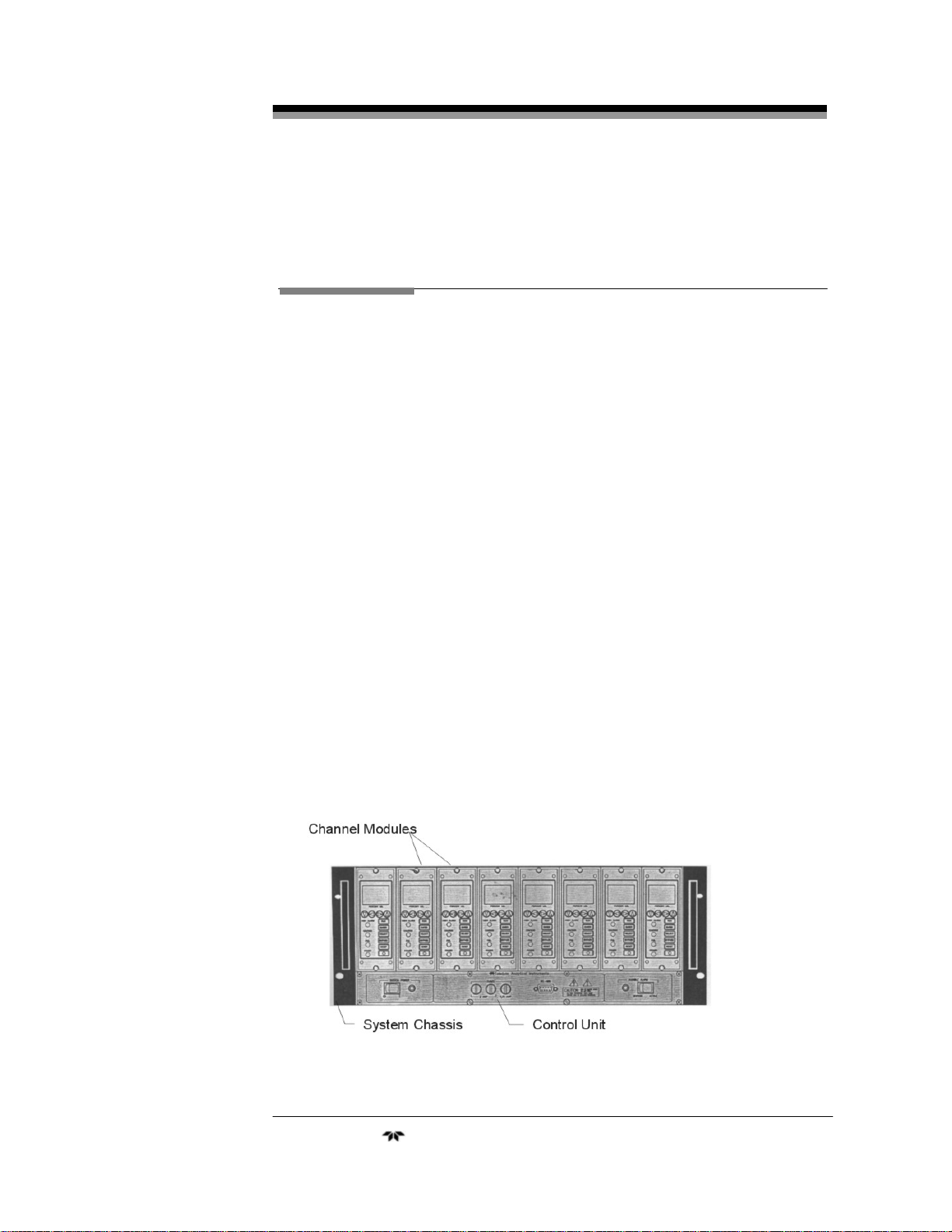
The 3220 system is comprised of a System Chassis, Control Unit,
Channel Modules, and Remote Probe Assemblies. Each System Chassis
contains one Control Unit and up to eight Channel Modules.
Figure 1-1: Model 3220 System
Teledyne Analytical Instruments 1
Page 16
1 Introduction Model 3220
1.2.1 System Chassis (19” Rack)
The System Chassis provides structural support and electrical
interconnection for the Control Unit and Channel Modules (up to eight
Channel Modules may be installed). The Channel Modules plug into the
sockets built into the System Chassis. Terminal strips at the rear of the
System Chassis provide for external electrical connections.
1.2.2 Control Unit
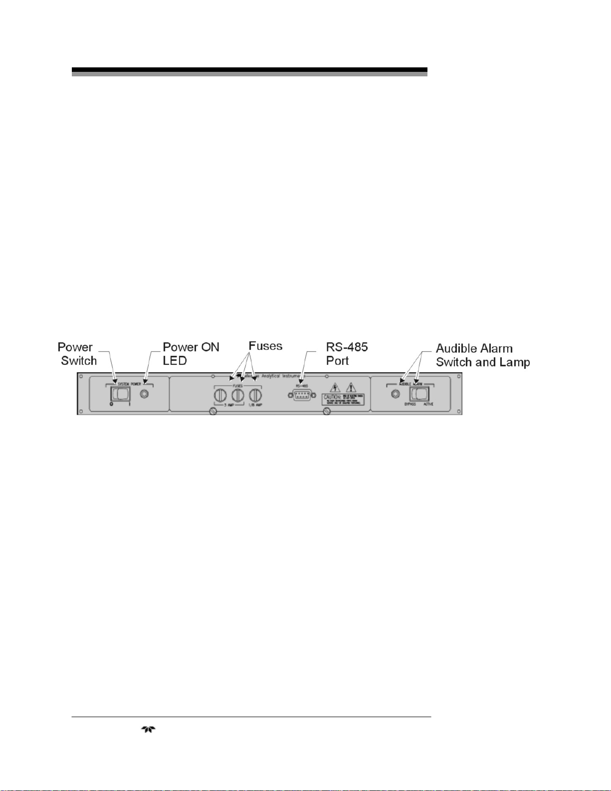
The Control Unit handles power distribution to the entire system. The
main power is controlled by a switch on the front panel and the system
fuses are accessible from the front. The Control Unit also contains common
alarm relays which indicate alarm conditions whenever any of the Channel
Modules alarm. The Control Unit is shown in Figure 1-2.
Figure 1-2: Control Unit
1.2.3 Channel Modules
Each Channel Module is a complete, self-contained instrument
including integral power supply and requires only external AC power
which it receives from the System Chassis socket. A channel is operational
when plugged into the System Chassis.
Because a Channel Module plugs into the Control Unit, channels can
easily be added to any control module with less than eight Channel
Modules even after installation to monitor additional locations. Channel
Modules in the same System Chassis may still be configured
independently. A Channel Module is shown in Figure 1-3.
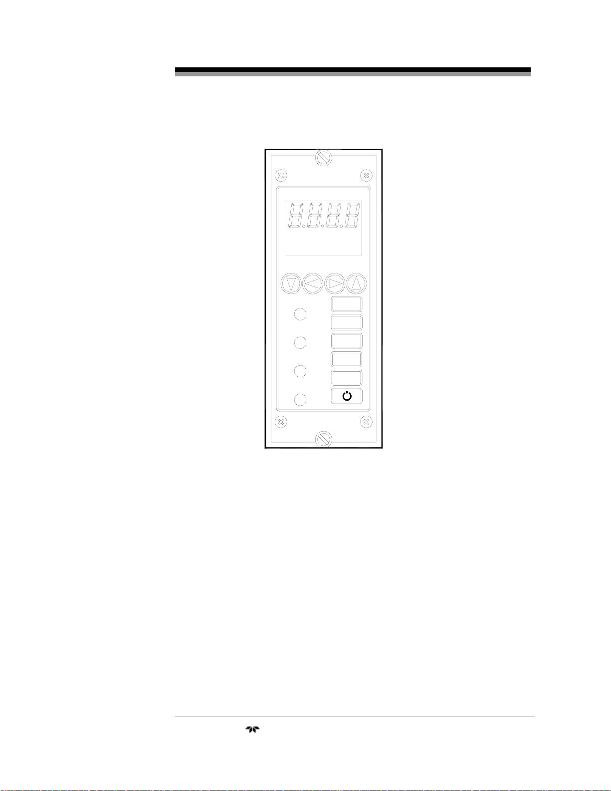
1.2.3.1 MAIN FEATURES OF THE CHANNEL MODULE
The main features of the Channel Module include:
• High resolution LCD display readout
• Drop-in replacement for Model 322 instruments
Teledyne Analytical Instruments 2
Page 17
Oxygen Monitor System 1 Introduction
ZERO SPAN 1MAN
R1 R2 A F CF
A1 L H N LCH N FS
A2 L H N LCH N FS
PERCENT OXYGEN
ALARM 1
ALARM 2
FAIL
POWER
RUN
ENTER
SELECT
BYPASS
RESET
Figure 1-3: The Channel Module
Teledyne Analytical Instruments 3
Page 18

1 Introduction Model 3220
• 1MAN calibration capability
• Membrane switch control
• Microprocessor based electronics
• Two concentration alarms with adjustable set-points
• System failure alarm
• User-friendly touch key controls
• Passcode protection
• Failure codes and testpoints
• Two selectable analog outputs (0-10V DC or negative ground
4-20 mA DC
• Compact and versatile design: small footprint with accessible
internal PCBs
1.2.4 Remote Probe Assemblies
Each Control Unit allows for up to eight remote probe assemblies.
These assemblies can be of standard configuration (see Probe Assembly
Outline Drawing in the drawing section of the Appendix) or special design
(if equipped, unique features are described in an included addendum to this
manual) depending on the application requirement. In either case, the
probes can be located almost any distance (up to 1000 ft or more!) from the
System Chassis.
Each probe assembly, when placed into service, will contain a Microfuel Cell, a temperature compensating thermistor and auxiliary sample
handling equipment (if required). The Micro-fuel Cell is packaged in a gas
barrier bag and should not be installed in the probe assembly until after
installation of all other components of the system has been accomplished.
Temperature compensation is affected over the range 0-50°C and to an
accuracy of ±5% of full scale. If other than diffusion sampling is to be
employed, it is assumed that the sample gas will be brought to ambient
temperature. The cell and thermistor must always be kept at the same
temperature, otherwise the resultant differential temperature of these two
components can cause inaccuracies in excess of those specified.
If the ambient temperature at the probe assembly can drop below 0°C
(32°F), auxiliary heating should be employed. Normally this condition is
noted at the time of purchase and specially configured probes will have
been provided. TAI can provide sampling probes to cope with most all
Teledyne Analytical Instruments 4
Page 19

Oxygen Monitor System 1 Introduction
sampling problems encountered in virtually any application. Please refer to
any included addenda for additional information regarding custom probes.
Teledyne Analytical Instruments 5
Page 20

2 Operational Theory Model 3220
Operational Theory
2.1 Introduction
The Model 3220 combustible gas analyzer is composed of four
components:
1. System Chassis
2. Control Unit
3. Channel Modules
4. Micro-fuel Cell
The System Chassis provides structural support and electrical
interconnection for a Control Unit and up to eight Channel Modules. Each
Channel Module can monitor one sensor.
2.2 System Chassis
All electrical connections are located on the rear of the system
chassis. There are nine terminal strips, one for each of the Channel
Modules and one for the Control Module.
2.3 Control Unit
The Control Unit provides control of electrical power to the
channel module, audio alarms and external alarms through the common
alarm relays. The front panel of the Control Unit is shown if Figure 2-1
Alarm signals from any Channel Module trigger the corresponding
relays in the Control Unit. For example, “alarm 1” signals from any channel
trigger the “alarm 1” relay in the system control module. There are three
such relays in the Control Unit, one each for alarm 1, alarm 2, and failure
alarms. The failure alarm relay in the Control Unit is operated “fail-safe”;
however, the gas level alarm relays can be optionally connected for operation
in the “non fail-safe” mode by setting the configuration jumpers as indicated
in the installation section 3.6.2. Each of these relays provides SPDT contacts
for operation of external devices.
Teledyne Analytical Instruments 6
Page 21

Oxygen Monitor System 2 Operational Theory
Figure 2-1: Control Unit Front Panel
An audible alarm is actuated when any alarm state occurs. This
audible alarm may be disconnected by switching the AUDIBLE
ALARM control switch to the BYPASSED position. When this is done,
the red lamp on the system module is illuminated as an indication that
the audible alarm is not functioning. A block diagram of the Control
Unit is shown in Figure 2-2.
The Control Unit is the power entry and distribution point. The
3220 system contains universal power supplies that operate on 100-240
VAC, 50/60Hz. The power switch on the Control Unit switches power
for the entire system. The line is protected by two 3 Amp fuses,
accessible from the front panel.
Figure 2-2: Control Unit Block Diagram
Teledyne Analytical Instruments 7
Page 22

2 Operational Theory Model 3220
A 1/8 A fuse is furnished for the electronic circuitry of the Control
Unit. The green power LED indicates that the Unit is ON.
Alarm switch S2 has two positions. Normally, the switch is set to
the ACTIVE position which provides for audible alarm when any of the
Channel Modules goes into the alarm state. When set to the BYPASS
position, the local audible alarm is turned off.
2.4 Channel Module
The Model 3220 Oxygen Gas Analyzer uses an Intel
Microcontroller with on-board RAM and ROM to control all signal
processing, input/output, and display functions for the analyzer. The
channel power is supplied from separate universal power supply
modules (100-240 VAC), designed to be compatible with most
international power sources. The power supply (triple outputs) supplies
the voltages for logic devices and analog circuitry.
A block diagram of the functional relationships of the Channel
Module is shown in Figure 2-3.
Teledyne Analytical Instruments 8
Page 23

Oxygen Monitor System 2 Operational Theory
Figure 2-3: Block Diagram of the Signal Processing Electronics
Teledyne Analytical Instruments 9
Page 24

2 Operational Theory Model 3220
2.5 Micro-fuel Cell
The oxygen sensor used in the Model 3220 Oxygen Monitor is a
Micro-fuel Cell designed and manufactured by Teledyne Analytical
Instruments. It is a sealed plastic disposable electrochemical transducer.
The active components of the Micro-Fuel Cell are a cathode, an
anode, and the 15% aqueous KOH electrolyte in which they are
immersed. The cell converts the energy from a chemical reaction into an
electrical current in an external electrical circuit. Its action is similar to
that of a battery.
There is, however, an important difference in the operation of a
battery as compared to the Micro-Fuel Cell. In the battery, all reactants
are stored within the cell, whereas in the Micro-Fuel Cell, one of the
reactants (oxygen) comes from outside the device as a constituent of the
gas being monitored or sampled. The Micro-Fuel Cell is therefore a
hybrid between a battery and a true fuel cell. (All of the reactants are
stored externally in a true fuel cell.)
2.5.1 Anatomy of a Micro-Fuel Cell
The Micro-Fuel Cell is a cylinder only 1 1/4 inches in diameter and 1
inch thick. It is made of extremely inert plastic, which can be placed
confidently in practically any environment or sample stream. It is
effectively sealed, although one end is permeable to oxygen in the
monitoring or sampling environment. The other end of the cell is a contact
plate consisting of two concentric foil rings. The rings mate with springloaded contacts in the sensor block assembly and provide the electrical
connection to the rest of the analyzer. Figure 2-1 illustrates the external
features.
Figure 2-4: Micro-fuel Cell
Teledyne Analytical Instruments 10
Page 25

Oxygen Monitor System 2 Operational Theory
Figure 2-5 illustrates a cross section of a Micro-fuel cell.
At the top end of the cell is a diffusion membrane of Teflon, whose
thickness is very accurately controlled. Beneath the diffusion membrane
lies the oxygen sensing element the cathode-with a surface area almost
2
4 cm
. The cathode has many perforations to ensure sufficient wetting of
the upper surface with electrolyte, and it is plated with an inert metal.
The anode structure is below the cathode. It is made of lead and has
a proprietary design which is meant to maximize the amount of metal
available for chemical reaction.
Figure 2-5: Cross Section of a Micro-fuel Cell
At the rear of the cell, just below the anode structure, is a flexible
membrane designed to accommodate the internal volume changes that
occur throughout the life of the cell. This flexibility assures that the
sensing membrane remains in its proper position, keeping the electrical
output constant. The entire space between the diffusion membrane,
above the cathode, and the flexible rear membrane, beneath the anode, is
filled with electrolyte. Cathode and anode are submerged in this
common pool. They each have a conductor connecting them to one of
the external contact rings on the contact plate, which is on the bottom of
the cell.
Teledyne Analytical Instruments 11
Page 26

2 Operational Theory Model 3220
2.5.2 Electrochemical Reactions
The sample gas diffuses through the Teflon membrane. Any
oxygen in the sample gas is reduced on the surface of the cathode by the
following half reaction:
O2 +2H2O + 4e- → 4OH- (cathode)
In this reaction, four electrons combine with one oxygen
molecule—in the presence of water from the electrolyte—to produce
four hydroxyl ions.
When the oxygen is reduced at the cathode, lead is simultaneously
oxidized at the anode by the following half reaction:
+2
Pb + 2OH- → Pb
+ H
O + 2e- (anode)
2
In this reaction, two electrons are transferred for each atom of lead
that is oxidized. Therefore it takes two of the above anode reactions to
balance one cathode reaction and transfer four electrons.
The electrons released at the surface of the anode flow to the cathode
surface when an external electrical path is provided. The current is
proportional to the amount of oxygen reaching the cathode. It is measured
and used to determine the oxygen concentration in the gas mixture.
The overall reaction for the fuel cell is the SUM of the half
reactions above, or:
2Pb + O2 → 2PbO
These reactions will hold as long as no gaseous components
capable of oxidizing lead—such as iodine, bromine, chlorine and
fluorine—are present in the sample.
The output of the fuel cell is limited by:
(1) the amount of oxygen in the cell at the time and
(2) the amount of stored anode material.
In the absence of oxygen, no current is generated.
2.5.3 The Effect of Pressure
In order to state the amount of oxygen present in the sample as a
percentage of the gas mixture, it is necessary that the sample diffuse into
the cell under constant pressure.
If the total pressure increases, the rate that oxygen reaches the
cathode through the diffusing membrane will also increase. The electron
Teledyne Analytical Instruments 12
Page 27

Oxygen Monitor System 2 Operational Theory
transfer, and therefore the external current, will increase, even though
the oxygen concentration of the sample has not changed. It is therefore
important that the sample pressure at the fuel cell (usually vent pressure)
remain constant between calibrations.
2.5.4 Calibration Characteristics
Given that the total pressure of the sample gas at the surface of the
Micro-fuel Cell input is constant, a convenient characteristic of the cell
is that the current produced in an external circuit is directly proportional
to the rate at which oxygen molecules reach the cathode. This rate is
directly proportional to the concentration of oxygen in the gaseous
mixture. In other words it has a linear characteristic curve, as shown in
Figure 2-6. Measuring circuits do not have to compensate for
nonlinearity.
In addition, since there is zero output in the absence oxygen, the characteristic curve has close to an absolute zero. In the percent ranges, the cell
itself does not need to be zeroed. In practical application zeroing is still used
to compensate for zero offsets in the electronics. (The electronics is zeroed
automatically when the instrument power is turned on.)
Figure 2-6: Characteristic Input/Output Curve for a Micro-fuel
Cell
Teledyne Analytical Instruments 13
Page 28

2 Operational Theory Model 3220
2.5.4 Micro-Fuel Cell “Class”
TAI manufactures Micro-Fuel Cells with a variety of characteristics
to give the best possible performance for any given sample conditions. A
few typical Micro-Fuel Cells are listed below with their typical use and
electrical specifications.
2.5.4.1 CLASS A-3 CELL
The class A-3 cell is for use in applications where it is exposed
continuously to carbon dioxide concentrations between 1% and 100% in
the monitoring environment for example in a flue gas monitoring
process.
Nominal output in air is 0.20 mA, and 90% response time is 45 sec.
Expected life in flue gas is 8 months. The warranted life of the A-3 cell
is 6 months.
NOTE: In instruments using the A-3 cell, special precaution must be
taken to protect the cell from prolonged exposure to high oxygen
concentrations such as ambient air.
2.5.4.2 CLASS A-5 CELL
The class A-5 cell is for use in applications where it is exposed
intermittently to carbon dioxide concentrations up to 100% in the sample
gas.
Nominal Output in air is 0.19 mA, and 90% response time is 45
sec. Expected life in a flue gas is 8 months and it is warranted for 6
months.
2.5.4.3 CLASS B-1 CELL
The class B-1 cell is for use in applications where it is exposed to
less than 0.1% of carbon dioxide, and where fast response is important.
Nominal output in air is 0.50 mA, and 90% response time is 7 sec.
Expected life in air is 8 months and it is warranted for 6 months.
2.5.4.4 CLASS B-3 CELL
The class B-3 cell is for use in applications where a slightly longer
response time is acceptable in order to have a longer cell life.
Nominal output in air is 0.30 mA, and 90% response time is 13 sec.
Expected life in air is 12 months. This cell is warranted for12 months.
Teledyne Analytical Instruments 14
Page 29

Oxygen Monitor System 2 Operational Theory
2.5.4.5 CLASS C-3 CELL
The class C-3 cell is for use in applications where it is exposed to
less than 0.1% of carbon dioxide, and where a longer response time is
acceptable in order to have a longer cell life.
Nominal output in air is 0.20 mA, and 90% response time is 30 sec.
Expected life in air is 18 months and is warranted for 12 months.
2.5.4.6 HYDROGEN AND/OR HELIUM SERVICE
If the sample gas contains 10% or more hydrogen and/or helium,
“clamp” cells are used. These Micro-fuel Cells are identifed by the suffix C added to the cell class number.
Teledyne Analytical Instruments 15
Page 30

3 Installation Model 3220
Installation
Installation of the analyzer includes:
1. Unpacking the system
2. Mounting the Channel Module and Control Module
3. Making the electrical connections
5. Making the gas connections
6. Testing the installation
3.1 Unpacking the Analyzer
Each TAI Model 3220 Oxygen Gas Monitoring System is generally
shipped with the channel modules and control module installed.
Carefully unpack the analyzer and inspect it for damage. Immediately
report any damage to the shipping agent.
3.2 System Chassis
The physical dimensions and mounting hole spacing for the System
Chassis are given on Drawing C-68499. The System Chassis is
designed to fit into a standard 19" rack. It requires 7" panel height and
12.3" depth plus allowance for cabling behind the panel.
3.2.1 Location
The System Chassis is designed for installation in a NON
HAZARDOUS Environment.
3.2.2 Power
The model 3220 is designed to operate from 100/240VAC @ 50/60
Hz. Ventilation must be provided to dissipate heat generated within the
control unit. Natural convection is sufficient to cool 16 Channel
Modules. However, if more are mounted in the same chassis, forced
ventilation should be used.
Teledyne Analytical Instruments 16
Page 31

Oxygen Monitor System 3 Installation
3.3 Electrical Connections
The primary power terminals are designated H (hot), N (neutral)
and GND (ground). Connections should be made in accordance with
these designations.
All electrical connections are available at the barrier-type terminal
strips located at the rear of the control unit. These facilities are shown
on the user interconnection drawing D-17388.
WARNING: DISCONNECT PRIMARY POWE R BEFORE
MAKING OR CHANGING CONNECTIONS TO ANY
OF THE TERMINAL STRIPS.
Relay contact connections are indicated as NC (normally closed),
NO (normally open) and C (common). These designations refer to the
contact state when the relay is de-energized.
Sensor connections are indicated as RD (red), WH (white), BK
(black) and GN (green). These designations refer to the color of the
probe lead wires.
NOTE:The cable shield should be connected to ground only at one end
of the cable (this applies to each probe connection). See Figure
3-1.
Care must be observed to ensure that the probe leads are not
inadvertently connected to the signal common (C) or to the power
ground while energized. (See Figure 3-1)
3.4 Probe Assemblies
The remote probe assemblies are designated to be flush mounted
against a wall or bulkhead (see the outline drawing at the back of this
manual for dimensional details). Although the Micro-fuel Cell is
position insensitive, it is recommended that the probe assemblies be
mounted in either a horizontal or vertical position with the sensing
surface pointing sideways or downward, vertical position being
preferred and strongly recommended. These positions minimize the
effects of particulate matter or water that could deposit or condense on
the end of the sensing surface when mounted in an upright vertical
position.
Teledyne Analytical Instruments 17
Page 32

3 Installation Model 3220
There should not be any obstruction in the area immediately around
the probe assembly as the Micro-fuel Cell depends strictly on diffusion
to sample the atmosphere. Flow-thru adapters may be used when
positive pressure sample gas is being analyzed. While the cell is flow
insensitive, TAI recommends using flow rates within the range of 0.1 to
10 liters per minute (LPM). Flow rates must be controlled externally.
The probe assemblies should be installed in such a manner as to allow
personnel access to the cell assembly for cell replacement.
Figure 3-1: Oxygen Probe Assembly
3.5 Micro-Fuel Cell
A Micro-fuel Cell is furnished for each remote probe assembly. The
cell, as supplied, is packaged in a controlled atmosphere. The following
installation procedure should be followed for each probe assembly.
1. Remove the cell from its package taking care not to puncture or
tear the thin membrane covering the perforated gold sensing
surface.
2. Remove the shorting clip.
3. Unscrew the probe cap and remove it from the probe body.
4. Place the cell with the contact end facing up in the exposed probe
cavity and replace the cap.
Teledyne Analytical Instruments 18
Page 33

Oxygen Monitor System 3 Installation
3.6 Control Unit
To remove the Control Unit:
1. Disconnect primary power to the System Chassis
2. Remove the 6 screws around the periphery of the Control Unit
front panel.
3. Back out the 2 knurled, slotted jack screws and use these to pull
the Control Unit out until it disconnects from its socket.
4. Slide the Control Unit out of the chassis.
To reinstall the Control Unit:
1. Slide the unit into the chassis making certain that the circuit
board lines up properly with the connector.
2. Seat the circuit board by tightening the 2 knurled jack screws.
3. Replace the 6 screws about the periphery of the Control Unit.
4. Reapply the primary power to the instrument.
CAUTION: DO NOT HOTSWAP (REMOVE OR INSTALL WITH
POWER ON) THE CHANNEL MODULES TO SYSTEM
CHASSIS. FAILURE MAY OCCUR BY CAUSING
POWER SHORTS WHILE LINING UP THE CIRCUIT
BOARD WITH THE BACKPANEL CONNECTOR.
INSTALL CHANNEL MODULES STARTING AT THE
END OF THE SYSTEM CHASSIS, WORKING
TOWARD THE MIDDLE TO PREVENT
MISSALIGNMENT PROBLEMS.
3.6.1 Control Unit Fuses
The Control Unit contains three fuses. Two 3 Amp fuses protect
the entire system (one fuse for Hot, one for Neutral). An independent
1/8 Amp fuse protects the Control Unit circuitry. To change any of the
fuses, twist the fuse holder knob counterclockwise and slide the holder
out until the fuse is visible, install the new fuse, slide the holder back in,
and turn the knob clockwise.
Teledyne Analytical Instruments 19
Page 34

3 Installation Model 3220
3.6.2 Control Unit Jumper Settings
The Control Unit may be configured by changing the installation of
the jumpers on the PCB. See the following sections for complete
jumper installation information. The default jumper installation is
shown in the table below.
Table 3-1: Control Unit Jumper Configuration
Jumper Installation Function
JP1 Pins 1 & 2 Fail-safe Failure Alarm
JP2 Pins 1 & 2 Fail-safe Alarm 2
JP3 Pins 1 & 2 Fail-safe Alarm 1
JP4 Pins 1 & 2 Normally closed ext.
aud. Alarm
JP5 Pins 1 & 2 Fail-safe ext. aud.
Alarm
JP6 Pins 1 & 2 Ext. aud. contact
closures output
JP7 Pins 1 & 2 Ext. aud. contact
closures output
JP8 Thru JP16 OFF RS-485 connections
not routed
JP17 ON Internal aud. Alarm
enabled
JP18 & JP19 ON Ground planes
connected
Three alarms (Alarm 1, Alarm 2, and Fail) may be configured for
either fail-safe (default) or non fail-safe operation according to the table
below:
Table 3-2: Fail-safe/Non Fail-safe Alarm Configuration
Alarm Jumper Failsafe Non-failsafe
Alarm 1 JP3 Pins 1 & 2 Pins 2 & 3
Alarm 2 JP2 Pins 1 & 2 Pins 2 & 3
Failure JP1 Pins 1 & 2 Pins 2 & 3
Teledyne Analytical Instruments 20
Page 35

Oxygen Monitor System 3 Installation
The external audible alarm may be configured to operate in either
the fail-safe (default) mode or the non-fail-safe mode. It may also be
configured to provide either a contact closure (default) or the incoming
line voltage to the external connections. Additionally, the contact
closure can be normally opened or normally closed (when the relay is
de-energized). Tables 3-3, 3-4, and 3-5 summarize the jumper settings
for the external audible alarm configurations:
Table 3-3: External Alarm—Failsafe/Non-failsafe Configuration
Function JP5 Installation
Failsafe Pins 1 & 2
Non-failsafe Pins 2 & 3
Table 3-4: External Alarm—Contact Closure
Function JP4 Installation
Normally Closed (NC) Pins 1 & 2
Normally Open (NO) Pins 2 & 3
Table 3-5: External Alarm—Line Voltage to External Connection
Function JP6 Installation JP4 Installation
Contact closures output Pins 1 & 2 Pins 2 & 3
Incoming line voltage Pins 2 & 3 Pins 1 & 2
The internal audible alarm may be disabled by removing JP17.
WARNING: IT IS NOT RECOMMENDED TO REMOVE JP17
UNLESS THERE IS AN EXTERNAL AUDIBLE ALARM
IN USE. WITH THE JUMPER REMOVED, THE
AUDIBLE ALARM WILL NOT WARN PERSONNEL
ABOUT ALARM CONDITIONS.
Teledyne Analytical Instruments 21
Page 36

3 Installation Model 3220
3.7 Channel Modules
Channel Modules may be removed by first unscrewing the top
(retaining) screw and then unscrewing the bottom (jack) screw. As the
jack screw is backed out, it will pull the module from its socket. When
the jack screw is free, the module may be slid out by pulling on the two
screws. In the event it is desired to remove a channel module without
disturbing the common alarm circuits, the channel module may be
switched into standby mode, by pressing the STANDBY switch (see
section 4.3), before removal. Reinstallation of the channel module may
be accomplished by sliding the module into the chassis until the top and
bottom screws can be engaged, engaging them, tightening the bottom
(jack) screw to reconnect the module, and then tightening the top
(retaining) screw.
WARNING: DISCONNECT POWER BEFORE PERFORMING ANY
OF THE FOLLOWING. THESE OPERATIONS
SHOULD ONLY BE PERFORMED BY A QUALIFIED
SERVICE TECHNICIAN.
3.7.1 Removing the Channel Module Cover
In order to perform the actions in the following sections 3.7.2, 3.7.3
and 3.7.4, the cover of the channel module must be removed. To
remove the cover:
1. Unscrew the two 6-32 screws that hold the cover in place.
2. Slide the cover out.
3.7.2 Changing the Fuse
Remove the channel module cover as in section 3.7.1. The fuse is
located as shown in the Figure 3-2.
Teledyne Analytical Instruments 22
Page 37

Oxygen Monitor System 3 Installation
Figure 3-2: Fuse Location
3.7.3 Configuring the Internal Jumper Connections
The Channel Module outputs may be configured by setting the
internal jumpers. In addition there are several factory preset jumpers
configured as shown in the following table. Changing the internal
jumpers requires removing the channel module cover as in section 3.7.1.
Table 3-6: Channel Module Internal Jumper Settings
JP8 On (Analog/Digital GND)
JP9 On (Analog/Digital GND)
JP10 Pins 2 & 3 (Model Select)
JP11 Pins 2 & 3 (Model Select)
JP12 Pins 2 & 3 (Model Select)
JP13 Pins 2 & 3 (Model Select)
JP15 On (Mode Control)
JP16 On (Mode Control)
Standard Jumper Settings
(Factory Preset)
JP17 On (Chassis/Digital GND)
JP18 On (Chassis/Analog GND)
Teledyne Analytical Instruments 23
Page 38

3 Installation Model 3220
The Channel Module is configured to provide an RS485
communication link with the Control Unit (not available at this time).
This communication link is not compatible with Control Units having
the Common Meter. In order to use the Channel Module with a Control
Unit that has a Common Meter, remove jumpers JP1 and JP3 as
indicated in Table3-8.
Table 3-7: RS-485 Jumper Settings
RS-485 Used with Model 3220
With common meter (Default)
JP1 On Off
JP2 On Off
The Channel Module can provide one of three forms of output. The
output appears at terminal 16 and 17 of the terminal strip, and is selected
by jumper setting as indicated in table 3-9.
Table 3-8: Jumper Settings for Channel Module Output
0-10 V Output
(Normal)
JP2 Off Off On
JP4 Off Off On
JP5 On On Off
JP6 Off On Off
JP7 On Off Off
JP14 Off Off On
4-20 mA
Output
RS-485 Output
Teledyne Analytical Instruments 24
Page 39

Oxygen Monitor System 5 Failure and Error Codes
Operation
4.1 Introduction
Once the System has been Installed, check all wiring to make certain that it is correct.
Check that the POWER switch on the Control Unit is in the “OFF” position, then apply
primary power to the system. Continue start-up as follows:
1. Check that AUDIBLE ALARM switch is set to BYPASS mode on the Control Unit.
2. Set the Control Unit POWER switch to ON. The green power lamp and red bypass
lamp should be illuminated. All the green Power LEDs on the channel modules
should be illuminated.
Each channel goes thru the process of a self-diagnostics test for the following:
• Checks the power supply 5V output
• Checks the power supply +/-15V outputs
• Checks the analog outputs
• Checks that the ADC is responding
3. The Channel Modules are shipped with the ZERO and SPAN preset, and the alarm
setpoints at 50% and 80% O2. The Channel Module relays revert to normal state
after start-up.
4. After verifying that the Control Unit, and each Channel Module are operating
normally, allow the system to stabilize over a 24 hour period.
4.2 Control Unit Operations
4.2.1 System Power Switch and LED
The power to the entire 3220 system is controlled by the System Power Switch.
The green System Power LED indicates system power status (ON/OFF).
4.2.2 Audible Alarm Switch and Bypass LED
The Audible Alarm Switch overrides the audible alarm when in the Bypass position.
The red Bypass LED lights when the audible alarm is bypassed.
Teledyne Analytical Instruments 25
Page 40

5 Failure and Error Codes Model 3220
4.2.3 Fuses
For fuse replacement/installation, see sections 3.7.1 and 3.7.2
4.2.4 RS485 Port
NOTE: This feature is not presently supported—contact the factory for application
assistance.
An RS485 port is provided at the 9-pin D-sub connector. The RS485 port is connected
internally to all of the Channel Modules in the system.
Figure 4-1: RS-485 Port on Control Unit
4.3 Channel Module Front Panel Controls and Indicators
STANDBY Switch—When pressed, this membrane switch places the
Channel Module in the standby mode, i.e., removes power from the
sensor(s) and extinguishes the LCD display.
NOTE: If the relays are configured for fail-safe operation, they will remain energized. If an
alarm condition exists, the Channel Module will return to a non-alarm state.
RESET Switch—After an alarm condition is no longer present, as
indicated by the concentration value shown on the display, press this
membrane switch to return the relay or relays to the non-alarm (normal)
state.
BYPASS Switch—When in an alarm condition, pressing this membrane
switch disables the Control Unit audible alarm.
NOTE: The red, yellow and blue alarm LEDs begin to flash. They remain flashing until the
alarms are reset or the BYPASS switch is pressed again.
Teledyne Analytical Instruments 26
Page 41

Oxygen Monitor System 5 Failure and Error Codes
SELECT Switch—Use this membrane switch to access any of the
Channel Module’s four user-configurable modes and their options. The
four modes are:
1. Calibration Mode—This mode allows you to select ZERO and
SPAN values. It also is used during the “One-Man” (1MAN)
calibration option.
2. Alarm Configuration Mode—This mode allows you to adjust the
set points of the concentration alarms as well as define the
configuration for the alarms as Hi/Lo, Fail-Safe / Non-Fail-safe,
and/or Latching / Non-Latching.
3. Identification (ID) Code Set Mode—This mode allows you to define
the unique ID for each Channel Module for use with RS-485
communication Special option, contact factory).
4. Passcode Enable/Disable Mode—This mode allows you to enable or
disable the factory-defined passcode.
5. Range Selection—This mode allows you to set Range 1, Range 2, or
Autorange. It also allows you to change their upper limits.
6. Cell Fail Alarm—This function allows to set the trigger point of the
Cell Fail Alarm in percent Oxygen. The Cell Fail Alarm triggers
when the output falls below this value.
ENTER Switch—Use this membrane switch in conjunction with the
SELECT Switch to select a user-configurable mode and then the option
highlighted.
RUN Switch - Pressing this membrane switch places the Channel Module
in the analysis mode, i.e., the unit is operational.
When in one of the four user-configurable modes,
these arrows allow you to navigate through the
options. In addition, the UP/DOWN arrow keys
can be used to:
• set the values shown on the display for ZERO and SPAN
• increase/decrease the setpoint value of Alarm 1 and Alarm 2.
Red LED, when illuminated indicates Alarm 1 conditions. The LED
flashes when bypassed.
Teledyne Analytical Instruments 27
Page 42

5 Failure and Error Codes Model 3220
Yellow LED, when illuminated indicates Alarm 2 condition. It also
flashes when bypassed.
Blue LED, when illuminated indicates a Channel Module or Cell Failure.
The LED flashes when bypassed.
Green LED remains n during operation. It turns off in STANDBY mode.
Teledyne Analytical Instruments 28
Page 43

Oxygen Monitor System 5 Failure and Error Codes
A
Figure 4-2: Display Panel Configuration
ZERO
SPAN
1MAN
A1
A2
NLCH LCH
R2 R1
This option is used to zero (“0”) calibrate the Channel Module.
This option is used to span calibrate the Channel Module.
This option enables a single person to perform both a zero and span
calibration.
“A1” highlighted indicates that the Alarm 1 value can be set by using the
Up/Down Arrow Keys.
“A2” highlighted indicates that the Alarm 2 value can be set by using the
Up/Down Arrow Keys.
When the instrument goes into an alarm condition, the alarm relay
switches. If “LCH” (latched) was selected, the alarm relay remains
switched (latched) even after the alarm condition has been cleared. Using
this configuration, you must press the RESET switch to unlatch (unlock)
the relay.
When the instrument goes into an alarm condition, the alarm relay
switches. If “NLCH” (non-latched) was selected, the alarm relay
switches (unlatches) when the alarm condition is cleared.
“R1” and “R2” indicate which range is being selected.
F
“A” or “F” Selects whether the analyzer is autoranging or fixed in a
particular range.
Teledyne Analytical Instruments 29
Page 44

5 Failure and Error Codes Model 3220
CF
NFS FS
H L
“CF” sets the cell failure trigger point.
If “FS” is selected, the associated relay is in the Fail-safe Mode, i.e., the
relay is “normally energized”.
If “NFS” is selected, the associated relay is in the Non-Fail-safe Mode,
i.e., the relay is “normally de-energized”.
“L” or “H” selects whether an alarm is HIGH or LOW.
The LCD Display shows the % O2 in monitor (RUN) mode, alarm
settings during the configuration mode and calibration values during
SPAN and ZERO operations.
LCD Display—The LCD display shows the % O2 in monitor (RUN)
mode, alarm settings during configuration mode, and calibration values
during ZERO and SPAN operations.
4.4 Calibration Procedures
4.4.1 Zero Calibrating a Single Sensor Channel Module
NOTE: To accomplish the following task, two operators are
needed. Operator one at the Control Unit and operator two
at the probe. Both operators are involved in the
calibration process. They must be in constant
communication, by phone or other means.
(A) = Operator One at the Control Unit
(B) = Operator Two at the probe
1. (A) At the Front Panel of the Channel Module to be calibrated:
a. Press SELECT.
b. Use the right or left arrow key to highlight the ZERO option.
c. Press ENTER.
Result: Alarms are deactivated and the ZERO display option flashes.
2. (B) Introduce zero gas into the sensor.
3. (A) After the reading has stabilized:
a. Press the up or down arrow key until the display reads “0”.
b. Press ENTER.
Teledyne Analytical Instruments 30
Page 45

Oxygen Monitor System 5 Failure and Error Codes
4. (B) Disconnect the zero gas from the sensor.
5. (A) If necessary, proceed to the previous or next procedure. Otherwise, press
RUN to place the instrument in the analysis mode.
4.4.2 Span Calibrating a Channel Module
NOTE: To accomplish the following task, two operators
are needed. Operator one at the Control Unit and
operator two at the probe. Both operators are involved
in the calibration process. They must be in constant
communication, by phone or other means.
(A) = Operator One
at the Control Unit
(B) = Operator Two at the probe
1. (A) At the Front Panel of the Channel Module to be calibrated:
a. Press SELECT.
b. Use the right or left arrow key to highlight the SPAN option.
c. Press ENTER.
Result: Alarms are deactivated and the SPAN display option flashes.
2. (B) Introduce span gas into sensor. Select span gas that is 80 to 90 % of the
upper limit of the range of interest.
3. (A) After the reading stabilizes:
a. Press the up or down arrow key until the display reads the value that
corresponds to the % O2 of the certified span gas used.
b. Press ENTER.
4. (B) Disconnect the span gas from the sensor.
5. (A) If necessary, proceed to the previous or next procedure. Otherwise, press
RUN to place the instrument in the analyze mode.
4.4.5 Using the “1MAN” Calibration Option
The two following calibration procedure can be performed by one
technician.
4.4.5.1 ZERO AND SPAN CALIB RATING A CHANNEL MODULE
1. Start by flowing gas that is less than 1% O2 to the
probe. Then, at the Front Panel of the Channel Module
Teledyne Analytical Instruments 31
Page 46

5 Failure and Error Codes Model 3220
to be calibrated:
a. Press SELECT.
b. Use the right or left arrow key to highlight the 1MAN option.
c. Press ENTER.
2. At the remote probe site, introduce certified span gas to the sensor.
3. Wait 60 seconds so that the reading can stabilize.
a. Note: wait 120 seconds if using A3 or A5.
4. Remove the span gas and introduce zero gas to the sensor.
5. Wait 60 seconds so that the reading can stabilize.
a. Note: wait 120 seconds if using A3 or A5.
6. At the Front Panel of the Channel Module being calibrated:
a. Press the up or down arrow key until the display reads “0”.
b. Press ENTER.
c. Press the up or down arrow key until the display reads the value that
corresponds to the value of the certified span gas used.
d. Press ENTER.
7. If necessary, proceed to the previous or next procedure. Otherwise, press RUN
to place the instrument in the analysis mode.
4.5 Alarm Configuration Procedures
4.5.1 Defining the Setpoint for Alarm 1 and Alarm 2
1. At the Front Panel of the Channel Module to be
configured:
a. Press SELECT twice to enter the “Alarm
Configuration” Mode. (“A1” {Alarm 1} will be
flashing.)
b. Use the up or down arrow key to highlight the appropriate alarm to be
defined (“A1” = Alarm 1 or “A2” = Alarm 2).
c. Press ENTER to select the alarm.
Teledyne Analytical Instruments 32
Page 47

Oxygen Monitor System 5 Failure and Error Codes
d. Use the up or down arrow key to adjust the displayed value to the desired
percentage for the alarm selected.
e. Press ENTER.
2. If necessary, proceed to the previous or next procedure. Otherwise, press RUN
to place the instrument in the analysis mode.
4.5.2 Configuring Alarm Relay Settings
4.5.2.1 SETTING THE FAIL-SAFE OR NON-FAIL-SAFE MODE
1. At the Front Panel of the Channel Module to be
configured:
a. Press SELECT twice to enter the “Alarm
Configuration” Mode. (“A1” {Alarm 1}
will be flashing.) The settings of Alarm 1 are
on the same line where A1 is flashing,
and the settings of Alarm 2 are on the same line where A2 is on the LCD.
b. Use the up or down arrow key to highlight the appropriate alarm to be
defined (“A1” = Alarm 1 or “A2” = Alarm 2).
c. Use the left or right arrow key to highlight the “FS” option.
d. Press ENTER.
e. Use the up or down arrow key to switch to the desired configuration for
the alarm (“FS” = Fail-safe and “NFS” = Non-Fail-safe.)
f. Press ENTER.
2. If necessary, proceed to the previous or next procedure. Otherwise, press RUN
to place the instrument in the analysis mode.
4.5.2.2 SETTING THE LATCHING OR NON-LATCHING MODE
1. At the Front Panel of the Channel Module to be configured:
a. Press SELECT twice to enter the “Alarm Configuration” Mode. (“A1”
{Alarm 1} will be flashing.). The settings of Alarm 1 are on the same line
where A1 is flashing, and the settings of Alarm 2 are on the same line
where A2 is on the LCD.
b. Use the up or down arrow key to highlight the appropriate alarm to be
defined (“A1” = Alarm 1 or “A2” = Alarm 2).
c. Use the left or right arrow key to highlight the “LCH” option.
d. Press ENTER.
Teledyne Analytical Instruments 33
Page 48

5 Failure and Error Codes Model 3220
e. Use the up or down arrow key to switch to the desired configuration for
the alarm (“LCH” = Latching and “NLCH” = Non-Latching.)
f. Press ENTER.
2. If necessary, proceed to the previous or next procedure. Otherwise, press RUN
to place the instrument in the analysis mode.
4.5.2.3 SETTING ALARMS TO HI OR LO
1. At the Front Panel of the Channel Module to be configured:
a. Press SELECT twice to enter the “Alarm Configuration” Mode. (“A1”
{Alarm 1} will be flashing.). The settings of Alarm 1 are on the same line
where A1 is flashing, and the settings of Alarm 2 are on the same line
where A2 is on the LCD.
b. Use the up or down arrow key to highlight the appropriate alarm to be
defined (“A1” = Alarm 1 or “A2” = Alarm 2).
c. Use the left or right arrow key to highlight either “H” or “L” (depending
on previous setting).
d. Press ENTER.
e. Use the up or down arrow key to toggle the alarm between “H” and “L”
(“H” = High Alarm and “L” = Low Alarm.)
f. Press ENTER.
2. If necessary, proceed to the previous or next procedure. Otherwise, press RUN
to place the instrument in the analysis mode.
4.6 Setting the ID Code
1. At the Front Panel of the Channel Module to be
configured:
a. Press SELECT six times to enter the “ID
Code” Mode. (The current ID code will be
displayed.)
b. Press ENTER.
c. Use the left and right arrow key to select the digit to be modified and the
up and down arrow keys to modify the selected digit.
Teledyne Analytical Instruments 34
Page 49

Oxygen Monitor System 5 Failure and Error Codes
d. Repeat Step “c” to modify the remaining digits.
e. Press ENTER to save the ID Code.
2. If necessary, proceed to the previous or next procedure. Otherwise, press
RUN to place the instrument in the analysis mode.
4.7 Enabling/Disabling the Pass Code
1. At the Front Panel of the Channel Module to be configured:
a. Press SELECT seven times to enter the “Pass Code” Mode. (The current
pass code state {“Poff” = Passcode off or “P on” = Passcode on} will be
displayed.)
b. Press ENTER.
c. Use the up or down arrow key to modify the state of the code.
d. Press ENTER to accept the change.
2. If necessary, proceed to the previous or next procedure. Otherwise, press RUN
to place the instrument in the analysis mode. Now, access should be restricted to
all functions until passcode is entered.
3. To disable passcode, press SELECT once and the LCD will display COdE.
While COde is shown, press the Down arrow key followed by the Right arrow
key. Restrictions are now removed temporarily so that you can go back and set
“P off” = Passcode off again. If you do not set “P off”, restrictions will return
when analyzer returns to the Run mode.
4.8 Range Set-up and Selection
has two ranges. The defaults are: R1= 0-25 %, and R2 = 0-100 % O2. This two ranges can
be reset to different limits. This only has an effect on the analog output (0-10 vdc output or
4-20 madc output) as the unit will keep track of the oxygen reading throughout its operating
range (which is 0-100 % O2) on the LCD display. The analog output can be fixed on one of
the two ranges or be allowed to autorange. If you decide to autorange be warned that there
are no range ID outputs on this analyzer. It is a limitation due to its backward compatibility
to its predecessor available outputs.
The following should be followed to set-up the ranges. The 3220 Channel module
1. Press SELECT three times. R1 should flash on the LCD along with the value of
its limit. You can use the arrow keys to toggle between R1 and R2.
Teledyne Analytical Instruments 35
Page 50

5 Failure and Error Codes Model 3220
2. Select R1 or R2 and Press ENTER once. Now you can change the limit of the
range selected using the up or down arrow keys.
3. Press ENTER to accept new limit.
4. Press SELECT one more time and LCD should show on of the following
options: “A”= autorange, “R1 F”= fixed on range 1, or “R2 F”= fixed on
range 2.
5. Press ENTER and use the up or down arrow keys to configure whether the
analog output will be fixed on a particular range or it will be allowed to
autorange.
6. Press ENTER to accept the change.
7. If necessary, proceed to the previous or next procedure. Otherwise, press RUN
to place the instrument in the analysis mode.
4.9 Cell Failure Set-up
1. To set the trigger point of the cell failure alarm, press SELECT five times.
2. The LCD should display “CF” = Cell Failure and its trigger value. Press
ENTER to enter the modification mode.
3. Use the up or down arrow keys to change the oxygen value below which the cell
failure alarm will trigger.
4. Press ENTER to accept the change.
5. If necessary, proceed to the previous or next procedure. Otherwise, press RUN
to place the instrument in the analysis mode.
4.10 Routine Operation
During routine operation, the system will require no attention unless an alarm state
occurs. In the event of an alarm indication, the audible alarm may be silenced in one of two
ways:
1. Move the AUDIBLE ALARM switch on the system control module to BYPASS.
This will immediately silence the audible alarm and also prevent an audible
indication from occurring should another channel go into an alarm state.
2. Press the BYPASS button on the Channel Module. The associated alarm LED will
flash and the AUDIBLE ALARM will be silenced until the ALARM condition is
Teledyne Analytical Instruments 36
Page 51

Oxygen Monitor System 5 Failure and Error Codes
cleared. In this case, only the specific alarm channel will be affected. In the
occurrence of an additional alarm in the same channel, or any alarm in any other
channel, the AUDIBLE ALARM will again activate.
In either case, once the audible alarm has been silenced the oxygen gas level may be
determined by viewing the LCD display reading on the channel module. When the level has
diminished to less than the alarm level, the system may be reset by depressing the RESET
button.
4.11 FAIL Alarm Conditions
The possible FAIL Alarm Conditions are:
- A cell failure (once the output falls below the programmed trigger point.
- Power supply failure.
- 0-10V Output fails (during start up diagnostic only).
- The ADC times out without a proper end-of-conversion (EOC).
Whenever a failure is detected, the FAIL alarm is activated: the blue LED turns on, the
alarm relay is de-energized (the FAIL relay is FAIL-SAFE, and the audible alarm is
activated. The power supplies to both sensors are disabled.
Failure alarms are accompanied with a FAIL code number. The display alternates
between “FAIL” and the code number.
The failure alarm may be bypassed (by pressing the Bypass Button), in which case, the
blue LED flashes, and the audible alarm is deactivated.
To acknowledge a failure condition, press RESET. This restarts the instrument (as if
the STNDBY button has been pressed twice). Alternatively, you may turn the unit OFF
using the STNDBY button.
NOTE: The reason the failure modes require restarting the instrument is that once a failure
has been detected, the unit should not be used until the error is fixed.
When a failure alarm is detected, the other two alarms (Alarm 1 and Alarm 2) are
disabled.
Teledyne Analytical Instruments 37
Page 52

5 Failure and Error Codes Model 3220
Failure and Error Codes
5.1 Failure Codes
Failure
Code
1 Sensor (S1) failure Replace the sensor. If this does
5 +5V supply failure Contact factory
15 +15V or -15V supply
failure
34 0-10V DC output
failure
67 A to D converter
failure
Failure
Indicated
Recommended
Action
not correct the problem, check
the continuity of all cables and
connectors.
Contact factory
Contact factory
Contact factory
5.2 Error Codes
Error
Code
Error
Indicated
Recommended
Action
100 Bad zero error (the zero
offset of the sensor
appears to be too large
101 Bad slope error (sensitivity
of the sensor measures
too large or too small).
Teledyne Analytical Instruments 38
Check that the correct zero
gas was used. Perform a
new zero—if this does not
correct the problem, install
a new sensor.
Perform a new span
calibration—check that the
correct span value is
entered, corresponding to
the certified span gas
concentration. If this does
not correct the problem,
Page 53

Oxygen Monitor System 5 Failure and Error Codes
install a new sensor.
102 Bad zero and slope error
(both the zero and slope
are out-of-range)
203 Unstable span error (a
stable reading could not be
obtained during the span
cycle of a 1MAN
calibration)
214 Unstable zero error (a
stable reading could not be
obtained during the zero
cycle of a 1MAN
calibration)
See recommended actions
for errors 100 and 101
listed above.
Check the gas connections
for leaks and attempt to
perform another 1MAN
calibration. If this does not
correct the problem, install
a new sensor.
Check the gas connections
for leaks and attempt to
perform another 1MAN
calibration. If this does not
correct the problem, install
a new sensor.
Teledyne Analytical Instruments 39
Page 54

Appendix Model 3220
Appendix
A-1 Specificationss
Range: 0-25%, 0-100% Oxygen
Number of Channels: Up to eight channels
Repeatability: 2 % of full scale
Accuracy: ±2% of full scale at constant temperature
±5% of full scale over the working
temperature range
Response Time: 90% in less than:
B3 -- 13 seconds
B1 -- 7 seconds
A3 -- 45 seconds
A5 -- 45 seconds
o
Operating Temperature: 0 to 50
C
Alarms: Two Adjustable Alarm Point plus Failure
Alarm Indicators illuminate at Alarm
Setpoint.
Alarm 1-RED
Alarm 2-AMBER
Fail-BLUE.
Signal Output: Internal: LCD Display
External: 0-10 VDC or 4-20 mA
negative ground (user-configurable)
Power Requirements: 100-240 VAC 50/60 Hz
Teledyne Analytical Instruments 40
Page 55

Oxygen Monitor System Appendix
System Enclosure: Control Module fits standard 19” Relay
Rack
Dimensions: 7” H x 12.3” D x 19” W
Maximum Loop Resistance for
Sensor Connections/Cabling: 50 Ω
Maximum Loop Resistance
for 4-20 mA OUTPUT: 600 Ω
Sensor Probe Mounting: 2 MTG. Holes , 3/16” Diameter—2 3/8”
C-TO-C (custom probes for special
applications).
Field Connections: Barrier-Type Terminal Strips with screw
connections.
Alarm Output: Form “C” Relay Contacts (SPDT)
Recommended Spare Parts List
Qty Part Number Description
4 C-6689- (class) Micro-fuel Cell (class-B1, B3, A5)
5 F-1374 Fuse, Type 3AG, 1/8A
10 F-229 Fuse, Micro, 2A
5 F-1379 Fuse, Type 3AG, 3A
1 C-73638A PCB, Front Panel Display
1 D-65443B PCB, Main
1 B-73373 Front Panel With Membrane
1 B16484 Standard Oxygen Probe (1.5 kohm
Thermistor)
_____________________
A minimum charge is applicable to spare parts orders.
Note: Orders for replacement parts should include the part number (if
available) and the model and serial number of the instrument for
which the parts are intended.
Teledyne Analytical Instruments 41
Page 56

Appendix Model 3220
Orders should be sent to:
TELEDYNE Analytical Instruments
16830 Chestnut Street
City of Industry, CA 91749-1580
Phone (626) 934-1500, Fax (626) 961-2538
TWX (910) 584-1887 TDYANYL COID
Web: www.teledyne-ai.com
or your local representative.
Drawing List
C-68499 Outline Drawing, Control Unit
B-16484 Outline Drawing, Probe Assembly
C-17388 Interconnection Diagram, Model 3220
D-73637 Schematic Diagram, Model 3220 Front Panel Display
D-65442 Schematic Diagram, Model 3220 Main PCB
Teledyne Analytical Instruments 42
Page 57

Oxygen Monitor System Appendix
Index
1MAN, 27,32,41
1MAN calibration, 27,32,41
A displayed, 37
A1 displayed, 33-35
A2 displayed, 33-35
acknowledge failure, 39
addendum, v
adding channel modules, 2
alarm
adjust setpoints, 33
alarm 2 setting, 33
audible, 7,26,38
configuring, 33-35
failsafe/non-failsafe, 33,34
high, 35
High/Low, 35
latched/non-latched, 34
latching/non-latching, 34
low, 35
relay, 2,6,7,17,21,25-27,29,38
setpoint setting, 33
signals, 6
silence, 38
switch, 7,8,25,26,38
alarm configuration mode, 27
alarm setpoints
initial setting, 23
alarm switch
active position, 8
bypass position, 8,26
alarms
fail-safe mode, 21,30,33
non fail-safe mode, 21,30,33
audible alarm
bypassing, 7,25-27,38,39
disconnecting, 7
audible alarm switch, 25,26,38
autorange, 27,37
autoranging, 30
auxiliary heating, 4
block diagram
control unit, 7
blue LED, 28,38,39
bypass LED, 26
calibration, 13,30
calibration mode, 27
calibration procedures, 30
caution sign, vii
cell failure, 37,38
cell output, 13
CF displayed, 30,37
channel module, 1, 2, 3, 6,8
features, 2
channel module calibration. See
calibration
chassis. See system chassis
checklist. See safety checklist
configuration jumpers. See jumpers
contacts, 6
control unit, 2,6,19
block diagram, 7
front panel, 7
jumper settings, 20
copyright, iv
diffusion membrane, 11
display panel, 29
distance, probe location, 4
down arrow key. See up/down keys
drawing list, 44
electrical connections, 17
electrochemical conversion, 10
electrochemical reaction, 12
electrolyte, 10
electronics block diagram, 9
enter switch, 28
error codes, 40,41
F displayed, 30,37
fail-safe mode, 21,33
failure alarm. See alarms
failure alarm conditions, 38
failure code number, 38
failure codes, 40,41
fixed range, 30,37
flashing LED, 27,28,38
foil ring, 10
FS displayed, 33,34
fuse, 2,7,8,19,22,23,26,43
green lamp. See Power LED
Teledyne Analytical Instruments 43
Page 58

Index Model 3220
green LED, 8,25,28
H displayed, 30,35
ID code, 35
identification code, 35
jumpers, 20,23
KOH electrolyte, 10
L displayed, 30,35
LCD display, 30
LCH displayed, 29,34
main power, control of, 2
manuals, additional, viii
microcontroller, 8
micro-fuel cell, 10,11
class, 14
cross section, 11
input/output characteristics, 13
navigation buttons, 26,27
NFS displayed, 30,34
NLCH displayed, 29,34
non-fail-safe mode, 21,30,34
one man calibration, 29,32
oxygen sensor. See micro-fuel cell
Passcode, 36
passcode mode, 26
power, 16
power distribution, 2,7
power entry, 7
power LED, 8,26. See
power supply
channel module, 8
universal, 8
pressure effects, 12
R1/R2 displayed, 29
RAM, 8
range, 36
range selection, 36
red lamp. See bypass LED
illuminated, 7
red LED, 28
relay, 2,6,17,21,25-27,29,30,38
fail-safe operation, 20,26
failsafe/non-failsafe, 34
latching/non-latching, 34
remote probe, 1, 4
RS485 port, 26
run switch, 28
safety checklist, vi
safety information, vii
sample handling equipment, 4
select switch, 27
self-diagnostics test, 25
sensor block assembly, 10
serial number, v
setpoint. See alarm/setpoint
socket
system chassis, 2
SPAN
calibrate, 32
span gas, 31
SPAN values
selecting, 31
spare parts, 43
specific model information, v
specifications, 41
stabilization period, 25
standby mode, 26
standby switch, 26
system chassis, 2
system description, 1
system reset, 38
Teledyne address, 44
temperature compensation
accuracy, 4
range, 4
terminal strips, 6,17
thermistor, 4
up/down keys, 28
user responsibility, vi
warning sign, vii
warranty, iv
website address, viii
yellow LED, 28
ZERO
calibrate, 30
ZERO calibration, 30
zero offset, 13,40
ZERO values
selecting, 30
Teledyne Analytical Instruments
 Loading...