

Page 1

WebMSM
xx
ZZZ
Web Monitoring System Manager
User Manual
*P077011602*
077-0116-02
Page 2

Page 3

xx
WebMSM
ZZZ
Web Monitoring System Manager
User Manual
www.tektronix.com
077-0116-02
Page 4

Copyright © Tektronix. All rights reserved. Licensed software products are owned by Tektronix or its subsidiaries
or suppliers, and are protected by national copyright laws and international treaty provisions.
Tektronix products are covered by U.S. and foreign patents, issued and pending. Information in this publication
supersedes that in all previously published material. Specifications and price change privileges reserved.
TEKTRONIX and TEK are registered trademarks of Tektronix, Inc.
Contacting Tektronix
Tektronix, Inc.
14200 SW Karl Braun Drive
P.O . B o x 5 00
Beaverto
USA
For product information, sales, s ervice, and technical support:
n, OR 97077
In North America, call 1-800-833-9200.
Worl d wide, vis it www.tektronix.com to find contacts in your area.
Page 5

Warranty
Tektronix warrants that the media on which this software product is furnished and the encoding of the programs
on the media will be free from defects in materials and workmanship for a period of three (3) months from the
date of shipment. If any such medium or encoding proves defective during the warranty period, Tektronix will
provide a replacement in exchange for the defective medium. Except as to the media on which this software
product is f
implied. Tektronix does not warrant that the functions contained in this software product will meet Customer’s
requirements or that the operation of the programs will be uninterrupted or error-free.
In order to obtain service under this warranty, Customer must notify Tektronix of the defect before the
expiration of the warranty p eriod. If Tektronix is unable to provide a replacement that is free from defects in
materials and workmanship within a reasonable time thereafter, Customer may terminate the license for this
software product and return this software product and any associated materials for credit or refund.
THIS WARRANTY IS GIVEN BY TEKTRONIX WITH RESPECT TO THE PRODUCT IN LIEU OF ANY
OTHER WARRANTIES, EXPRESS OR IMPLIED. TEKTRONIX AND ITS VENDORS DISCLAIM ANY
IMPLIED WARRANTIES OF MERCHANTABILITY OR FITNESS FOR A PARTICULAR PURPOSE.
TEKTRO
PAYMENT IS THE SOLE AND EXCLUSIVE REMEDY PROVIDED TO THE CUSTOMER FOR
BREACH OF THIS WARRANTY. TEKTRONIX AND ITS VENDORS WILL NOT BE LIABLE FOR
ANY INDIRECT, SPECIAL, INCIDENTAL, OR CONSEQUENTIAL DAMAGES IRRESPECTIVE OF
WHETHER TEKTRONIX OR THE VENDOR HAS ADVANCE NOTICE OF THE POSSIBILITY OF
SUCH DAMAGES.
urnished, this software product is provided “as is” without warranty of any kind, either express or
NIX’ RESPONSIBILITY TO REPLACE DEFECTIVE MEDIA OR REFUND CUSTOMER’S
[W9b – 15AUG04]
Page 6

Page 7

Table of Contents
Preface ............................................................................................................... v
User Documentation........................................................................................... v
Getting Started
Overview .......................................................................................................... 1-1
System Configuration ....................................................................................... 1-3
WebMSM Licensing......................................................................................... 1-7
Passwords..................................................................................................... 1-8
DTV Moni
Installation....................................................................................................... 1-11
Minimum Requirements ............................... .................................. ................. 1-11
User Installation....................................... ................................ ..................... 1-12
Administrator Installation................................................................................. 1-16
First User for Monitoring ........ .................................. ................................ ....... 1-22
Operating Basics
tor Viewer ....................................................................................... 1-9
Index
Using WebMSM............. .................................. ................................ ................... 2-1
User Interface Overview.................................................................................... 2-1
Opening the WebMSM Control Panel...................... ................................ ............... 2-4
us and Options .......................................................................................... 2-5
Men
Accessing Configuration Lists.............................................................................. 2-7
Using the WebMSM Configuration Editor..................................................................... 2-9
Opening the WebMSM Configuration Editor........................................................... 2-10
Menus and Options ........................................................................................ 2-11
Editing an Existing Configuration File .................................................................. 2-12
Configuration List ......................................................................................... 2-13
Hot Spot Editor ......... .................................. ................................ ................. 2-17
Stream Editor.................................. ................................ ............................. 2-25
Device Editor............................................................................................... 2-26
WebMSM Web Monitoring System Manager User Manual i
Page 8

Table of Contents
List of Figure
Figure 1-1: System configuration - example ..... ................................ ............................. 1-2
Figure 1-2:
Figure 1-3: Configuration file relationships ............ ................................ ....................... 1-5
Figure 1-4: Password locations .................... ................................ ............................. 1-8
Figure 1-5: WebMSM control panel - initial user screen .. . .. . ... ... . .. . ... ... . .. . ... ... . .. . ... ... . .. . ... . 1-13
Figure 1-6: WebMSM Configuration Editor - Initial administrator screen . . .. . .. . ... ... ... ... ... . .. . .. . 1-17
Figure 1-7: WebMSM Control Panel - first use .............. .................................. ............. 1-23
Figure 1-
Figure 2-1: WebMSM Control Panel - open................................................................... 2-4
Figure 2-2: WebMSM Configuration Editor - open ... ................................ ..................... 2-10
Figure 2-3: Select Configuration dialog box ................................................................ 2-13
Figure 2-4: WebMSM Configuration List Editor ........................................................... 2-14
Figure 2-5: WebMSM Hot Spot Editor ............. .................................. ....................... 2-17
Figur
Figure 2-7: Hot Spot Details dialog box ..................................................................... 2-22
Figure 2-8: Hot Spot Images dialog box ..................................................................... 2-23
Figure 2-9: WebMSM Stream Configuration Editor ....................................................... 2-25
Figure 2-10: WebMSM Device Configuration Editor... ................................ ................... 2-26
Network architecture............................................................................... 1-4
8: Configuration setup - example .................................................................. 1-25
e 2-6: WebMSM Hot Spot Editor - backgrounds..................................................... 2-20
s
ii WebMSM Web Monitoring System Manager User Manual
Page 9

List of Tables
Table 1-1: DTV Monitor user documentation................................................................. 1-1
Table 1-2: S
Table 1-3: Standard WebMSM configuration ................................................................. 1-7
Table 2-1: Color coding - background .......... ................................ ............................... 2-2
Table 2-2: Color coding - buttons .............................................................................. 2-3
Table 2-3: Configurations Menu commands .................................................................. 2-5
Table 2-4: User Menu commands ....... ................................ ................................ ....... 2-5
Table 2-5
Table 2-6: MTM Viewer Menu commands.................................................................... 2-6
Table 2-7: Help Menu commands ... .................................. ................................ ......... 2-6
Table 2-8: Configuration Menu commands.................................................................. 2-11
Table 2-9: User Menu command.............................................................................. 2-11
Table 2-10: License Menu commands ....................................................................... 2-11
Table
Table 2-12: Configuration List Editor - File menu commands ............................................ 2-14
Table 2-13: Configuration List Editor buttons .............................................................. 2-14
Table 2-14: Hot Spot Editor - File Menu commands............ .................................. ......... 2-18
Table 2-15: Hot Spot Editor - Frame Menu commands .................................................... 2-19
Table 2-16: Hot Spot Editor - Hot Spots Menu commands..................................... ........... 2-19
ble 2-17: Hot Spot Editor - Main Panel Menu commands.............................................. 2-19
Ta
Table 2-18: Hot Spot Editor - Status Banner Menu commands ........................................... 2-19
Table 2-19: Hot Spot Details dialog box commands ....................................................... 2-22
Table 2-20: Stream Configuration Editor - File Menu commands........................................ 2-25
Table 2-21: Device Configuration Editor - File Menu commands ........... ............................. 2-27
ample files........................................................................................... 1-7
: License Menu commands...................... ................................ ..................... 2-6
2-11: Help Menu command ............................................................................ 2-12
Table of Contents
WebMSM Web Monitoring System Manager User Manual iii
Page 10

Table of Contents
iv WebMSM Web Monitoring System Manager User Manual
Page 11

Preface
User Documentation
The Web Monitoring Systems Manager (WebMSM) consists of two software
applications:
Web Monitoring Systems Manager
Web Monitoring Systems Manager Configuration Editor
With the configuration editor, you can set up graphical representations of complete
networks. The network operator can then use the WebMSM to monitor the error
status of the whole network and, where necessary, drill down to the user interfaces
of individual DTV Monitors.
This manual, PDF (portable document format), is included with the WebMSM
and WebM
from the Tektronix Web site. A PDF Reader is available from the Adobe Web
site (www.adobe.com).
Also available from the Tektronix Web site are the MTM400A and RFM300
DTV Monitor Quick Start User Manual (071-2492-XX) and Technical Reference
(077-0175-XX).
SM Configuration Editor installation files that can be downloaded
WebMSM Web Monitoring System Manager User Manual v
Page 12

Preface
vi WebMSM Web Monitoring System Manager User Manual
Page 13

Getting Started
Page 14

Page 15

Overview
The Web Monitoring Systems Manager (WebMSM) consists of two software
applications: the WebMSM and the WebMSM Configuration Editor.
The WebMSM provides the network operator with complete visibility of the error
status of all of the DTV Monitors identified in a transmission network.
The WebMSM Configuration Editor enables the network manager to design and
set up geographic and network-based schematic hot spot views. Using these views
in WebMSM,
it is then possible to view the error status of the complete network
and, when required, drill down to and open individual DTV monitor remote user
interfaces to view stream and device data.
The DTV monitor user interface and its operation is described in the DTV user
documentation. (See Table 1-1.)
Table 1-1: DTV Monitor user documentation
Tektronix part number Description
071-2492-XX
071-2493-XX
071-2632-XX
077-0175-XX
077-0181-XX Release Notes
077-0176-XX
077-0177-XX
077-0178-XX Programmer Manual
077-0179-XX
077-0174-XX DTV Monitor RUI v3.x Upgrade
Quick Start User Manual (English)
(Japanese)
(German)
Technical Reference
Specifications and Performance Verification Technical Reference
Test Parameter and Configuration File Technical Reference
Declassification and Security Instructions
The WebMSM features, including configuration selection and password
management, are all accessible through the WebMSM Control Panel.
Configuration of network-based systems may use one or more of the following
views: Hot Spot, Stream and Device. Each view is provided by a separate
application that handles a different aspect of system management and monitoring.
DTV monitor user interfaces can also be viewed directly using the DTV monitor
viewer. Using the viewer negates the need to download the DTV monitor remote
user interface (RUI) each time that a DTV monitor is accessed.
WebMSM Web Monitoring System Manager User Manual 1–1
Page 16

Overview
Figure
1-1: System configuration - example
The Ho
viewed in a graphical environment. Hot spots are icon-like images placed at
strategic points on a background image of a map or system diagram and linked to
a device, a stream or another hot spot view. Hot Spots also provide an overview
of the status of the linked item using color coding.
The Hot Spot views are managed by a set of configuration files that dictate the
content and linking of the various views. Any number of configurations can be
created using WebMSM Configuration Editor. On starting the WebMSM, you can
se
t Spot application allows the overall state of streams and devices to be
lect a specifi cconfiguration from a configuration list.
1–2 WebMSM Web Monitoring System Manager User Manual
Page 17

Overview
System Configuration
The Stream appl
received from the associated DTV monitor, including:
Tests
Programs
PIDs (packet identities)
Service information tables:
PSI/SI/PSIP - Program Specific Information (MPEG)
Service Information (DVB)
Program a
The Device application interprets and conveys instrument-related information
receive
event log.
A major feature of WebMSM is its versatility with respect to configuration.
Although always operating within a client-server architecture, the system
components can be centralized or distributed around a system.
d from the associated DTV monitor, including fan status and the device
ication interprets and conveys stream-related information
nd Specific Information Protocol (ATSC)
A large network may have a dedicated Web server that holds the WebMSM
Configuration files. Users of the system would have WebMSM installed on their
own personal computer (PC); they may then choose to use either their own local
WebMSM configuration files or the WebMSM configuration filesheldbythe
icated Web server.
ded
System Security is facilitated using password files. These are held on individual
V monitors or on a central Web server.
DT
The user interface can also be accessed by the DTV Monitor Viewer.
Although a user can access multiple DTV monitors through multiple instances of
the DTV Monitor Viewer, this is not recommended as a normal working practice.
WebMSM Web Monitoring System Manager User Manual 1–3
Page 18

Overview
Network Architecture
The diagram bel
Figure 1-2: Network architecture
WebMSM co nfiguration files can be stored either on the Web server, on the client
PCs, or in both locations. The files stored on the Web server are available to all
users of the network (subject to permissions), whereas those stored on client PCs
are available to only the user of that PC.
ow illustrates an example of WebMSM network architecture.
The Passwords can still be installed on a Web Server; this can either be a
monitoring device or a dedicated Web server.
1–4 WebMSM Web Monitoring System Manager User Manual
Page 19

Overview
WebMSM Configuration
NOTE. The Remot
with a Web Browser independently of the WebMSM architecture.
Configuratio
hierarchy of configuration files. Each configuration file handles a specific aspect
of the system a rchitecture and provides links to other levels. The WebMSM
Configuration Editor provides the tools (editors) needed to create and edit the
configuration files.
The diagram below illustrates the relationship between the various configuration
files.
e User Interface can be used from any networked PC equipped
n of the WebMSM for a particular system setup is provided by a
Figure 1-3: Configuration file relationships
WebMSM Web Monitoring System Manager User Manual 1–5
Page 20

Overview
The configurati
Configuration List. The WebMSM reads this file (configlist.txt) when
Configuration > Select is selected from the WebMSM Control Panel. The
configuration list provides content for the Select Configuration dialog box. Each
entry in the Configuration List acts as a pointer to the next level of system
configurati
Configuration Lists are created and edited using the Configuration List Editor.
Hot Spots. Hotspot views are graphical representations of systems overlaid with
active hotspots. Each hot spot provides a link to another hot spot view or a DTV
monitor.
Hotspot configuration files (*.cfg) are created and e dited using the Hot Spot Editor.
Stream. The error content for Stream views is received from a DTV monitor.
Stream configuration files (*.cfg) indicate which stream is to be used. Stream
configuration files are created and edited using the Stream Configuration Editor.
e. The error content for Device views is received from a DTV monitor.
Devic
Device configuration files (*.cfg) indicate which device is to be used. Device
guration files are created and edited using the Device Configuration Editor.
confi
on files are as follows:
on files.
1–6 WebMSM Web Monitoring System Manager User Manual
Page 21

Overview
Sample Configuration
WebMSM Licensing
A sample configu
rationhasbeenprovidedintheSampleConfiguration directory.
It may be useful to inspect the sample files.
The directory
containing the files are included with the installation files. The
sample includes the following files:
Table 1-2: Sample files
Hot Spot views Stream views Device views
uk.cfg stream1.cfg device1.cfg
london.cfg stream2.cfg device2.cfg
birmingham.cfg stream3.cfg device3.cfg
edinburgh.cfg
Also: Two graphic files: uk.gif and site.gif The primary configuration list file: configlist.txt
WebMSM
options are enabled using licensing. All options are licensed during
installation; no further installation activity is currently required.
The de
liverables are given in the following table.
Table 1-3: Standard WebMSM configuration
Nomenclature Description Deliverables
WebMSM
Web-based monitoring
management software
Download from the Tektronix
Web site, including
automatically installed
license for unlimited
monitoring probes.
WebMSM Web Monitoring System Manager User Manual 1–7
Page 22

Overview
Passwords
Security access is controlled by a combination of user names and passwords.
Currently two user names are available:
User, enables monitoring only access to the DTV monitors.
Administrator, in addition to monitoring access, allows a range of device
parameters to be set on the DTV monitors.
Each user name may be allocated a password by the Administrator. The user
name and password details are stored in a password file, which may be stored
locally or on a Web server.
The following diagram shows the possible locations for the password file and
the accessibility:
Figure 1-4: Password locations
1–8 WebMSM Web Monitoring System Manager User Manual
Page 23

Overview
DTV Monitor Viewer
From the previo
Only a user designated as an Administrator can create and save passwords.
Passwords for the installed WebMSM can be stored on the local PC or on a
Web/File Server.
Passwords created and edited on an installed WebMSM or WebMSM
Configuration Editor can be uploaded to DTV monitors for use by those
accessing t
The DTV Mo
Normally, when a DTV Monitor is accessed not using WebMSM, the RUI is
accessed through a Web browser and downloaded to the client PC at that time.
However, the DTV Monitor Viewer is a locally installed RUI, so that when a
stream or device is accessed through a WebMSM hot spot, the RUI will open
directly and communicate with the DTV monitor.
us diagram, note the following points:
he device through the RUI.
nitor Viewer software is installed with the WebMSM software.
WebMSM Web Monitoring System Manager User Manual 1–9
Page 24

Overview
1–10 WebMSM Web Monitoring System Manager User Manual
Page 25

Installation
Minimum Requirements
This section describes the procedures for installing the WebMSM and the
WebMSM Co nfiguration Editor applications onto a personal computer (PC). Use
these procedures to reinstall the software if it is deleted or becomes corrupted.
Installation is described in two parts:
User installation: Installation of WebMSM application.
A user has access to WebMSM and the monitoring functions that it provides.
Security, in the form of passwords, will be advised by the Administrator.
Administrator installation: Installation of WebMSM and the WebMSM
Configuration Editor application.
An administrator has access to the WebMSM Configuration Editor and WebMSM.
The WebMSM Configuration Editor allows the Administrator to configure the
system and allocate passwords.
The minimum requirements for a client PC running the WebMSM applications
areasfollows:
1.2 GHz Intel P entium Processor
1GBRAM
30 MB free disk space
rosoft Windows XP operating system
Mic
1024 x 768 pixel video monitor with 256 available colors
Ethernet: 10/100 B ase-T; RJ45
MTM400A or RFM300 DTV Monitor
It is assumed that the DTV Monitor and the Client PC are networked together.
(Refer to the MTM400A and RFM300 DTV Monitor Technical Reference.)
If not present initially on the client PC, t he Sun Java Virtual Machine is installed
automatically during installation of the WebMSM.
NOTE. If the user does not have Windows administrative rights, attempting to
install the Java Virtual Machine will elicit an error message, and then go on to
indicate success. However, the installation will not succeed.
WebMSM Web Monitoring System Manager User Manual 1–11
Page 26

Installation
User Installation
Installation for a user includes the following processes:
Installing WebMSM
Installing and Starting
WebMSM
Accessing pa
A WebMSM User must be able to access real-time monitoring devices using the
WebMSM inte
configuration, for example, t he IP address. The password and configuration is
supplied and set up by the WebMSM Administrator.
The WebMS
the site, search for "WebMSM application", locate the latest software version,
and download.
1. From your download location, run setup.exe.
2. Step th
as necessary.
3. Start
WebMSM from either the desktop shortcut (created during installation):
or the Start > Programs > Tektronix WebMSM > WebMSM option.
sswords
rface. For this activity, all that is required is a password and the
M installation files are available from the Tektronix Web site. On
rough the installation process, following the on-screen instructions
The WebMSM cannot be used if a password file cannot be found. This will
typically occur at first use, but it may also occur if the password file is not
stored locally; in this case, you will need to identify the location of the files.
1–12 WebMSM Web Monitoring System Manager User Manual
Page 27

Installation
A message is dis
4. Select OK. T he lack of password details is explained and rectified in the
following steps. The following screen is displayed:
played when the file containing passwords cannot be found.
re 1-5: WebMSM control panel - initial user screen
Figu
NOTE. The menu options are limited initially. When the Password details have
been successfully entered, more menu options will become available.
WebMSM Web Monitoring System Manager User Manual 1–13
Page 28
Installation
Accessing Passwords and
Logging On
Only an operato
r designated as a WebMSM Administrator can create or edit the
password file. From a User’s point of view, there are two options:
The password fi
le must have already been set up and placed in a location
accessible from the user’s PC.
The file must be supplied to the user by the administrator and copied into
the WebMSM installation directory.
If passwords have not been set up, the instructions for the administrator
Installation must be carried out, see Administrator Installation,page1-16.
If the WebMSM Administrator has accepted the default location for the password
file, the password file will be available.
If the password file is stored at a location other than the default (c:\program
files\tektronix\webmsm\), examples of thepathsetupbytheadministratormay
be as fol
lows:
Local:
file:c
:\program files\tektronix\webmsm\security\
Network:
file:\\server/path/
Web Ser v er:
http://streamview01/
NOTE. If the password file is available, the Login Details dialog box is displayed.
eed to step 4 of the following procedure.
Proc
If the existence and l ocation of the password file is known, the user can locate
d use it.
an
1. Select User > Set Password Location.
1–14 WebMSM Web Monitoring System Manager User Manual
Page 29

Installation
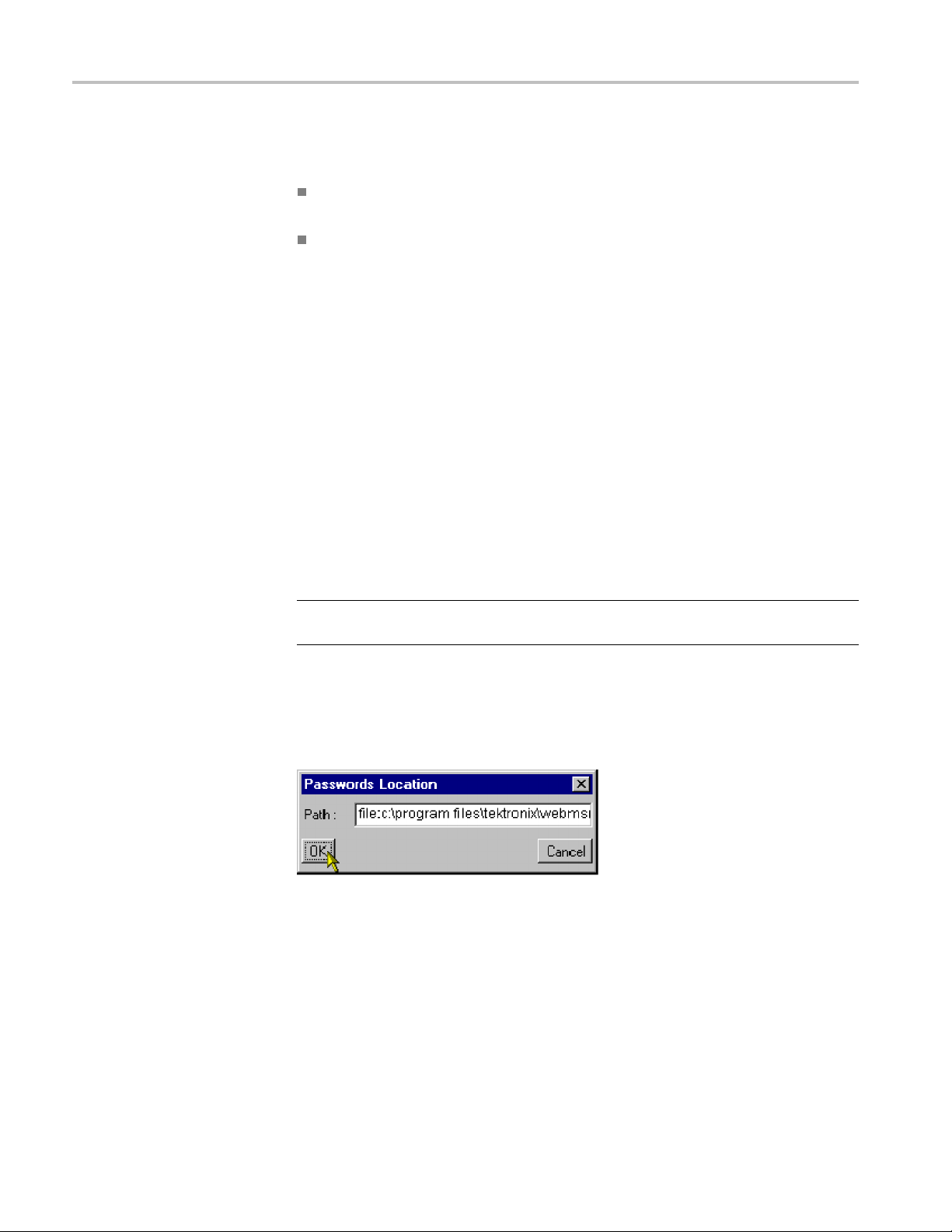
2. In the Password
NOTE. In all cases, the file name (passwords) is omitted.
3. Select OK.
4. With the location of the passwords file identified, select User > Logon.The
Login Detai
5. Select U
6. Enter a password (if required). The person designated as the Administrator is
respon
7. Select OK.
ser from t he User drop-down list.
sible for the allocation of passwords.
Location dialog box, enter the full path to the passwords file.
ls dialog box is displayed.
WebMSM Viewer
Proceed to First User for Monitoring. (Seepage1-22.)
The WebMSM Viewer application is installed by default at the same location as
the WebMSM files. If the files have not been installed at the default location, you
must use the WebMSM DTV Monitor Viewer menu to locate and specify the new
location of the WebMSM Viewer files.
WebMSM Web Monitoring System Manager User Manual 1–15
Page 30

Installation
Administrator Installation
Installation for an Administrator includes the following processes:
Installing the WebMSM Configuration Editor
Installing and Starting the
WebMSM Configuration
Editor
Starting the
Setting the Passwords
Saving the Password File
Uploading the Password File
Installing the WebMSM
NOTE. It is the WebMSM administrator who sets up passwords. Password
information must be given to WebMSM users before they can successfully access
the WebMSM interface.
The WebMSM Configuration Editor installation files are available from the
Tektronix Web site. On the site, search for "WebMSM configuration editor",
e the latest software version, and download.
locat
1. From your download location, run
2. Step through the installation process, following the on-screen instructions
as necessary.
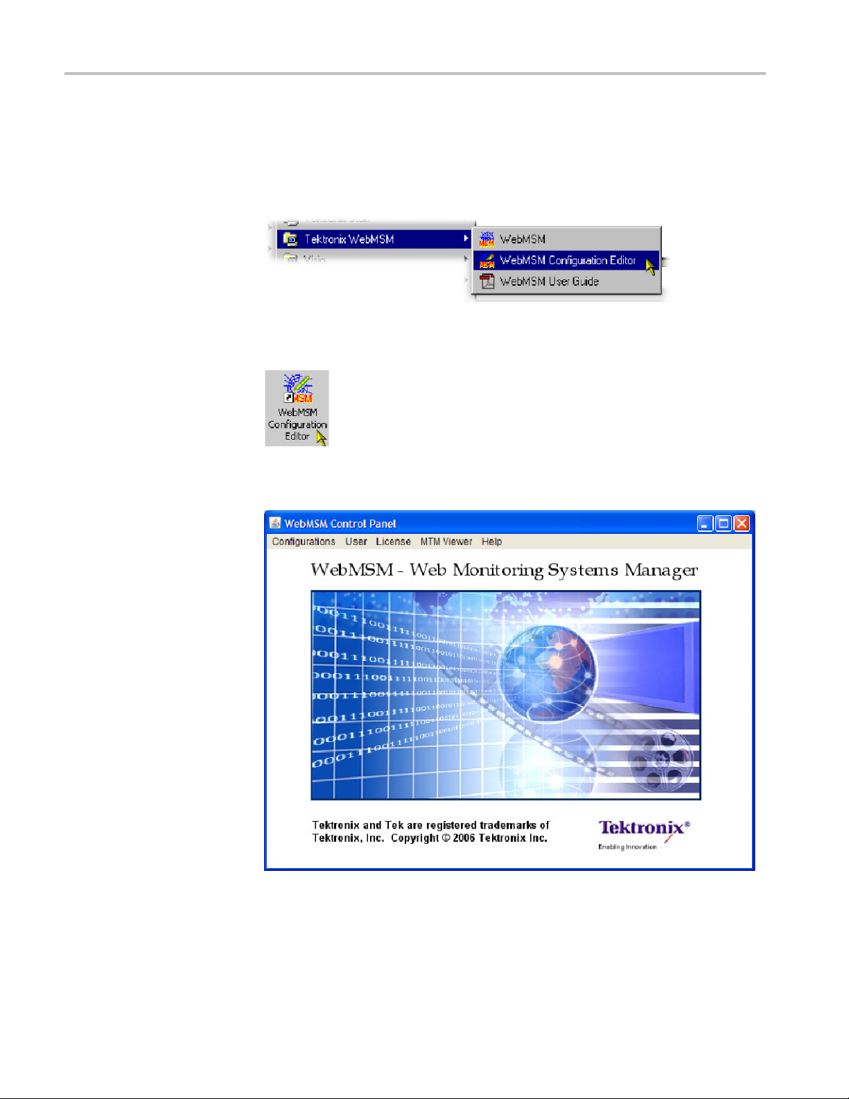
3. Start WebMSM Configuration Editor either from the desktop shortcut (created
during installation):
WebMSM Configuration Editor
setup.exe.
or the Start > Programs > Tektronix WebMSM > WebMSM Configuration
Editor option.
1–16 WebMSM Web Monitoring System Manager User Manual
Page 31

Installation
Setting Passwords
Figure 1-6: WebMSM Configuration Editor - Initial administrator screen
Only an operator designated as an administrator can create or edit a password
file for use by the WebMSM. It is assumed that a user acc essing the WebMSM
Configuration Editor is an administrator, and therefore no password is required
to open the application. However, both a user and an administrator require a
password to access the WebMSM.
Passwords must be set for a n ew installation. A common password file can be
used for multiple installations if the file is accessible by either a network or
aWeb
server. For example:
Local:
e:c:\program files\tektronix\webmsm\security\
fil
Network:
file:\\server/path/
Web Server :
http://streamview01/
Password files can also be uploaded to individual DTV monitors (or lists of DTV
monitors). This allows passwords which will be used to access WebMSM to be
administered using the WebMSM Configuration Editor.
WebMSM Web Monitoring System Manager User Manual 1–17
Page 32

Installation
1. Select User > Se
This dialog box is used to set the User and the Administrator password.
2. Enter the required password in the Administrator - Password field. Repeat
the password in the Administrator - Verify Password field.
tPasswords. The Set Passwords dialog box is displayed.
ng the Password File
Savi
Repeat for the User password.
Use Save to save the passwords to the passwords file either locally or on a
network. (See page 1-18, Saving the Password File.) Use Upload to save the
passwords file to DTV monitors. (See page 1-20, Uploading the Password Files.)
1. Select Save.
If a blank password has been set for either user, a message box is displayed.
NOTE. While a blank password is permissible, for security reasons it may not
be advisable.
1–18 WebMSM Web Monitoring System Manager User Manual
Page 33
Installation
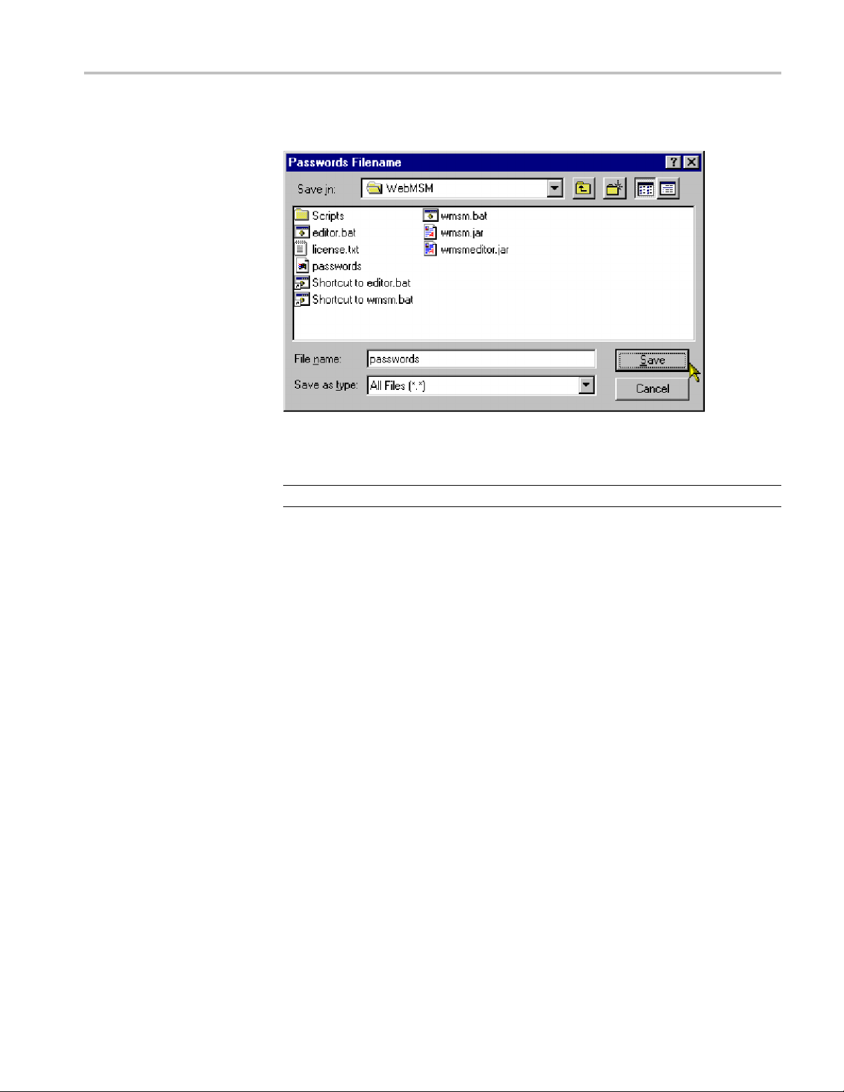
2. The Password Fi
This is a standard Windows feature. Select the required location and Save in
the sele
NOTE. Always name the file "passwords."
cted directory.
lename dialog box is displayed.
3. Unless
proceed to install the WebMSM. (See page 1-21, Installing WebMSM.)
the password file is also to be uploaded to individual DTV monitors,
WebMSM Web Monitoring System Manager User Manual 1–19
Page 34

Installation
Uploading the Password
Files
This feature al
and thus set the password for any user accessing the WebMSM through the RUI.
1. Select Upload
If a blank password has been set for either user, a message box may be
displayed.
NOTE. While a blank password is permissible, for security reasons it may not
be advisable.
2. Select OK.TheUpload Passwords dialog box is displayed.
lows the password file to be uploaded to one or more DTV monitors,
.
The RTM Devices pane displays the addresses of the DTV monitors that the
Passwords file will be uploaded to when Start is selected.
3. To create or add to the Device List, enter the DTV monitor network identity or
IP address in the Device field. Select Add to add the device to the Device List.
Devices can be deleted from the Device List using Delete. Device lists can be
saved using Save. Saved lists of devices can be loaded using Load.
Device names already in the Device List can be modified by highlighting the
device name in the list, modifying it in the Device field, and selecting Update.
1–20 WebMSM Web Monitoring System Manager User Manual
Page 35

Installation
Installing WebMSM
4. To upload the Pa
panel.
Upload progre
5. When the password file has been successfully uploaded, close the dialog
box using Cl
1. From your download location, run setu p.exe.
2. Step through the installation process, following the instructions as necessary.
It is assumed that the Passwords file has been correctly set up during
installation of the WebMSM Configuration Editor.
If the password file is not stored locally, on starting WebMSM it will be
necessary to set the password location:
3. On startup, the WebMSM will display the following message (if the password
file cannot be found):
sswords file to the listed devices, select Start in the Upload
ss will be logged in the Progress window.
ose.
If the existence and location of the password file is known, the user can
locate and use it.
4. Select User > Set Passwords Location.
5. In the Passwords Location dialog box, enter the full path to the passwords
le.
fi
WebMSM Web Monitoring System Manager User Manual 1–21
Page 36

Installation
6. Select OK.
WebMSM and the WebMSM Configuration Editor have now been installed, and
the passwords
NOTE. TheWebMSMandtheWebMSMConfiguration Editor do not need to be
installed on the same PC. Configuration creation and setup can be carried out on
any PC, provided that the files thus created are made available to the WebMSM.
First User for Monitoring
This section describes first access to the WebMSM monitoring functions.
(It is assumed that the WebMSM Configuration Editor has been used to configure
the system and set up passwords.)
1. Start WebMSM from either the desktop shortcut (created during installation):
have been set up.
Start > Programs > Tektronix WebMSM > WebMSM option.
or the
2. During the start up, the Logon Details dialog box w ill be displayed (if the
words file is available).
pass
3. Select the user and enter the password (if required).
4. Select OK.
The WebMSM Control Panel is displayed.
1–22 WebMSM Web Monitoring System Manager User Manual
Page 37

Installation
Figure 1-7: WebMSM Control Panel - first use
5. Select Configurations > Select from the Control Panel menu bar.
The Select Configuration dialog box is displayed.
6. Select an opening configuration from the Configuration Lis t .
WebMSM Web Monitoring System Manager User Manual 1–23
Page 38

Installation
If the configura
their location.
a. From the Contr
b. The Configuration Location dialog box is opened.
c. Enter the configuration files path.
d. Select OK.
7. From the S
The following diagram shows a pictorial example of the process. (See Figure 1-8.)
Configur
From the users point of view, the Streams and Device views are the point at which
monito
The Streams and Device views are not described here; they will vary depending
on the
reference for a detailed description of these views.
ations will vary in content and the number of Hot Spot levels.
ring of a probe or a device starts.
DTV monitor being monitored. Refer to the DTV monitor technical
tion files are not available locally, it may be necessary to set
ol Panel menu bar, select Configurations > Set Locations.
elect Configuration dialog box, select the required configuration.
1–24 WebMSM Web Monitoring System Manager User Manual
Page 39

Installation
Figure 1-8: Configuration setup - example
WebMSM Web Monitoring System Manager User Manual 1–25
Page 40

Installation
1–26 WebMSM Web Monitoring System Manager User Manual
Page 41

Operating Basics
Page 42

Page 43

Using WebMSM
User Interface Overview
The WebMSM Control panel provides a gateway to the WebMSM functions
(using the Configuration menu) and a means of setting up the security (password)
options.
Hot Spot View
The main po
is through the Configurations menu in the Control Panel - specifically the
Configuration > Select option which opens the Select Configuration dialog box.
The Select Configuration dialog box lists the available configuration entry points
as definedintheConfiguration List. An entry point may be either a Hot Spot
view, or a Stream or Device view on a specific DTV monitor; this will depend on
the configuration set up using the WebMSM Configuration Editor.
The Hot Spot view allows the overall state of streams and DTV monitors to be
viewed in a graphical environment. Hot spots are icon-like images placed at
strategic points on a background image of a map or system diagram and linked to
a device, a stream, or another hot spot view.
The Hot Spot window is split into a main panel and a status banner; the latter may
be hidden. The main panel can display a background map, a system diagram
milar graphic information. Also visible in the main panel are hot spots;
or si
user-defined images and labels can b e used for hot s pots images.
Hot Spot color or the Hot Spot background color is dependent on the error
The
status of the item to which it is linked.
terms of the view that a hot spot links to, the error status of each type of hot
In
spot is determined as follows:
int of entry to the monitoring features provided by WebMSM
evice - the highest error state of the DTV monitor
D
Stream - the highest error state of the stream
Hot Spot - the highest error state of any of the hot spots on the linked hot
spot view
Hot spots can also be displayed on thestatusbanner,butinthiscasethe
background of the status banner itself will indicate the highest error state of any
hot spot (device, stream or othe r hotspot view). If no errors are present, the status
banner background will be green.
WebMSM Web Monitoring System Manager User Manual 2–1
Page 44

Using WebMSM
Color Coding
If a user clicks
on a hot spot with the left mouse button, the linked WebMSM view
will be opened. For example, if the hot spot represents a stream, the Stream view
will be started for the stream. If the hot spot represents another hot spot view, the
linked Hot Spot view will be opened.
The Hot Spot view may also be configured so that clicking the right mouse button
on a hot spot highlights a set of hot spots. This may be useful for highlighting
stream and DTV monitor hotspots that relate to the same monitoring unit.
In setting up the WebMSM user interface, a choice is offered between changing
the button colors and changing the button background color. (See page 2-23, Hot
Spot Images.) The following table shows the color scheme where the background
color option is chosen:
Table 2-
Icon Color Meaning
1: Color coding - background
White
Red Error detected and still present
Operation normal - no error detected
Yellow
Gray The corresponding test has been disabled (or is
sient error, which has now corrected itself
Tran
unavailable). All buttons are gray indicates that
connection to a device has been lost
2–2 WebMSM Web Monitoring System Manager User Manual
Page 45

Using WebMSM
The following t
able gives examples of buttons that may be used where the button
color is to indicate the error state.
Table 2-2: Color coding - buttons
Icon Color Meaning
Green Operation normal - no error detected
Red Error detected and still present
Yellow
Gray The corresponding test has been disabled (or is
Transient error, which has now corrected itself
unavailable). All buttons are gray indicates that
connection to a device has been lost
Stream and Device Views
The Str
eams and Device views are not described here; they will vary depending
on the DTV monitor being monitored. Refer to the monitor user manual for a
detailed description of these views.
WebMSM Web Monitoring System Manager User Manual 2–3
Page 46
Using WebMSM
Opening the We
bMSM Control Panel
The WebMSM can be started by selecting Start > Tektronix WebMSM >
WebMSM.
or by double clicking the WebMSM shortcut on the desktop.
The WebMSM Control Panel opens.
Figure 2-1: WebMSM Control Panel - open
Closing WebMSM
2–4 WebMSM Web Monitoring System Manager User Manual
Select Configurations > Exit to close the WebMSM and all associated windows.
Page 47

Using WebMSM
Menus and Opti
Configurati
ons Menu
User Menu
ons
The Menu Bar provides access to all WebMSM control options using drop-down
menus.
Options displayed in the menus are context sensitive. They may be grayed out
depending on the level of access granted to the user (Administrator or User).
Table 2-3: Configurations Menu commands
Command Function
Select Opens the Select Configuration dialog box
Set Location Allows the location of the configuration files to be set
Close All Closes all associated WebMSM windows; the Control Panel
remains open
Exit
Closes the WebMSM Control Panel
Table 2-4: User Menu commands
Command Function
Logon
Set Passwords Location Allows the location of the password file to be set
Set Passwords (Administrator only) Allows passwords to be set
Opens the Logon Details dialog box
Password setup is described in the Installation section. (See page 1-11,
Installation.)
WebMSM Web Monitoring System Manager User Manual 2–5
Page 48

Using WebMSM
License Menu
CAUTION. Do not change the license details. If the details are changed, access
to unlimited probes will be lost and you will be unable to reopen the WebMSM
application.
Table 2-5: License Menu commands
Command Function
View Details
Update Allows license details to be viewed
Opens the License Details dialog box and allows license details
to be viewed
MTM Viewe
Help Menu
rMenu
Table 2-6
Command Function
MTM View
: MTM Viewer Menu commands
er Location
Identifies the location of the DTV monitor viewer
Table 2-7: Help Menu commands
Comman
About
d
Functi
Opens t
on
he About WebMSM dialog box; this gives program details
2–6 WebMSM Web Monitoring System Manager User Manual
Page 49

Using WebMSM
Accessing Con
figuration Lists
The list of configurations that is displayed in the Select Configuration dialog box
is derived from the Configuration List stored in the config.txt file created by the
WebMSM Config
configuration directory automatically created at installation under the WebMSM
Configuration Editor program files directory.
Configuration files do not need to be stored locally. They can be made accessible
by either sharing the default directory on a network or placing them on a Web
server. If this is done, the Configurations > Set Location option in the Control
Panel should be used to indicate the location of the configuration files.
Example:
Other
Web S e rv er : http://<network id or IP address>/
uration Editor. By default, configuration files are stored in the
directory:
file://<drive>:\<path>\webmsm\configuration\
If the Path field is left blank, the location will be set to the default configuration
directory.
WebMSM Web Monitoring System Manager User Manual 2–7
Page 50

Using WebMSM
2–8 WebMSM Web Monitoring System Manager User Manual
Page 51

Using the WebMSM Configuration Editor
Using the WebM
SM Configuration Editor
The WebMSM Co
dialog box, to the tools that are used to create, configure, and edit the system-level
interface components of WebMSM.
The WebMSM Configuration Editor i s intended for use by the System
Administrator or the person responsible for configuring the user interface. It
will not normally be used by the system operator. It is installed as a separate
application.
All configuration files must be filed in a single directory. Since all configuration
files use the file extension .cfg, it is recommended that a naming convention is
adopted to enable the different configuration types (Hot Spot, Stream, Device) to
be ident
stream_ or device_, for example, stream_sv01.cfg.
For lar
hierarchical system diagram be drawn before using the Configuration Editor.
This will aid the user in visualizing the system configuration requirements.
Configuration file names can be allocated from the diagram.
NOTE. All configuration files associated with a single configuration must be
stored in a single directory; this can be local or remote.
ified. A suitable scheme might be to preface the filenames with hotspot_,
ge systems with many levels and probes, it is also recommended that a
nfiguration Editor provides access, using a simple Windows
Configuration files are stored by default in the configuration directory
automatically created at installation u nder the WebMSM Configuration Editor
gram files directory.
pro
WebMSM Web Monitoring System Manager User Manual 2–9
Page 52

Using the WebMSM Configuration Editor
Opening the We
bMSM Configuration Editor
Start the WebMSM Configuration Editor either from the desktop shortcut (created
during installation):
or the Star
Editor option.
The WebMS
t > Programs > Tektronix WebMSM > WebMSM Configuration
MConfiguration Editor dialog box opens.
Figure 2-2: WebMSM Configuration Editor - open
Closing the WebMSM
Configuration Editor
2–10 WebMSM Web Monitoring System Manager User Manual
Select Configurations > Exit to close the WebMSM Configuration Editor and
all associated windows. Options will be offered by the various editors to save
unsaved configuration data.
Page 53

Using the WebMSM Configuration Editor
Menus and Opti
Configurations Menu
User Menu
License Menu
ons
Table 2-8: Configuration Menu commands
Command Function
Configuration List Opens the Select Configuration dialog box
Hot Spots Opens the Hot Spot Configuration Editor
Stream Opens the Stream Configuration Editor
Device
Exit
Opens the D evice Configuration Editor
Closes the WebMSM Configuration editor control panel
Table 2-9: User Menu command
Command Function
Set Pass
words
Allows passwords to be set
CAUTION. Do not change the license details. If the details are changed, access
to unlimited probes will be lost and you will be unable to reopen the WebMSM
application.
Table 2-10: License Menu commands
Command Function
View Details
Update Allows license details to be viewed
Opens the License Details dialog box and allows license details
to be viewed
WebMSM Web Monitoring System Manager User Manual 2–11
Page 54

Using the WebMSM Configuration Editor
Help Menu
Table 2-11: Hel
Command Function
About
pMenucommand
EditinganExistingConfiguration File
The procedure for opening an existing configuration file in each editor is similar.
1. Identify the type of configuration file to be opened, for example, Configuration
List, Hotspot, Stream, Device or Event Classifications, and select the
appropriate editor from the Configuration menu.
Opens the About WebMSM dialog box; this gives program details
2. In the s
3. A standard File Open dialog box will be displayed from which the required
config
4. The selected configuration file will be opened in the appropriate editor.
If an attempt is made to open a configuration file in the wrong editor, the most
likely result is that the fields normally displayed in the editor will be blank.
elected editor, from the File menu, select File > Open.
uration file can be selected.
2–12 WebMSM Web Monitoring System Manager User Manual
Page 55

Using the WebMSM Configuration Editor
Configuration
List
The Configuration List is the entry point for the WebMSM to a system
configuration. It is the Configuration List that provides the entries in the Select
Configuratio
Each entry in the Configuration List acts as a pointer to the next level of system
configuration.
n dialog box that may be displayed after logging on to WebMSM.
Figure 2-3: Select Configuration dialog box
Only configurations at a higher level that need to be available to a user at
WebMSM start up are included in the configuration list.
The Configuration List Editor allows configuration file names to be added,
removed, and modified in the configuration list. Listed files can also be opened
editedbytheConfiguration List Editor.
and
WebMSM Web Monitoring System Manager User Manual 2–13
Page 56

Using the WebMSM Configuration Editor
To open the Confi
List.
guration List Editor, select Configuratio ns > Configuration
Figure 2-4: WebMSM Configuration List Editor
The Menu Bar contains a File menu only. The following options are available
in the File menu
Table 2-12: Configuration List Editor - File menu commands
Command Function
New
Open Opens an existing configuration list file
Save Saves the c urrent configuration list file
Save As Allows the current configuration list file to be named and saved
Exit
Opens a new configuration list file
Closes the Configuration List Editor (and all associated windows)
The buttons operate as follows:
Table 2-13: Configuration List Editor buttons
Button Function
Add
Delete
Adds a default name (config.cfg) to the configuration list. It is
automatically highlighted and displayed in the update fi eld, where
it can be renamed and updated.
Deletes the currently highlighted file name.
2–14 WebMSM Web Monitoring System Manager User Manual
Page 57

Using the WebMSM Configuration Editor
Table 2-13: Configuration List Editor buttons (cont.)
Button Function
Edit
Update
Opens the currently highlighted file for editing (see below).
Updates the configuration file list w ith any changes made in the
update field.
Adding a Configuration
List File N
ame
Deleting a Configuration
List File Name
1. Select the Add button. The default file name config.cfg is added to the file list.
2. With the file name (config.cfg) highlighted in the file list (and therefore
displayed in the update field), rename the file and select the Update button.
The file name is updated in the file list. Note also that the fi le only exists as a
name in this list; it is yet to be c reated (by editing it).
NOTE. C
list before they are edited. If a file is opened in an Editor (using the Edit button)
and saved under a different filename, the new filename will not appear in the
Configuration List until it is specifically added.
1. Highlight the file name to be deleted.
2. Select the Delete button.
The
NOTE. The file referred to is not deleted, only the reference in the configuration
list is deleted.
onfiguration filesmustbegiventheirrequirednameintheconfiguration
selected file name is deleted from the file list.
Renaming a Configuration
List File Name
WebMSM Web Monitoring System Manager User Manual 2–15
1. Highlight the file name to be changed.
2. In the update field, enter the new file name.
3. Select the Update button.
The file name is updated in the file list. The renaming does not affect the
source file, only the entry in the file list.
Page 58
Using the WebMSM Configuration Editor
Editing a Configuration
List File Name
1. Highlight the fi
2. Select the Edit button.
If the selected configuration file is found (and recognized) in the configuration
file directory, the appropriate editor will be opened with the file loaded.
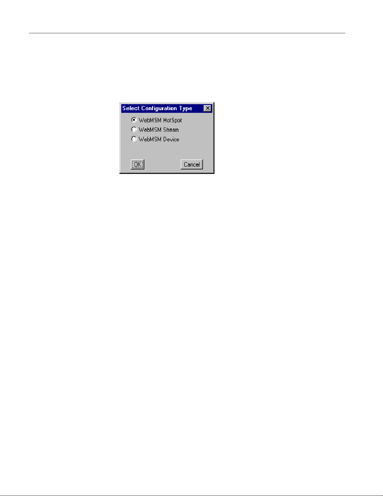
If the selected configuration file is not found in the configuration file directory,
the Select Configuration Type dialog box will be displayed. This allows the
user to specify which type of configuration file is to be created. When the
selection has been made and the OK button is pressed, the appropriate editor
will be
The operation of the other Editors is described in the following sections.
opened.
le name to be edited.
gtheConfiguration
Savin
List
1. From the Menu Bar, s elect File > Save.
2. The name and location of the Configuration List file is dependent on the
system configuration. The Configuration List file name is displayed in the
editor title bar.
2–16 WebMSM Web Monitoring System Manager User Manual
Page 59

Using the WebMSM Configuration Editor
Hot Spot Edito
r
The Hot Spot Editor allows Hot Spot configuration files to be created and edited;
backgrounds can be added and hot spots can be associated with devices, streams
or other hot s
To open the Hot Spot Editor, do one of the following:
Select Configurations > Hot Spots in the main WebMSM Configuration
Editor control panel
Highlight a Hot Spot configuration file in the Configuration List Editor and
select the Edit button
Createaconfiguration file in the Configuration List Editor, use the Add button
to create a new entry in the configuration list, rename it if required and when
the Edit
Type dialog box
AnewHo
following figure. The window is blank until some hot spots, or a background
image, are added
pot diagrams.
button is used, select WebMSM Hot Spot in the Select Configuration
t Spot window will be displayed in the Hot Spot Editor as shown in the
Figure 2-5: WebMSM Hot Spot Editor
WebMSM Web Monitoring System Manager User Manual 2–17
Page 60

Using the WebMSM Configuration Editor
Menu Bar
The Hot Spot Edi
tor displays the images that will be visible in the WebMSM Hot
Spot view. The main window has two panels: the Main Panel and the Status
Banner.
The Main Panel will commonly contain a background image of a physical area or
a system diagram on which monitoring points are signified by Hot Spot images.
The Hot Spots link to Device, Stream or other H ot Spot applications.
The Status Banner is not displayed when the Hot Spot Editor is first opened; select
Status Banner > Display . The Status Banner provides a means of monitoring a
group of devices, for example, the monitoring points from a selected stream.
In the WebMSM application, the background color of each Hot Spot or the Hot
Spot image itself in the Main Panel is dependent on the error status of the item
that it is linked to. In the Status Banner, the highest error state of any Hot Spot in
both pan
els will be indicated by the overall background color.
The Menu Bar provides access to all editor options through the drop-down menus;
some options are context sensitive and may be disabled. Also, a number of menu
ns are available from pop-up menus displayed when the right mouse button
optio
is clicked once; these pop-up menu options are also context sensitive.
Achec
kmark(
) next to a pop-up menu option indicates that the feature is
currently visible; no check mark means that it is hidden.
Table 2-14: Hot Spot Editor - File Menu commands
Command Function
New
Open Opens an existing Hot Spot configuration file
Save Saves the current Hot Spot configuration list file
Save As Allows the current configuration list file to be named and saved
Check A gainst License Checks the number of probes accessible from the currently
Exit
Opens new Hot Spot configuration file
selected Hot Spot configuration file
Closes the Hot Spot Editor
2–18 WebMSM Web Monitoring System Manager User Manual
Page 61

Using the WebMSM Configuration Editor
Table 2-15: Hot
Command Function
Title
Bring to Front On Error
Table 2-16:
Command Function
Add to Main
Add to Sta
Delete
Spot Editor - Frame Menu commands
Allows the name displayed in the title bar of the Hot Spot
application to be edited
When enabled (
brought to the front of the displayed views when any of the Hot
Spots indicates an error
), indicates that this Hot Spot view should be
Hot Spot Editor - Hot Spots Menu commands
Display
tus B anner
Adds a Hot Spot icon to the Main Panel. A sequential hot spot
name is allocated; this name can be changed in the Hot Spot
Details di
Adds a Hot
spot name is allocated; this name can be changed in the Hot
Spot Details dialog box
Displays a list dialog box from which a Hot Spot can be selected
for dele
alog box
Spot icon to the Status Banner. A sequential hot
tion
Table 2-17: Hot Spot Editor - Main Panel Menu commands
Command Function
Select Background
Clear Background Clears the current Main Panel background
Display Labels
Allows a background to be added to the Main Panel
When
Panel
enabled (
), displays the Hot Spot labels in the Main
Table 2-18: Hot Spot Editor - Status Banner Menu commands
Command Function
Display
play Labels
Dis
When enabled (
When enabled (
Banner
), displays the Status Banner
), displays the Hot Spot labels in the Status
WebMSM Web Monitoring System Manager User Manual 2–19
Page 62

Using the WebMSM Configuration Editor
Backgrounds
Backgrounds in
function other than to act as a visual reference. If required, a background can be
changed without affecting the operation of the Hot Spots. Backgrounds can be
in either GIF or JPEG graphics format. Image size is not important except with
respect to usability; however, the image cannot be resized in the editor window.
the Hot Spot views are simply images; they perform no active
Figure 2-6: WebMSM Hot Spot Editor - backgrounds
To add a background to the Main Panel, select the Select Background option
from the Main Panel menu. Use the Select Background dialog box to locate and
select a background.
2–20 WebMSM Web Monitoring System Manager User Manual
Page 63

Using the WebMSM Configuration Editor
Hot Spots
Adding a Hot Spot
Hot Spots provi
Stream or another Hot Spot application. In the Main Panel, Hot Spots can be
dragged to any position; each Hot Spot can be specified in one of the following
forms:
The Hot Spot image itself can change color with the error state, in which case
an appropriately colored image must be specified for each state.
The Hot Spot background color can change color for each error state, in which
case only a single Hot Spot image need be specified.
Different styles of Hot Spot can be used in a single Hot Spot view.
A set of default Hot Spot images are provided to be used if no other images are
specified by the user.
Various properties can be associated with a Hot Spot; these are listed in the
description of the Hot Spot properties below.
AHotSp
1. From the Hot Spots menu, select the Add to Main Display option (or the
Add to
2. In the Main Panel, drag the Hot Spot to the required location.
de links to subsequent layers of a system; they can link to Device,
ot is added to the selected display a rea.
Status Banner option).
3. In either panel, with the cursor over the Hot Spot, select the Edit option from
the right-click menu (or double-click the Hot Spot image).
4. Edit the Hot Spot properties; see the following pages.
WebMSM Web Monitoring System Manager User Manual 2–21
Page 64

Using the WebMSM Configuration Editor
Hot Spot Proper
ties.
Figure 2-7: Hot Spot Details dialog box
Table 2-19: Hot Spot Details dialog box commands
Command Function
1
Name
Images
Configuration
1
Highlight Hot Spots A comma-delimited list of Hot Spot names that will all be
Error Command A command which will be executed on the Client PC if the Hot
Error Audio Clip An audio clip file name that will be played if the Hot Spot signals
1
Name and Configuration are the only required fields
The name of the Hot Spot; this name is displayed in the Hot Spot
label. Up to 11 characters can be used.
Allows the Hot Spot images (buttons) to be set up.
The configuration file that the Hot Spot is linked to; Device,
Stream or another Hot Spot.
If the named configuration file exists, the Edit button will open the
configuration file in the appropriate editor.
If the named configuration file does not exist, the Select
Configuration Type dialog box will be displayed from which the
user can select the configuration type to be created; when OK is
selected, the appropriate editor will be opened.
highlighted when the user right-clicks any of the named Hot
Spots in the WebMSM Hot Spot view.
Spot signals a (red) error state.
a (red) error state.
Audio c lips must be provided as .au files in eight-bit, mono µ-law
format.
2–22 WebMSM Web Monitoring System Manager User Manual
Page 65

Using the WebMSM Configuration Editor
HotSpotImages
For related inf
This dialog box specifies images to be used for Hot Spots. Any GIF or JPEG
format image c
x 32 pixels.
If the Button Images check box is selected in the Hot Spot State Indicator area,
the Button I
is selected in the Hot Spot State Indicator area, the Background Color Mode
area is made active.
ormation, see also Color Coding.(Seepage2-2.)
an be used; the maximum recommended image size is 32 pixels
magesModeareaismadeactive. IftheBackgroundColorcheckbox
Figure 2-8: Hot Spot Images dialog box
Selecting Hot Spot State Indicator. This selection dictates whether the Hot Spot
ge or the Hot Spot button background indicates the error state of the linked
ima
item.
Selecting Button Images. With the Button Images check box selected in the Hot
Spot State Indicator area, enter, or browse and select an image file for each button
color. These images will be used to indicate the error state of the associated
onfiguration item.
c
If images are not specified, default buttons will be used.
WebMSM Web Monitoring System Manager User Manual 2–23
Page 66

Using the WebMSM Configuration Editor
Selecting Back
selected in the Hot Spot State Indicator area, enter or browse and select the image
file to be used. The background color of this image will be used to indicate the
error state of the associated configuration item.
ground Color Mode. With the Background Color check box
Save Hot Spot View
If no image is specified, a default gray background is used.
When editing is complete, the Hot Spot view can be saved using File > Save.
When configuration files are saved, the .cfg e xtension is added automatically, if
necessary. Images specified as the Main Panel Background or Hot Spot images
opiedtothesamedirectoryastheconfiguration file.
are c
2–24 WebMSM Web Monitoring System Manager User Manual
Page 67

Stream Editor
Using the WebMSM Configuration Editor
The stream configuration file provides a means of identifying a single stream and
subsequently opening the Stream view in WebMSM. The stream is identified by
its position
or number on an RTM device; the RTM device is identified by its IP
address or Network identity.
Adding a New Stream
Configurati
on File
1. From the WebMSM Configuration Editor control panel, select Configurations
>Stream.
The Stream Configuration Editor dialog box is displayed:
Figure 2-9: WebMSM Stream Configuration Editor
The File menu has the following options:
Table 2-20: Stream Configuration Editor - File Menu commands
Command Function
New
Open Opens an existing Stream configuration file to be opened
Save Saves the current Stream configuration file
Save As Allows the current Stream configuration file to be named and
Exit
Opens a new Stream configuration file
saved
Closes the Stream Configuration Editor
2. Enter the Host Name of the Device; the IP address or the network identity
can be used.
3. Enter the Stream number of the device.
4. Save the configuration file (File > Save), naming it as required.
When configuration files are saved, the .cfg extension is added automatically,
if necessary.
To be accessible, the configuration file must be identified in either a configuration
list or as a hot spot.
WebMSM Web Monitoring System Manager User Manual 2–25
Page 68

Using the WebMSM Configuration Editor
Editing a Stream
Configuration File
Deleting a Stream
Configuration File
Device Editor
Adding a New Device
Configuration File
1. From the WebMSM
>Stream.
2. Select File > O
3. Edit the parameters as required.
4. Save the con
TheappearanceofaStreamConfiguration File name can be removed from either
aconfiguration list or from a Hot Spot diagram. If the file is to be completely
deleted fr
The Devi
and subsequently opening the Device view in WebMSM. The device is identified
by its IP address or Network identity on the network.
1. From th
om the system, standard Windows commands must be used.
ce Configuration file provides a means of locating a single RTM device
>Device.
figuration file (File > Save).
eWebMSMConfiguration Editor control panel, select Configurations
Configuration Editor control panel, select Configurations
pen and select the required Stream Configuration file.
The De
Figure 2-10: WebMSM Device Configuration Editor
vice Configuration Editor dialog box is displayed:
2–26 WebMSM Web Monitoring System Manager User Manual
Page 69

Using the WebMSM Configuration Editor
The File menu co
mprises the following options:
Table 2-21: Device Configuration Editor - File Menu commands
Command Function
New
Open Opens an existing Device configuration file to be opened
Save Saves the current Device configuration file
Save As Allows the current Device configuration file to be named and
Exit
2. Enter th
e Host Name of the Device; the IP address or the network identity
Opens a new Device configuration file
saved
Closes the D evice Configuration Editor
can be used.
3. Save the
configuration file (File > Save), naming it as required.
When configuration files are saved, the .cfg extension is added automatically,
if nece
ssary.
To be accessible, the configuration file must be identified in either a configuration
r as a hot spot.
list o
Editing a Device
Configuration File
leting a Device
De
Configuration File
1. From the WebMSM Configuration Editor control panel, select Configurations
>Device.
2. Select File > Open and select the required Device Configuration file.
it the Host Name as required.
3. Ed
4. Save the configuration file (File > Save).
The appearance of a Device Configuration File name can be deleted from either
aconfiguration list or removed from a Hot Spot diagram. If the file is to be
completely deleted from t he system, it m ust be deleted using standard Windows
commands
WebMSM Web Monitoring System Manager User Manual 2–27
Page 70

Using the WebMSM Configuration Editor
2–28 WebMSM Web Monitoring System Manager User Manual
Page 71

Index
Page 72

Page 73

Index
C
configuration files, 1-5
configuration list,
access, 2-7
add a file name, 2-15
delete a file name, 2-15
open for ed
save, 2-16
it, 2-12
D
Device Editor, 2-26
add configuration file, 2-27
delete configuration file, 2-27
edit configuration file, 2-27
DTV mon
itor viewer, 1-9
F
first use, 1-22
H
Hot Spot Editor, 2-17
images, 2-23
menus, 2-18
save, 2-24
hot spot view,
overview, 2-1
Hot Spot,
add, 2-21
I
installation, 1-11
user, 1-12
P
passwords, 1-8
save, 1-18
upload, 1-20
1-14
user,
S
security, 1-8
Stream Editor, 2-25
add configuration file, 2-25
delete configuration file, 2-26
edit configuration file, 2-26
system confi
guration, 1-3
U
user interface,
overview, 2-1
user,
passwords, 1-14
W
WebMSM CE,
2-10
close,
WebMSM Co n figuration
Editor, See WebM S M CE
WebMSM ,
overview, 1-1
WebMSM Web Monitoring System Manager User Manual Index-1
 Loading...