

Page 1

Instructions
Rackmount (Option 1R) Kit
WCA200 and WCA200A Series
Portable Wireless Communication Analyzers
RSA200, RSA2000A and RSA3000A Series
Real-Time Spectrum Analyzers
075-1263-03
Warnin g
The servicing instructions are for use by qualified
personnel only. To avoid personal injury, do not
perform any servicing unless you are qualified to
do so. Refer to all safety summaries prior to
performing service.
www.tektronix.com
*P075126303*
075126303
Page 2

Copyright © Tektronix. All rights reserved. Licensed software products are owned by Tektronix or its subsidiaries or
suppliers, and are protected by national copyright laws and international treaty provisions.
Tektronix products are covered by U.S. and foreign patents, issued and pending. Information in this publication supercedes
that in all previously published material. Specifications and price change privileges reserved.
TEKTRONIX and TEK are registered tradema rks of Tektronix, Inc.
Contacting Tektronix
Tektronix, Inc.
14200 SW Karl Braun Drive
P.O. Box 500
Beaverton, OR 97077
USA
For product information, sales, servic e, and technical support:
H In North America, call 1-800-833-9200.
H Worldwide, visit www.tektronix.com to find contacts in your area.
Page 3

Service Safety Summary
Only qualified personnel should perform service procedures. Read this Service
Safety Summary and the General Safety Summary before performing any service
procedures.
Do Not Service Alone. Do not perform internal service or adjustments of this
product unless another person capable of rendering first aid and resuscitation is
present.
Disconnect Power. To avoid electric shock, disconnect the mains power by means
of the power cord or, if provided, the power switch.
Use Care When Servicing With Power On. Dangerous voltages or currents may
exist in this product. Disconnect power, remove battery (if applicable), and
disconnect test leads before removing protective panels, soldering, or replacing
components.
To avoid electric shock, do not touch exposed connections.
Rackmount Instructions
i
Page 4

Service Safety Summary
Rackmount Instructions
ii
Page 5

General Information
This introduction describes the WCA Wireless Communication Analyzers and
RSA Real-Time Spectrum Analyzers Rack Adapter Kit, discusses its effects on
analyzer performance, and lists its clearance requirements. Please read these
topics before attempting to rackmount your analyzer.
The remainder of this document refers to the WCA Wireless Communication
Analyzers and RSA Real-Time Spectrum Analyzers generically as analyzers.
Products
WCA230A and WCA280A All serial numbers
WCA230 and WCA280 All serial numbers
RSA2203A and RSA2208A All serial numbers
RSA230 and RSA280 All serial numbers
RSA3303A and RSA3308A All serial numbers
RSA3408A All serial numbers
Rack-Adapter Kit Description
The rack adapter kit is a collection of parts that, once installed, configure the
analyzer for mounting in a standard 19-inch equipment rack.
NOTE. A standard equipment rack has rails with universal hole spacing. If you
use a rack with other than universal hole spacing, you may have to drill
additional mounting holes in the rack.
The dimensional drawing in Figure 3 on page 5 illustrates the rack-adapted
analyzer.
Warranted Characteristics
When the analyzer is installed according to the instructions in this document, the
rackmounted analyzer meets all warranted requirements except for those listed in
Environmental R equirements on page 2. Analyzers mounted using methods
other than those described in these instructions may cause the analyzer to not
meet its warranted requirements.
Rackmount Instructions
1
Page 6

General Information
Cooling air enters on the right side as shown in Figure 1. You must provide
adequate cool air to meet the exhaust temperature requirements.
Cool air inHot air out
Environmental
Requirements
Figure 1: Analyzer cooling
Refer to Specification in the user or service manual that applies to your analyzer
model for tables of the warranted characteristics.
The following environmental characteristics supercede those listed in the user or
service manual.
Characteristic Description
Temperature, operating
Inside rack cabinet +10 _Cto+40_C
Rackmount Instructions
2
Page 7

Clearance Requirements
The rack in which the rack adapted analyzer is mounted must provide the
following clearance requirements:
H A minimum of 264.5 mm (10.4 in) of vertical space.
H A minimum width of 441.6 mm (17.4 in) between the left- and right-front
H A minimum inside depth of at least 486.0 mm (19.1 in).
CAUTION. Adhering to these clearance requirements mounts the rack adapted
analyzer with sufficient for air circulation and accommodation of the power cord
and mounting hardware. Failure to provide these clearances can result in
overheating and can cause the analyzer to operate improperly and/or fail.
General Information
rails in the rack.
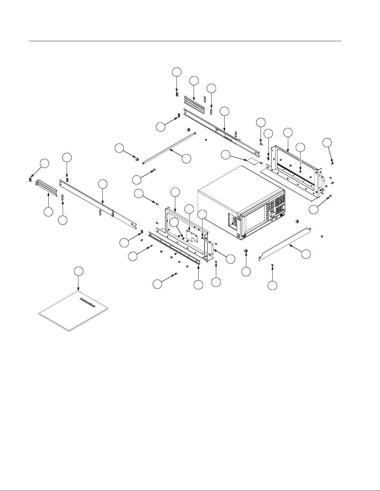
Kit Parts List
Figure 2 on
page 4
2-1 1 ea. 333-4538-01 PANEL, FRONT BLANK PANEL FOR RACK
2-2 1 ea. 407-5226-00 BRACKET HOLDING CABLE
2-3 1 ea. 407-5223-00 BRACKET SLIDE GUIDE LEFT
2-4 1 ea. 407-5224-00 BRACKET SLIDE GUIDE RIGHT
2-5 2 ea. 367-0525-00 HANDLE CARRYING
2-6 1 ea. 351-0313-01 GUIDERACKMOUNT
2-7 1 ea. 351-0241-01 SLIDE DWR EXT
2-8 2 ea. 407-5250-00 BRACKET, RAIL; EXTENDER REAR
2-9 8 ea. 211-A039-00 SCREW M4x14mm SEMS
2-10 15 ea. 212-0518-00 SCREW 10-32x0.312 inch, PNH
2-11 8 ea. 212-0509-00 SCREW 10-32x0.625 inch, PNH
2-12 4 ea. 212-0574-00 SCREW 10-32x0.438 inch FLH
2-13 12 ea. -- -- -- -- -- -- -- -- -- -- SCREW 10-32x0.354 inch, TRUSS
2-14 1 ea. 386-7496-00 PLATE, FRONT PANEL TOP, AL
Quantity Part number Description
Rackmount Instructions
2-15 8 ea. 220-0274-00 NUT, 10-32 STL, CLIP NUT
2-16 1 ea. 335-0391-00 MARKER, IDENT;SAFETY LABEL
2-17 1 ea. 075-1263-03 INSTRUCTION MANUAL, WCA2UP-1R
3
Page 8
General Information
13
8
7
7
13
15
9
13
4
10
1
11
9
11
13
15
13
7
8
7
17
11
9
13
10
9
14
3
2
12
10
6
16
5
11
Figure 2: Rackmount kit parts
4
Rackmount Instructions
Page 9

m
486.0 mm
(19.1 in)
General Information
441.6 mm
(17.4 in)
428.4 mm
(16.9 in)
536.8 mm
(21.1 in)
415.1 mm
(16.3 in)
235.0 mm
(9.3 in)
19.0 mm
(0.7 in)
22.6 mm
(0.9 in)
Figure 3: Instrument with rack adapter installed
264.5 mm
(10.4 in)
225.0 mm
(8.9 in)
450.0 mm
(17.7 in)
482.0 mm
(19.0 in)
146.0 m
(5.7 in)
482.6 mm
(19.0 in)
Rackmount Instructions
5
Page 10

General Information
Rackmount Instructions
6
Page 11
Installation Instructions
This section contains all procedures needed to rackmount the WCA or RSA
analyzer.
WARNING. To avoid personal injury, prevent the instrument from tipping or
dropping onto the installers. Two or more people should install this instrument
into the rack cabinet. Install the instrument so that the operator will be able to
access its rear panel connections without pushing on the instrument.
Equipment List
The following tools are required to attach the rack-adapter kit hardware, install
cabling hardware, and mount the rack-adapted analyzer into a standard equipment cabinet. All tools are standard tools that are readily available.
Required tools and equipment Description
Screwdriver handle Accepts Phillps-driver bits
#2 Phillips tip Phillips-driver bit for #2 size screw heads
Rackmount Instructions
7
Page 12

Installation Instructions
Strip the Analyzer for Conversion
Equipment Required: One #2 Phillips screwdriver.
NOTE. All parts removed from the analyzer in this procedure should be kept.
Some of those parts will be needed to perform this rack conversion and the
remainder will be needed if reconversion to a standard analyzer configuration is
desired at a later time.
Procedure:
1. Remove cables and rear cushions:
a. Disconnect all external cables and the power cord from the analyzer.
b. Remove the one screw securing the rear cushion over the cabinet to the
rear panel at each corner . Detach the cushions. See Figure 4.
Figure 4: Removing the rear cushions
Rackmount Instructions
8
Page 13

Installation Instructions
2. Remove the Front Cushions:
a. Remove the two screws securing the front cushion to the side panel at
each side. See Figure 5.
b. Lifting the front of the analyzer slightly, move the front cushion away.
Rackmount Instructions
Figure 5: Removing the front cushions
9
Page 14

Installation Instructions
Rackmount the Analyzer
This procedure describes how to assemble and install the slide-out tracks in the
equipment rack, and then how to install the analyzer into the rack.
Installing the Kit Hardware
M4X14 screws
(211-A039-00)
Left main bracket
Equipment Required: One #2 Phillips screwdriver.
1. Install the main brackets:
a. Install the right main bracket to the side and rear of the analyzer using
four M4 x 14 screws. See Figure 6.
b. Rotate the analyzer to face the left side and repeat step a to install the left
main bracket.
M4X14 screws
(211-A039-00)
Right main bracket
M4X14 screws
(211-A039-00)
Cable bracket
M4X14 screws
(211-A039-00)
Figure 6: Rackmount assembly
10
Rackmount Instructions
Page 15

Installation Instructions
2. Install the cable bracket:
a. If you use the USB and LAN connectors on the left side of the analyzer,
install the cable bracket to the left main bracket using three
10-32 screws. See Figure 7.
Cable bracket
Route the cables through
the cable bracket.
Figure 7: Installing the cable bracket
3. Apply the CAUTION label:
a. Remove the protective backing from the CAUTION label, and apply it
to the top center of the cabinet. See Figure 8 on page 12.
Rackmount Instructions
11
Page 16

Installation Instructions
CAUTION label
Front
Assembling the Slide-out
Tracks
Figure 8: Applying the CAUTION label on the cabinet (top view)
Equipment Required: One #2 Phillips screwdriver.
Procedure:
1. Identify the equipment rack right and left slide-out track assemblies by
finding the date code label on each assembly. The equipment rack left-side
assembly has a date code that ends with “LH”, for left hand. The equipment
rack right-side assembly has a date code ending with “RH”.
2. Measure the distance between the front and rear rail of the equipment rack.
3. Align the rear bracket to the right slide-out track as shown in
Figure 9 or Figure 10. Note that the rear bracket has multiple pairs of
mount-through holes. When aligning the bracket and track, be sure to select
a pair of holes that mount the rear bracket so that the flange-to-flange
distance matches the front rail to rear rail spacing of the rackmount rack just
measured in step 2.
4. Secure the rear bracket to the right slide-out track using two 10-32 screws
and a bar nut. Leave the screws loose so that you can adjust the overall
length of the slide-out track assembly in the rack.
12
5. Repeat steps 3 and 4 to assemble the left slide-out track assembly.
Rackmount Instructions
Page 17

Inside track
Installation Instructions
Stop latch
Rear bracket
Stop latch
Flat bar nut
Inner track
Stop latch hole
Front rack
Outer track
Rear rack
10-32 Panhead screws
Untapped hole
Flat bar nut
Flat bar nut
Untapped hole
10-32 Panhead screw
Figure 9: Assembling the slide-out tracks (for untapped rails)
Rackmount Instructions
13
Page 18

Installation Instructions
Inside track
Stop latch
Rear bracket
Stop latch
Flat bar nut
Inner track
Front rack
Stop latch hole
Outer track
Rear rack
10-32 Panhead screws
Tapped hole
Flat bar nut
Tapped hole
10-32 Panhead screw
Figure 10: Assembling the slide-out tracks (for tapped rails)
14
Rackmount Instructions
Page 19

Installation Instructions
Mounting the Slide-out
Tracks
1. Select a 1/2 inch spaced hole in the front rail.
2. Select the mounting method according to your rack type:
H To mount the slide-out tracks with their front and rear flanges outside of
the front and rear rails, use method A shown in Figure 11 when doing
step 3. This mounting method assumes tapped holes.
H To mount with front and rear flanges inside of rack rails, use mounting
method B shown in Figure 11. This mounting method assumes untapped
holes.
3. Using the method and hardware determined from step 2, secure the right
slide-out track assembly to the equipment rack front and rear rails. The
screws should be fully, but lightly, seated so that you can adjust the rack
later. See F igure 11.
4. Tighten the screws, applying 28 inch-lbs of torque, left loose in step 4 in
Assembling the Slide-out Tracks on page 12 to fix the front to rear flange
spacing of the slide-out track assembly.
5. Repeat steps 1 through 4 to mount the left slide-out track assembly.
Left slide-out track Left slide-out track
Bar nut
Left slide-out track
Left-front rail
10-32 Panhead
screw
Mounting Method A Mounting Method B
assembly
10-32 Flat head
Use flat head screws if the cabinet rails have countersunk
mounting holes; otherwise use panhead screws
Figure 11: Installation of slide-out track assemblies in the rack (top view)
screw
10-32 Panhead
screw
Rackmount Instructions
15
Page 20

Installation Instructions
Installing the Analyzer in
the Rack
Equipment Required: One #2 Phillips screwdriver.
Procedure: See Figure 12.
1. Install the analyzer:
a. Working from the front of the rack, slide out the inner track of each slide
guide until it stops at the catch.
b. Insert the left and right inner tracks into the tracks on the analyzer. Make
sure that the tracks on the analyzer slip inside the inner tracks.
c. Slide the analyzer backwards until it stops.
d. Push both stop latches, located on the outside of each track, and continue
to slide the analyzer all the way into the rack.
2. Level the rackmounted analyzer:
a. Tighten the four screws that were left loose at the rear of the rack when
you did step 3 in Mounting the Slide-out Tracks on page 15, then pull the
analyzer part way out of the rack.
b. Be sure the four screws that were left loose at the front of the rack are
loose enough to allow the slide guide assemblies to seek their normal
positions.
c. Retighten the four screws and push the analyzer all the way into the rack.
If the tracks do not slide smoothly, readjust the level using the method
just detailed.
d. When leveling is completed, tighten the four screws at the front of the
rack.
3. Secure the analyzer and make rear panel connections:
a. Secure the right and left main brackets to the front rails with four
10-32 screws. If the front rails have untapped holes, insert the four clip
nuts on the holes that you will use to secure the main brackets.
b. Secure the upper and lower blank panels to the front rails with four
10-32 screws. If the front rails have untapped holes, insert the four clip
nuts on the holes that you will use to secure the upper and lower blank
panels.
c. Install the power cord on the rear panel.
d. If necessary, connect cables on the rear panel.
16
Rackmount Instructions
Page 21

Clip nut (use if front
rails are not tapped)
Installation Instructions
Upper blank panel
Stop latch
Press the stop latch on each
side to slide the analyzer.
Figure 12: Installing the analyzer in the rack
Rackmount Instructions
10-32 screws
(211-0509-00)
Lower blank panel
10-32 screws
(211-0509-00)
17
Page 22

Installation Instructions
WARNING. After completing the installation procedure, the installers should
verify that the instrument and rack cabinet will not tip forward while the
instrument is in the extended position.
To avoid personal injury, operators should prevent the rackmounted instrument
from tipping forward onto them. Operators should verify that the rack does not
become unstable with the instrument fully extended. Do not leave the instrument
extended.
To remove the analyzer from the rack mount, slide it out until it stops at the
catches. Support the analyzer while you press in on the automatic latch on each
side. This action will free the analyzer to slide completely out of the rack.
Provide support while you slide the mainframe out of the rack.
g End of document g
18
Rackmount Instructions
 Loading...