

Page 1

Instructions
WCA2UP-03 & RSA3UP-03 IQ Input Function
WCA230A & WCA280A
Portable Wireless Communication Analyzers
RSA3303A & RSA3308A
Real-Time Spectrum Analyzers
075-1268-02
Warnin g
The servicing instructions are for use by qualified
personnel only. To avoid personal injury, do not
perform any servicing unless you are qualified to
do so. Refer to all safety summaries prior to
performing service.
www.tektronix.com
075126802
Page 2

Copyright © Tektronix. All rights reserved. Licensed software products are owned by Tektronix or its subsidiaries or
suppliers, and are protected by national copyright laws and international treaty provisions.
Tektronix products are covered by U.S. and foreign patents, issued and pending. Information in this publication supercedes
that in all previously published material. Specifications and price change privileges reserved.
TEKTRONIX and TEK are registered trademarks of Tektronix, Inc.
Contacting Tektronix
Tektronix, Inc.
14200 SW Karl Braun Drive
P.O. Box 500
Beaverton, OR 97077
USA
For product information, sales, service, and technical support:
H In North America, call 1-800-833-9200.
H Worldwide, visit www.tektronix.com to find contacts in your area.
Page 3
Kit Description
This kit provides parts and instructions to replace the A10 A/D board and add
Option 03 (IQ input function) to your WCA230A and WCA280A Portable
Wireless Communication Analyzers or RSA3303A and RSA3308A Real-Time
Spectrum Analyzers.
This document supports Tektronix modification ECR30645.
Products
WCA230A and WCA280A without Option 03
RSA3303A and RSA3308A without Option 03
Minimum Tool and Equipment List
Required tools and equipment Description
Screwdriver handle Accepts Phillps-driver bits
Kit Parts List
#1 Phillips tip Phillips-driver bit for #1 size screw heads
#2 Phillips tip Phillips-driver bit for #2 size screw heads
Fig. & index
number
WCA2UP-03, RSA3UP-03
1-1 1ea 671-B158-55 CIRCUIT BD ASSY:A10
1-2 4 ea 131-6607-00 CON,RF,JACK:BNC
1-3 4 ea 174-B980-00 CABLE ASSY,RF:50OHM,COAX
1-4 8 ea 211-0871-00 SCREW,MACHINE:M3X6MM L
1-5 16 ea 211-A151-00 SCREW,MACHINE:M2.5X6MM L
1-6 1 ea 334-1377-50 MARKER, IDENT
1-7 1ea 075-1268-02 INSTRUCTION MANUAL,
Quantity Part number Description
WCA2UP-03 & RSA3UP-03
WCA2UP-03 & RSA3UP-03 Instructions
1
Page 4

Kit Description
1
2
Figure 1: Kit parts
X8
4
6
X16
X4
5
7
3
X4
WCA2UP-03 & RSA3UP-03 Instructions
2
Page 5
Installation Instructions
These instructions are for personnel who are familiar with servicing the product.
If you need further details for disassembling or reassembling the product, refer to
the WCA230A and WCA280A Service Manual (Tektronix part number
071-1257-00) or the RSA3303A and RSA3308A Service Manual (Tektronix part
number 071-1412-XX).
CAUTION. To prevent static discharge damage, service the product only in a
static-free environment. Observe standard handling precautions for static-sensitive devices while installing this kit. Always wear a grounded wrist strap,
grounded foot strap, and static resistant apparel while installing this kit.
These installation instructions consist of four main processes:
H Replacing the A10 A/D board
H Installing the I and Q input connectors
H Enabling the IQ input function
H Calibrating the analyzer
WCA2UP-03 & RSA3UP-03 Instructions
3
Page 6

Installation Instructions
Replacing the A10 A/D Board
Perform the following procedure to replace the A10 A/D board.
Removing the Cabinet
You will need a Phillips #2 screwdriver.
1. Disconnect all external cables and the power cord from the analyzer.
2. Remove the one screw securing the rear foot over the cabinet to the rear
panel at each corner.
3. Remove the center two screws securing the cabinet to the rear panel.
4. Slide the cabinet backward. As you remove the cabinet, take care not to bind
or snag it on the analyzer’s internal cabling.
Figure 2: Cabinet removal
WCA2UP-03 & RSA3UP-03 Instructions
4
Page 7

Installation Instructions
Removing Old A10 Board
GPIB
W75 W41 W40
A70
DC power
A40
Memory
A30
Trigger
A20
DDC
A10
A/D
RF5
You will need a Phillips #2 screwdriver.
1. Locate the A10 A/D board in Figure 3 (top view of the card cage).
To f a n
W47 W46
Rear
TRIGINTRIG
OUT
W31 W30
Q--INQ+INI--INI+INREFINREF
OUT
W25
To remove the A10 board,
unplug the SMB cables from the
connectors indicated by ovals
(Refer to step 3 on page 6).
RF4
RF3
RF2
A62
Front
connection
CPU
Figure 3: Top view of the card cage
WCA280A or RSA3308A only
HDD
FDD
Fan
Front
WCA2UP-03 & RSA3UP-03 Instructions
5
Page 8

Installation Instructions
2. Remove the board support bracket: See Figure 4 below.
Remove the two screws securing the board support bracket to the rear
support bracket and the RF5 module. Lift the board support bracket away.
Board support bracket
A10 A/D board
Rear support bracket
Figure 4: Removing the A10 A/D board
3. Disconnect cables to access the A10 A/D board: See Figure 3 on page 5.
a. Unplug the SMB cables W40 (RF OUT) and W41 (RF IN) from the
RF5 module.
b. Unplug the SMB cables W30 and W31.
WCA2UP-03 & RSA3UP-03 Instructions
6
Page 9
Installation Instructions
4. Remove the A10 A/D board: See Figure 4 on page 6.
a. Remove the two screws securing the front shield bracket to the main
chassis.
b. Remove the two screws securing the back shield bracket to the main
chassis.
c. Lift up the A10 board with the shield brackets from the main frame.
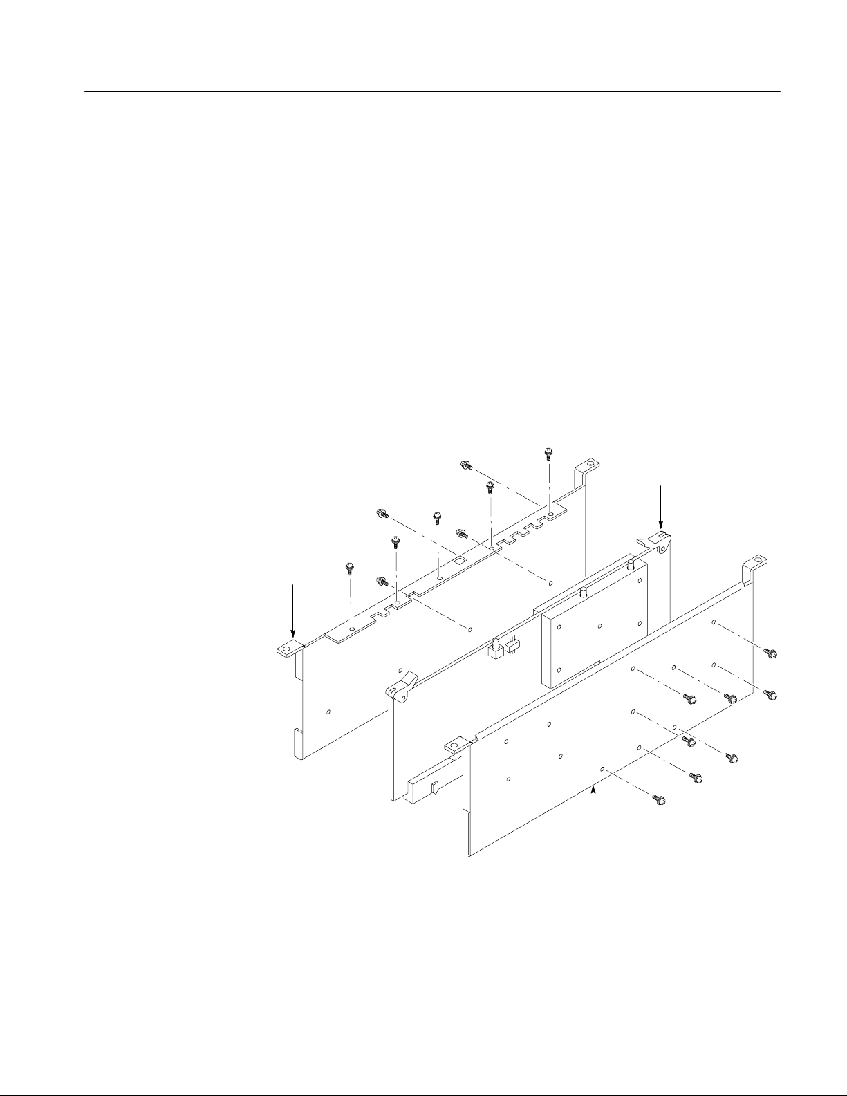
5. Remove the shield brackets: (See Figure 5 below.)
a. Remove the 8 screws securing the front shield bracket to the A10 board
to detach the bracket.
b. Remove the 9 screws securing the back shield bracket to the A10 board
to detach the bracket.
Old A10 A/D board
Back shield bracket
Front shield bracket
Figure 5: Detaching the shield brackets
WCA2UP-03 & RSA3UP-03 Instructions
7
Page 10

Installation Instructions
Installing New A10 Board
You will need a Phillips #2 screwdriver.
1. Attach the shield brackets: See Figure 6 below.
a. Secure the back shield bracket to the new A10 board with 13 screws
(Tektronix part number 211-0871-00; 9 were removed and 4 were
included in this kit).
b. Secure the front shield bracket to the A10 board with 12 screws
(Tektronix part number 211-0871-00; 8 were removed and 4 were
included in this kit).
New A10 A/D board
Figure 6: Attaching the shield brackets
2. Reverse step 4 on page 7 to install the new A10 board with the shield
brackets to its slot.
3. Reverse step 3 on page 6 to reconnect the cables.
WCA2UP-03 & RSA3UP-03 Instructions
8
Page 11

Installing the I and Q Input Connectors
Perform the following procedure to attach four BNC--SMB connectors on the
rear panel for the I and Q input.
Installation Instructions
Attaching BNC-SMB
Connectors
You will need a Phillips #1 screwdriver.
1. Remove the blank panel: See Figure 7 below.
Using a Phillips #1 screwdriver, remove the two screws securing the
blank panel to the rear panel.
Blank panel
Figure 7: Installing the IQ input connectors
2. Attach the BNC-SMB connectors: SeeFigure7.
Using a Phillips #1 screwdriver, attach the four BNC-SMB connectors
(Tektronix part number 131-6607-00) with four screws (Tektronix part
number 211-A151-00) each.
WCA2UP-03 & RSA3UP-03 Instructions
9
Page 12

Installation Instructions
Connecting SMB Cables
You will need a Phillips #2 screwdriver.
1. Remove the rear panel: See Figure 8 below.
Using a Phillips #2 screwdriver, remove the two screws securing the
rear panel to the main chassis.
Rear panel
Rear support bracket
A10 A/D board
Figure 8: Connecting SMB cables
10
WCA2UP-03 & RSA3UP-03 Instructions
Page 13

Installation Instructions
2. Move the rear panel backward gently until you can plug the SMB cables to
the IQ input connectors.
3. Connect the SMB cables (Tektronix part number 174-B980-00) W42, W43,
W44, and W45, as shown in Figure 9, from the connectors attached in the
previous step to those on the A10 A/D board.
NOTE. Pass the cables under the rear support bracket (see Figure 8 on page 10).
Rear
GPIB
A70
DC power
A40
Memory
A30
Trigger
A20
DDC
A10
A/D
RF5
Figure 9: Connecting the IQ input (top view)
TRIGINTRIG
W45 W44
Q--INQ+INI--INI+INREFINREF
OUT
OUT
W43 W42
WCA2UP-03 & RSA3UP-03 Instructions
11
Page 14

Installation Instructions
Reassembling Modules
Attaching the ID Label
1. Reinstall the rear panel by reversing step 1 on page 10.
2. Reinstall the board support bracket by reversing step 2 on page 6.
3. Reinstall the cabinet by reversing steps 1 through 4 on page 4.
After you finish the A10 A/D board and the IQ input connector installation,
attach the ID label (supplied with this upgrade kit) onto the rear panel of the
analyzer. Figure 10 shows the location for the label.
ID label
Figure 10: ID label location (rear panel)
12
WCA2UP-03 & RSA3UP-03 Instructions
Page 15

Enabling the IQ Input Function
Edit the Option.cal file on the analyzer to enable the IQ input function using the
following procedure.
1. Turn on the analyzer.
2. Connect a USB mouse and a USB keyboard to the USB ports on the
analyzer side panel. Y ou can connect them to either or both ports.
You can also connect the mouse to the USB port on the keyboard.
Installation Instructions
USB ports
Figure 11: USB ports (side panel)
Front
WCA2UP-03 & RSA3UP-03 Instructions
13
Page 16

Installation Instructions
3. Display the Windows desktop on the analyzer screen:
a. With the mouse, move the pointer to the bottom of screen.
The task bar appears.
b. Right-click on the task bar icon that indicates the analyzer model name
(WCA230A, WCA280A, RSA3303A or RSA3308A). A menu opens.
c. Select Close from the menu.
The analyzer system program stops, and the Windows desktop displays.
4. Edit the Option.cal file:
a. Open the file called D:\__RtsaCalData__\Option.cal using Windows
Notepad.
b. Add this line just below the top line:
Option:IQInput=On
c. Add “03” to the “Option=” line as in the following examples:
Examples:
Change: “Option=” to: “Option=03”
Change: “Option=02,1R” to: “Option=02,1R,03”
d. Save the Option.cal file.
5. Close all the windows on the desktop.
6. Turn off the analyzer.
14
WCA2UP-03 & RSA3UP-03 Instructions
Page 17

Installation Instructions
Verifying Operation
Option 03 added
1. Turn on the analyzer.
2. Press the SYSTEM key on the front panel.
3. Press the Versions and Installed Options... side key.
4. Check that Option 03 is added in the installed options list on screen (see
Figure 12 below).
Figure 12: Checking the installed option
WCA2UP-03 & RSA3UP-03 Instructions
15
Page 18

Installation Instructions
Calibrating the Analyzer
Perform the auto calibration, referring to Auto Calibration located in the
Adjustment Procedures section of the WCA230A and WCA280A Service Manual
(Tektronix part number 071-1257-XX) or RSA3303A and RSA3308A Service
Manual (Tektronix part number 071-1412-XX).
NOTE. Perform the auto calibration to meet warranted limits and optimize the
performance of the analyzer.
g End of document g
16
WCA2UP-03 & RSA3UP-03 Instructions
 Loading...