

Page 1

Instructions
WCA2UP-02 & RSA3UP-02
256 MB Data Memory with Frequency Mask Trigger
WCA230A & WCA280A
Portable Wireless Communication Analyzers
RSA3303A & RSA3308A
Real-Time Spectrum Analyzers
075-1267-01
Warning
The servicing instructions are for use by qualified
personnel only. To avoid personal injury, do not
perform any servicing unless you are qualified to
do so. Refer to all safety summaries prior to
performing service.
www.tektronix.com
075126701
Page 2

Copyright © Tektronix, Inc. All rights reserved.
Tektronix products are covered by U.S. and foreign patents, issued and pending. Information in this publication supercedes
that in all previously published material. Specifications and price change privileges reserved.
Tektronix, Inc., P.O. Box 500, Beaverton, OR 97077
TEKTRONIX and TEK are registered trademarks of Tektronix, Inc.
Page 3

Kit Description
This kit provides parts and instructions to install the A30 trigger board and add
Option 02 (256 MB data memory with frequency mask trigger) to your
WCA230A and WCA280A Portable Wireless Communication Analyzers or
RSA3303A and RSA3308A Real-Time Spectrum Analyzers.
Products
WCA230A and WCA280A without Option 02
RSA3303A and RSA3308A without Option 02
Minimum Tool and Equipment List
Required tools and equipment Description
ScrewdriverĂhandle Accepts PhillpsĆdriver bits
#2 Phillips tip PhillipsĆdriver bit for #2 size screw heads
Kit Parts List
Fig. & index
number
606Ć0139Ć00
1Ć1 1ea 671ĆB162Ć50 CIRCUIT BD ASSY:A30
1Ć2 1 ea 334Ć1377Ć50 MARKER,IDENT
1Ć3 1ea 075Ć1267Ć00 INSTRUCTION MANUAL
Quantity Part number Description
WCA2UPĆ02 & RSA3UPĆ02
WCA2UP-02 & RSA3UP-02 Instructions
1
Page 4

Kit Description
1
3
2
Figure 1: Kit parts
WCA2UP-02 & RSA3UP-02 Instructions
2
Page 5

Installation Instructions
These instructions are for personnel who are familiar with servicing the product.
If you need further details for disassembling or reassembling the product, refer to
the WCA230A and WCA280A Service Manual (Tektronix part number
071-1257-XX) or the RSA3303A and RSA3308A Service Manual (Tektronix part
number 071-1412-XX).
CAUTION. To prevent static discharge damage, service the product only in a
static-free environment. Observe standard handling precautions for static-sensitive devices while installing this kit. Always wear a grounded wrist strap,
grounded foot strap, and static resistant apparel while installing this kit.
These installation instructions consist of three main processes:
H Installing the A30 trigger board
H Enabling 256 MB data memory and frequency mask trigger
H Verifying operation
WCA2UP-02 & RSA3UP-02 Instructions
3
Page 6
Installation Instructions
Installing the A30 Trigger Board
Complete the following procedures to install the A30 trigger board.
Removing the Cabinet
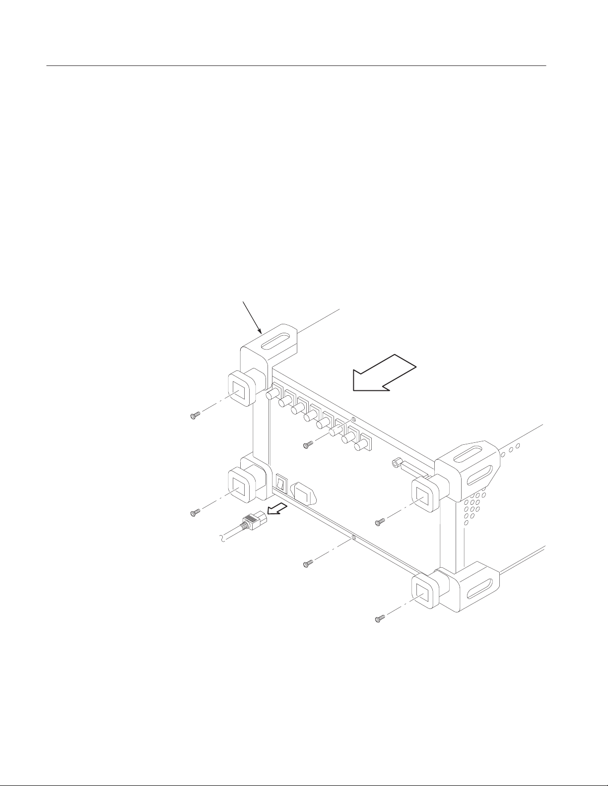
1. Disconnect all external cables and the power cord from the analyzer.
2. Remove the one screw securing the rear foot over the cabinet to the
rear panel at each corner.
3. Remove the center two screws securing the cabinet to the rear panel.
4. Slide the cabinet backward. As you remove the cabinet, take care not to bind
or snag it on the analyzer’s internal cabling.
Rear foot
Figure 2: Cabinet removal
WCA2UP-02 & RSA3UP-02 Instructions
4
Page 7

Installation Instructions
Installing the A30 Board
GPIB
A70
DC power
A40
Memory
A30
Trigger
A20
DDC
A10
A/D
RF5
RF4
1. Locate the A30 trigger board slot in Figure 3 (top view of the card cage)
below.
Rear
TRIGINTRIG
OUTQ-INQ+INI-INI+IN
To fan
W47 W46
W45 W44
WCA280A or RSA3308A only
Option 03 only
REFINREF
OUT
W43 W42 W41 W40
To access the A30 card slot,
unplug the SMB cables from the
connectors indicated by ovals
(Refer to step 3 on pageĂ7).
RF3
RF2
A62
Front
connection
CPU
Figure 3: Top view of the card cage
HDD
FDD
Fan
Front
WCA2UP-02 & RSA3UP-02 Instructions
5
Page 8
Installation Instructions
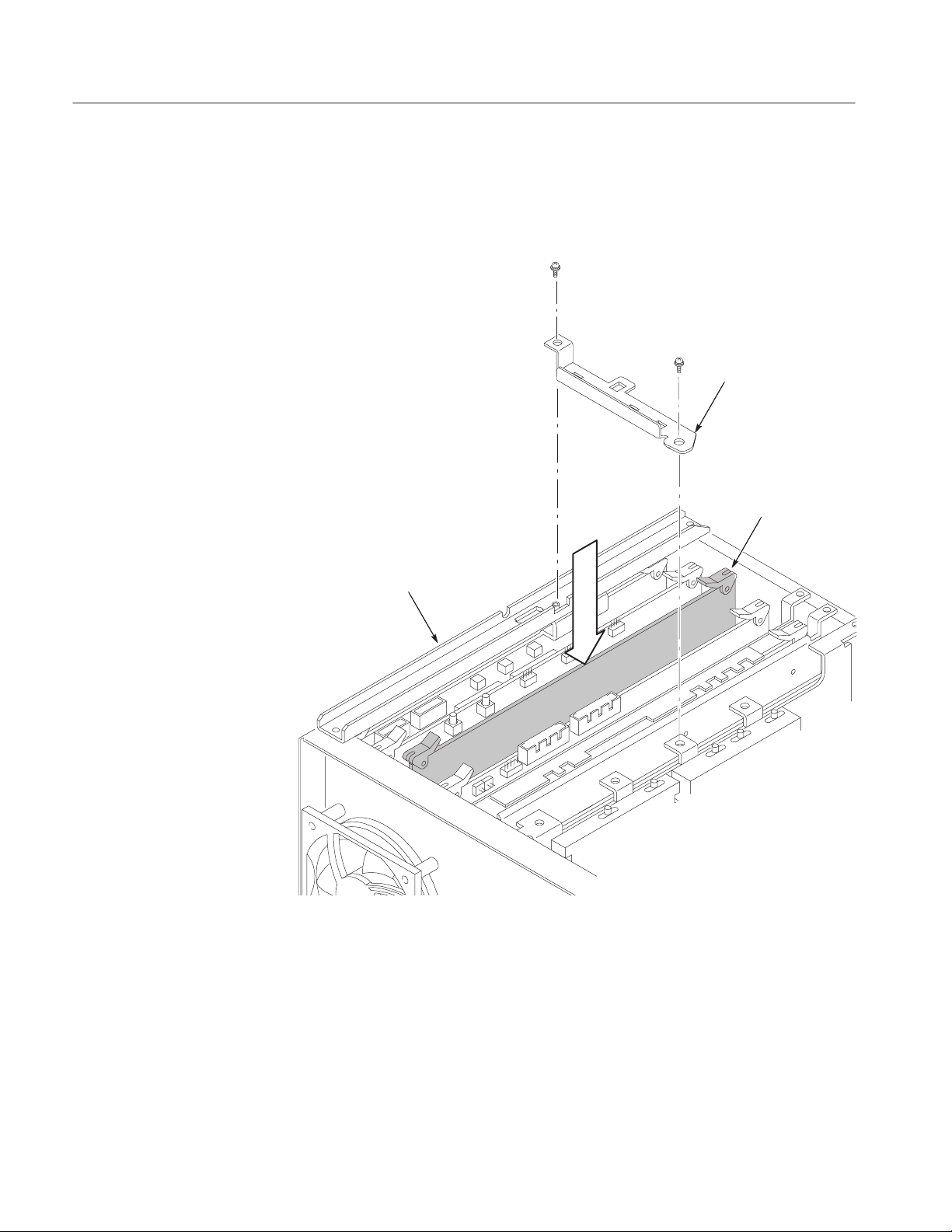
2. Remove the board support bracket: (See Figure 4 below.)
Remove the two screws securing the board support bracket to the rear
support bracket and the RF5 module. Lift the board support bracket away.
Board support bracket
A30 Trigger board
Rear support bracket
Figure 4: Installing the A30 trigger board
WCA2UP-02 & RSA3UP-02 Instructions
6
Page 9

Installation Instructions
3. Disconnect cables to access the A30 trigger board slot:
(See Figure 3 on page 5.)
a. Unplug the SMB cables W40 (RF OUT) and W41 (RF IN) from the
RF5 module.
b. Option 03 only. Unplug the SMB cables W42 (I+), W43 (I–), W44 (Q+),
and W45 (Q–) from the A10 A/D board.
4. Insert the A30 trigger board in the slot properly.
Reassembling Modules
Attaching the ID Label
1. Reconnect the cables by reversing step 3 above on this page.
2. Reinstall the board support bracket by reversing step 2 on page 6.
3. Reinstall the cabinet by reversing steps 1 through 4 on page 4.
After you finish the board installation, attach the ID label (supplied with this
upgrade kit) onto the rear panel of the analyzer. Figure 5 shows the location for
the label.
Figure 5: ID label location (rear panel)
WCA2UP-02 & RSA3UP-02 Instructions
ID label
7
Page 10
Installation Instructions
Enabling 256 MB Data Memory and Frequency Mask Trigger
Edit the Option.cal file on the analyzer to enable 256 MB data memory and
frequency mask trigger using the following procedure.
1. Turn on the analyzer.
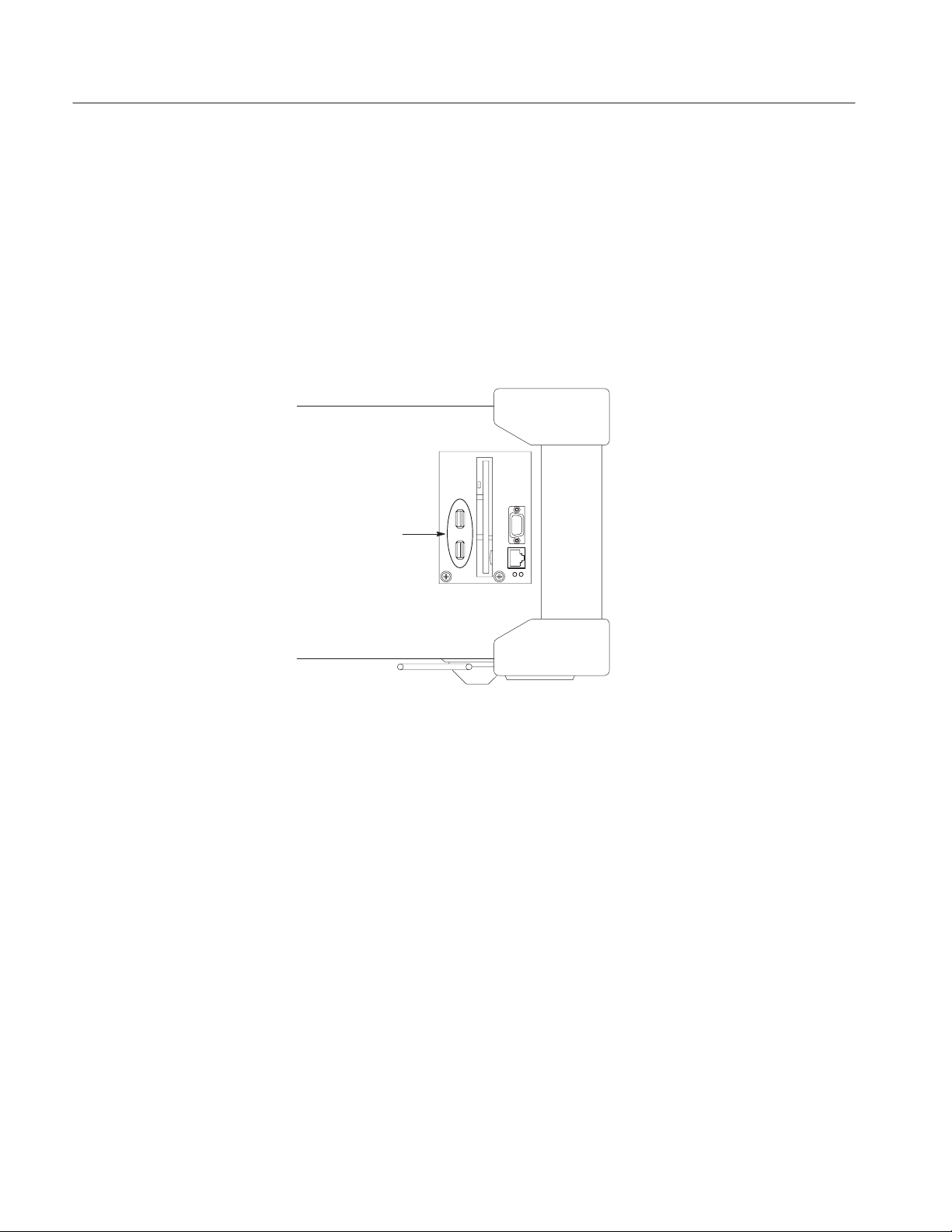
2. Connect a USB mouse and a USB keyboard to the USB ports on the
analyzer side panel. You can connect them to either or both ports.
You can also connect the mouse to the USB port on the keyboard.
USB ports
Figure 6: USB ports (side panel)
Front
WCA2UP-02 & RSA3UP-02 Instructions
8
Page 11

Installation Instructions
3. Display the Windows 98 desktop on the analyzer screen:
a. With the mouse, move the pointer to the bottom of screen.
The task bar appears.
b. Place the pointer on the icon indicating the analyzer model name
(WCA230A, WCA280A, RSA3303A, or RSA3308A) located on the
task bar, and click on it with the right button of the mouse.
A menu opens.
c. Select Close from the menu.
The analyzer system program stops, and the Windows 98 desktop displays.
4. Edit the Option.cal file:
a. Open the file D:\_RtsaCalData_\Option.cal using Windows Notepad.
b. Add “02” to the line “Option=” as the following examples:
Examples:
“Option=” to “Option=02”
“Option=03,1R” to “Option=03,1R,02”
c. Save the Option.cal file.
5. Close all the windows on the desktop.
6. Turn off the analyzer.
WCA2UP-02 & RSA3UP-02 Instructions
9
Page 12

Installation Instructions
Verifying Operation
Power on the analyzer to verify operation. The verification involves these tasks:
H Checking installed option
H Checking memory
H Checking trigger
Refer to the WCA230A and WCA280A User Manual or the RSA3303A and
RSA3308A User Manual for details on operating the analyzer.
Checking Installed Option
Option 02 added
1. Turn on the analyzer.
2. Press the SYSTEM key on the front panel.
3. Press the Versions and Installed Options... side key.
4. Check that Option 02 is added in the installed options list on screen (see
Figure 7 below).
10
Figure 7: Checking the installed option
WCA2UP-02 & RSA3UP-02 Instructions
Page 13
Installation Instructions
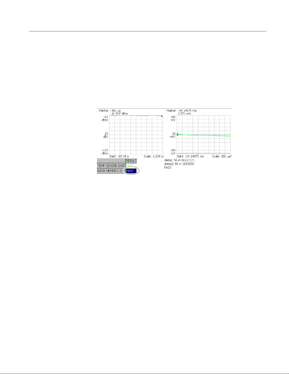
Checking Memory
1. Press the CAL key on the front panel.
2. Press the side key Service...Õ Password.
3. Enter 270833 and then press the ENTER key using the numeric keypad.
4. Press the side key DIAG Õ Data Memory.
5. Check that the result shown in the lower left view is Pass (see Figure 8).
Figure 8: Diagnostic screen
WCA2UP-02 & RSA3UP-02 Instructions
11
Page 14

Installation Instructions
Checking Trigger
Create a trigger mask and check that the trigger functions properly.
Equipment needed:
You will need the following equipment to perform this procedure:
H One signal generator
Minimum requirements: Frequency of 1.5 GHz and amplitude of –10 dBm.
H One 50 W N-N cable
1. Prepare for the test:
a. Set the signal generator controls:
Frequency 1.5 GHz. . . . . . . . . . . . . . . . .
Amplitude –10 dBm. . . . . . . . . . . . . . . .
RF output Off. . . . . . . . . . . . . . . . .
NOTE. Turn the RF output off initially.
b. Hook up the generator: Connect the generator output through a 50 W
N-N coaxial cable to the analyzer INPUT. See Figure 9.
Signal generator
Output
Figure 9: Initial test hookup
WCA230A/WCA280A or RSA3303A/RSA3308A
50 W NĆN coaxial cable
12
WCA2UP-02 & RSA3UP-02 Instructions
Page 15

Installation Instructions
c. Set the analyzer controls:
H Press the SYSTEM key on the front panel.
H Press the Reset All to Factory Defaults side key.
H Press the S/A key on the front panel
H Press the Real Time S/A side key.
H Press the RUN/STOP key to stop data acquisition.
2. Create a trigger mask:
Create a trigger mask shown in Figure 10 using the following sub-steps:
0
-30 dBm
Figure 10: Trigger mask for the functional check
a. Press the TRIG key on the front panel.
b. Press the side key Mode...→ Triggered.
c. Press the side key Source...→ Freq Mask.
d. Press the Define Mask... side key.
The mask appears, covering the whole area in blue.
e. Press the Select Marker side key to select Marker 1.
f. Press the Marker X Vertical side key and set the vertical position of the
marker to –30 dBm using the general purpose knob.
The marker appears at –30 dBm.
g. Press the side key Go to page 2 (bottom) → Draw Horizontal.
The area below –30 dBm is filled in blue as shown in Figure 10 above.
The trigger mask you created is written into the internal trigger register.
WCA2UP-02 & RSA3UP-02 Instructions
13
Page 16

Installation Instructions
3. Check the trigger:
a. Press the RUN/STOP key to start data acquisition.
b. Turn the signal generator output on:
RF output On. . . . . . . . . . . . . . . . .
c. Check that the trigger occurs. The analyzer stops data acquisition,
showing the signal peak on the spectrum view as shown in Figure 11.
0
-10 dBm
1.5 GHz
Figure 11: Spectrum display after the trigger event
g End of document g
14
WCA2UP-02 & RSA3UP-02 Instructions
 Loading...