

Page 1

User Manual
WaveWriter
(AWE) Arbitrary Waveform Editor
070-8401-08
This document supports software version 4.01E
and above.
First Printing: Jun. 2000
Page 2

Copyright E Sony/Tektronix Corporation
Copyright © T ektronix, Inc. All rights reserved. Licensed software products are owned by Tektronix or its suppliers and
are protected by United States copyright laws and international treaty provisions.
Use, duplication, or disclosure by the Government is subject to restrictions as set forth in subparagraph (c)(1)(ii) of the
Rights in T echnical Data and Computer Software clause at DFARS 252.227-7013, or subparagraphs (c)(1) and (2) of the
Commercial Computer Software – Restricted Rights clause at F AR 52.227-19, as applicable.
T ektronix products are covered by U.S. and foreign patents, issued and pending. Information in this publication supercedes
that in all previously published material. Specifications and price change privileges reserved.
Printed in the Japan
Sony/T ektronix Corporation, P.O.Box 5209, Tokyo Int’l, Tokyo 100–31 Japan
T ektronix, Inc., P.O. Box 1000, Wilsonville, OR 97070–1000
TEKTRONIX and TEK are registered trademarks of T ektronix, Inc.
MS-DOS and Microsoft are registered trademarks of Microsoft Corporation.
Windows and Windows 95 are trademarks of Microsoft Corporation.
PC-AT is a trademark of International Business Machines, Inc.
Page 3

SOFTWARE WARRANTY SUMMARY
Tektronix warrants that its software products will conform to the specifications in the documentation provided with the product,
when used properly in the specified operating environment, for a period of three (3) months. The warranty period begins on
the date of shipment, except that if the program is installed by Tektronix, the warranty period begins on the date of installation
or one month after the date of shipment, whichever is earlier. If the software product does not conform as warranted, Tektronix
will provide the remedial services as described in the documentation provided with the product.
For products offered without documentation, Tektronix warrants that the media on which the software product is furnished and
the encoding of the programs on the media will be free from defects in materials and workmanship for a period of three (3)
months from the date of shipment. If any such medium or encoding proves defective during the warranty period, Tektronix will
provide a replacement in exchange for the defective medium. Except as to the media on which the software product is
furnished, the software product is provided as is" without warranty of any kind, either express or implied.
Tektronix does not warrant that the functions contained in any software product will meet Customer's requirements or that the
operation of the programs will be uninterrupted or errorĆfree.
In order or obtain service under this warranty, Customer must notify Tektronix of the defect before the expiration of the warranty
period and, for warranted products, make suitable arrangements for such service in accordance with the instructions received
from Tektronix. If Tektronix is unable, within a reasonable time after receipt of such notice, to provide remedial service for
warranted products or, for as is" products, to provide a replacement that is free from defects in materials and workmanship,
Customer may terminate the license for the software product and return the software product and any associated materials for
credit or refund.
The above warranties shall not apply to any software product that has been modified or altered by Customer. Tektronix shall
not be obligated to furnish service under this warranty with respect to any software product a) that is used in an operating
environment other than that specified or in a manner inconsistent with the User Manual and documentation; or b) when the
software product has been integrated with other software if the result of such integration increases the time or difficulty of
analyzing or servicing the software product or the problems ascribed in the software product.
THE ABOVE WARRANTIES ARE GIVEN BY TEKTRONIX WITH RESPECT TO THE LISTED PRODUCTS IN LIEU OF ANY
OTHER WARRANTIES, EXPRESS OR IMPLIED. TEKTRONIX AND ITS VENDORS DISCLAIM ANY IMPLIED
WARRANTIES OF MERCHANTABILITY OR FITNESS FOR A PARTICULAR PURPOSE. TEKTRONIX' RESPONSIBILITY
TO PROVIDE REMEDIAL SERVICE WHEN SPECIFIED, REPLACE DEFECTIVE MEDIA, OR REFUND CUSTOMER'S
PAYMENT, AS APPLICABLE, IS THE SOLE AND EXCLUSIVE REMEDY PROVIDED TO CUSTOMER FOR BREACH OF
EITHER WARRANTY. TEKTRONIX AND ITS VENDORS WILL NOT BE LIABLE FOR ANY INDIRECT, SPECIAL,
INCIDENTAL, OR CONSEQUENTIAL DAMAGES IRRESPECTIVE OF WHETHER TEKTRONIX OR THE VENDOR HAS
ADVANCE NOTICE OF THE POSSIBILITY OF SUCH DAMAGES.
NOTE: This page is only for customers in countries other than Japan. The next page is for Japanese customers.
Page 4

Page 5

Getting Started
Operating Basics
Table of Contents
Table of Contents i............................................
List of Figures v...............................................
Preface ix.....................................................
About this Manual ix.......................................
Overview 1Ć1...................................................
What This Program Does 1Ć1.................................
What You Get With This Program 1Ć2..........................
What You Need to Run This Software 1Ć2......................
Reference
Installation 2Ć1..................................................
Software Installation 2Ć1.....................................
Configuring GPIB 2Ć2........................................
Using WaveWriter 2Ć3...........................................
Using Windows 2Ć3..........................................
WaveWriter Concepts 2Ć3....................................
The WaveWriter Window 2Ć5..................................
Setting Characteristics 2Ć7...................................
Tutorial 2Ć9.....................................................
Lesson 1 System Fundamentals 2Ć10..........................
Lesson 2 Creating and Saving a TV Signal Waveform 2Ć21.......
Lesson 3 Working with an
AWG 2020 Arbitrary Waveform Generator 2Ć37..............
Lesson 4
Working with a TDS 500 Series Digitizing Oscilloscope 2Ć42.
Menu Map 3Ć1..................................................
WaveWriter (AWE) User Manual
File Operations 3Ć5..............................................
New 3Ć5....................................................
i
Page 6

Table of Contents
Open 3Ć8...................................................
Save 3Ć12....................................................
Import 3Ć14..................................................
Export 3Ć19..................................................
Hardcopy 3Ć21...............................................
Exit 3Ć22.....................................................
About 3Ć22...................................................
Editing Waveforms 3Ć23..........................................
Undo 3Ć23....................................................
Disable Undo 3Ć24............................................
Cut Between Markers 3Ć24....................................
Copy Between Markers 3Ć24...................................
Delete Between Markers 3Ć24..................................
Insert at Start Marker 3Ć24.....................................
Replace Between Markers 3Ć25................................
Append to End of Waveform 3Ć25..............................
Flip Horizontal Between Markers 3Ć25..........................
Flip Vertical Between Markers 3Ć25............................
Horizontal Resolution 3Ć26....................................
Vertical Resolution 3Ć29.......................................
Displaying Waveforms 3Ć31.......................................
Redraw Dot 3Ć31..............................................
Redraw Vector 3Ć31...........................................
Zoom In 3Ć31.................................................
Zoom Out 3Ć32...............................................
Set Axis Ranges 3Ć32.........................................
Autoscale Current Waveform 3Ć34.............................
Show Crosshairs 3Ć38........................................
Show Multiple Waveforms 3Ć38................................
Set Colors and Line Styles 3Ć38................................
Drawing Waveforms 3Ć41........................................
Nodraw 3Ć42.................................................
Freehand 3Ć42................................................
Horizontal 3Ć43...............................................
Vertical 3Ć44..................................................
Autoline 3Ć45.................................................
Envelope Max Don't Care 3Ć46.................................
Envelope Min Don't Care 3Ć47.................................
Envelope Max 3Ć48...........................................
Envelope Min 3Ć48............................................
ii
Creating Waveforms 3Ć49.........................................
Equation 3Ć53................................................
Sine 3Ć58....................................................
Contents
Page 7

Table of Contents
Triangle 3Ć60.................................................
Pulse 3Ć63...................................................
Square 3Ć66..................................................
Envelope Tolerance 3Ć70......................................
Envelope Couple 3Ć72........................................
Envelope Decouple 3Ć74......................................
Processing Waveforms 3Ć77......................................
Add Scalar, Multiply by Scalar 3Ć77............................
Add, Subtract, Multiply, Divide Waveforms 3Ć78.................
Transferring Waveforms 3Ć83......................................
Configure Instruments 3Ć83...................................
Acquire 3Ć87.................................................
Send 3Ć88....................................................
Modifying and Listing Waveforms 3Ć89.............................
Change Clock Rate 3Ć89......................................
Change Amplitude/
Offset 3Ć89...............................................
Associate Waveform 3Ć90.....................................
Clear Waveform(s) 3Ć92.......................................
Rename Waveform 3Ć93.......................................
Waveform Summary 3Ć94......................................
Waveform Detail 3Ć95.........................................
Waveform List 3Ć97...........................................
Appendices
Appendix A: Error and Warning Messages AĆ1.....................
Error Messages AĆ1..........................................
Warning Messages AĆ9.......................................
Appendix B: Waveform Formats BĆ1..............................
The ADIF Format BĆ1.........................................
The CSV Format BĆ3.........................................
CSV (K3) Format BĆ5.........................................
The ISF Format BĆ5..........................................
Appendix C: Equation Library CĆ1................................
Appendix D: Sample Equations DĆ1...............................
10 V Sine Wave DĆ1..........................................
10 V Sine Wave
with Offset DĆ2...........................................
Exponentially Decaying Sine Wave DĆ3........................
Sinc Waveform DĆ4..........................................
DSXĆ2 Isolated Pulse Template DĆ5............................
WaveWriter (AWE) User Manual
iii
Page 8

Table of Contents
Appendix E: AFG2020 Dialogs and Messages EĆ1.................
Appendix F: AFG310/320 Dialogs and Messages FĆ1...............
Appendix G: AWG2000 Series Dialogs and Messages GĆ1..........
Appendix H: AWG500/600 Series Dialogs and Messages HĆ1.......
Appendix I: AFG5101/5501 Dialogs and Messages IĆ1.............
Appendix J: AFG5102/AWG5102 Dialogs and Messages JĆ1........
Appendix K: AWG5105 Dialogs and Messages KĆ1.................
Appendix L: TDS Series Dialogs and Messages LĆ1................
Appendix M: 2200 Series Dialogs and Messages MĆ1...............
Appendix N: 2400 Series Dialogs and Messages NĆ1...............
Appendix O: 11000 Series Dialogs and Messages OĆ1..............
Appendix P: TVS 600 Series Dialogs and Messages PĆ1............
Appendix Q:VX4790A Dialogs and Messages QĆ1..................
Glossary
Index
Appendix R:VX4792 Dialogs and Messages RĆ1....................
iv
Contents
Page 9

Getting Started
Operating Basics
List of Figures
Figure 2Ć1:ăWaveWriter Window Elements 2Ć5.......................
Figure 2Ć2:ăConfigure Instrument Dialog Box 2Ć12....................
Figure 2Ć3:ăAWG 2000 Clock Rate Dialog Box 2Ć13...................
Figure 2Ć4:ăSet Axis Ranges Dialog Box 2Ć15.........................
Figure 2Ć5:ăDifferent Clock Rate Dialog Box 2Ć16.....................
Figure 2Ć6:ăWaveform Display Area 2Ć17.............................
Figure 2Ć7:ăWaveform Summary List Box 2Ć19........................
Figure 2Ć8:ăNTCĆ7 Composite Test Signal 2Ć21.......................
Figure 2Ć9:ăSine Dialog Box 2Ć25...................................
Figure 2Ć10:ăHorizontal Blanking Pulse 2Ć26.........................
Figure 2Ć11:ăPulse Wave Dialog Box 2Ć27............................
Figure 2Ć12:ăEquation for 2T Pulse 2Ć28.............................
Figure 2Ć13:ă2T Pulse Display 2Ć29.................................
Figure 2Ć14:ăModulated Sine Squared Pulse 2Ć32.....................
Figure 2Ć15:ăSine Dialog Box 2Ć33..................................
Figure 2Ć16:ă5ĆRiser Staircase 2Ć35.................................
Figure 2Ć17:ăSAMPLE.ADF Display 2Ć39.............................
Figure 2Ć18:ăAWG2000 Send Waveform Dialog Box 2Ć40..............
Figure 2Ć19:ăAWG2000 Acquire Waveform Dialog Box 2Ć41............
Figure 2Ć20:ăTDS Series Clock Rate Dialog Box 2Ć43..................
Figure 2Ć21:ăSQUARE.ADF Display 2Ć44.............................
Figure 2Ć22:ăEnvelope Tolerance Dialog Box 2Ć45.....................
Figure 2Ć23:ăSQUARE.ADF and ENVELOPE Display 2Ć46..............
Figure 2Ć24:ăSend - TDS Scope Dialog Box 2Ć47....................
Reference
WaveWriter (AWE) User Manual
Figure 3Ć1:ăAssociate New Waveform with Instrument Dialog Box 3Ć5..
Figure 3Ć2:ăNew Dialog Box 3Ć6...................................
Figure 3Ć3:ăOpen Dialog Box 3Ć8..................................
Figure 3Ć4:ăChoose ISF Source Instrument Dialog Box 3Ć9............
Figure 3Ć5:ăAssociate Waveform with Instrument Dialog Box 3Ć10.......
v
Page 10

List of Figures
Figure 3Ć6:ăSave As Dialog Box 3Ć12................................
Figure 3Ć7:ăThe Import Dialog Box 3Ć14.............................
Figure 3Ć8:ăBinary Import Option Dialog Box 3Ć16.....................
Figure 3Ć9:ăASCII Import Option Dialog Box 3Ć17.....................
Figure 3Ć10:ăThe Export Dialog Box 3Ć19............................
Figure 3Ć11:ăHardcopy Dialog Box 3Ć21.............................
Figure 3Ć12:ăAbout Dialog Box 3Ć22.................................
Figure 3Ć13:ăHorizontal Resolution Dialog Box 3Ć26...................
Figure 3Ć14:ăThree Results of a Sine Wave Transformation 3Ć27........
Figure 3Ć15:ăVertical Resolution Dialog Box 3Ć29......................
Figure 3Ć16:ăSet Axis Ranges Dialog Box 3Ć32........................
Figure 3Ć17:ăSet Markers Dialog Box 3Ć34...........................
Figure 3Ć18:ăChange Offset Dialog Box 3Ć35.........................
Figure 3Ć19:ăBefore Autoscaling 3Ć36...............................
Figure 3Ć20:ăAfter Autoscale at Zero Volts 3Ć37.......................
Figure 3Ć21:ăAfter Autoscale at Offset of -1 volt 3Ć37..................
Figure 3Ć22:ăAfter Autoscale at Middle of Wfm 3Ć38...................
Figure 3Ć23:ăColors and Styles Dialog Box 3Ć39......................
Figure 3Ć24:ăTiming Parameters 3Ć50................................
Figure 3Ć25:ăRamp vs. Sine Squared 3Ć51...........................
Figure 3Ć26:ăAssociate Waveform with Instrument Dialog Box 3Ć52......
Figure 3Ć27:ăEquation Dialog Box 3Ć53..............................
Figure 3Ć28:ăGive the Equation a Name Dialog Box 3Ć55...............
Figure 3Ć29:ăLibrary of Equations List Box 3Ć55.......................
Figure 3Ć30:ăEquation Example 3Ć57................................
Figure 3Ć31:ăSine Dialog Box 3Ć58..................................
Figure 3Ć32:ăTriangle Dialog Box 3Ć60...............................
Figure 3Ć33:ăPulse Wave Dialog Box 3Ć63............................
Figure 3Ć34:ăPulse Timing Parameters 3Ć64..........................
Figure 3Ć35:ăRamp vs. Sine2 3Ć65..................................
Figure 3Ć36:ăSquare Wave Dialog Box 3Ć66..........................
Figure 3Ć37:ăSquare Timing Parameters 3Ć68.........................
Figure 3Ć38:ăRamp vs. Sine2 3Ć69..................................
Figure 3Ć39:ăEnvelope Tolerance Dialog Box 3Ć70.....................
Figure 3Ć40:ăEnvelope Couple Dialog Box 3Ć72.......................
Figure 3Ć41:ăEnvelope Decouple Dialog Box 3Ć74.....................
Figure 3Ć42:ăAdd Scalar to Current Waveform Dialog Box 3Ć77.........
Figure 3Ć43:ăAdd Waveforms Dialog Box 3Ć79........................
Figure 3Ć44:ăAssociate Waveform with Instrument Dialog Box 3Ć81......
Figure 3Ć45:ăConfigure Instrument Dialog Box 3Ć83...................
Figure 3Ć46:ăConfigure Instrument Dialog Box when using a COM Port . .....
3Ć85
Figure 3Ć47:ăRS232 Communications Dialog Box 3Ć86................
Figure 3Ć48:ăAcquire Waveform Dialog Box 3Ć87......................
vi
Contents
Page 11

Appendices
List of Figures
Figure 3Ć49:ăChange Amplitude/Offset Dialog Box 3Ć90................
Figure 3Ć50:ăAssociate Waveform with Instrument Dialog Box 3Ć91......
Figure 3Ć51:ăClear Waveform(s) Dialog Box 3Ć92......................
Figure 3Ć52:ăRename Waveform Dialog Box 3Ć93.....................
Figure 3Ć53:ăWaveforms Summary Dialog Box 3Ć94...................
Figure 3Ć54:ăWaveform Detail Dialog Box 3Ć95........................
Figure 3Ć55:ăWaveforms Menu 3Ć97.................................
Figure DĆ1:ă10 V Sine Wave DĆ1...................................
Figure DĆ2:ă10 V Sine Wave with Offset DĆ2.........................
Figure DĆ3:ăExponentially Decaying Sine Wave DĆ3..................
Figure DĆ4:ăSinc Waveform DĆ4....................................
Figure DĆ5:ăDSXĆ2 Isolated Pulse Template DĆ5......................
Figure EĆ1:ăAFG 2020 Clock Rate Dialog Box EĆ1....................
Figure EĆ2:ăAcquire AFG 2020 Dialog Box EĆ2.......................
Figure EĆ3:ăSend AFG 2020 Dialog Box EĆ4.........................
Figure FĆ1:ăAFG 300 Clock Rate Dialog Box FĆ1.....................
Figure FĆ2:ăSend AFG 300 Dialog Box FĆ2..........................
Figure GĆ1:ăAWG 2000 Clock Rate Dialog Box GĆ1...................
Figure GĆ2:ăAWG2000 Acquire Waveform Dialog Box GĆ2.............
Figure GĆ3:ăAWG 2000 Send Waveform Dialog Box GĆ4..............
Figure GĆ4:ăMarker Setup Dialog Box GĆ7...........................
Figure HĆ1:ăAWG500/600 Clock Rate Dialog Box HĆ1.................
Figure HĆ2:ăAWG500/600 Acquire Waveform Dialog Box HĆ2..........
Figure HĆ3:ăAWG500/600 Send Waveform Dialog Box HĆ4............
Figure HĆ4:ăAWG500/600 Waveform File Name Dialog Box HĆ6........
Figure HĆ5:ăMarker Setup Dialog Box HĆ7...........................
Figure IĆ1:ăAFG 5101/5501 Clock Rate Dialog Box IĆ1................
Figure IĆ2:ăAcquire AFG 5101/5501 Dialog Box IĆ2..................
Figure IĆ3:ăSend AFG 5101/5501 Dialog Box IĆ4.....................
Figure JĆ1:ăAFG 5102/5502 Clock Rate Dialog Box JĆ1...............
Figure JĆ2:ăAcquire AFG 5102/5502 Dialog Box JĆ2..................
Figure JĆ3:ăSend AFG 5102/5502 Dialog Box JĆ4....................
Figure KĆ1:ăAWG 5105 Clock Rate Dialog Box KĆ1...................
Figure KĆ2:ăAcquire AWG 5105 Dialog Box KĆ2......................
Figure KĆ3:ăSend AWG 5105 Dialog Box KĆ4........................
Figure LĆ1:ăTDS Series Clock Rate Dialog Box LĆ1...................
Figure LĆ2:ăAcquire - TDS Series Dialog Box LĆ4....................
Figure LĆ3:ăSend - TDS Series Dialog Box LĆ6......................
Figure LĆ4:ăTDS Series InstrumentĆDependent Detail Dialog Box LĆ8...
Figure MĆ1:ă2200 Series Clock Rate Dialog Box MĆ1..................
Figure MĆ2:ăAcquire 2200 Series Dialog Box MĆ3.....................
WaveWriter (AWE) User Manual
vii
Page 12

List of Figures
Figure NĆ1:ă2400 Series Clock Rate Dialog Box NĆ1..................
Figure NĆ2:ăAcquire 2400 Series Dialog Box NĆ3.....................
Figure NĆ3:ăSend 2400 Series Dialog Box NĆ5.......................
Figure NĆ4:ă2400 Series InstrumentĆDependent Detail Dialog Box NĆ6..
Figure OĆ1:ă11000 Series Clock Rate Dialog Box OĆ1.................
Figure OĆ2:ăAcquire 11000 Series Dialog Box OĆ2....................
Figure OĆ3:ă11000 Send Waveform Dialog Box OĆ5..................
Figure OĆ4:ă11000 Series InstrumentĆDependent Detail Dialog Box OĆ6.
Figure PĆ1:ăTVS600 Series Clock Rate Dialog Box PĆ1................
Figure PĆ2:ăTVS600 Series Acquire Dialog Box PĆ3...................
Figure PĆ3:ăTVS600 Setup Dialog Box PĆ5..........................
Figure PĆ4:ăTVS600 Series InstrumentĆDependent Detail Dialog Box PĆ7
Figure QĆ1:ăVX4790A Clock Rate Dialog Box QĆ1....................
Figure QĆ2:ăVX4790A Acquire Waveform Dialog Box QĆ2..............
Figure QĆ3:ăVX4790A Send Dialog Box QĆ4.........................
Figure RĆ1:ăVX4792 Clock Rate Dialog Box RĆ1......................
Figure RĆ2:ăAcquire AWG 2000 Dialog Box RĆ2......................
Figure RĆ3:ăVX4792 Send Dialog Box RĆ4...........................
Figure RĆ4:ăMarker Setup Dialog Box RĆ6...........................
viii
Contents
Page 13

Preface
The purpose of this manual is to explain the Sony/Tektronix software packĆ
age WaveWriter (AWE). Using WaveWriter, engineers may create, edit and
display various waveforms with ease and accuracy. They may also retrieve
and store data to and from external devices, allowing the exchange of
waveforms among different platforms.
WaveWriter is a Microsoft Windows based application, and as such, proĆ
vides a friendly user interface. The Sony/Tektronix and Tektronix instruments
currently supported by WaveWriter are described on page 1Ć4.
About this Manual
This manual contains the following sections and appendices:
H Section 1, Getting Started Ċ Provides general information about system
requirements.
H Section 2, Operating Basics Ċ Describes the installation procedures
and user interface and includes a tutorial.
H Section 3, Reference Ċ Provides menuĆspecific details in the following
subĆsections: File Operations, Creating Waveforms, Processing WaveĆ
forms, Transferring Waveforms, Modifying and Listing Waveforms.
H Section 4, Appendices Ċ Provides waveform formats and instrumentĆ
specific information, including error messages.
H Glossary Ċ Provides a list of terms, with explanations, that are specific
to WaveWriter.
H Index
WaveWriter (AWE) User Manual
ix
Page 14

Preface
x
Preface
Page 15

Getting Started
Page 16

Page 17

Overview
WaveWriter is an application program used to create waveforms for adĆ
vanced signal generating and processing instruments. Many Tektronix
instruments, such as arbitrary waveform generators and oscilloscopes with
the saveĆonĆdelta" feature, are enhanced by this program. WaveWriter
helps users configure waveforms with a minimum of effort.
What This Program
Does
With the WaveWriter package, you can create new waveforms or edit waveĆ
forms acquired from various instrument sources. WaveWriter gives you
interactive control of the waveform generating process.
WaveWriter operates within the Microsoft Windows
tions are divided among the following menus:
H File
Start a new waveform
Open and save waveforms
Print a hardcopy of the current display
Exit WaveWriter
H Edit
Modify an existing waveform
Flip waveforms horizontally and vertically
Change horizontal and vertical resolution
H Display
Set waveform and screen display characteristics
TM
environment. Its funcĆ
WaveWriter (AWE) User Manual
H Draw
Modify an existing waveform or envelope
H Create
Generate a waveform from an equation
Generate a sine, triangle, square, and pulse
Create an envelope
H SigProc (Signal Processing)
Add, subtract, multiply, divide waveforms
Perform scalar operations on waveforms
1Ć1
Page 18

Overview
H Transfer
Setup and configure communication parameters
Move data from instruments to WaveWriter
Move data from WaveWriter to instruments
H Waveforms
Change amplitude, offset, and clock rate
Associate waveform with different instruments
Set additional waveform information
Display waveform information
Clear or rename waveforms
Select new current waveform
H Help
WaveWriter provides help screens to aid in using the program.
What You Get With
This Program
What You Need to
Run This Software
You should receive the following items with this product:
H One 3½ inch diskette
H The WaveWriter User manual
H A registration card that entitles you to future updates. Be sure to send it
in.
WaveWriter runs in a Microsoft Windows environment. Microsoft Windows,
Version 3.1 or later, must be installed on your system before running WaĆ
veWriter. See the Microsoft Windows User's Guide for installation instrucĆ
tions.
The Computer
The recommended Minimum configuration for your system is:
H 386 Class personal computer
H 4 MB memory (However, refer to the table in page 1Ć3, for further
memory size information)
H 40 MB hard disk
1Ć2
Getting Started
Page 19

Overview
H A graphics monitor interface, preferably an EGA or VGA adapter. A CGA
adapter will run in high resolution mode but it displays in monochrome.
A monochrome graphics adapter (Hercules or compatible) will run with
Windows, but a color adapter is recommended for the sake of clearly
separating screen information.
H For use with GPIB instruments, you will need a National Instruments
GPIB interface card and interface library.
H When using NI-VXI, NI-MXI or GPIB-VXI, you will need the VISA
Library.
H Microsoft Windows, Version 3.1
The amount of memory recommended for the minimum configuration is
insufficient for waveforms longer than 64K points. You should match your
system's memory with the length of the waveforms that you intend to manipĆ
ulate according the table below.
Number of Points
64K 4MB 8MB
1M 8MB 12MB
2M 12MB 24MB
4M 24MB 32MB
Minimum Memory Recommended Memory
Optional Equipment
Adding a math coprocessor to your PC will enhance the performance of
WaveWriter. Although WaveWriter (and Windows) may be run from the
keyboard, a mouse is highly recommended.
WaveWriter (AWE) User Manual
1Ć3
Page 20

Overview
Supported Instruments
Currently, the following Tektronix instruments are supported by WaveWriter,
Version 5.0:
H AFG 2020 Arbitrary Function Generator
H AFG 310/320 Series Arbitrary Function Generator
H AWG 2005/2020/2021/2040/2041 Arbitrary Waveform Generator
H AWG 510/520 Arbitrary Waveform Generator
H AWG 610 Arbitrary Waveform Generator
H AWG 5101 Arbitrary Waveform Generator
H AWG 5102 Arbitrary Waveform Generator
H AWG 5105 Arbitrary Waveform Generator
H TDS Series Oscilloscopes (see Appendix L for instruments supported)
H 2200 Series Oscilloscopes (see Appendix M for instruments supported)
H 2400 Series Oscilloscopes
H 11000 Series Oscilloscopes
H TVS 600 Series VXI Waveform Analyzer
H VX4790A VXI Arbitrary Waveform Generator
H VX4792 VXI Arbitrary Waveform Generator
NOTE
When the AFG310/320 is used, it is suggested upgrading Driver by
the attached file(063-0823-10). The file is a revised version of
WaveWriter4.01E driver. "Install_AFG_Driver.txt"(Disk 2 of 2) exĆ
plains the method of upgrading.
1Ć4
Getting Started
Page 21

Operating Basics
Page 22

Page 23

Installation
This section explains how to install WaveWriter on your personal computer
and configure its internal option cards to allow GPIB communications.
Software Installation
WaveWriter is supplied on a 3½ inch diskette (1.44 Mbyte).
Making a Backup Copy
Magnetic diskettes are subject to physical damage and the data contained
on them is easily destroyed by inadvertent stray magnetic fields. A backup
copy is inexpensive insurance against loss of data.
Before proceeding, make a copy of each of the diskettes in the WaveWriter
package. Use the copies for installing programs and files and store the
original diskettes in a safe place.
Consult your DOS manual for instructions for using the diskcopy command.
Installing Files on a Hard Disk
Insert the WaveWriter diskette into drive A:.
NOTE
In these instructions, we are assuming that diskette drive A: is your
input device. If you are using a drive with a different designation,
substitute the correct drive letter in each of the examples.
WaveWriter (AWE) User Manual
If you are already running windows, you can select the Run item from the
'File' menu of the program manager, enter the file name 'a:\install' and click
on the OK button.
Alternatively, and more simply, you can open the File Manager window by
double clicking on the File Manager icon. Then in that window, select the
disk drive a: and execute the installation program by double clicking on the
name install.exe.
You will be prompted for any additional data changes required by the instalĆ
lation program.
2Ć1
Page 24

Installation
Aborting the Installation Ċ If, at any time, you need to terminate the
installation procedure, press ESCAPE.
The diskette includes a file called README.TXT. Read that file now; it conĆ
tains various information including some instructions that may need to be
done in addition to the automatic installation procedure.
Configuring GPIB
To avoid conflicts between PC option cards when installing a GPIB card, you
need to ensure that the Direct Memory Access (DMA) and interrupt channels
are unique for each device within your PC. Consult the GPIB interface card
user's guide for correct hardware installation and setup. For example, if
another interface card uses DMA channel 1, you need to set your GPIB card
to a different DMA channel. Seldom, if ever, can two or more devices share
the same DMA channel. If you continue to have difficulty communicating
with instruments even though neither the DMA nor interrupt channels are
conflicting, try turning off both. In your GPIB.INI file, set irq = none and
DMA = none.
NOTE
To use WaveWriter with GPIB instruments, a National Instruments
GPIB interface card must be installed.
For use with VXI instruments you must have NIĆVXI, NIĆMXI or VXIĆ
GPIB hardware.
2Ć2
Operating Basics
Page 25

Using WaveWriter
This section discusses basic WaveWriter concepts and provides instruction
on how to use the product.
Using Windows
WaveWriter Concepts
Microsoft Windows is a control program that provides a common interface
between the Disk Operating System (DOS), resident application programs,
and the user. If you are not an experienced Windows user, become familiar
with the interface before accessing WaveWriter.
WaveWriter creates a unique environment for each waveform it displays.
Each waveform is identified with a target instrument having a specified clock
rate, amplitude, offset, and markers position setting.
The Waveform Environment
The selected waveform is always the current waveform; all portions of the
display refer to this waveform. Additional waveforms (if any) are called
background waveforms. Background waveforms may be displayed within
the current waveform environment, subject to the current display parameĆ
ters. To avoid reflected clock rate differences when displaying background
waveforms, the XĆaxis is displayed as if the waveforms were in point mode.
If the current waveform is altered with the Waveforms menu, the display
changes to reflect the new environment.
WaveWriter (AWE) User Manual
The Target Instrument
Fundamental to WaveWriter is the concept of the target" instrument. The
target instrument is the instrument for which you are creating waveforms.
The instrument defines specific parameters and limits, such as the clock rate
and vertical display ranges. When acquiring a waveform from an instrument
other than the target instrument, or recalling one from a file, you are autoĆ
matically informed of any parameter discrepancies. You can then alter the
waveform to conform to the target instrument limits.
Each time you create a new waveform, you must identify a target instrument.
This process ensures that all waveforms are compatible with the target
instrument.
2Ć3
Page 26

Using WaveWriter
Clock Rate
Each waveform has a unique clock rate and there are two methods for
altering the clock rate. First, to reassign the time/point for the waveform
without waveform expansion or compression, use the Change Clock Rate
selection in the Waveforms menu. Second, to alter the clock rate while
maintaining the timing relationship, use the Horizontal Resolution selection
in the Edit menu.
When a waveform is acquired from an instrument or read in from a file,
select either the current clock rate, the clock rate of the waveform, or masĆ
sage the data from the acquired rate to the current rate.
Offset
Some instruments represent offset as a value external to the data. WaveWritĆ
er represents offset in only one way, as part of the data. If data is acquired
from an instrument that represents offset separately, WaveWriter appends
the data for closest approximation to the instrument.
Display Amplitude and Bit range
The horizontal axis represents time displayed in either points or seconds. Its
maximum peakĆtoĆpeak display amplitude should not exceed the maximum
peakĆtoĆpeak amplitude of the target instrument. (Although the waveform
amplitude may exceed this limit.) If the data is clipped on the display, it will
be clipped when sent to a target instrument or saved to an instrumentĆspeĆ
cific file.
The vertical axis amplitude represents the full bit range of the target instruĆ
ment. That is, if the vertical axis range is set from +5 to -5 Volts and the
target instrument has 12Ćbit resolution, 5 Volts would represent level 2047
and -5 Volts would represent -2047.
Delimiting Waveforms
Markers delimit segments of the waveform. For many menu selections, you
have the option of using the entire waveform or a portion that is between
and includes the markers. The distance between the markers may never
exceed the maximum record length for the target instrument. If the Start or
Stop marker is dragged past this length, the other marker moves with it.
(See Markers later in this section for more information.)
Adjusting Amplitude
To position the waveform for the desired amplitude at the instrument, use
Autoscale Current Waveform and Set Axis Range. Note that the greater the
display amplitude (the more the waveform fills the display), the finer the
resolution at the instrument.
2Ć4
In the case of digital oscilloscopes, the waveform sent to the instrument is
identical to that displayed, up to its voltsĆperĆdivision setting.
Operating Basics
Page 27

Using WaveWriter
The WaveWriter
Window
Menu Bar
Marker
Positions
The WaveWriter environment is accessed through menus operated by the
Windows interface. The WaveWriter window is discussed here, WaveWriter
menus are discussed and demonstrated in the Tutorial and Reference
sections to follow.
Waveform Display Area
The area of the screen displaying acquired, created, or modified waveforms
is the Waveform Display Area (Figure 2Ć1). When a waveform is created or
acquired, the displayable range is 0 to 1 Mbyte points, even if a longer
length is valid for an instrument. The waveform display area scrolls throughĆ
out its range.
ControlĆMenu
Box
Title Bar
Clock Rate
Minimize
Box
Marker
Flags
Waveform
Display
Area
Cursor/Crosshair
Coordinates
Title Bar
Scroll Box
Horizontal
Scroll Bar
Figure 2Ć1:ăWaveWriter Window Elements
WaveWriter (AWE) User Manual
The Title Bar lists three items separated by colons: the name WaveWriter,
the target instrument, the name of the current waveform.
2Ć5
Page 28

Using WaveWriter
Menu Bar
The Menu Bar is located just below the Title Bar. It displays the available
menus. To select a menu, either point and click the mouse or press and
hold [ALT], press and release the underlined letter.
Clock Rate
The readout in the upper right corner of the window displays the clock rates
of the waveforms in the Waveform List. All waveforms in memory have the
same clock rate. Clock rates are used in frequency and equation calculaĆ
tions and are set for each target instrument as described in the Appendices.
Marker Positions
In the horizontal axis, portions of the displayed waveform may be bounded
by the Start and Stop Markers. Markers define portions of waveforms for
actions by the WaveWriter command tools.
Each marker has an attached Marker Flag at the top of the waveform display
area. The Start Marker flag is marked with the symbol uu" and the Stop
Marker flag is marked with tt".
The precise location of the markers is displayed in the upper left corner of
the window (Marker Positions). The distance between the markers never
exceeds the maximum record length of the target instrument. If the Stop
Marker is dragged past this length, it will pull the Start Marker with it. The
same applies in the other direction; the Start Marker will also pull the Stop
Marker. The Markers Positions readouts display either points or seconds, to
match the waveform display. (See Set Axis Ranges in the Display menu.)
To adjust the markers with the Mouse:
1. Click and hold the left mouse button on the marker you wish to move.
2. Drag the marker horizontally to the desired position.
3. Release the mouse button.
To adjust the markers from the Keyboard:
1. [TAB] to a Start or Stop Marker. The selected marker flashes once.
2. Press the [SPACEBAR] or [ENTER] key to activate the marker. Use the
Left and Right cursor keys to position the marker.
2Ć6
Operating Basics
Page 29

Using WaveWriter
3. Press the [SPACEBAR] or [ENTER] key to set the marker.
You can also set markers to absolute coordinates with the Display ³ Set
Markers menu.
Cursor and Crosshair Coordinates
The precise location of the pointer or crossbar cursors (whichever is seĆ
lected) is displayed in the lowerĆleft corner of the window. The X readout
displays either points or seconds to match the waveform display. The Y
readout always displays Volts. If you move the mouse within the Waveform
Display Area, the Coordinates update.
Help
The menu item at the far right of the Menu Bar is the Help command. When
you select Help (with no dialog box on the screen), the index page of the
help information is displayed using Windows Help utility. The usage of the
utility is not described in this manual. Refer to the Windows User Manual.
Setting
Characteristics
You define waveform characteristics by entering or modifying parameters
within the dialog boxes associated with some menus.
Units of Measure
Wherever appropriate, units of measure are appended to an edit box at its
right side. Modifiers to those units are included as part of the data within the
edit box. For example, a value of 230 milliseconds is displayed as:
230m S
The modifiers recognized by WaveWriter are the following Systeme InternaĆ
tionale (SI) characters. Case is significant.
E = exa u = micro
P = pecta n = nano
T = tera p = pico
G = giga f = femto
M = mega a = atto
k = kilo
m = milli
WaveWriter (AWE) User Manual
2Ć7
Page 30

Using WaveWriter
Noninteger numeric values are expressed in scientific or exponential notaĆ
tion. Scientific notation uses a mantissa (a decimal number) followed by an
exponent. The form for this type of number is:
-n.nnE-n
The signs can be omitted for positive values.
The earlier 230 millisecond example could also be entered as any of the
following:
0.23 S
0.23E0 S
2.3E-1 S
230,000u S
Choice of Units
Some parameters may be expressed in different units of measure. For
example, horizontal units may either be seconds or points; phase angle may
be degrees or radians. (Vertical units are always Volts.)
Use the option buttons to set units of measure. When you choose a different
unit of measure, the current edit box value converts to the new units.
2Ć8
Operating Basics
Page 31

Tutorial
This section covers the essentials of using WaveWriter, including the user
interface commands, controls, and displays. The tutorial is divided into four
lessons:
H System Fundamentals
H Creating and Modifying Waveforms
H Working with an AWG 2020 Arbitrary Waveform Generator
H Working with a TDS 500 Series Digitizing Oscilloscope and Envelope
Waveforms
You may complete each lesson independently of the others. However, we
recommend completing lesson one first, then the lesson involving the instruĆ
ment you will be using. Each lesson uses waveforms and files included with
WaveWriter and loaded when you installed the software. The last two lesĆ
sons require the instrument specified" to be available for some portion of
the lesson.
In each lesson you are asked to clear waveforms from memory before
proceeding. If there are waveforms existing in memory from a previous
session, you will be prompted. If you wish to save prior data select Ye s.
Otherwise, select No.
In some lessons the files you create are saved. If you wish to perform the
same tutorial a second time and are about to create a file that already exists,
you will be warned. If you wish to overwrite the exiting file select Ye s.
When the software returns a phrase like Enter 1.24u in the Start edit box,"
place the cursor in the Start edit box and type in the characters 1.24u". Do
not press the [ENTER] key following your entry. For dialog boxes, the [ENĆ
TER] key is usually the equivalent of selecting OK.
The most effective way to use WaveWriter is with a mouse. If you are not
using a mouse, refer to your Microsoft Windows manuals for information on
how the interface works without a mouse.
NOTE
The user must be familiar with Microsoft Windows to perform the
following tutorials. If not, please refer to the appropriate Microsoft
Windows manual or their tutorial on learning Windows.
WaveWriter (AWE) User Manual
2Ć9
Page 32

Tutorial
Lesson 1
System
Fundamentals
This lesson will familiarize you with the following WaveWriter concepts:
H Help screens
H Clearing waveforms
H The target instrument
H Clock rate
H Horizontal and vertical axis scaling
H Autoscaling
H Zooming
H Offset
H Moving markers
H Cursor coordinates.
Step 1: Starting WaveWriter
If you have not installed WaveWriter please do so before continuing. See
page 2Ć1, Installation.
To begin you should be in the Windows environment and have located the
WaveWriter icon WaveWriter 4.01E in the program group named
AWE 4.01E. From this point on, the terms WaveWriter and AWE are used
interchangeably.
1. Open the AWE 4.01E program group by doubleĆclicking it.
2. Start WaveWriter by doubleĆclicking the WaveWriter 4.01E icon.
After WaveWriter loads, take a moment to become familiar with the WaveWĆ
riter window. The WaveWriter Window is discussed in detail on Page 2Ć5.
Note that the WaveWriter title bar includes the name WaveWriter/AWE and
the default target instrument name.
NOTE
If you are using a monochrome monitor, consider setting the DisĆ
play ³ Set Colors and Line Styles menu to black and white only.
Either set the Current Waveform, Background Waveform, and LaĆ
bels & Units color to black and the Background and Graph BackĆ
ground to white or vice versa. Failure to make this adjustment may
result in default colors that are not visible.
2Ć10
Operating Basics
Page 33

Tutorial
Step 2: Using the Help Function
Help information is available whenever you use WaveWriter.
H The Help selection in the Menu Bar displays a list of all available topics.
H Each WaveWriter dialog box has a Help command button. If you select
this button, you get information pertinent to the current dialog box.
To use Help in the Menu Bar:
1. Select Help in the menu bar (click and release).
The Help Topics dialog box is displayed listing all available Help topics.
2. DoubleĆclick on any topic.
An overview Help screen appears. This screen discusses WaveWriterĆspecifĆ
ic issues.
3. To close the Help window, doubleĆclick on the ControlĆmenu box at the
upper left corner of the window. You return to the Help Topics dialog
box.
4. To exit the Help function, select Cancel.
Step 3: Clear All Waveforms from WaveWriter Memory
To avoid confusing current waveforms with waveforms from previous sesĆ
sions, clear all waveforms from memory before proceeding. If there are
waveforms existing in memory from a previous session, you will be
prompted. If you wish to save prior data select Yes . Otherwise, select No.
Perform the following steps to clear the memory:
1. From the Waveforms menu select Clear Waveform(s).
The Clear Waveform(s) dialog box appears.
2. Select the All Waveforms button.
NOTE
Clear Waveform(s) is grayed and unavailable if there are no waveĆ
forms in memory. If there are altered waveforms in memory not
previously saved, you are given the option to save them before
deleting them.
Step 4: Configuring a Target Instrument
WaveWriter (AWE) User Manual
The selected target instrument defines instrument specific parameters and
limits such as clock rate, start and stop marker limits, and vertical resolution
and display range. The target instrument is the only instrument you can
send waveform data to until you select a different target instrument.
2Ć11
Page 34

Tutorial
Each waveform is associated with its own target instrument. You will be
asked which instrument to use each time you open or create a new waveĆ
form.
Lesson 1 begins by configuring a new instrument to be used in Lesson 3 of
this tutorial. Even if the designated instrument is not available, WaveWriter
can be configured for demonstration purposes.
Perform the following steps to configure the target instrument:
1. From the WaveWriter Transfer menu select Configure Instruments.
Figure 2Ć2 shows the Configure Instrument dialog box.
Figure 2Ć2:ăConfigure Instrument Dialog Box
Use the Configure Instrument dialog box to add, change, or delete instruĆ
ments with which waveforms are associated.
2. In the bottom list box under Name type in AWG2020".
3. In the bottom list box under Driver, scroll and select the driver
wawg2020.drv".
4. Under Port in the bottom list box, scroll and select the Port as applicable
to your local PC GPIB configuration. This example uses GPIB0". InstruĆ
ment addresses may be entered directly to the Address group in the
Primary and Secondary edit boxes. See Pages 2Ć2 and 3Ć84 for Port and
Address configuration instructions. Enter 1" in the Primary Address box
for this example.
5. Select the Add button to append the new instrument to the list.
6. Select OK to accept the changes and close the dialog box.
7. From the Waveforms menu select Associate Waveform.
2Ć12
Operating Basics
Page 35

Tutorial
8. From the Associate Waveform with Instrument dialog box, select the
instrument you just added (AWG2020) from the Instrument List and click
OK.
Note the instrument name is now in the title bar because you changed the
default target instrument to the AWG2020. If the clock rate or display ampliĆ
tude is out of range for the new instrument, WaveWriter issues an error
message and provides instructions on how to correct the incompatibilities.
Step 5: Setting the Clock Rate
Each waveform in memory has its own environment, including the clock
rate. Changing the clock rate affects only the frequency of the current waveĆ
form and has no effect on other waveforms. The waveform shape or size
(number of points) is not affected, only the time per point.
Perform the following steps to set the clock rate:
1. From the Waveforms menu select Change Clock Rate.
Figure 2Ć3 shows the AWG2020 Clock Rate dialog box. Note that you can
enter the clock rate in either Time per Point or Frequency.
2. Enter 2u" in the Time per Point edit box.
NOTE
The Time per Point entry nomenclature might be 2E-6, 2u, or
0.000002; frequency nomenclature might be 500K, 500000, or 5E5.
3. To see the equivalent Frequency entry, press the [TAB] key.
The Frequency edit box is updated to 500k as shown in Figure 2Ć3.
WaveWriter (AWE) User Manual
Figure 2Ć3:ăAWG 2000 Clock Rate Dialog Box
2Ć13
Page 36

Tutorial
4. Select OK to confirm the clock rate selection.
The Clock readout (just below Help in the Menu Bar) indicates the new clock
rate. The horizontal axis units also update to reflect any changes.
NOTE
The appearance of the AWG 2000 Clock Rate dialog is the same for
all instruments in the AWG 2000 series. Do not be confused by this;
provided you carried out Step 4 in this tutorial correctly, WaveWriter
knows that your waveform is associated with an AWG2020. If you
think that you have made a mistake, check that the driver
'wawg2020.drv' is displayed against the name 'AWG2020' in the
Configure Instrument dialog box, and correct as necessary. Also,
check that the name 'AWG2020' is displayed in the title bar of the
WaveWriter main window, and use the Waveforms³Associate
Waveform selection to associate the waveform with the instrument
named 'AWG2020' if necessary.
Step 6: Setting the Axis Ranges
The Set Axis Ranges menu adjusts the vertical and horizontal display scales
controlling which portion of the overall waveform is displayed. If a portion of
the waveform extends outside the axis range, it is clipped. Clipped waveĆ
forms can be restored by setting a wider range with the Set Axis Ranges
dialog box.
Perform the following steps to change the axis ranges:
1. From the Display menu select Set Axis Ranges.
Figure 2Ć4 shows the Set Axis Ranges dialog box.
2. Set the Vertical range by entering 2.5" in the Amplitude: (PkĆPk) edit
box. The vertical axis range setting is +1.25 to -1.25 volts.
3. Set the Vertical offset by entering 0" in the Offset edit box.
4. To set the Horizontal axis range, select the Seconds radio button.
Note the units next to the Start and Stop edit boxes reflects the entry (Sec).
The Set Axis Range selection also sets the horizontal axis units for the Start
and Stop marker readouts and the XĆcoordinate readout.
5. Enter 0" in the Start edit box.
6. Enter 2.046m" in the Stop edit box.
2Ć14
Operating Basics
Page 37

Figure 2Ć4 show the new dialog box.
Figure 2Ć4:ăSet Axis Ranges Dialog Box
7. Select OK.
Tutorial
The Waveform Display Area now reflects the new Axis selection. The horiĆ
zontal axis, Start and Stop markers, and XĆcoordinate are displayed in
seconds.
Step 7: Load a Waveform and Manipulate the Clock Rate
Not all loaded or acquired waveforms have the appropriate clock rate.
WaveWriter can manipulate waveforms to conform to the required clock rate.
The following procedure illustrates this capability.
Perform the following steps to read a waveform from disk, associate the
waveform, and set the clock rate by several methods:
1. From the File menu select Open.
2. In the Directories list box doubleĆclick awe401e\sample. From the left
list box under File Name, scroll and select ultrason.adf".
3. Select OK.
The dialog box Associate Waveform with Instrument appears. Notice the
default instrument is the AWG 2020 that was designated earlier.
4. Select OK to associate ultrason.adf with the AWG 2020.
WaveWriter (AWE) User Manual
2Ć15
Page 38

Tutorial
A dialog box appears (Figure 2Ć5) warning you that the clock rate of the
waveform does not match that of the target instrument.
Figure 2Ć5:ăDifferent Clock Rate Dialog Box
You are offered three choices to resolve the inconsistency:
H The first choice changes the clock rate of the waveform to match the
clock rate identified in WaveWriter.
H The second choice either lengthens or shortens the waveform to mainĆ
tain the timing relationship; one second in the incoming waveform
equals one second at the current clock rate.
H The third choice changes the WaveWriter clock rate to the rate of the
incoming waveform (without changing the clock rate of other waveforms
in memory).
5. Select the Massage Incoming Waveform to Maintain Timing radio button.
6. Select OK to confirm the selection.
7. From the Massage Incoming Waveform Parameters dialog box select
Nearest Related Point, then select OK.
The waveform ULTRASON.ADF becomes the current waveform as noted in
the title bar.
Next, load the file again, but this time choose the second option to maintain
timing so you can compare results.
2Ć16
8. From the File menu select Save. The Save As dialog appears.
9. In the File Name edit box, change the name to ultra2.adf".
10. Select OK to save the current waveform (ultra2.adf).
Operating Basics
Page 39
Tutorial
11. From the File menu select Open. Scroll the left list box and select ulĆ
tra2.adf Click OK to confirm your selection.
The Associate Waveform with Instrument dialog box appears. Select the
AWG2020 and Use Current default Amp/Offset as before.
12. Select OK.
13. From the Edit menu select Horizontal Resolution.
14. The Horizontal Resolution dialog box appears.
15. Enter 2ms" in the New Interval edit box.
16. Select OK.
The waveform is then altered to conform to the new clock rate. Notice the
differences in the two waveforms. The new waveform becomes the current
waveform as noted by the change in the title bar and the change of waveĆ
form colors.
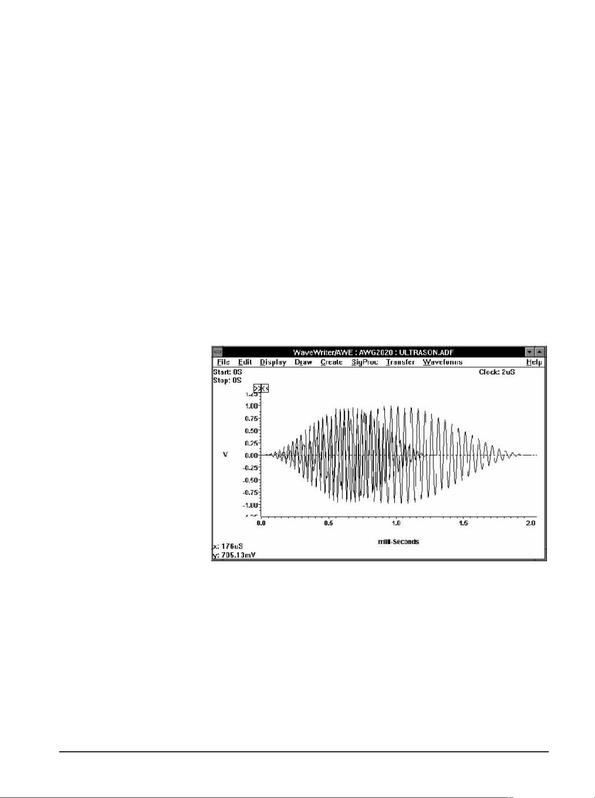
The waveform appears as shown in Figure 2Ć6.
WaveWriter (AWE) User Manual
Figure 2Ć6:ăWaveform Display Area
17. From the File menu select Save. Change the filename from ultra2.adf to
ultrason.adf".
18. Select OK.
19. In the Warning box, select YES to overwrite the existing file with the new
waveform.
Load two more waveforms from disk using the following steps:
20. From the File menu select Open.
2Ć17
Page 40

Tutorial
21. From the File Name list box scroll and select the sample.adf" file then
select OK. Associate it with the AWG 2020 (click AWG2020) on the
Associate Waveform with Instrument menu to follow. Select OK.
This time, since the clock rate conforms to the default clock rate, the waveĆ
form loads automatically and becomes the current waveform.
22. From the File menu select Open.
Select the decay.adf" file and associate it with the AWG 2020.
Again, the waveform loads successfully and becomes the current waveform.
Step 8: Autoscaling the Current Waveform
Loading the last two waveforms exceeded the vertical axis scale established
previously in Set Axis Ranges. Use the Autoscale Current Waveform function
to automatically alter the vertical and horizontal scales for optimum display
of the current waveform.
Perform the following steps to autoscale these waveforms:
1. From the Display menu select Autoscale Current Waveform.
2. Select At Middle of Waveform from the subĆmenu.
The vertical and horizontal ranges are automatically rescaled to accommoĆ
date the vertical height and record length of the current waveform.
Step 9: Zooming the Waveform
The Zoom In feature magnifies a portion of the Waveform Display Area. Use
this function to improve resolution and detail for drawing.
To zoom the waveform use the following steps:
1. From the Display menu select Zoom In.
The upper left hand corner of the zoom box becomes the cursor.
2. We will magnify the second cycle of decay.adf. To identify the region for
zooming, place the Cursor Coordinates readout at x: 378 ms, y: 3.53 V.
Press the LEFT mouse button and drag the lower right hand corner to
approximately x: 766 ms, y: 300 mV. Release the mouse button.
The region within the box is now magnified.
3. To return to the original display, select Zoom Out from the Display
menu.
2Ć18
Step 10: Changing the Current Waveform
Most WaveWriter functions operate on the current waveform. When you load
a new waveform from disk it automatically become the current waveform. To
designate another waveform as the current waveform, use one of the followĆ
ing methods:
Operating Basics
Page 41

Tutorial
1. From the Waveforms menu select a new waveform from the bottom of
the list (waveforms must be loaded to be listed). Note that the checked
waveform is the current waveform.
When you select a new waveform, the display color and title bar reflect its
status as the current waveform.
2. From the Waveforms menu select Waveforms Summary.
The Waveform Summary lists each waveform currently in memory. The
associated instrument, record length, and waveform type are displayed. The
waveform Type is either waveform (Norm) or envelope (Env). The current
waveform is highlighted as shown in Figure 2Ć7.
Figure 2Ć7:ăWaveform Summary List Box
3. DoubleĆclick on SAMPLE.ADF to identify it as the current waveform.
Note that the WaveWriter title bar changes to reflect your selection and
SAMPLE.ADF assumes the current waveform color.
4. Select OK to close the Waveforms Summary window.
Step 11: Changing Offset
This step briefly discusses the offset adjustment. In Lesson 2 you will enter
offsets and construct more complex waveforms.
Some instruments incorporate offset into the waveform data or retain an
offset external to the data. WaveWriter always incorporates the offset with
the data. As a result, what you see on the screen is always what is sent to
the instrument.
Use the Waveforms ³ Change Amplitude/Offset menu to alter the offset
incorporated into a waveform data set. In the Change Amplitude/Offset
dialog box, enter the desired offset in the Amplitude edit box and select OK.
WaveWriter (AWE) User Manual
2Ć19
Page 42

Tutorial
Step 12: Using Markers
Markers delimit segments of the waveform in the horizontal axis. For many
menu selections you have the option of using the entire waveform or only
the portion between and including the markers. The distance between the
markers can never exceed the maximum record length for the target instruĆ
ment. If the Start or Stop marker is dragged past this length, the correĆ
sponding marker will be moved with it.
Each marker has a flag attached to it at the top of the Waveform Display
Area. The Start marker flag is marked with the symbol uu" and the Stop
marker flag with tt".
The location of the markers is indicated by the Start and Stop readouts in the
upper left corner of the window.
Perform the following steps to move the markers:
1. To move the Start marker, click and drag on the flag with the uu". As
you drag the marker to the right, the Stop marker automatically moves
with it. If you move the Start marker back to the left, the Stop marker no
longer moves. Note that as you move the markers, the marker readouts
update.
2. To move the Stop marker, click and drag on the box with the tt".
NOTE
If it becomes difficult to position a marker to a specific point, use
the Display ³ Set Markers function. The Set Markers function
allows direct entry of point values for the markers.
Summary
You have just completed Lesson 1. In this lesson you learned how to:
H Start up WaveWriter
H Use the Help function
H Configure the target instrument
H Set the horizontal and vertical axis ranges
H Read waveforms from disk
H Autoscale the current waveform
H Zoom a portion of the current waveform
2Ć20
H Set and change waveform offsets
H Move markers and enter marker coordinates
Operating Basics
Page 43

Tutorial
Lesson 2
Creating and Saving
a TV Signal
Waveform
This lesson steps you through the creation of a television signal waveform
using various WaveWriter menu selections. In Lesson 2 we will learn to use:
H Create functions: Equation, Sine, and Pulse
H Draw functions: Autoline and Horizontal
H Edit functions: Copy Between Markers and Replace Between Markers
H SigProc functions: Add Scalar, Multiply by Scalar, and Multiply WaveĆ
forms
The waveform you will create is a NTCĆ7 composite test signal consisting of
the following five parts:
H Horizontal Blanking pulse
H Line Bar
H 2T Pulse
H Modulated SineĆSquared Pulse
H Modulated 5ĆRiser Staircase
Figure 2Ć8 shows the waveform you will create.
WaveWriter (AWE) User Manual
Figure 2Ć8:ăNTCĆ7 Composite Test Signal
2Ć21
Page 44

Tutorial
Step 1: Clear All Waveforms from WaveWriter Memory
To avoid confusing current waveforms with waveforms from previous sesĆ
sions, clear all waveforms from memory before proceeding. If there are
waveforms existing in memory from a previous session, you will be
prompted. If you wish to save prior data select Yes . Otherwise, select No.
Perform the following steps to clear the memory:
1. From the Waveforms menu select Clear Waveform(s).
The Clear Waveform(s) dialog box appears.
2. Select the All Waveforms button.
NOTE
Clear Waveform(s) is grayed and unavailable if there are no waveĆ
forms in memory. If there are altered waveforms in memory not
previously saved, you are given the option to save them before
deleting them.
Step 2: Change the Default Target Instrument to the
AWG 2020
Perform the following steps to designate the target instrument:
1. From the Waveforms menu select Associate Waveform.
The Associate Waveform with Instrument dialog box appears.
2. Select the AWG2020" defined in Lesson 1 from the Instrument List.
3. Select OK.
4. If you are warned that the current clock rate is invalid for the newly
selected target instrument, select OK to accept the clock rate offered.
Note that the WaveWriter title bar displays AWG2020 as the target instruĆ
ment.
Step 3: Change the Clock Rate
Perform the following steps to change the clock rate:
1. From the Waveforms menu select Change Clock Rate.
The AWG2020 Clock Rate dialog box appears.
2Ć22
2. Enter 34.9n" in the Time per Point edit box.
3. Select OK.
The Clock readout (just below Help in the Menu Bar) indicates the new clock
rate: 34.9nS.
Operating Basics
Page 45

Tutorial
Step 4: Create a New Waveform
Perform the following steps to create a new waveform:
1. From the File menu select New.
The Associate New Waveform with Instrument dialog box appears.
2. Select OK to associate the new waveform with the AWG 2020.
The associate waveform dialog box is replaced by the New dialog box.
3. Enter Lesson2" in the New Waveform Name edit box. This is the name
of our new waveform.
4. Select the Seconds option button.
5. Enter 63.6576u" in the Record Length edit box.
6. Select OK.
The waveform Lesson2" is created at 0 Volts. This waveform becomes the
current waveform as noted in the title bar.
Step 5: Set Up the Axis to Display the Desired Amplitude
and Record Length
Perform the following steps to configure the axis ranges for the new waveĆ
form:
1. From the Display menu select Set Axis Ranges.
The Set Axis Ranges dialog box appears.
2. In the Vertical group, select the Ampl/Offset option button.
3. In the Amplitude: (PkĆPk) edit box enter 2".
4. In the Offset edit box enter 0".
5. In the Horizontal group, select the Seconds option button.
6. In the Start edit box enter 0".
7. In the Stop edit box enter 63.6227u".
8. Select OK.
The vertical and horizontal axis ranges are now set to display the new waveĆ
form.
WaveWriter (AWE) User Manual
Step 6: Create the Horizontal Blanking Pulse
The first portion of the NTC waveform we are creating is the Blanking pulse.
Perform the following steps to create the pulse:
1. From the Display menu select Zoom In.
The leftĆhand corner of the zoom box becomes the cursor.
2Ć23
Page 46

Tutorial
2. Using the Cursor/Crosshair Coordinate readouts, place the corner at
approximately x: 0 s, y: 350 mV. Press the LEFT mouse button and drag
the cursor to approximately x: 6.9 ms, y: -720 mV. Release the mouse
button.
The region within the box is magnified.
3. From the Draw menu select Horizontal.
4. Position the cursor at approximately x: 1.54 ms, y: -287.5 mV (±10 mV).
Click the LEFT mouse button and drag to x: 6.42 ms. (Note that as you
drag the mouse, the horizontal line always stays at the original voltage
selected.) Release the LEFT mouse button to end the line segment.
Press the RIGHT mouse button to redraw the display.
NOTE
If you experience difficulty in positioning the cursor to an exact
location, use the mouse for coarse adjustment and the arrow keys
for fine the adjustment. If an error is created, use the Edit ³ Undo
function to delete the operation, then start over.
5. From the Display menu select Zoom Out.
6. From the Create menu select Sine.
The Sine dialog box appears as shown in Figure 2Ć9.
7. In the Vertical group, select the Ampl/Offset option button.
8. In the Amplitude: (PkĆPk) edit box enter 287.5m".
9. In the Offset edit box enter 0".
10. In the Horizontal group, select the Seconds option button.
11. Select the Cycles check box if it is not empty
Note that the Calculate button changes to Calculate Cycles. This parameter
will be calculated based on the Start Point, Stop Point, Frequency, and
current clock rate.
12. In the Start Point edit box enter 6.98u".
13. In the Stop Point edit box enter 9.42u".
14. In the Frequency edit box enter 3.586M".
15. Select the Calculate Cycles button.
Cycles is updated based on the parameters entered. The value should be
8.89.
2Ć24
16. In the Phase edit box enter 0".
17. In the Action group, select the Replace option button.
Operating Basics
Page 47

The Sine dialog box appears as shown in Figure 2Ć9.
Tutorial
Figure 2Ć9:ăSine Dialog Box
18. Select OK to create the Blanking Pulse.
19. From the Display menu select Zoom In, to magnify the waveform
created so far.
WaveWriter (AWE) User Manual
2Ć25
Page 48

Tutorial
The waveform should be similar to that shown in Figure 2Ć10.
20. From the Display menu select Zoom Out to return to the original disĆ
play.
Figure 2Ć10:ăHorizontal Blanking Pulse
Step 7: Create the Line Bar
The second portion of the NTC waveform we are creating is the Line Bar.
Perform the following steps to add the Line Bar to the existing waveform:
1. From the Create menu select Pulse.
The Pulse Wave dialog box appears.
2. In the Vertical group: enter 714.3m" in the Maximum edit box, 0" in the
Minimum edit box.
3. In the Action group, select the Replace option button.
4. In the Horizontal group, select the Seconds option button.
5. Select the Period check box if it is not empty
6. In the Start Point edit box enter 11.31u".
7. In the Stop Point edit box enter 29.73u".
8. In the Cycles edit box enter 1".
9. In the Delay edit box enter 0".
2Ć26
10. In the Pulse Width (50%) edit box enter 18.15u".
Operating Basics
Page 49

Tutorial
11. In the Transitions (10% - 90%) group, select the Pulse Direction: Pos
option button.
12. In the Risetime edit box enter 104.7n"
13. In the Falltime edit box enter 104.7n"
14. Select both Ramp option buttons.
The completed Pulse Wave dialog box should appear as shown in FigĆ
ure 2Ć11.
WaveWriter (AWE) User Manual
Figure 2Ć11:ăPulse Wave Dialog Box
15. Select OK to add the Line Bar to the waveform.
The Line Bar should be identical to the positiveĆgoing 700 mV pulse beginĆ
ning at approximately .01 ms and ending at .03 ms, as shown in Figure 2Ć8.
Step 8: Create a 2T Pulse
The third portion of the NTC waveform is the 2T pulse. Perform the following
steps to add the pulse to the existing waveform:
1. From the Create menu select Equation.
The Equation dialog box appears.
2. Select the Library button at the bottom of the dialog box.
The equation library dialog box appears.
2Ć27
Page 50

Tutorial
3. Scroll and select the 2T" pulse entry by doubleĆclicking on it.
The Equation dialog box is redisplayed with the selected 2T pulse equation
entered in the Equation edit box.
4. Select the Seconds option button.
5. In the Horizontal group, enter 33.923u" in the Start Point edit box.
6. Enter 34.551u" in the Stop Point edit box.
7. In the Action group, select the Replace option button.
The Equation dialog box should be identical to Figure 2Ć12.
Figure 2Ć12:ăEquation for 2T Pulse
8. Select OK to add the 2T pulse to the waveform.
9. From the Display menu, select Zoom In to magnify the region just
created.
2Ć28
Operating Basics
Page 51

The 2T Pulse should be identical to Figure 2Ć13.
Tutorial
Figure 2Ć13:ă2T Pulse Display
10. Select the Display menu function Zoom Out to return to the original
display.
Step 9: Create the Modulate Sine Squared Pulse
The fourth portion of the NTC waveform is the Sine Squared pulse. We will
build the modulated sine squared pulse by creating two individual waveĆ
forms, multiply them together, then copy the result into the Lesson2 waveĆ
form.
Steps 1 through 5 below can be accomplished in a single step with the
Modsin2 equation. However, to demonstrate the SigProc and Edit functions,
we will forgo the most direct method.
Perform the following steps to add the Sine Squared pulse to our waveform:
1. From the Create menu select Equation.
The Equation dialog box appears.
2. Select the Library button at the bottom of the dialog box.
The equation library dialog box appears.
WaveWriter (AWE) User Manual
3. Scroll and select the sin2" entry by doubleĆclicking on it.
The Equation dialog box is redisplayed with the selected Sin2 equation
entered in the Equation edit box.
4. In the Horizontal group, enter 0" in the Start Point edit box.
2Ć29
Page 52

Tutorial
5. Enter 3.385u" in the Stop Point edit box.
6. In the Action group, select the New Waveform option button.
7. Enter Sin2" in the Waveform Name edit box.
8. Select OK.
The Associate Waveform with Instrument dialog box appears.
9. Select OK to associate the new waveform with the AWG 2020.
The Sine Squared waveform is then created starting at time zero.
10. From the Create menu select Equation.
The Equation dialog box appears.
11. Select the Library button at the bottom of the dialog box.
The equation library dialog box appears.
12. Scroll and select the carrier" entry by doubleĆclicking on it.
The Equation dialog box is redisplayed with the selected carrier equation
entered in the Equation edit box.
13. In the Action group, select the New Waveform option button.
14. Enter Carrier" in the Waveform Name edit box.
Notice that the Start and Stop points remain the same as the previous step.
15. Select OK.
The Associate Waveform with Instrument dialog box appears.
16. Select OK to associate the new waveform with the AWG 2020.
The Carrier waveform is then created starting at time 0.
We will now offset the carrier and scale it back to 1 V.
17. From the SigProc menu Add Scalar.
The Add Scalar dialog box appears.
18. Enter 1" in the Add Scalar edit box.
19. In the Processing Region group, select the Entire Waveform option
button.
20. Select OK.
21. From the SigProc menu select Multiply by Scalar.
The Multiply Current Waveform by Scalar dialog box appears.
2Ć30
22. Enter .5" in the Multiply by Scalar edit box.
23. In the Processing Region group, select the Entire Waveform option
button.
24. Select OK.
Operating Basics
Page 53

Tutorial
25. From the SigProc menu select Multiply Waveforms.
The Multiply Waveforms dialog box appears.
26. DoubleĆclick on the Carrier" entry in the Displayed Waveforms list box.
The Wfm 1 edit box reflects the entry: Carrier.
27. DoubleĆclick on the Sin2" entry in the Displayed Waveforms list box.
The Wfm 2 edit box reflects the entry: Sin2.
28. Click on the Wfm 3 edit box and enter Modsin2". The product of the two
waveforms will be called Modsin2.
29. Select OK.
The Associate Waveform with Instrument dialog box appears.
30. Select OK to associate the new waveform with the AWG 2020. Modsin2
is now the current waveform.
31. From the SigProc menu select Multiply by Scalar.
The Multiply Current Waveform by Scalar dialog box appears.
32. Enter .7143" in the Multiply by Scalar edit box.
33. Select OK.
34. From the Display menu select Zoom In. Magnify the region between
approximately x: 0 s, y: 700 mV and x:4.26 ms, y: -100 mV.
35. Move the Start Marker to0s.
36. Move the Stop Marker to 3.385 ms (the end of the Modsin2 waveform).
37. From the Edit menu select Copy Between Markers.
This copies the current waveform data from Modsin2 into the edit buffer.
38. Remove the three waveforms we just created from memory: from the
Waveforms menu select Clear Waveform(s).
The Clear Waveform(s) list box appears.
39. Select the Sin2 entry.
40. Press and hold the [CTRL] key.
41. Select the Carrier entry.
42. Select the Modsin2 entry.
43. Release the [CTRL] key and select OK.
WaveWriter (AWE) User Manual
For each selection, you are warned that you have not saved the waveform
and given the opportunity to save it. Select No for each option. We no
longer need these waveforms.
44. From the Display menu select Zoom In. Magnify the region between
approximately x: 36 ms, y: 750 mV and x: 42 ms, y: -100 mV.
2Ć31
Page 54

Tutorial
45. Move the Start Marker to 37.413 ms.
46. Move the Stop Marker to 40.833 ms.
47. From the Edit menu select Replace Between Markers.
The contents of the edit buffer, containing the Modulated Sine Squared
Pulse, are inserted into the current waveform between the markers.
The displayed waveform appears as shown in Figure 2Ć14.
Figure 2Ć14:ăModulated Sine Squared Pulse
48. To return to the original display, select Zoom Out from the Display
menu.
Step 10: Create the Modulated 5ĆRiser Staircase Test Signal
The last portion of the NTC waveform we are creating is the Staircase.
Perform the following steps to add the staircase to the existing waveform:
1. From the Create menu select Sine.
The Sine dialog box appears. Some values entered previously are retained.
H In the Horizontal group, enter 42.9968u" in the Start Point edit box.
H In the Stop Point edit box enter 49.4886u.
H In the Frequency edit box enter 3.581662M".
H Select Calculate Cycles.
2Ć32
Operating Basics
Page 55

Tutorial
When completed, the dialog box should be identical to that shown in FigĆ
ure 2Ć15. If not, correct any discrepant items.
Figure 2Ć15:ăSine Dialog Box
2. Select OK to generate the first step.
3. From the Create menu select Sine.
The Sine dialog box appears.
H In the Vertical group, enter 128.6m" in the Offset edit box.
H In the Horizontal group, enter 49.523u" in the Start Point edit box
H Enter 9.125" in the Cycles edit box.
H Select the Calculate Stop Point button to see the resulting Stop Point.
4. Select OK to generate the second step.
5. From the Create menu select Sine.
The Sine dialog box appears.
H In the Vertical group, enter 257.1m" in the Offset edit box.
H In the Horizontal group, enter 52.07u" in the Start Point edit box
6. Select OK to create the third step.
WaveWriter (AWE) User Manual
7. From the Create menu select Sine.
The Sine dialog box appears.
H In the Vertical group, enter 385.7m" in the Offset edit box.
H In the Horizontal group, enter 54.617u" in the Start Point edit box.
8. Select OK to generate the fourth step.
2Ć33
Page 56

Tutorial
9. From the Create menu select Sine.
The Sine dialog box appears.
H In the Vertical group, enter 514.3m" in the Offset edit box.
H In the Horizontal group, enter 57.164u" in the Start Point edit box.
10. Select OK to generate the fifth step.
11. From the Create menu select Sine.
The Sine dialog box appears.
H In the Vertical group, enter 642.9m" in the Offset edit box.
H In the Horizontal group, enter 59.714u" in the Start Point edit box.
Select OK to add the final step and complete the Modulated 5ĆRiser StairĆ
case waveform.
12. From the Display menu select Zoom In to magnify the region between
approximately x: 60 ms, y: 800 mV and x: 63.65 ms, y: -100 mV.
13. From the Draw menu select Autoline to draw the final line of the waveĆ
form.
14. Position the cursor at x: 62.26 ms, y:714.3 mV (±10 mV).
15. Click the LEFT mouse button and let up.
16. Move the cursor to x: 63.45 ms, y: 714.3 mV.
17. Click the LEFT mouse button and let up to end the line segment.
18. Press the RIGHT mouse button to redraw the screen.
19. Select the Display menu function Zoom Out.
20. Select the Display menu function Zoom In to magnify the 5ĆRiser stairĆ
case region just created (from approximately x: 42 ms, y: 800 mV to
x: 63 ms, y: -200 mV).
2Ć34
Operating Basics
Page 57
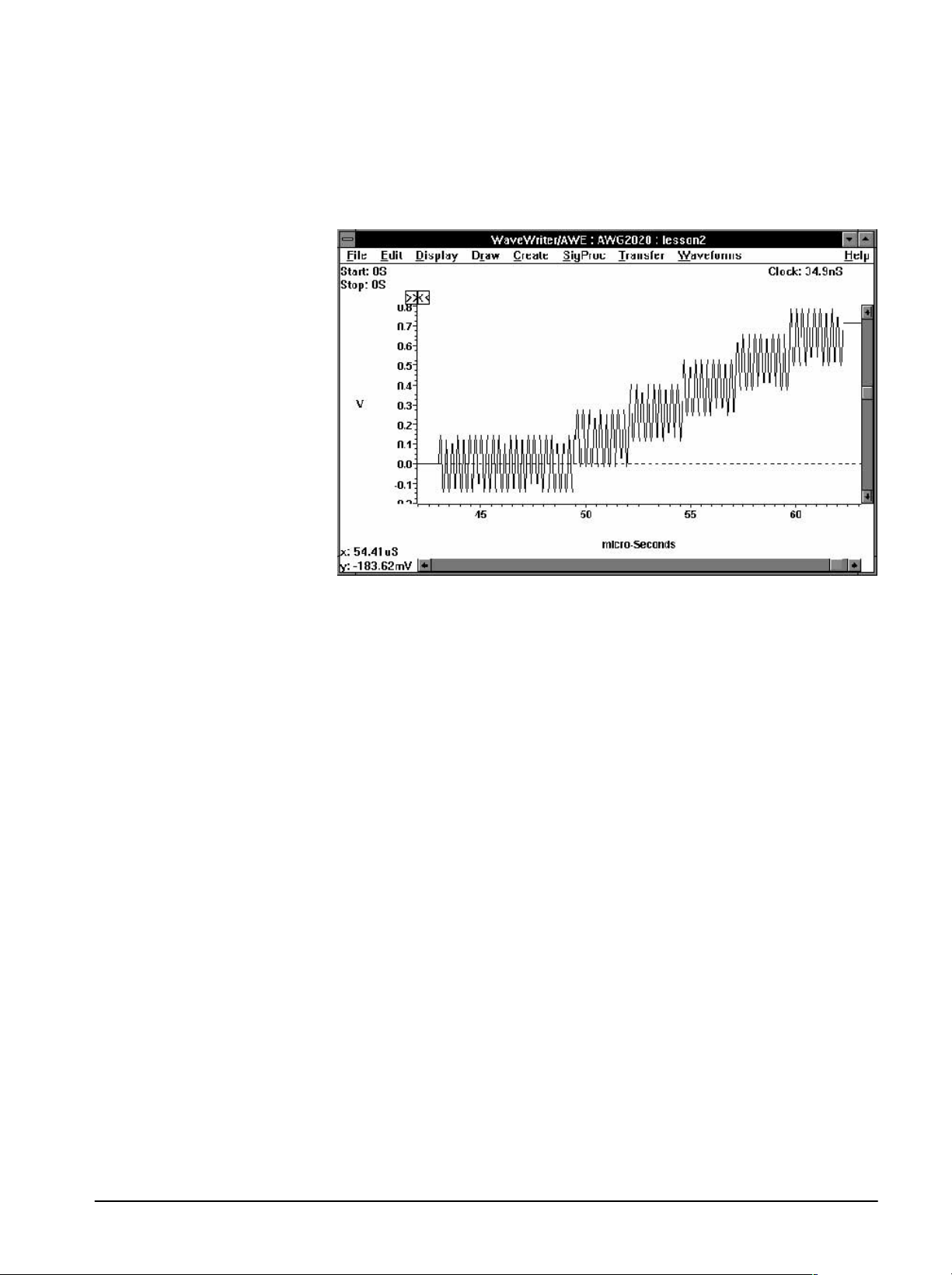
The staircase portion of the NTC waveform should appear as shown in
Figure 2Ć16.
Tutorial
Figure 2Ć16:ă5ĆRiser Staircase
21. Select the Display menu function Zoom Out to return to the original
display.
The NTCĆ7 composite test signal is now complete.
Step 11: Save the Waveform as an ADIF file
To save the NTCĆ7 composite waveform, complete the following steps:
1. From the File menu select Save.
The Save As dialog box appears.
The name you entered previously, Lesson 2, appears as the default name in
the File Name edit box.
2. Scroll and select ADIF 1.0" from the Save File as Type list box at the
bottom left.
3. Select OK.
The file LESSON2.ADF is now saved.
WaveWriter (AWE) User Manual
Step 12: Load File NTCĆ7.ADF and Compare Results
To check the accuracy of the composite waveform created in Lesson 2,
compare it to the reference waveform (NTCĆ7.ADF) stored in memory.
2Ć35
Page 58

Tutorial
To recall the reference waveform from memory:
1. From the File menu select Open.
The Open list box appears.
2. In the File Name list box, scroll and doubleĆclick on the ntcĆ7.adf" entry.
The Associate Waveform with Instrument dialog box appears.
3. Select OK to associate the waveform with the AWG 2020.
The NTCĆ7 reference waveform is loaded from memory and displayed as the
current waveform in WaveWriter. The waveform should closely match the
Lesson2 waveform just created, if the tutorial was followed correctly. The
waveform also appears as Figure 2Ć8 on Page 2Ć21.
Summary
You have just completed Lesson 2. In this lesson you learned how to:
H Compose a complex waveform
H Use the Create functions: Equation, Sine, Pulse
H Select and incorporate waveforms from the library
H Use the Autoline and Horizontal Draw functions
H Copy between and replace between markers
H Use the AutoĆcalculate functions
H Add and multiply a waveform by Scalar
H Multiply a waveform
H Save a waveform
H Load a waveform from memory
2Ć36
Operating Basics
Page 59

Tutorial
Lesson 3
Working with an
AWG 2020 Arbitrary
Waveform Generator
Lesson 3 demonstrates the Acquire and Send functions for the AWG 2020.
In this lesson you will load a waveform from disk, change the clock rate, and
send the waveform to the Arbitrary Waveform Generator (AWG). You will
then reacquire the waveform from the instrument to verify its accuracy.
Step 1: Clear All Waveforms from WaveWriter Memory
To avoid confusing current waveforms with waveforms from previous sesĆ
sions, clear all waveforms from memory before proceeding. If there are
waveforms existing in memory from a previous session, you will be
prompted. If you wish to save prior data select Yes . Otherwise, select No.
Perform the following steps to clear the memory:
1. From the Waveforms menu select Clear Waveform(s).
The Clear Waveform(s) dialog box appears.
2. Select the All Waveforms button.
NOTE
Clear Waveform(s) is grayed and unavailable if there are no waveĆ
forms in memory. If there are altered waveforms in memory not
previously saved, you are given the option to save them before
deleting them.
Step 2: Change the Target Instrument
Perform the following steps to designate the target instrument:
1. From the Waveforms menu select Associate Waveform.
The Associate Waveform with Instrument dialog box appears.
2. From the Instrument list select AWG2020". (The name you select must
identify the device driver wawg2020.drv" in the Transfer ³ ConfigĆ
ure Instrument list box).
3. Select OK.
4. If you are warned that the current clock rate is invalid for the newly
selected target instrument, select Yes to accept the clock rate offered.
The WaveWriter title bar denotes the AWG 2020 as the target instrument.
Step 3: Change the Clock Rate
Perform the following steps to set the clock rate:
1. From the Waveforms menu select Change Clock Rate.
The AWG2020 Clock Rate dialog box appears.
WaveWriter (AWE) User Manual
2Ć37
Page 60

Tutorial
2. Enter 2u" in the Time per Point edit box.
3. To see the corresponding Frequency value, press the [TAB] or [ENTER]
key. The edit box will update with the equivalent value.
4. Select OK.
The Clock readout indicates the new clock rate.
Step 4: Open a New File
To open a new file perform the following steps:
1. From the File menu select Open.
The Open dialog box appears.
2. In the Directories list box doubleĆclick awe4\sample.IntheFile Name
list box scroll and select the sample.adf" file.
3. Select OK.
The Associate Waveform with Instrument dialog box appears.
4. Select OK to associate the new waveform with the AWG 2020.
The waveform is loaded from disk into WaveWriter memory and becomes
the current waveform, as noted in the title bar.
2Ć38
Operating Basics
Page 61

Tutorial
Step 5: Scale the Waveform
To maximize bit resolution when transferring the waveform to the AWG 2020,
scale the waveform as outline:
1. From the Display menu select Autoscale Current Waveform. From the
subĆmenu select At Zero Volts.
Note the change in the vertical and horizontal axis scales. The waveform
appears as shown in Figure 2Ć17.
Figure 2Ć17:ăSAMPLE.ADF Display
Step 6: Send the Waveform to the AWG 2020
To transfer the waveform to the AWG 2020 Arbitrary Waveform Generator:
1. From the Transfer menu select Send.
The Send AWG 2020 dialog box appears as shown in Figure 2Ć18.
NOTE
If the AWG 2020 is not at the GPIB address shown in the Transfer
³ Configure Instrument dialog box, a warning stating No
AWG 2020 found on the bus" is displayed. Change the address in
the Configure Instrument dialog box, and then try again.
Alternatively, change the AWG's GPIB address (using the instruĆ
ment's UTILITY menu) and then try again.
WaveWriter (AWE) User Manual
2Ć39
Page 62

Tutorial
Figure 2Ć18:ăAWG2000 Send Waveform Dialog Box
2. Select OK to accept the default entries.
The waveform is sent to the specified channel and displayed on the
AWG 2020 screen.
NOTE
The dialogs are very similar for all instruments in the AWG 2000
series. Do not be confused by this; if you configured the wrong
type of instrument in the Configure Instrument dialog box, WaveWĆ
riter will not be able to find the instrument. If the AWG2000 Send
Waveform dialog successfully displays, you can be confident that
the correct instrument type has been configured.
Step 7: Acquire the Waveform Back
To reacquire the waveform from the instrument and verify its accuracy:
1. From the Transfer menu select Acquire.
The Acquire Waveform dialog box appears listing all instruments previously
configured.
2. DoubleĆclick on the AWG2020".
2Ć40
The Acquire AWG 2020 dialog box appears.
3. In the Source group, Waveform Name edit box, enter CH1".
4. In the Destination group select the Create New Waveform option button.
5. Enter Lesson3" in the Waveform Name edit box.
Operating Basics
Page 63

The dialog box appears as shown in Figure 2Ć19.
Tutorial
Figure 2Ć19:ăAWG2000 Acquire Waveform Dialog Box
6. Select OK.
The waveform is reacquired from the selected source and becomes the
current waveform. The two waveforms appearing in the Waveform Display
Area should be identical.
Summary
You have just completed Lesson 3. In this lesson you learned how to:
H Associate a waveform
H Set the clock rate
H Load a waveform from disk
H Scale the waveform
H Transfer a waveform to the AWG 2020 with the Send command
H Acquire a waveform from the AWG 2020 with the Acquire command
WaveWriter (AWE) User Manual
2Ć41
Page 64

Tutorial
Lesson 4
Working with a
TDS 500 Series
Digitizing
Oscilloscope
In Lesson 4 you will modify the envelope of a nonenveloped waveform. You
will then send the newly created (enveloped) waveform, along with the
original normal waveform, to the oscilloscope reference memory.
Step 1: Clear All Waveforms from WaveWriter Memory
To avoid confusing current waveforms with waveforms from previous sesĆ
sions, clear all waveforms from memory before proceeding. If there are
waveforms existing in memory from a previous session, you will be
prompted. If you wish to save prior data select Yes . Otherwise, select No.
Perform the following steps to clear the memory:
1. From the Waveforms menu select Clear Waveform(s).
The Clear Waveform(s) dialog box appears.
2. Select the All Waveforms button.
NOTE
Clear Waveform(s) is grayed and unavailable if there are no waveĆ
forms in memory. If there are altered waveforms in memory not
previously saved, you are given the option to save them before
deleting them.
Step 2: Change the Target Instrument
Perform the following steps to designate the target instrument:
1. From the Waveforms menu select Associate Waveform.
The Associate Waveform with Instrument dialog box appears.
2. From the Instrument List select TDS500". (The name you select must
identify the device driver wtds500a.drv" in the Transfer ³ Configure
Instrument list box.)
NOTE
If you have not configured the TDS 500 Series oscilloscope from
within WaveWriter, see Lesson 1. Use the instructions for configurĆ
ing the AWG 2020, using wtds500a.drv as the device driver.
3. Select OK.
4. If you are warned that the current clock rate is invalid for the newly
selected target instrument, select Yes to accept the clock rate offered.
The WaveWriter title bar denotes the TDS 500 as the target instrument.
2Ć42
Operating Basics
Page 65

Tutorial
Step 3: Change the Clock Rate
Perform the following steps to set the clock rate:
1. From the Waveforms menu select Change Clock Rate.
The TDS Series Clock Rate dialog box appears.
2. Enter 2m" in the Time per Division edit box.
3. To see the corresponding Time per Point and Frequency values, press
the [TAB] or [ENTER] key. The edit boxes will update with the equivaĆ
lent values.
The dialog box appears as shown in Figure 2Ć20.
WaveWriter (AWE) User Manual
Figure 2Ć20:ăTDS Series Clock Rate Dialog Box
4. Select OK.
The Clock readout indicates the new clock rate.
NOTE
The appearance of the TDS Series Clock Rate dialog is the same
for all TDS series scopes. Do not be confused by this; provided you
carried out Step 2 in this tutorial correctly, WaveWriter knows that
your waveform is associated with a TDS 500 type of scope. If you
think that you have made a mistake, check that the driver
'wtds500a.drv' is displayed against the name 'TDS500' in the
Configure Instrument dialog box, and correct as necessary. Also,
check that the name 'TDS500' is displayed in the title bar of the
WaveWriter main window, and use the Waveforms ³ Associate
Waveform selection to associate the waveform with the instrument
named 'TDS500' if necessary.
2Ć43
Page 66

Tutorial
Step 4: Open a New File
To open a new file perform the following steps:
1. From the File menu select Open.
The Open dialog box appears.
2. In the Directories list box doubleĆclick awe4\sample.IntheFile Name
list box, scroll and select the square.adf" file.
3. Select OK.
The Associate Waveform with Instrument dialog box appears.
4. From the Display group, select the Autoscale at middle of Wfm option
button.
5. Select OK to associate the new waveform with the TDS 500.
The waveform is loaded from disk into WaveWriter memory and becomes
the current waveform, as noted in the title bar.
The Waveform appears as shown in Figure 2Ć21.
2Ć44
Figure 2Ć21:ăSQUARE.ADF Display
Operating Basics
Page 67

Tutorial
Step 6: Create an Envelope Waveform
To create an enveloped waveform perform the following steps:
1. From the Create menu select Envelope Tolerance.
The Envelope Tolerance dialog box appears.
2. In the Output Envelope edit box enter ENVELOPE".
3. In the Vertical Tolerance group, select the Percentage [Peak to Peak]
option button.
4. In the Maximum Tolerance edit box enter 10".
5. In the Minimum Tolerance edit box enter 15".
6. In the Horizontal Tolerance group edit box enter 5".
The dialog box appears as shown in Figure 2Ć22.
WaveWriter (AWE) User Manual
Figure 2Ć22:ăEnvelope Tolerance Dialog Box
7. Select OK.
WaveWriter computes the waveform maximum and minimum values and
creates the upper limit of the waveform using a 10% vertical tolerance and
the lower limit using a 15% vertical tolerance. For the horizontal tolerance,
each waveform point will be shifted left and right by 5 points, creating a
band 10 points wide. ENVELOPE becomes the current waveform.
8. From the Display menu select Autoscale Current Waveform. From the
subĆmenu select At Zero Volts.
2Ć45
Page 68

Tutorial
The Waveform appears as shown in Figure 2Ć23.
Figure 2Ć23:ăSQUARE.ADF and ENVELOPE Display
Step 7: Send the Envelope Waveform to the TDS 500
To transfer the ENVELOPE waveform to the TDS 500 oscilloscope:
1. From the Transfer menu select Send.
The Send TDS Scope dialog box appears.
NOTE
If the TDS 500 is not at the GPIB address shown in the Transfer ³
Configure Instrument dialog box, a warning stating No TDS 500
on GPIB 0 address..." is displayed. Select Search all addresses"
to have WaveWriter search all addresses for the instrument.
2. Select the Send Waveform option button.
3. In the Location group, select the REF1 option button.
4. In the Partial Envelope group, click the Allocate Reference Memory
check box and set the memory allocation to 2500.
2Ć46
Operating Basics
Page 69

The dialog box appears as shown in Figure 2Ć24.
Tutorial
Figure 2Ć24:ăSend - TDS Scope Dialog Box
5. Select OK to initiate the transfer.
The envelope waveform is sent to the oscilloscope reference memory locaĆ
tion 1 and displayed on screen.
NOTE
The dialogs are very similar for all instruments in the TDS series. Do
not be confused by this; if you configured the wrong type of instruĆ
ment in the Configure Instrument dialog box, WaveWriter will not be
able to find the instrument. If the Send - TDS Scope successfully
displays, you can be confident that the correct instrument type has
been configured.
WaveWriter (AWE) User Manual
2Ć47
Page 70

Tutorial
Step 8: Send the Original Waveform to the Instrument
To transfer the SOUARE.ADF waveform to the TDS 500 oscilloscope:
1. Identify the new current waveform" by selecting SQUARE.ADF from the
bottom of the Waveforms menu.
2. From the Transfer menu select Send.
The Send TDS Scope dialog box appears.
3. In the Location group select the REF2 option button.
4. Select OK to initiate the transfer.
The original waveform is sent to the oscilloscope reference memory location
2 and displayed on screen.
Manually adjust the TDS 500 to accommodate the onĆscreen display of the
two waveforms.
Summary
You have just completed Lesson 4. In this lesson you learned how to:
H Associate a waveform
H Set the clock rate
H Load a waveform from disk
H Associate the waveform
H Scale the waveform
H Envelope a waveform
H Transfer two waveforms to the TDS 500 with the Send command. Each
waveform was sent to a different memory location.
2Ć48
Operating Basics
Page 71

Reference
Page 72

Page 73

Menu Map
The Menu Map lists the WaveWriter menu selections. Use the map as a
reference to the WaveWriter functions. Menus are listed as they appear in
the Menu Bar across the top of the Waveform Display Area. The Reference
sections to follow discuss each WaveWriter menu in detail.
File
New...
Open...
Save...
Import...
Export...
Hardcopy...
Exit
About...
Edit
Undo
Disable Undo
Cut Between Markers
Copy Between Markers
Delete Between Markers
Insert at Start Marker
Replace Between Markers
Append to End of Waveform
Flip Horizontal Between Markers
Flip Vertical Between Markers
Horizontal Resolution...
Vertical Resolution...
WaveWriter (AWE) User Manual
3Ć1
Page 74

Menu Map
Display
Redraw Dot
Redraw Vector
Zoom In
Zoom Out
Zoom Between Markers
Set Axis Ranges...
Set Markers
Autoscale Current Waveform
At Zero Volts
At Given Volts...
At Middle of Wfm
Horizontal Axis
Show Crosshairs
Show Multiple Waveforms
Set Colors and Line Styles...
Draw
Nodraw
Freehand
Horizontal
Vertical
Autoline
Envelope Max Don't Care
Envelope Min Don't Care
Envelope Max
Envelope Min
Create
Equation...
Sine...
Triangle...
Pulse...
Square...
Envelope Tolerance...
Envelope Couple...
Envelope Decouple...
SigProc
3Ć2
Add Scalar...
Multiply by Scalar...
Add Waveforms...
Subtract Waveforms...
Multiply Waveforms...
Divide Waveforms...
Reference
Page 75

Transfer
Configure Instruments...
Acquire...
Send...
Waveforms
Change Clock Rate...
Change Amplitude/Offset...
Associate Waveform...
Rename Waveform...
Clear Waveform(s)...
Waveform Summary...
Waveform Detail
Help
WaveWriter (AWE) User Manual
3Ć3
Page 76

Menu Map
3Ć4
Reference
Page 77

File Operations
Use the following File menu selections to create, open, store, or print waveĆ
forms or to end a WaveWriter session:
H New Ċ Creates a new waveform file
H Open Ċ Opens an existing native format waveform file
H Save Ċ Stores a waveform native format file
H Import Ċ Opens an existing foreign format waveform file
H Export Ċ Stores a waveform in a foreign format waveform file
H Hardcopy Ċ Outputs the current waveform display to a printing device
H Exit Ċ Ends the WaveWriter session
H About Ċ Identifies the installed version of WaveWriter
New
Use the New menu selection to create a new or envelope waveform. When
you select New from the File menu, the dialog box in Figure 3Ć1 appears.
WaveWriter (AWE) User Manual
Figure 3Ć1:ăAssociate New Waveform with Instrument Dialog Box
3Ć5
Page 78

File Operations
Use the Associate New Waveform with Instrument dialog box to associate
an instrument with the new waveform and to define the amplitude and offset
used in the display area.
Instrument List Ċ Associate the new waveform with a target instrument
by making a selection from the list.
Max/Min Ċ Enter the desired highest and lowest voltage levels for the
vertical display. Values should not be greater than those allowed by the
target instrument.
Amplitude (PkĆPk) Ċ Enter the peakĆtoĆpeak vertical display voltage in
the Amplitude edit box. Values should not exceed those allowed by the
target instrument.
Offset Ċ Enter the vertical external offset voltage in the Offset edit box.
Values should not exceed those allowed by the target instrument.
OK Ċ Associate the specified instrument with the new waveform. When the
New dialog box (Figure 3Ć2) is completed in the next step, the display is
adjusted to the parameters specified in the dialog box.
Cancel Ċ Select Cancel to abort the current operation and return to the
main menu.
Help Ċ Select Help to display information relating to this menu selection.
Use the scroll bar, if present, to read the entire Help text. To return to the
previous dialog box, select the ControlĆmenu box, then select Close.
3Ć6
Figure 3Ć2:ăNew Dialog Box
Reference
Page 79

File Operations
New Waveform Name Ċ Enter the name of the waveform you are creatĆ
ing in this edit box. The eight character file name and three character extenĆ
sion can be a combination of characters acceptable to the DOS system.
Certain reserved words are not permitted: aux, con, prn, nul, com1, com2,
com3, com4, lpt1, lpt2, lpt3. A file name extension is not necessary since it
is appended automatically when the waveform is saved to a disk file. If you
choose to add an extension, use any three DOSĆacceptable characters. The
Save menu description (to follow) discusses recommended file extension
nomenclature.
Record Length Ċ In this edit box, enter the length of the waveform. SpeciĆ
fy either Points or Seconds. The minimum length is two points and the
maximum length depends on memory availability, with an upper limit of 4 M
points for display. If you select Seconds, the number of points is based on
the current clock rate.
Type Ċ Select the basic file type you wish to create. You can create a
normal or an envelope waveform.
H Normal Waveform Ċ A normal" waveform is any nonenvelope waveĆ
form.
H Envelope Ċ An envelope waveform is a waveform that simultaneously
defines upper and lower limits horizontally and vertically.
OK Ċ Select OK to create the new waveform. (The new waveform becomes
the current waveform.) For normal waveforms, all points are initialized at the
external offset given in the Associate New Waveform with Instrument dialog
box. For envelope waveforms, the maximum (upper limit) waveform is set to
the maximum value of the Waveform Display Area; the minimum (lower limit)
waveform is set to the minimum value of the work area. Envelopes are filled
with a crosshatch pattern.
Cancel Ċ Select Cancel to abort the current operation and return to the
main menu.
Help Ċ Select Help to display information relating to this menu selection.
Use the scroll bar, if present, to read the entire Help text. To return to the
previous dialog box, select the ControlĆmenu box, then select Close.
WaveWriter (AWE) User Manual
3Ć7
Page 80

File Operations
Open
The Open command retrieves an existing waveform file from disk and loads
it as the current waveform. You can open a file created by WaveWriter in
ADIF, ISF, or CSV format. You can also open files created by other systems
using a compatible version of the ADIF format (.99 or 1.0 SCPI 1992). SelectĆ
ing Open from the File menu displays the dialog box in Figure 3Ć3.
Figure 3Ć3:ăOpen Dialog Box
File Name Ċ Enter the name of the waveform to be loaded in the File
Name edit box or click on one of the names in the list box. To change direcĆ
tories or drives, use the Directories and or Drives list boxes. You can choose
the kind of files listed in the File Name list box by selecting entries from the
List Files of Type list box or by specifying a particular file group with a wild
card". For example, to list only files having a .WFM" extension, enter
*.WFM".
List Files of Types Ċ Lists the extensions WaveWriter uses for readable
files. Also included is the default All Files", for looking at all files in the
directory. ADF files are WaveWriter files written in the ADIF format (either .99
or 1.0), ISF files are Instrument Specific Format files, and CSV files are
Comma Separated Values files. Compatible files written by other programs
may have different extensions. WaveWriter can read files of both CSV and
CSV (K3) format, automatically distinguishing between the two. See AppenĆ
dix B for waveform file formats.
Directories Ċ Lists the resident hierarchical directory structure including
parallel directories. (Used in conjunction with the Drives list box below.) Use
the Directories list box to find the directory that contains the file you want to
read in. To switch directories, doubleĆclick on the folder for the desired
3Ć8
Reference
Page 81

File Operations
directory. To move to the root of a drive, doubleĆclick on the folder next to
the drive name. The associated list boxes will update to reflect the new
directory structure.
Drives Ċ Use the Drives list box to switch drives. Scroll and select the drive
you wish to use. The associated list boxes will update to reflect the new
directory structure.
OK Ċ Loads the selected waveform file as the current waveform or updates
the list box if the entry was a wild card. If you specified a nonexistent file in
the File Name edit box, a warning is issued and you are returned to the edit
box. If the specified file name is the same as a file name already in WaveWritĆ
er memory, you are given the option of replacing the file in memory or
creating a file with a different name.
After you select OK, WaveWriter will attempt to read the file first as an ADIF
file, then as a CSV file, and finally as an ISF file.
After WaveWriter successfully reads the file as an ADIF or CSV format file,
the Associate Waveform with Instrument dialog appears (Figure 3Ć5).
If WaveWriter attempts to read the file as an ISF file, the Choose ISF Source
Instrument dialog box will appear (Figure 3Ć4). If you know the file is not an
ISF file, select Cancel.
Cancel Ċ Select Cancel to abort the current operation and return to the
main menu.
WaveWriter (AWE) User Manual
Figure 3Ć4:ăChoose ISF Source Instrument Dialog Box
3Ć9
Page 82

File Operations
Choose ISF Source Instrument Dialog Box
Instrument List Ċ Associate the ISF file with a source instrument by
making a selection from the list.
OK Ċ The driver for the selected instrument reads the file in the ISF format.
Cancel Ċ Select Cancel to abort the current operation and return to the
main menu.
Help Ċ Select Help to display information relating to this menu selection.
Use the scroll bar, if present, to read the entire Help text. To return to the
previous dialog box, select the ControlĆmenu box, then select Close.
3Ć10
Figure 3Ć5:ăAssociate Waveform with Instrument Dialog Box
Reference
Page 83

File Operations
Associate Waveform with Instrument
Instrument List Ċ Associate the waveform with a target instrument by
making a selection from the list.
Display Ċ Select either of two options: Use Current Amp/Offset or AutoĆ
scale at middle of Wfm.
H Use Current Amp/Offset Ċ The Axis Ranges for the new waveform will
be identical to those of the current (selected) waveform.
H Autoscale at middle of Wfm Ċ The waveform is displayed as if the
Display ³ Autoscale at middle of Wfm menu were selected.
OK Ċ Associates the new waveform with the designated target instrument
and adjusts the amplitude offset as specified in the Display group.
Cancel Ċ Select Cancel to abort the current operation and return to the
main menu.
Data Nonconformance
If the parameters of the waveform you are attempting to load do not match
those of the target instrument, several things may occur.
Vertical Ċ If the waveform amplitude exceeds the current axis range, the
display will be clipped. Use the Display ³ Autoscale Current Waveform
menu to rescale the display, no data is lost. If the waveform amplitude
exceeds the maximum range of the target instrument, Autoscale Current
Waveform sets the vertical axis range to the maximum instrument range.
That portion of the waveform beyond the instrument range will be shown
clipped.
Horizontal Ċ If the time per point of the incoming waveform does not
match the system clock rate, WaveWriter warns you of the mismatch.
Choose one of the following actions:
H Change the clock rate of the incoming waveform to the system clock
rate.
H Massage (expand or compress) the incoming waveform to maintain a
timing match. (See Horizontal Resolution, Page 3Ć26).
H Change the clock rate to match that of the incoming waveform. If the
incoming clock rate is not valid for the selected target instrument, the
option is grayed and unavailable.
WaveWriter (AWE) User Manual
H Cancel the Open command.
3Ć11
Page 84

File Operations
Save
The Save command stores the current waveform file to disk. The file format,
directory path, and resident drive must be specified.
Selecting Save from the File menu displays the dialog box in Figure 3Ć6.
Figure 3Ć6:ăSave As Dialog Box
File Name Ċ Enter the new or existing name for the waveform to be saved.
The eightĆcharacter file name and three character extension can be any
combination of characters acceptable to the DOS system. If no extension is
given, a default extension identifying the file format type will be automatically
appended. If an extension is included, it will be used instead of the default
extension without verification of the selected Save File as Type (file format).
To set the write path of the file to be saved, modify the Directories and or
Drives list boxes.
Save File as Type Ċ Determines the file format used by WaveWriter to
store data, regardless of the extension given in the File Name.
File Formats
You can choose from three file formats when saving waveforms: ADIF,
ISF, or CSV.
H ADIF Ċ The Analog Data Interchange Format saves files in a signal
definition format developed at Tektronix and adopted by the StanĆ
dard Commands for Programmable Instruments (SCPI) Consortium.
It is intended to provide a common signal storage format that can be
read and used by various instruments and software, both from
Tektronix and other vendors. WaveWriter writes ADIF .99 (the prelimiĆ
nary version), or ADIF 1.0 ASCII or BINARY (compatible with SCPI
1992.0), depending on your program needs. Use ADIF 1.0 unless
other programs using ADIF require Version .99.
3Ć12
Reference
Page 85

File Operations
H ISF Ċ The Instrument Specific File selection saves data in a form
read directly by individual target instruments. The actual file format
varies according to the instrument. ISF files from other programs
may not be compatible with this format.
H CSV Ċ The Comma Separated Values selection saves data in an
ASCII file where the values are separated by commas. Files can
then be read by a spreadsheet or other data manipulation software.
Two different CSV formats are selectable. The standard CSV format
contains just value information; the CSV (K3) format contains a small
amount of additional textual information.
See the Waveform Formats Appendix for file format descriptions.
Extensions
Default extensions for the possible file types are:
H .ADF is appended to files written in the Analog Data Interchange
Format.
H .ISF is appended to files written in Instrument Specific Format.
H .CSV is appended to files written in Comma Separated Values
Format.
Directories Ċ Lists the resident hierarchical directory structure including
parallel directories. (Used in conjunction with the Drives list box below.) Use
the Directories list box to find the directory into which you wish to write the
file. To switch directories, doubleĆclick on the desired folder for that directory.
To move to the root of a drive, doubleĆclick on the folder next to the drive
name. The associated list boxes will update to reflect the new directory
structure.
Drives Ċ Use the Drives list box to switch drives. Scroll and select the drive
you wish to use. The associated list boxes will update to reflect the new
directory structure.
OK Ċ Stores the current waveform file to the specified location using the
selected file format. If the specified file name already exists, you are
prompted requesting if you want to overwrite the existing file.
Cancel Ċ Select Cancel to abort the current operation and return to the
main menu.
WaveWriter (AWE) User Manual
3Ć13
Page 86
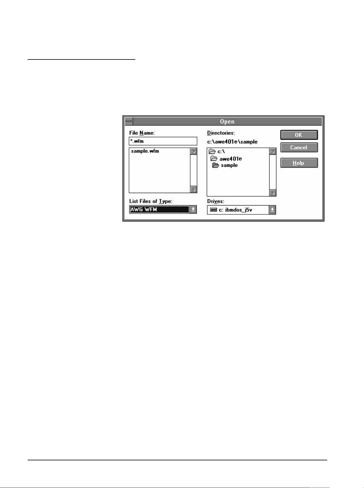
File Operations
Import
The Import menu selection can be used to retrieve a waveform from a file
written by another software system or instrument. You can import from a file
written in any of the formats TDS WFM, AWG WFM, TDS ASCII and IQSIM
ASCII. Waveforms in Files in general ASCII and binary formats can also be
imported.
Figure 3Ć7:ăThe Import Dialog Box
File Name Ċ Enter the name of the waveform to be loaded in the File
Name edit box or click on one of the names in the list box. To change direcĆ
tories or drives, use the Directories and/or Drives list boxes. You can choose
the kind of files listed in the File Name list box by selecting entries from the
List Files of Type list box or by specifying a particular file group with a wild
card" in the File Name edit box. For example, to list only files having a .BIN"
extension, enter *.BIN".
List Files of Type Ċ Lists the types of files from which WaveWriter can
import waveforms. The possible types with their customary extension are as
follows.
H TDS WFM (*.WFM) Ċ A format used by Tektronix TDS series
digital scopes.
H TDS ASCII (*.DAT) Ċ Another format used by Tektronix TDS series
digital scopes, but the contents of these files are written in ASCII
characters. Certain waveform parameters placed at the top of the
files are recognized by WaveWriter.
H AWG2000 WFM (*.WFM) Ċ The format used by Sony/Tektronix
AWG2000 series Arbitrary Waveform Generators. The format of
these files is different from that of TDS WFM files; only the customary
extension is the same.
3Ć14
Reference
Page 87

File Operations
H AWG500/600 WFM (*.WFM) Ċ The format used by Sony/Tektronix
AWG500/600 series Arbitrary Waveform Generators. The format of
these files is different from that of AWG2000 WFM files; only the
customary extension is the same.
H AWG500/600 PAT (*.PAT) Ċ The format used by Sony/Tektronix
AWG500/600 series Arbitrary Waveform Generators. The format of
these files is used for pattern data file.
H IQSIM ASCII (*.I, *.Q) Ċ A format written in ASCII characters
produced by signal processing applications such as IQSIM by R&S.
H BINARY (*.BIN) Ċ These files can have a variety of formats which
are only similar in that the waveform data they contain is in a binary
format. When this format is selected and OK is clicked, the user will
be prompted for additional parameters to define the exact format.
(See the Binary Import Option dialog box in Figure 3Ć8.)
H ASCII (*.ASC) Ċ These files can have a variety of formats which
are only similar in that the waveform data they contain is written in
ASCII characters. When this format is selected and OK is clicked,
the user will be prompted for additional parameters to define the
exact format. (See the ASCII Import Option dialog box in Figure 3Ć9.)
Directories Ċ Lists the resident hierarchical directory structure including
parallel directories. (Used in conjunction with the Drives list box below.) Use
the Directories list box to find directory that contains the file you want to read
in. To switch directories, doubleĆclick on the folder for the desired directory.
To move to the root of a drive, doubleĆclick on the folder next to the drive
name. The associated list boxes will update to reflect the new directory
structure.
Drives Ċ Use the Drives list box to switch drives. Scroll and select the drive
you wish to use. The associated list boxes will update to reflect the new
directory structure.
OK Ċ Loads the selected waveform file as the current waveform or updates
the list box if the entry was a wild card. If you specified a nonexistent file in
the File Name edit box, a warning is issued and you are returned to the edit
box. If the specified file name is the same as a file name already in WaveWritĆ
er memory, you are given the option of replacing the file in memory or
creating a file with a different name.
For TDS WFM, TDS ASCII, AWG WFM and IQSIM ASCII, directly after you
select OK WaveWriter does some file format checking, and the Associate
Waveform with Instrument dialog appears. Refer to Figure 3Ć5 for the details
of this dialog. For BINARY and ASCII files another dialog will appear promptĆ
ing the user for details of the format of the file to be read.
WaveWriter (AWE) User Manual
Cancel Ċ Select Cancel to abort the current operation and return to the
main menu.
3Ć15
Page 88

File Operations
Figure 3Ć8:ăBinary Import Option Dialog Box
Binary Import Option Dialog Box
This dialog is used to define how a binary waveform file is read into WaveWĆ
riter. Such files can take a wide variety of formats in which waveform points
are represented by binary data. By setting the parameters of the read apĆ
propriately, WaveWriter can be made to extract just the waveform data part
of a file, ignoring data that is of no interest or is of unknown format.
The following parameters are available to handle various data formats.
Clock Frequency Ċ The default clock rate is initially displayed. You can
edit it to set the desired clock frequency.
Data Size Ċ This specifies the size of each point; 8, 12 or 16 bits may be
selected (for files containing integer point values), or Float (for files containĆ
ing floating point values). When Float is selected each point value is read in
32Ćbit floating point format.
Offset Binary Ċ Only applicable to integer formats. When this box is
checked, the point value data is assumed to be positive (offset) binary.
Otherwise, the data is assumed to be signed integer.
3Ć16
Skip Bytes Ċ What data you want to be read in is specified by choosing
either of the following methods.
Reference
Page 89

File Operations
H Find Data Block Ċ When this box is checked, the input file is
assumed to contain an arbitrary data block with a block header of
the form #41024... (for example) which specifies the length of the
data block. The preceding part of the file is ignored, and the data
block is located automatically. GPIB commands often use this
method for representing waveform data in a binary format, so this
option can be used for reading files containing GPIB commands.
H Leading, Trailing Ċ Instead of automatically finding the data, you
can specify a number of bytes starting at the top of the input file
which will be ignored. You can also specify a number of bytes to be
ignored at the end of the input file. The number of data points is
determined from the leading and trailing values, and the length of
the file.
Byte Order Ċ You can specify either LSB or MSB byte ordering for the
point values. LSB has the least significant byte first, as produced by Intel
x86 processors. MSB has the most significant byte first, as produced by
Motorola 680x0 processors.
OK Ċ Proceed to the Associate Waveform with Instrument dialog, and after
that, read in the waveform data.
Cancel - Cancel the Import command.
WaveWriter (AWE) User Manual
Figure 3Ć9:ăASCII Import Option Dialog Box
3Ć17
Page 90

File Operations
ASCII Import Option Dialog Box
This dialog is used to define how an ASCII waveform file is read into WaveWĆ
riter. In the file point data is written as floating point numbers. Fractional
parts and exponents may be omitted when they are not needed to express
the value (e.g. 12.3, -4.56e-3 and 7 will all be accepted).
Spaces , TABs, commas and newlines may be used to separate data items.
Using all of these separators in the same file is permitted. A group of separaĆ
tors is equivalent to a single separator.
The following parameters are available to handle various file formats.
Data Format - The sort of data that each point is assumed to be repreĆ
sented by can be selected. When Volt is selected, data is read assuming
each point is represented by a single voltage value. When Time Volt is
selected, data is read assuming each point is represented by a time folĆ
lowed by a voltage. When Number Volt is selected, a point number followed
by a voltage is assumed.
Clock Frequency - The default clock rate is initially displayed. You can
edit it to show the desired clock frequency. If the "Time Volt" data format is
selected, the clock rate is derived from the time values in the file, and the
Clock Frequency edit box is grayed.
Leading Skip - These parameters are useful for ignoring unwanted file
header information.
H Lines - The number of lines to be ignored from the top of the input
file.
H Items - The number of data items (tokens) to be ignored after the
above number of lines have been skipped.
OK - Proceed to the Associate Waveform with Instrument dialog, and after
that, read in the waveform data.
Cancel - Cancel the Import command.
Data Nonconformance
If the parameters of the waveform you are attempting to load do not match
those of the target instrument, several things may occur.
Vertical Ċ If the waveform amplitude exceeds the current axis range, the
display will be clipped. Use the Display ³ Autoscale Current Waveform
menu to rescale the display; no data is lost. If the waveform amplitude
exceeds the maximum range of the target instrument, Autoscale Current
3Ć18
Reference
Page 91

File Operations
Waveform sets the vertical axis range to the maximum instrument range.
That portion of the waveform beyond the instrument range will be shown
clipped.
Horizontal Ċ If the time per point of the incoming waveform does not
match the system clock rate, WaveWriter warns you of the mismatch.
Choose one of the following actions:
H Change the clock rate of the incoming waveform to the system clock
rate.
H Massage (expand or compress) the incoming waveform to maintain a
timing match. (See Horizontal Resolution, Page 3Ć26).
H Change the clock rate to match that of the incoming waveform. If the
incoming clock rate is not valid for the selected target instrument, the
option is grayed and unavailable.
H Cancel the Import command.
Export
The Export command stores the current waveform to a disk file in a format
that is compatible with other application programs or instruments. The file
format, directory path, and resident drive must be specified.
Figure 3Ć10:ăThe Export Dialog Box
WaveWriter (AWE) User Manual
File Name Ċ Enter the new or existing name for the waveform to be exĆ
ported. The eightĆcharacter file name and threeĆcharacter extension can be
any combination of characters acceptable to the DOS system. If no extenĆ
sion is given, a default extension identifying the file format type will be autoĆ
matically appended. If an extension is included, it will be used instead of the
3Ć19
Page 92

File Operations
default extension without verification of the selected Save File as Type (file
format). To set the write path of the file to be exported, modify the DirectoĆ
ries and or Drives list boxes.
Save File of Type Ċ Lists the types of files to which WaveWriter can
export waveforms. The possible types which the user can select with their
customary extensions are as follows.
H AWG2000 WFM (*.WFM) Ċ The native format used by Sony/TektroĆ
nix AWG2000 series Arbitrary Waveform Generators.
H AWG500/600 WFM (*.WFM) Ċ The native waveform file format
used by Sony/Tektronix AWG500 series and AWG610 Arbitrary
Waveform Generators.
H AWG500/600 PAT (*.PAT) Ċ The native pattern file format used by
Sony/Tektronix AWG500 series and AWG610 Arbitrary Waveform
Generators.
H ASCII (Volts) (*.ASC) Ċ Each point is represented by a voltage
written in ASCII characters.
H ASCII (Time Volts) (*.ASC) Ċ Each point is represented by a time
and a voltage written in ASCII characters.
H ASCII (Number Volts) (*.PRN) Ċ Each point is represented by a
point number and a voltage written in ASCII characters.
Refer to Appendix B for details of file formats.
Directories Ċ Lists the resident hierarchical directory structure including
parallel directories. (Used in conjunction with the Drives list box below.) Use
the Directories list box to find directory that contains the file you want to read
in. To switch directories, doubleĆclick on the folder for the desired directory.
To move to the root of a drive, doubleĆclick on the folder next to the drive
name. The associated list boxes will update to reflect the new directory
structure.
Drives Ċ Use the Drives list box to switch drives. Scroll and select the drive
you wish to use. The associated list boxes will update to reflect the new
directory structure.
OK Ċ Stores the current waveform file to the specified location using the
selected file format. If the specified file name already exists, you are
prompted requesting if you want to overwrite the existing file.
3Ć20
Cancel Ċ Select Cancel to abort the current operation and return to the
main menu.
Reference
Page 93
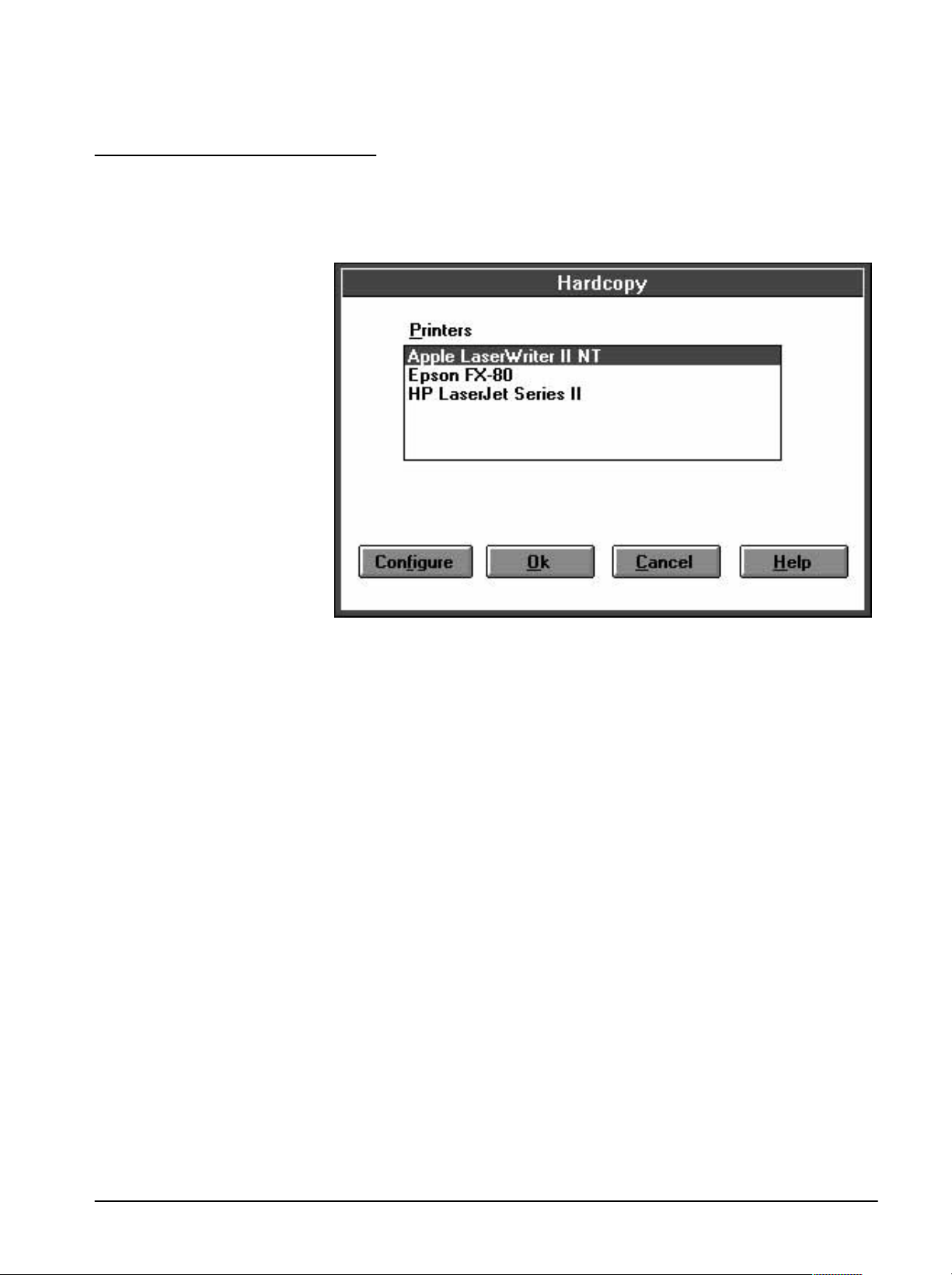
File Operations
Hardcopy
The Hardcopy command sends the current Waveform Display Area to the
selected printer or plotter. Selecting Hardcopy from the File menu displays
the dialog box in Figure 3Ć11.
Figure 3Ć11:ăHardcopy Dialog Box
Printers Ċ Lists the installed output device drivers; select an output device
from the list. To install additional printers, see the Windows User Guide.
Configure Ċ Displays the Windows Control Panel. The panel contains a
setup menu for printer selection and configuration. See your Microsoft
Windows Users manual for more detailed information.
OK Ċ Sends the current Waveform Display Area to the selected printer or
plotter. During data transfer, a Cancel Print dialog box appears allowing
termination of the print or plot prior to completion.
Cancel Ċ Select Cancel to abort the current operation and return to the
main menu.
Help Ċ Select Help to display information relating to this menu selection.
Use the scroll bar, if present, to read the entire Help text. To return to the
Hardcopy dialog box, select the ControlĆmenu box, then select Close.
WaveWriter (AWE) User Manual
3Ć21
Page 94

File Operations
Exit
About
The Exit selection ends the WaveWriter session and returns you to the
Windows Program Manager. If any data has been altered, you are prompted
to save it before exiting. The current WaveWriter configuration is saved.
Selecting About displays the dialog in Figure 3Ć12. The Dialog box lists:
H The program name, WaveWriter
H The version number
H Tektronix copyright
H Available memory
OK Ċ Selecting OK returns you to the main menu.
3Ć22
Figure 3Ć12:ăAbout Dialog Box
Reference
Page 95

Editing Waveforms
Many waveform modifications are possible without the Draw menu. Use the
following Edit Menu selections to modify the Current Waveform without
redrawing the waveform:
H Undo Ċ Cancels the most recent change to the current waveform made
by any menus.
H Disable Undo Ċ Disables and enables the Undo feature.
H Cut Between Markers Ċ Removes a portion of the current waveform;
saves the segment in the edit buffer.
H Copy Between Markers Ċ Copies a portion of the current waveform;
saves the segment in the edit buffer.
H Delete Between Markers Ċ Deletes a portion of the current waveform;
does not save the segment.
H Insert at Start Marker Ċ Inserts a copy of the edit buffer into the curĆ
rent waveform.
H Replace Between Markers Ċ Deletes a portion of the current waveform
and inserts a copy of the edit buffer into its place.
Undo
H Append to End of Waveform Ċ Appends a copy of the edit buffer to
the end of the current waveform.
H Flip Horizontal Between Markers Ċ Reverses the current waveform
time sequence.
H Flip Vertical Between Markers Ċ Inverts the current waveform with
instrument offset as the center.
H Horizontal Resolution Ċ Expands or compresses the current waveform
horizontally.
H Vertical Resolution Ċ Modifies waveform data to simulate a lower
vertical resolution.
The Undo selection cancels the most recent change to the current waveform.
If no modification has been made to the current waveform since it last be-
came the current waveform, or since it was created, this selection is disabled.
It can also be explicitly disabled with the Disable Undo selection.
WaveWriter (AWE) User Manual
3Ć23
Page 96

Editing Waveforms
Disable Undo
Cut Between Markers
Toggles the Undo feature between the disabled and enabled state. When a
check mark appears to the left of the Disable Undo selection, Undo is
disabled. Undo is a very useful feature, and the user is recommended to
leave it in the enabled state most of the time. However, when very big waveforms are being edited, Undo may take an unacceptable amount of time and
disk space. Selecting this menu item will avoid these problems.
Removes that portion of the current waveform between and including the
Start and Stop markers and stores the information in the edit buffer. The Stop
Marker and the data to its right is shifted to the left to align with the Start
Marker position. Information stored in the buffer can be pasted to another
waveform.
The Edit Buffer
Information stored in the edit buffer can be pasted into other waveforms
using the Insert at Start Marker, Replace Between Markers, or Append to End
of Waveform commands. First, select a new current waveform from the
Waveforms menu, then implement one of the commands as described
below. Edit buffer data is available for multiple insert, replace, and append
operations but is replaced when another cut or copy command is selected.
Copy Between
Markers
Delete Between
Markers
Insert at Start Marker
Copies that portion of the current waveform between and including the Start
and Stop markers to the edit buffer. The current waveform does not change.
Removes that portion of the current waveform between and including the
Start and Stop markers. The Stop Marker, and the data to its right, shifts left
to align with the Start Marker position. The deleted waveform segment is not
saved in the edit buffer.
Inserts a copy of the waveform data from the edit buffer into the current
waveform at the Start Marker location. Waveform data at the Start Marker and
to the right is moved to align with the end of the inserted data. (This may
extend the current waveform beyond its originally defined length.)
The distance between the markers cannot exceed the maximum record
length of the target instrument. If insertion of data from the edit buffer
causes the Stop Marker to go beyond this limit, the Stop Marker moves only
to the maximum length allowed.
3Ć24
Reference
Page 97

Editing Waveforms
Replace Between
Markers
Append to End of
Waveform
Flip Horizontal
Between Markers
A copy of the waveform data stored in the edit buffer replaces the current
waveform between and including the Start and Stop markers. If the edit
buffer data is longer than the segment being replaced, the current waveform
extends beyond its originally defined length. If the edit buffer data is shorter
than the segment being replaced, the current waveform is shortened.
The distance between markers cannot exceed the maximum record length
of the target instrument. If insertion of data from the edit buffer causes the
Stop Marker to go beyond this limit, the Stop Marker moves only to the
maximum length allowed.
Appends a copy of the waveform data stored in the edit buffer to the end of
the current waveform following the last data point. This extends the current
waveform beyond its originally defined length.
Reverses the timing of the current waveform between and including the Start
and Stop markers. What was the the begging of the waveform segment is
now the end, and conversely.
Flip Vertical Between
Markers
Inverts the polarity of the current waveform (between and including the Start
and Stop markers) around the current external offset.
WaveWriter (AWE) User Manual
3Ć25
Page 98

Editing Waveforms
Horizontal Resolution
A defined portion of the current waveform can be expanded or compressed
along the horizontal axis. Select Horizontal Resolution from the Edit menu to
specify the processing region; the dialog box shown in Figure 3Ć13 appears.
3Ć26
Figure 3Ć13:ăHorizontal Resolution Dialog Box
Processing Region Ċ Define the length of the waveform affected by the
horizontal resolution change:
H When Entire Wfm is selected, the Waveform Interval: Stop - Start line
notes the total length of the waveform in points and seconds.
H When Between Markers is selected, the Interval Between Markers: Stop
- Start line notes the length of the segment between and including the
markers in points and seconds.
New Interval Ċ Specify the desired length, either the entire waveform or
the marked segment. Select either Points or Seconds.
Reference
Page 99

Editing Waveforms
Transform Method Ċ There are three transform methods for redefining
the horizontal interval: Nearest Related Point, Short Function, and Longer
Function. Figure 3Ć14 depicts a sine wave transformed by each of these
methods.
A: Nearest Related Point B: Short Function C: Longer Function
Figure 3Ć14:ăThree Results of a Sine Wave Transformation
Nearest Related Point Ċ The fastest method of redefining the horizontal
interval. Each newly assigned point is given the closest horizontal value to
the original point. This method preserves steps in the original waveform.
Short Function Ċ The generalĆpurpose method of redefining the horizonĆ
tal interval. Each new point is calculated using a weighted average of the
original points to either side. The weighting function shape is triangular,
linearly decreasing as you move away from the new point location. When a
waveform interval is increased (more points), the Short Function translates
to linear interpolation; the new point is located on a straight line between the
two original points. When the new interval is decreased or decimated (fewer
points), the triangular weighted average spans four or more original points
to calculate each new point. Greater decimation ratios require wider averagĆ
ing functions.
Longer Function Ċ The slowest and most accurate method of redefining
the horizontal interval. This method produces smooth bandĆlimited signals
(sine waves). Like the Short Function, this method calculates each new point
with a weighted average of original points to either side. This weighting
function is up to five times as wide as the triangular Short Function. When
increasing intervals (interpolating), the weighted average spans ten points,
five on each side. When decreasing intervals (decimating), the point span of
the average is ten times the ratio of original to new interval lengths. The
weighting function shape sinc function (sin(x)/x)
limit its length. Sine waves with at least four points per cycle can be accuĆ
a
has been windowedbto
WaveWriter (AWE) User Manual
3Ć27
Page 100

Editing Waveforms
rately interpolated using the Longer Function (as shown in Figure 3Ć14C)
with errors of less than 0.1%. Similarly, reducing a sine wave interval down
to as few as four samples per cycle results in errors less than 0.1%.
a
The sinc is the ideal interpolation function for sampled bandĆlimited (nonaliased) signals.
b
The 3Ćterm (-67 dB) BlackmanĆHarriscwindow spanning the fifth zero crossing on either
side of the main sinc lobe.
c
Harris, F.J., On the Use of Windows for Harmonic Analysis with the Discrete Fourier TransĆ
form, Proceeding of the IEEE, Vol. 66, No. 1, Jan 1978.
Use Data Beyond Markers for New Data Calculation Ċ When impleĆ
menting the Longer Function (or Short Function when compressing a waveĆ
form) to minimize distortion at the end points of the waveform, the
transformation calculation requires data points outside the limits of the Start
and Stop markers. Select the Yes option button to acquire the data points. If
the markers are at the ends of the waveform, extrapolated data points are
calculated. If you do not wish to use external data points, select the No
option button. This group box is grayed (not available for selection) when
Nearest Related Point is selected.
OK Ċ When OK is selected, the processing region is resized to the new
length. The overall current waveform will lengthen or shorten accordingly.
Cancel Ċ Select Cancel to abort the current operation and return to the
main menu.
Help Ċ Select Help to display information relating to this menu selection.
Use the scroll bar, if present, to read the entire Help text. To return to the
previous dialog box, select the ControlĆmenu box, then select Close.
NOTE
Altering the Horizontal resolution does not change the clock rate.
3Ć28
Reference
 Loading...