

Page 1

User Manual
VX4790A
Arbitrary Waveform Generator Module
070-9152-02
This document applies for firmware version 1.00
and above.
Warning
The servicing instructions are for use by qualified
personnel only. To avoid personal injury, do not
perform any servicing unless you are qualified to
do so. Refer to the Safety Summary prior to
performing service.
Page 2

Copyright E T ektronix, Inc. 1992, 1994. All rights reserved.
T ektronix products are covered by U.S. and foreign patents, issued and pending. Information in this publication supercedes
that in all previously published material. Specifications and price change privileges reserved.
Printed in the U.S.A.
T ektronix, Inc., P.O. Box 1000, Wilsonville, OR 97070–1000
TEKTRONIX and TEK are registered trademarks of T ektronix, Inc.
Page 3

WARRANTY
T ektronix warrants that this product will be free from defects in materials and workmanship for a period of three
(3) years from the date of shipment. If any such product proves defective during this warranty period, T ektronix,
at its option, either will repair the defective product without charge for parts and labor, or will provide a
replacement in exchange for the defective product.
In order to obtain service under this warranty, Customer must notify Tektronix of the defect before the expiration
of the warranty period and make suitable arrangements for the performance of service. Customer shall be
responsible for packaging and shipping the defective product to the service center designated by T ektronix, with
shipping charges prepaid. Tektronix shall pay for the return of the product to Customer if the shipment is to a
location within the country in which the T ektronix service center is located. Customer shall be responsible for
paying all shipping charges, duties, taxes, and any other charges for products returned to any other locations.
This warranty shall not apply to any defect, failure or damage caused by improper use or improper or inadequate
maintenance and care. T ektronix shall not be obligated to furnish service under this warranty a) to repair damage
resulting from attempts by personnel other than T ektronix representatives to install, repair or service the product;
b) to repair damage resulting from improper use or connection to incompatible equipment; or c) to service a
product that has been modified or integrated with other products when the effect of such modification or
integration increases the time or difficulty of servicing the product.
THIS WARRANTY IS GIVEN BY TEKTRONIX WITH RESPECT TO THIS PRODUCT IN LIEU OF
ANY OTHER WARRANTIES, EXPRESSED OR IMPLIED. TEKTRONIX AND ITS VENDORS
DISCLAIM ANY IMPLIED WARRANTIES OF MERCHANTABILITY OR FITNESS FOR A
P ARTICULAR PURPOSE. TEKTRONIX’ RESPONSIBILITY TO REP AIR OR REPLACE DEFECTIVE
PRODUCTS IS THE SOLE AND EXCLUSIVE REMEDY PROVIDED TO THE CUSTOMER FOR
BREACH OF THIS WARRANTY. TEKTRONIX AND ITS VENDORS WILL NOT BE LIABLE FOR ANY
INDIRECT, SPECIAL, INCIDENT AL, OR CONSEQUENTIAL DAMAGES IRRESPECTIVE OF
WHETHER TEKTRONIX OR THE VENDOR HAS ADVANCE NOTICE OF THE POSSIBILITY OF
SUCH DAMAGES.
Page 4

EC Declaration of Conformity
We
Tektronix Holland N.V.
Marktweg 73A
8444 AB Heerenveen
The Netherlands
declare under sole responsibility that the
VX4790A and all options
meets the intent of Directive 89/336/EEC for Electromagnetic Compatibility.
Compliance was demonstrated to the following specifications as listed in the Official
Journal of the European Communities:
EN 55011 Class A Radiated and Conducted Emissions
EN 50081-1 Emissions:
EN 60555-2 AC Power Line Harmonic Emissions
EN 50082-1 Immunity:
IEC 801-2 Electrostatic Discharge Immunity
IEC 801-3 RF Electromagnetic Field Immunity
IEC 801-4 Electrical Fast Transient/Burst Immunity
IEC 801-5 Power Line Surge Immunity
CONDITIONS: To ensure compliance with EMC requirements this module must be
installed in a mainframe which has backplane shields installed which comply with Rule
B.7.45 of the VXIbus Specification.
Page 5
Page 6
Page 7

Table of Contents
Section 1
General Information and Specifications
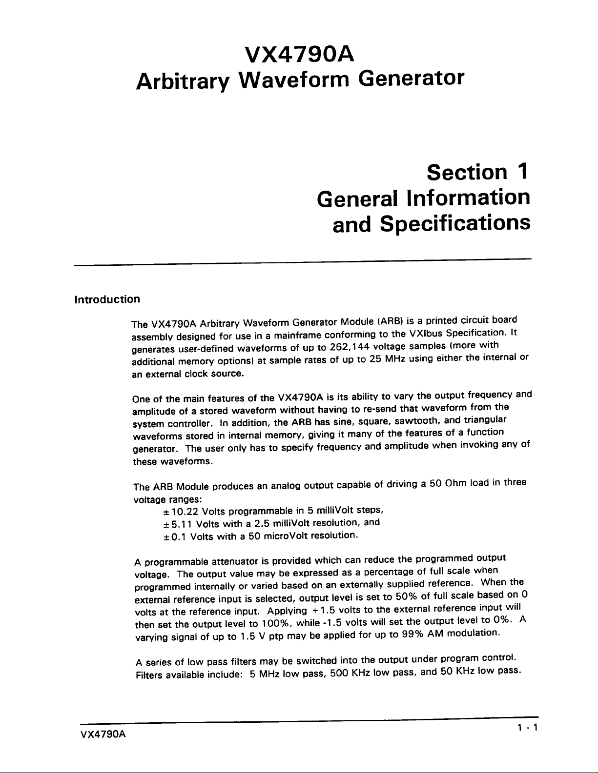
Introduction 1-1......................................................................
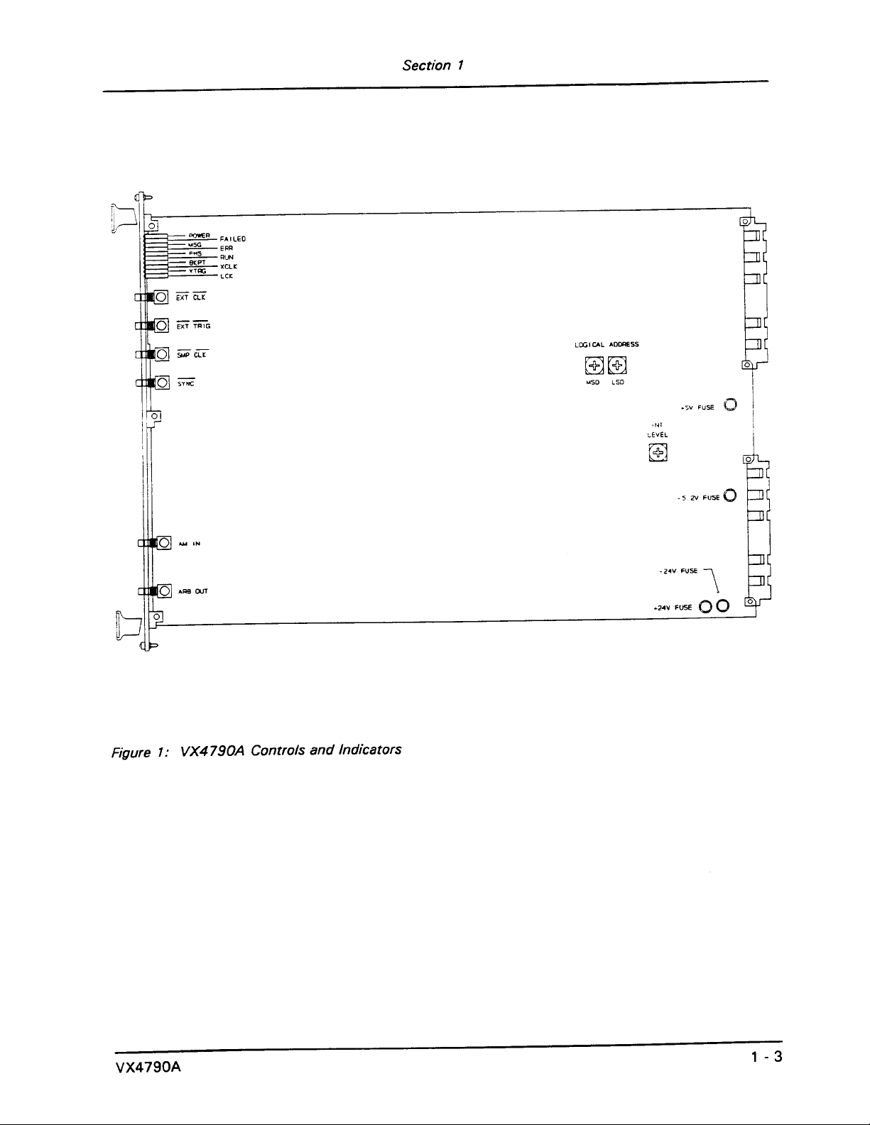
Controls And Indicators 1 - 4............................................................
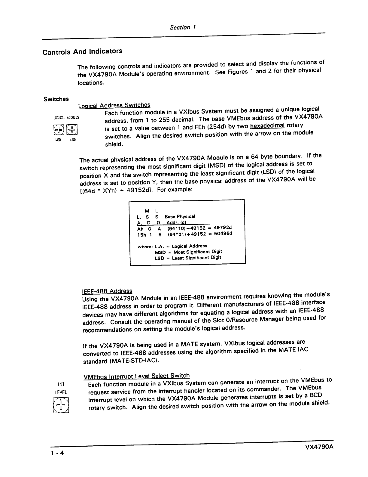
Switches 1-4....................................................................
Fuses 1-5.......................................................................
LEDs 1-5.......................................................................
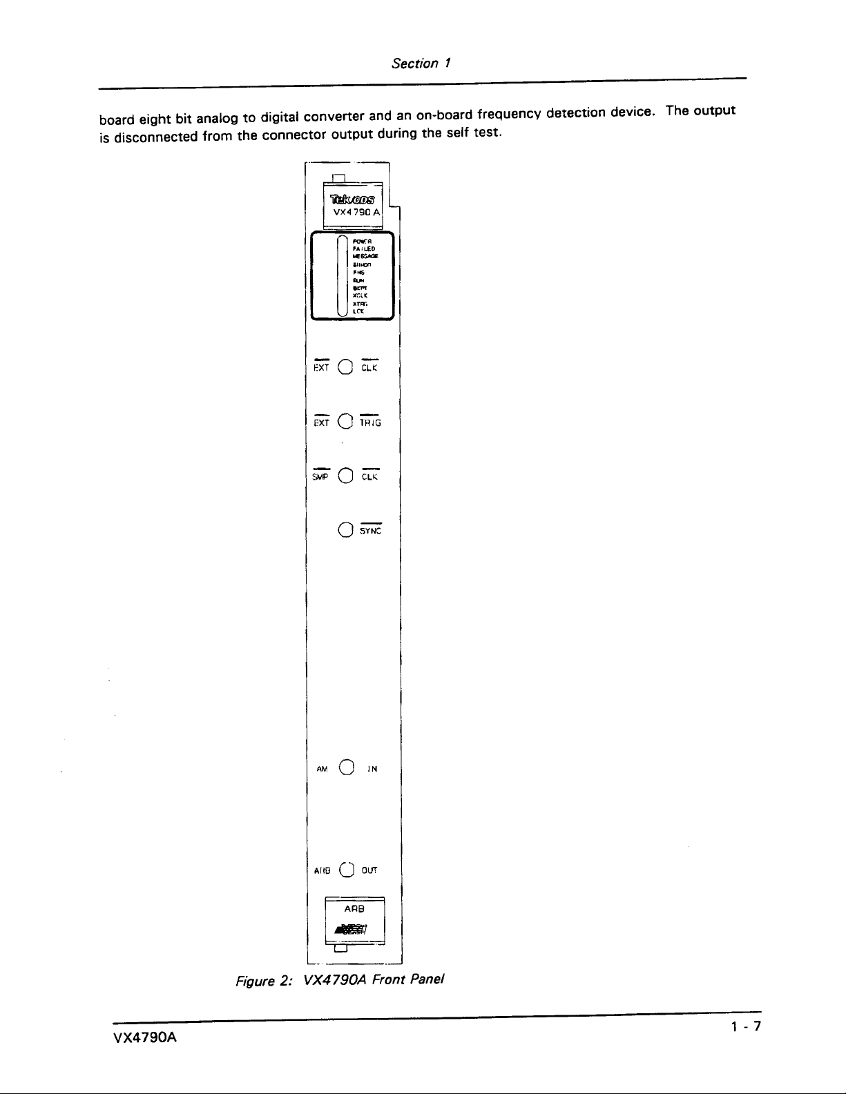
SMB Connector Inputs and Outputs 1 - 6............................................
BITE (BuiltĆIn Test Equipment) 1 - 6......................................................
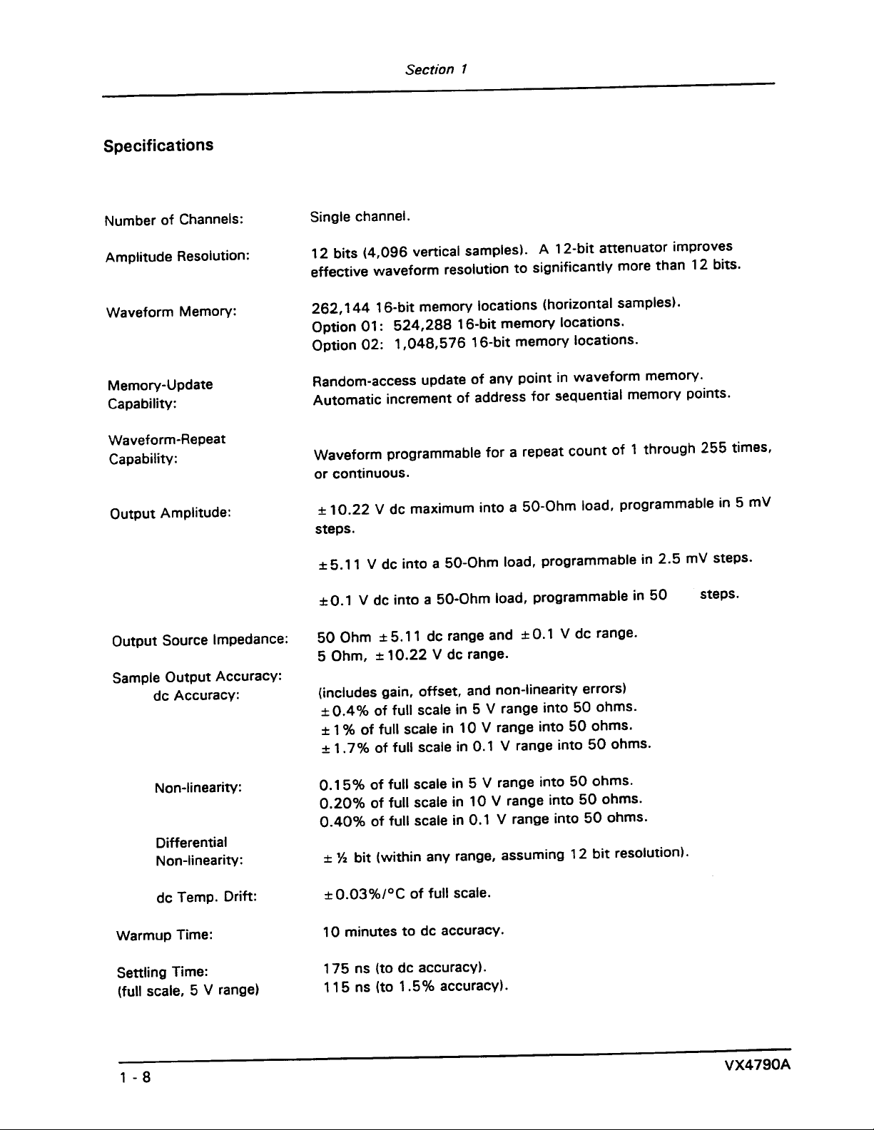
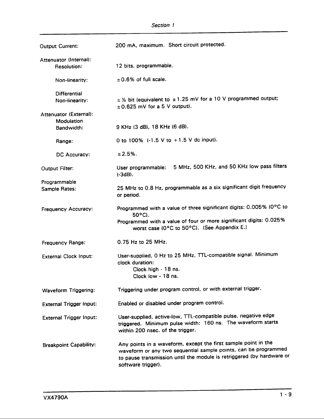
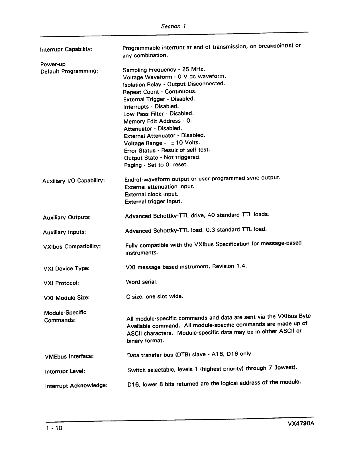
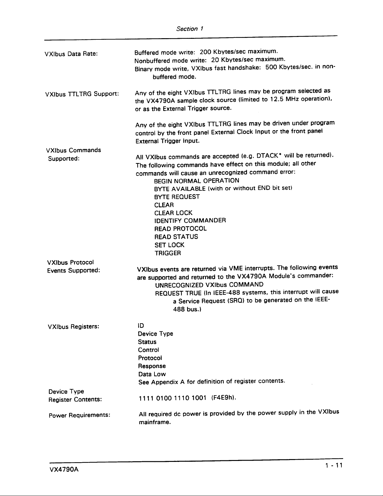
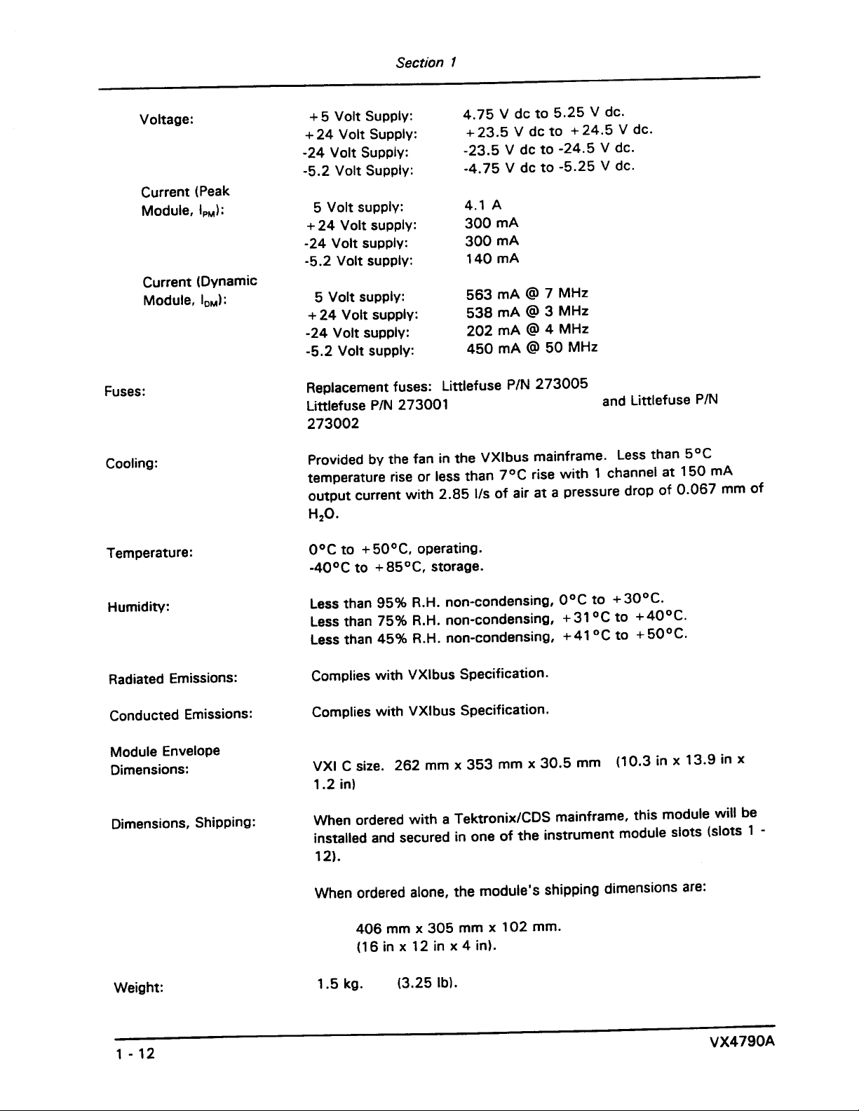
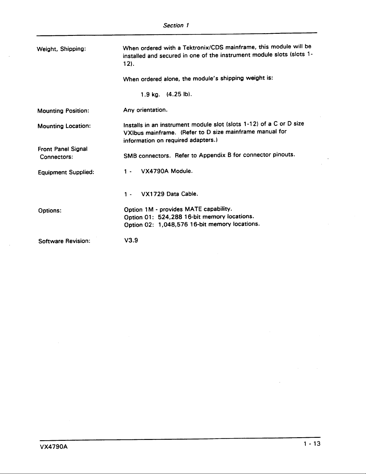
Specifications 1-8.....................................................................
Section 2
Preparation For Use
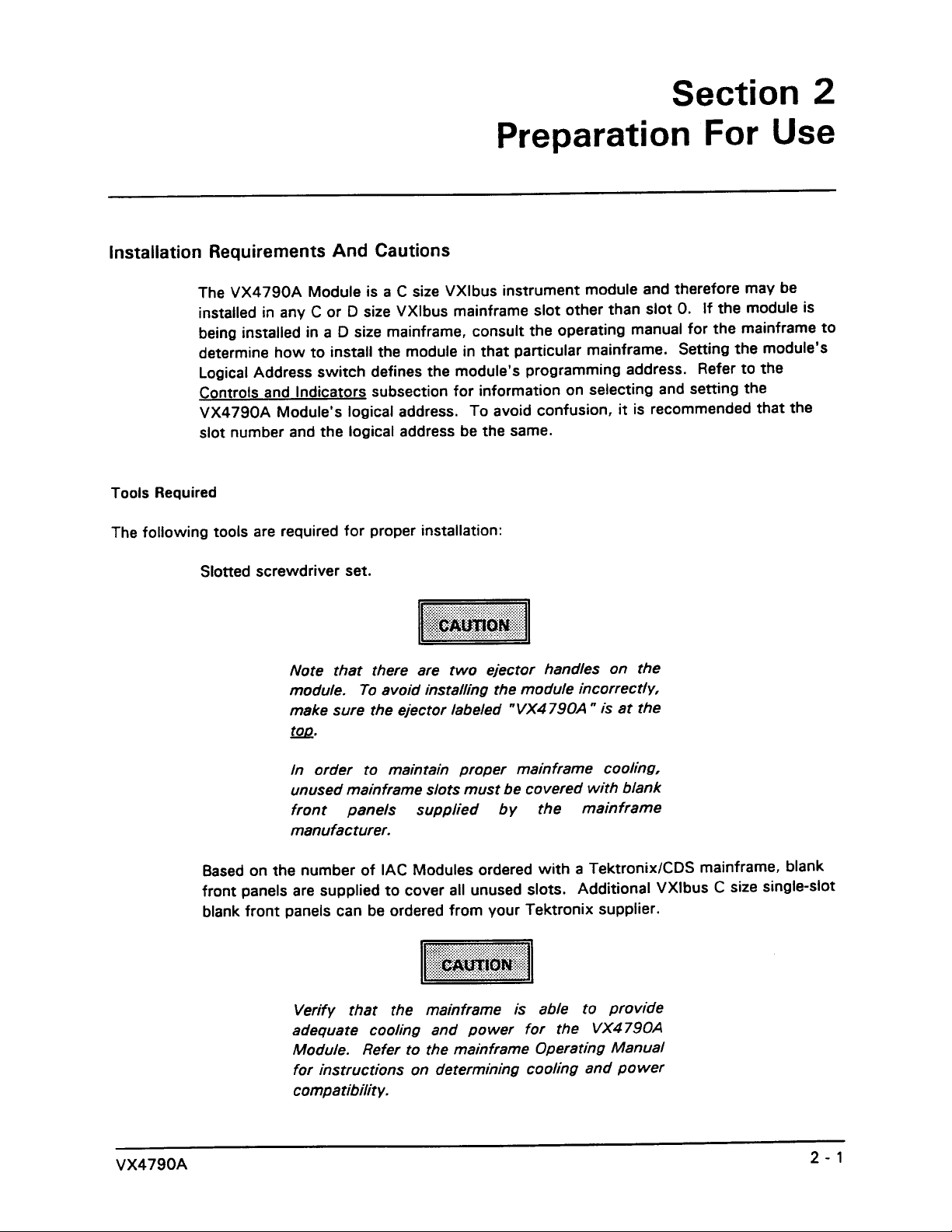
Installation Requirements And Cautions 2 - 1..............................................
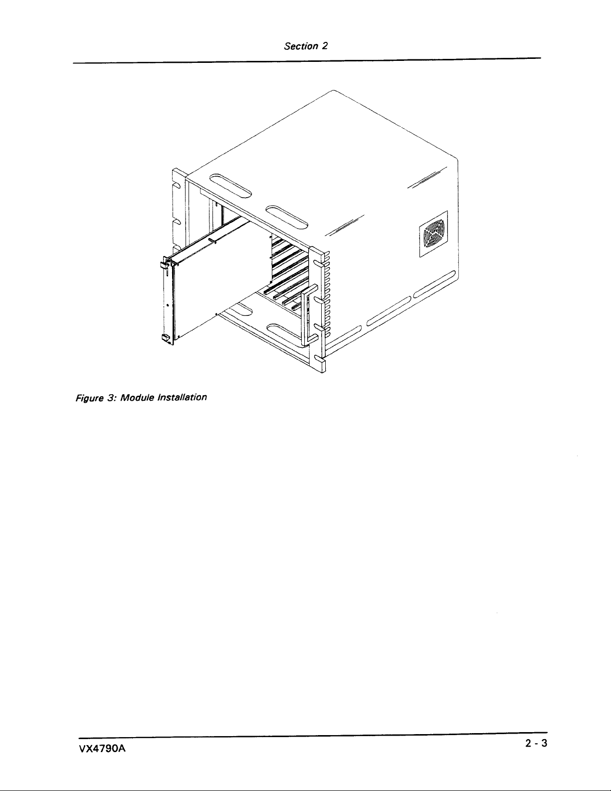
Installation Procedure 2 - 2..............................................................
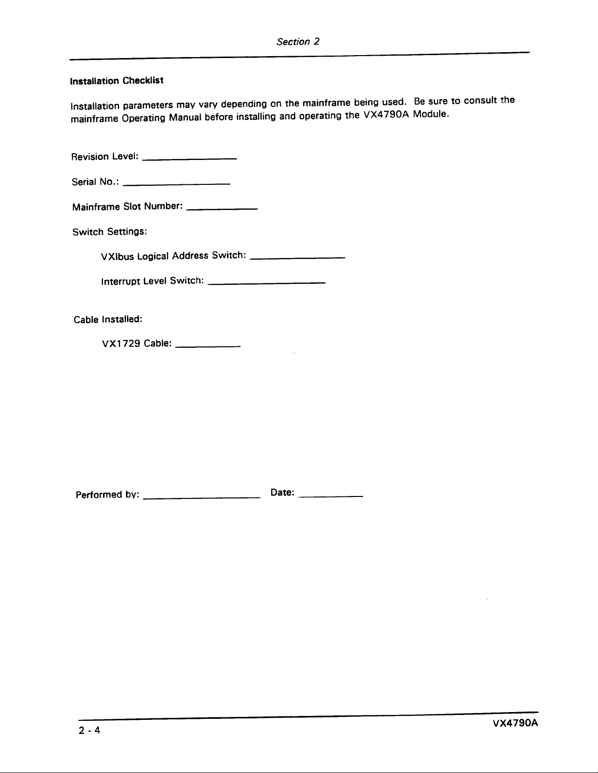
Installation Checklist 2-4...............................................................
Section 3
Operation
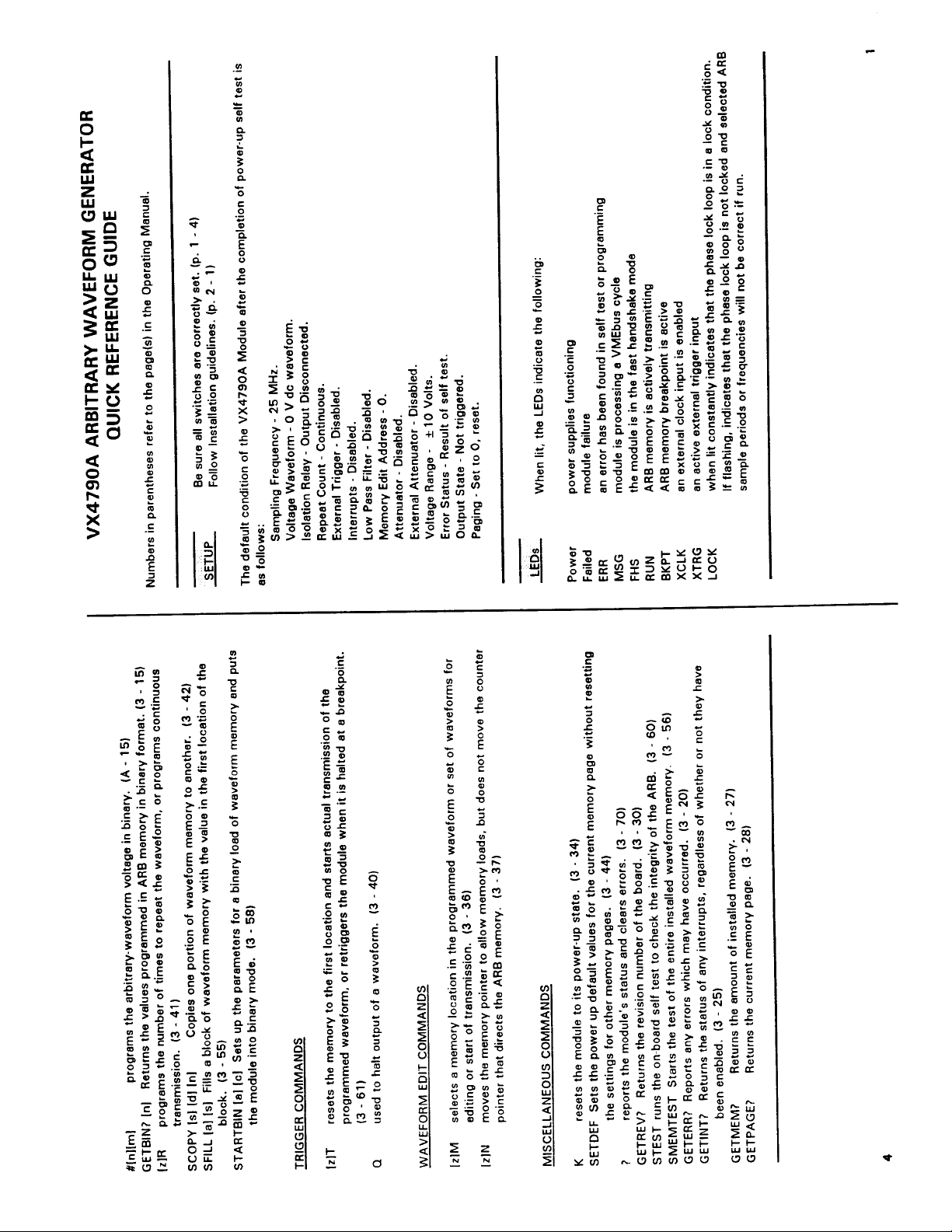
Overview 3-1.........................................................................
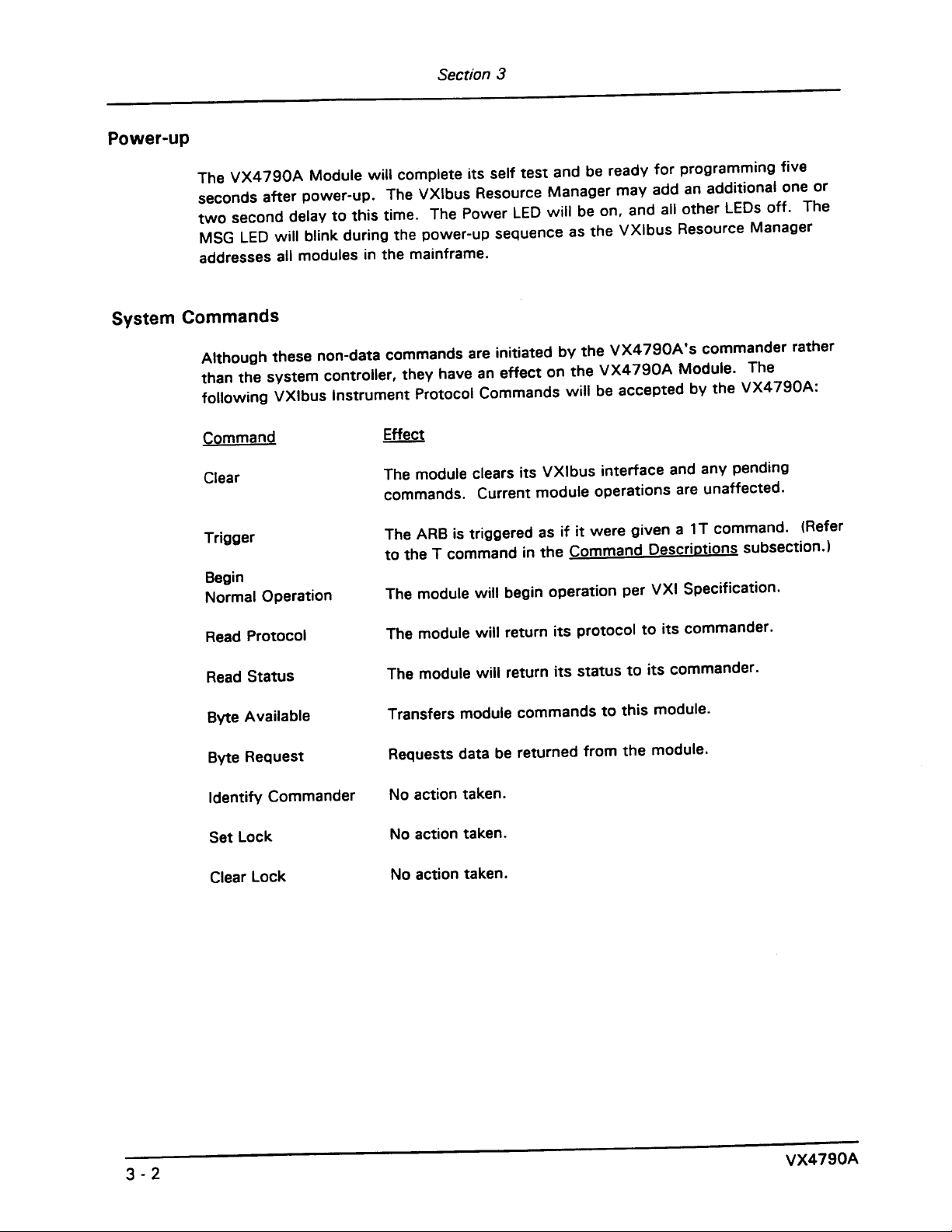
PowerĆup 3-2.........................................................................
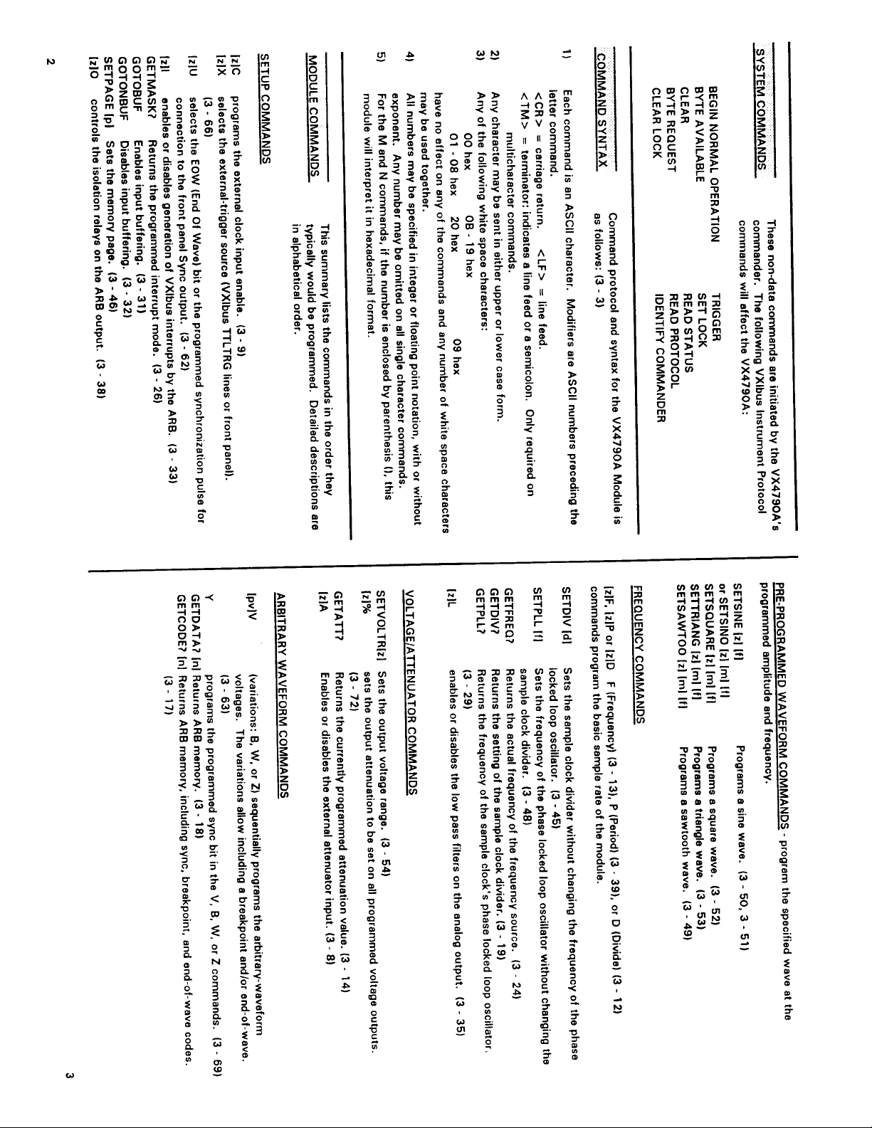
System Commands 3-2...............................................................
Module Commands 3-3...............................................................
Summary 3-4....................................................................
Command Descriptions 3 - 8.......................................................
SYSFAIL, Self Test, and Initialization 3 - 73................................................
Synchronizing Multiple Instrumentation Modules 3 - 74.....................................
Section 4
Programming Examples
Definition of BASIC Commands 4 - 1.....................................................
Programming Example In BASIC 4 - 2....................................................
Appendices
Appendix A - VXIbus Operation A - 1....................................................
Appendix B - Input/Output Connections A - 5.............................................
Appendix C - VXI Glossary A - 7........................................................
Appendix D - Advanced Program Capabilities A - 15.......................................
Appendix E - Frequency Source Accuracy A - 19..........................................
Appendix F (Option 1M) - MATE Programming A - 21......................................
Appendix G - User Service A - 41.......................................................
Appendix H - Options A - 43............................................................
Appendix I - VX4790A Performance Verification A - 45.....................................
Appendix J - VX4790A Adjustment Procedure A - 67.......................................
VX4790A
i
Page 8

Table of Contents
ii
VX4790A
Page 9

General Safety Summary
Review the following safety precautions to avoid injury and prevent damage to
this product or any products connected to it.
Only qualified personnel should perform service procedures.
While using this product, you may need to access other parts of the system. Read
the General Safety Summary in other system manuals for warnings and cautions
related to operating the system.
Injury Precautions
Avoid Electric Overload
Do Not Operate Without
Covers
Use Proper Fuse
Do Not Operate in
Wet/Damp Conditions
Do Not Operate in an
Explosive Atmosphere
To avoid electric shock or fire hazard, do not apply a voltage to a terminal that is
outside the range specified for that terminal.
To avoid electric shock or fire hazard, do not operate this product with covers or
panels removed.
To avoid fire hazard, use only the fuse type and rating specified for this product.
To avoid electric shock, do not operate this product in wet or damp conditions.
To avoid injury or fire hazard, do not operate this product in an explosive
atmosphere.
Product Damage Precautions
Provide Proper Ventilation
To prevent product overheating, provide proper ventilation.
Do Not Operate With
Suspected Failures
If you suspect there is damage to this product, have it inspected by qualified
service personnel.
Safety Terms and Symbols
Terms in This Manual
VX4790A Arbitrary Waveform Generator Module
These terms may appear in this manual:
iii
Page 10
General Safety Summary
WARNING. Warning statements identify conditions or practices that could result
in injury or loss of life.
CAUTION. Caution statements identify conditions or practices that could result in
damage to this product or other property.
Terms on the Product
These terms may appear on the product:
DANGER indicates an injury hazard immediately accessible as you read the
marking.
WARNING indicates an injury hazard not immediately accessible as you read the
marking.
CAUTION indicates a hazard to property including the product.
Symbols on the Product
The following symbols may appear on the product:
DANGER
High Voltage
Certifications and Compliances
Overvoltage Category
Overvoltage categories are defined as follows:
Protective Ground
(Earth) T erminal
ATTENTION
Refer to Manual
Double
Insulated
CAT III: Distribution level mains, fixed installation
CAT II: Local level mains, appliances, portable equipment
CAT I: Signal level, special equipment or parts of equipment, telecommunica-
tion, electronics
iv
VX4790A Arbitrary Waveform Generator Module
Page 11
Page 12
Page 13
Page 14
Page 15
Page 16

Page 17
Page 18
uV
Page 19
Page 20
Page 21
Page 22
Page 23
Page 24

Page 25
Page 26
Page 27
Page 28
Page 29
Page 30
Page 31

Page 32

Page 33

Page 34

Page 35

Page 36

Page 37

Page 38

Page 39

Page 40

Page 41

Page 42

Page 43

Page 44

Page 45

Page 46

Page 47

Page 48

Page 49

Page 50

Page 51

Page 52

Page 53

Page 54

Page 55

Page 56

Page 57

Page 58

Page 59

Page 60

Page 61

Page 62

Page 63

Page 64

Page 65

Page 66

Page 67

Page 68

Page 69

Page 70

Page 71

Page 72

Page 73

Page 74

Page 75

Page 76

Page 77

Page 78

Section 3
Command: SETHAVR
Syntax: SETHAVR [z] [f]<TM> or SHV [z] [f]<TM>
Purpose: This command loads ARB memory with a haversine function at the programmed
voltage and frequency.
Description: This command loads ARB memory with a haversine function. The haversine
2
function is equivalent to 1/2 (1 - cos Q)., which is also equivalent to sin
(1/2 Q).
The command has the following parameters:
[z] specifies the peak voltage level in volts. The haversine function will have
maximum value of [z] and minimum value of 0 volts.
[f] specifies the frequency in Hertz. Note that the function repeates every 180
degrees, which may make it appear that the function is operating at twice the
given frequency.
The frequency (F, D, P commands), voltage range (SETVOLTR command), and
attenuation (%, A commands) will all be reprogrammed by this command. The
voltage range will be set to the lowest voltage range possible, and the attenuation
will be reprogrammed and set for internal. The frequency and attenuation which
was actually programmed may be obtained with the GETFREQ? and GETATT?
commands respectively. Note that the GETFREQ? command returns the sample
frequency, not the frequency of the programmed wave.
The SETHAVR command is provided to give the ARB Module function generator
capability. However, since an ARB basically outputs a sequence of discrete
voltage levels, the quality of the haversine function signal will diminish as the
haversine function frequency approaches the maximum sample frequency of 25
MHz. Maximum frequency available will depend on the quality of the signal
required in the application. For haversine function waveforms, the availability of
the filtering provided by the L (Low Pass Filter) command maximizes the useful
frequency range of the SETHAVR command.
A trigger (T or External Trigger) command must be given to start the waveform.
Example: SETHAVR 3.12 350<CR><LF>
The ARB is programmed with a haversine function with maximum value of 3.12
volts, a minimum value of 0 volts, and a frequency of 350 Hz.
SHV 3.12 350<CR><LF>
This example would create the same result as the previous example.
3Ć50 VX4790A
Page 79

Page 80

Page 81

Page 82

Page 83

Page 84

Page 85

Page 86

Page 87

Page 88

Page 89

Page 90

Page 91

Page 92

Page 93

Page 94

Page 95

Page 96

Page 97

Page 98

Page 99

Page 100

 Loading...