

Page 1

Artisan Technology Group is your source for quality
new and certied-used/pre-owned equipment
• FAST SHIPPING AND
DELIVERY
• TENS OF THOUSANDS OF
IN-STOCK ITEMS
• EQUIPMENT DEMOS
• HUNDREDS OF
MANUFACTURERS
SUPPORTED
• LEASING/MONTHLY
RENTALS
• ITAR CERTIFIED
SECURE ASSET SOLUTIONS
SERVICE CENTER REPAIRS
Experienced engineers and technicians on staff
at our full-service, in-house repair center
Instra
Remotely inspect equipment before purchasing with
our interactive website at www.instraview.com
Contact us: (888) 88-SOURCE | sales@artisantg.com | www.artisantg.com
SM
REMOTE INSPECTION
View
WE BUY USED EQUIPMENT
Sell your excess, underutilized, and idle used equipment
We also offer credit for buy-backs and trade-ins
www.artisantg.com/WeBuyEquipment
LOOKING FOR MORE INFORMATION?
Visit us on the web at www.artisantg.com for more
information on price quotations, drivers, technical
specications, manuals, and documentation
Page 2

This manual was downloaded from Artisan Scientific Corporation.
If you are interested in other electrical T&M, optical T&M, and/or laboratory
equipment please visit us on the web at http://www.artisan-scientific.com
.
Artisan Technology Group - Quality Instrumentation ... Guaranteed | (888) 88-SOURCE | www.artisantg.com
Page 3
User Manual
Tektronix
/
VX4521
Advanced
Resource
Manager
This
document applies
for
firmware version
1.00
and
above.
Please
check
for
change
information
at the
rear
of
this
manual.
Second Edition:
September
1994
Artisan Technology Group - Quality Instrumentation ... Guaranteed | (888) 88-SOURCE | www.artisantg.com
Page 4
Copyright O Tektronix, Inc.
1992,
1994.
All
rights
reserved.
Tektronix products are covered
by
U.S.
and foreign patents, issued and pending. Information
in
this publication supercedes
that
in
all
previously published
material.
Specifications and
price
change privileges reserved.
Printed
in
the
U.S.A.
Tektronix, Inc.,
P.O.
Box 1000, Wilsonville,
OR
97070-1000
TEKTRONIX
and
TEK
are registered trademarks of Tektronix, Inc.
Artisan Technology Group - Quality Instrumentation ... Guaranteed | (888) 88-SOURCE | www.artisantg.com
Page 5
WARRANTY
TekUonix w'mants that this product will be free from detccts in materials and workmanship for a period of three
(3)
years from the date of shipment. If any such product proves defective during this warranty period, Tektronix,
at its option, either will repair the defective product without charge for parts and labor, or will provide a
replacement
in exchange for thc defective product.
In order to obtain service under this warranty, Customer must notify Tektronix of the defect before the expiration
of the warranty period and make suitable arrangements for the performance of service. Customer shall be
responsible for packaging and shipping the defective product to the service center designated by Tektronix, with
shipping charges prepaid. Tektronix shall pay for the return of the product to Customer if the shipment is to a
location within the
counlry in which the Tektronix service center is located. Customer shall be responsible for
paying
all
shipping charges, duties, taxes, and my other charges for products returned to any other locations.
This warranty shall not apply to
any
defect, failure or damage caused by improper use or improper or inadequate
maintennnce and care. l'ektronix shall not be obligated to furnish service under this warranty a) to repair damage
resulting from attempts by personnel other than Tektronix representatives to install, repair or service the product;
b)
to repair damage resulting from improper use or connection to incompatible equipment; or c) to service a
product that has been modified or integrated with other products when the effect of such modification or
integration increases the time or difficulty of servicing the product.
THIS WARRANTY IS GIVEN BY TEKTRONIX WITH RESPECT TO THIS PRODUCT IN LIEU OF
ANY OTHER WARRANTIES, EXPRESSED OR IMPLIED. TEKTRONIX AND ITS VENDORS
DISCLAIM ANY IMPLLED WARRANTIES OF MERCHANTABILITY OR FITNESS FOR A
-
PARTICU1,AR PURPOSE. TEKTKONIX' RESPONSIBILITY TO REPAIR OR REI'LACE DEFECTIVE
PRODUCTS IS
THE
SOLE AND EXCLUSIVE REMEDY PROVIDED TO THE CUSTOMER FOR
BREACH OF THIS WARRANTY. TEKTRONIX AND ITS VENDORS WILL NOT BE LIABLE FOR ANY
INDIRECT, SPECIAL, INCIDENTAL, OR
CONSEQUENTIAI, DAMAGES IRRESPECTIVE OF
WHETHER TEKTRONIX OR
THE
VENDOR HAS ADVANCE NOTICE OF THE POSSIHI1,ITY OF
SUCH DAMAGES.
Artisan Technology Group - Quality Instrumentation ... Guaranteed | (888) 88-SOURCE | www.artisantg.com
Page 6
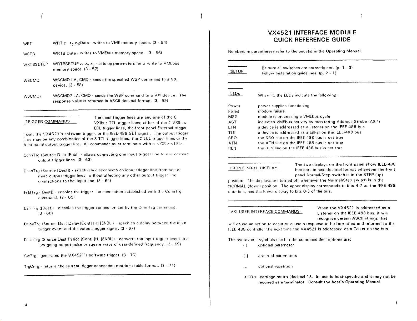
WRT
WRTB
WRTBSETUP
WSCMD
WSCMD?
WRT
7,
z2
z,;Data - writes to VME memory space. (3 - 541
WRTB Data
-
writes to VMEbus memory space. (3 - 56)
WRTBSETUP
z,
7,
z3
-
sets up parameters for a write to VMEbus
memory space. (3
-
57)
WSCMD LA, CMD - sends the specified WSP conirnand to a VXI
device. (3
-
581
WSCMD? LA, CMD
-
sends the WSP command to a VXI tlevlce. The
response value is returned in ASCII decimal format. (3
-
59)
The input trigger llnes are any one of the 8
TRIGGER COMMANDS
VXlbus TTL trigger lines, either
of
the 2 VXlbus
ECL trlgger lines, the front panel External trlgger
input, the
VX4521's software trigger, or the IEEE-488 GET signal
The output trigger
lines may be any combination of the 8 TTL trlgger lines, the 2 ECL trrgger lrrles or th~
front panel output trlgger line.
All
coninlands must terrnlnate with a
<
CH
>
.c
LF
>
ConnTrg (Source Dest IEnblll - allows
connecting
one Input trlgger Ilne to orit: or riiore
output trigger I~nes. (3
-
63)
DcorrTrg (Source IDestl)
-
selectively
d~sconriects an Input trlgger Ilne from o1ie or
more outp~lt trigger Ilnes, without aflectcng any other output trigger llrle
coririectlorls to that input Ilne.
(3
-
64)
EriblTrg (IDestl]
enables the trlgger llne connectlon estabhshed wlth thv Cor~nTrg
conirnand (3
-
65)
nsblTrcJ (IOestl)
dlsahles the trlgger connectlon set by the ConnTry c~~r~rrlrarid
13 661
DelayTrg (Source Dest Delay IContl [HI [ENBLII
-
speclfles a delay between tlre Inpttt
trlgger event and the output trigger signal.
(3
-
671
PulseTrg (Source Dest Period ICont]
(HI
IENBLI) - converts the Input trlgyer event to a
low golng output pulse or square wave of user-defined frequency.
(3
-
69)
Swlrg
generates the VX4521's software trlgger. (3
-
70)
TryCnfg - returns the current trigger connectlon matrix In table format. (3 - 71)
VX4521
INTERFACE MODULE
QUICK
REFERENCE GUIDE
Nurnbers in parentheses refer to the page(s) in the Operating Manual
Be sure all switches are correctly set. (p.
1
-
31
SETUP
Follow Installotion guidelines.
Ip.
2
-
1)
LEDs
Power
Faled
MSG
AST
LTN
TLK
SRQ
ATN
REN
When 111, the LEDs irid~cate the following:
power supphes functioning
niodule failure
rnodule is processing a VMEbus cycle
lnd~cates VMEbus activ~ty by monitor~ng Address Strobe (AS
'
I
a device
IS
addressed as a llstener on the IEEE-488 bus
a device 1s addressed as a talker on the IEEE-488 bus
tlw SRQ lilie on ttie IEEE 488 bus
IS
set true
the ATN line on the IEEE-488 bus is set true
ttie REN hne on the IEEE-488 bus 1s set true
The two dlsplays on the front panel show IEEE-488
FRONT PANEL DISPLAY
bus data In
hexadecimal
format whenever the front
pmel Normallstep sw~tch
IS
In the STEP (up)
pos~f~ori
7Iit3 dlqpldys are turned off whenever the Normallstep swltch Is
In
the
NORMAL
(down)
pos~t~ori
The upper d~splay corresponds to brts 4 7 on the IEEE 488
d,rtd bus, and the lower drsplay to blts
0
3 of the bus
When the VX4521 is addressed as a
VXI
USEf? IFEBACE COMMANDS
Listener on the IEEE-488 bus, it will
recogn~re certain ASCII strings that
WIII causc an actlor1 to occur or cause a response to be formatted and returned to the
IEEE-488 controller the next time the VX4521 is addressed as a Talker on the bus.
The syntax and symbols used in the command descriptions are:
(
I
optlorial parameter
( )
grot~p of parameters
<CR>
carriage return (decimal 13. Its use is host-specific and it may not be
required as a terminator. Consult the host's Operating Manual.
Artisan Technology Group - Quality Instrumentation ... Guaranteed | (888) 88-SOURCE | www.artisantg.com
Page 7
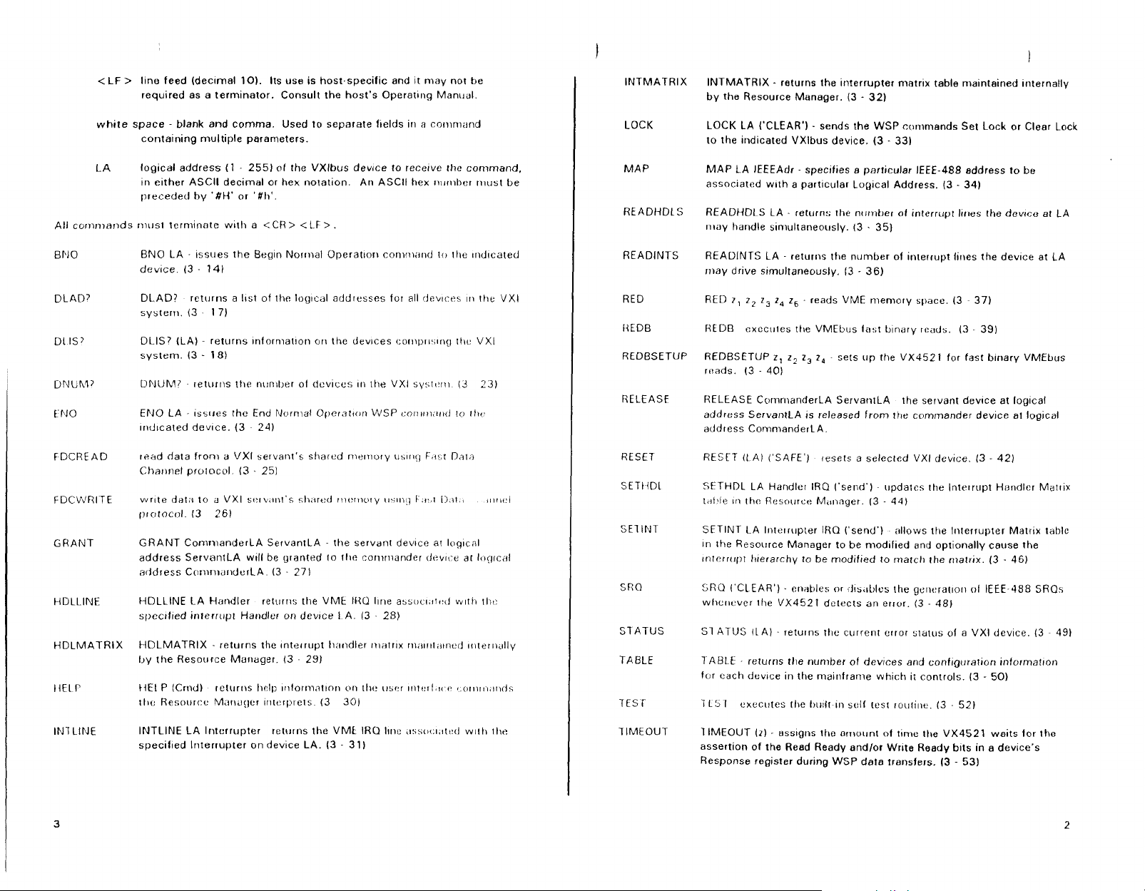
<
LF > l~ne feed (declmal
101.
Its use is host.specific and it may not be
required as a terminator. Consult the host's
Operating
Manual.
white space
-
blank and comma. Used to separate flelds in a coriini;~nd
containing multiple parameters.
LA
logical address
(1
-
255) of the VXlbus device to recerve the corwnand,
In either ASCll decimal or hex notation. An ASCll hex riirrnl~er rnust be
preceded by
'#H'
or '#li'.
All cornmands niusl terminate
with
a <CR
>
<LF
>.
81.10
DL
AD?
DL IS?
DNUR47
€NO
FDCREAD
F
DCWRITE
GRANT
HDLLINE
HDLMATRIX
!{ELI'
INS LINE
BNO LA
-
Issues the Beqn Normal Operat~orr cornor,irrtI to 111e ~ncl~cated
dev~ce (3
-
141
DLAD?
returns a lrst of the log~cdl addresses for all tlev~crs In the
VXI
systern.
(3
17)
DLIS? (LA) returns ~nforniatron on the dev~ces cor~ip~i~,~rrg
ttrt.
VXI
system. (3
-
181
DNUM?
-
returns the nmher ol dcvlccs
111
[lie VXl syst~!rii
(3
23)
EPJO LA - lsstles the End Nornial Operntrciri WSP r:or~t~iia~ttl
ro
tlic.
~r~d~cated deuce. (3 241
read data from a VXI servant's shared riieniory us111~j F.i:,r Daln
Cliarrnel prolocol. (3
.
25)
GRANT ComnianderLA ServantLA
-
the servanl dewce at loglcal
address ServantLA will be granted to t11e coniriiander tlevtce at I<~g~c;il
address Cornri~clnderLA.
(3
-
271
HDLLINE LA Handler returns the
VME
IHU lhrre assoc1.9r1:d w~tli tht:
specrfred interrupt Handler on devrce
I
A. 13 . 28)
HDLMATRIX
-
returns the Interrupt Iial~dler nralrtx rnalr~li~~ned ~~~rer~idlly
IJ~
the Resource Manager.
(3
-
291
INTLINE LA lriterrupter
returns the VMk IRQ Ilnc ,issot:~,~tt:d w~tli the
specifled lriterrupter on device LA. (3
-
311
INTMATRIX
LOCK
MAP
READINTS
RED
HEDB
REDBSETUP
RELEASF
RESET
SETIIDL
SRO
S7
ATUS
TABLE
TEST
TIMEOUT
1
INTMATRIX - returns the interrupter matrlx table maintained Internally
by the Resource Manager.
(3
-
32)
LOCK LA ('CLEAR')
-
sends the WSP cwirnands
Set
Lock or Clear Lock
to the indicated VXlbus device. (3
-
331
MAP LA IEEEAdr
-
specrfies 8 particular IEEE-488 address to be
associated
with
a partrcular Log~cal Address.
(3
-
34)
READHDLS LA
-
returns the ntrtnber ol interrupt Ircres the devicu
at
LA
rilay handle siniultaneously. I3 . 35)
READINTS LA
-
returns the number of interrupt lines the dev~ce at
LA
rimy drive simultaneously.
13
-
36)
RED
7,
z,
z,
2,
z6
-
reads VME nieniory space. 13
37)
REDB cxccules tlre VMEbus last b~nary rcads.
(3
-
39)
REDBSETUP
z,
z2
z,
z,
-
sets up the VX4521 for fast blnary VMEbus
reads. (3
-
401
RELEASE ComnlanderLA ServantLA
the servant dev~ce at log~cal
address ServantLA
IS
released from the commander devrce at logical
address ComnianderLA.
RESET
(1
A1
('SAFE']
cesets a selected VXI device. 13
-
42)
SETHDL LA Handler IRQ ('send')
-
updates 11le Interrupt Hsridler Matl~x
tdllie in (ha Reso~rrce M,~nnger. (3
-
44)
SFTINT LA Irilt:lrup!er IRQ ('send')
allows the Interrupter Matrix table
In
the Resource Manager to be modlfied and optionally cause the
Interrupt trrerarchy to be modified to march the rnatrix.
(3
-
461
SRU ('CLEAR')
-
enables or ~~Is~IOIL'S the geric:ratlori
ol
IEEE-488 SRQs
wlicl~cver the VX4521 detects an error. (3
-
48)
Sl
ATUS
(LA) - returns the current error status of a VXI device.
(3
-
491
TABLE
-
returns the number of devrces and conf~guration informatron
for each devrce in the mainframe which it controls. (3
-
50)
7
LS1
cxecules the 0~11lt
111
SO/(
test ~ouli~re. (3 - 52)
TIMEOUT (2)
-
assigns the ornount of time the VX4521 waits for the
assertion of the Reed Ready andlor Write Ready bits in a device's
Response register during WSP data transfers.
(3
-
53)
Artisan Technology Group - Quality Instrumentation ... Guaranteed | (888) 88-SOURCE | www.artisantg.com
Page 8
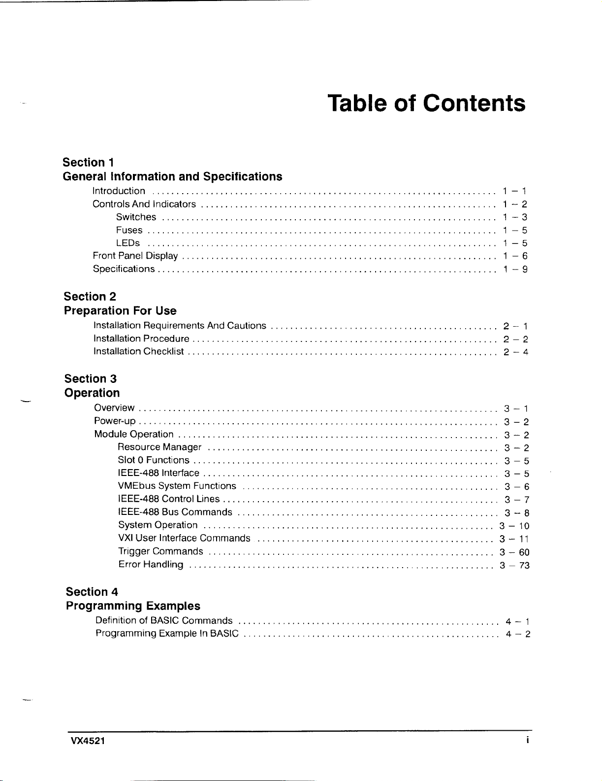
Table
of
Contents
Section
1
General Information and Specifications
Introduction
......................................................................
1
.
1
Controls And Indicators
............................................................
1 . 2
Switches
....................................................................
1
3
.
Fuses
.......................................................................
1
.
5
LEDs
................................................................
1 . 5
FrontPanelDisplay
................................................................
1
.
6
.
.....................................................................
Specifications
1
9
Section
2
Preparation For Use
.
Installation Requirements And Cautions
..............................................
2
1
.
Installation Procedure
..............................................................
2
2
.
Installation Checklist
...............................................................
2
4
Section
3
.
Operation
.
Overview
.........................................................................
3
1
Power-up
.........................................................................
3
.
2
.
Module Operation
.................................................................
3
2
...........................................................
ResourceManager
3-
2
.
..............................................................
SlotOFunctions
3
5
IEEE-488lnterface
............................................................
3
-5
.
VMEbus System Functions
....................................................
3
6
.
IEEE-488 Control Lines
........................................................
3
7
.
IEEE-488 Bus Commands
.....................................................
3
8
.
System Operation
...........................................................
3
10
.
VXI User Interface Commands
...........................
,
....................
3
11
Triggercommands
..........................................................
3
.
60
.
ErrorHandling
..........................................................
3
73
Section
4
Programming Examples
Definition of BASIC Commands
.....................................................
4
.
1
.
Programming Example In BASIC
....................................................
4
2
Artisan Technology Group - Quality Instrumentation ... Guaranteed | (888) 88-SOURCE | www.artisantg.com
Page 9
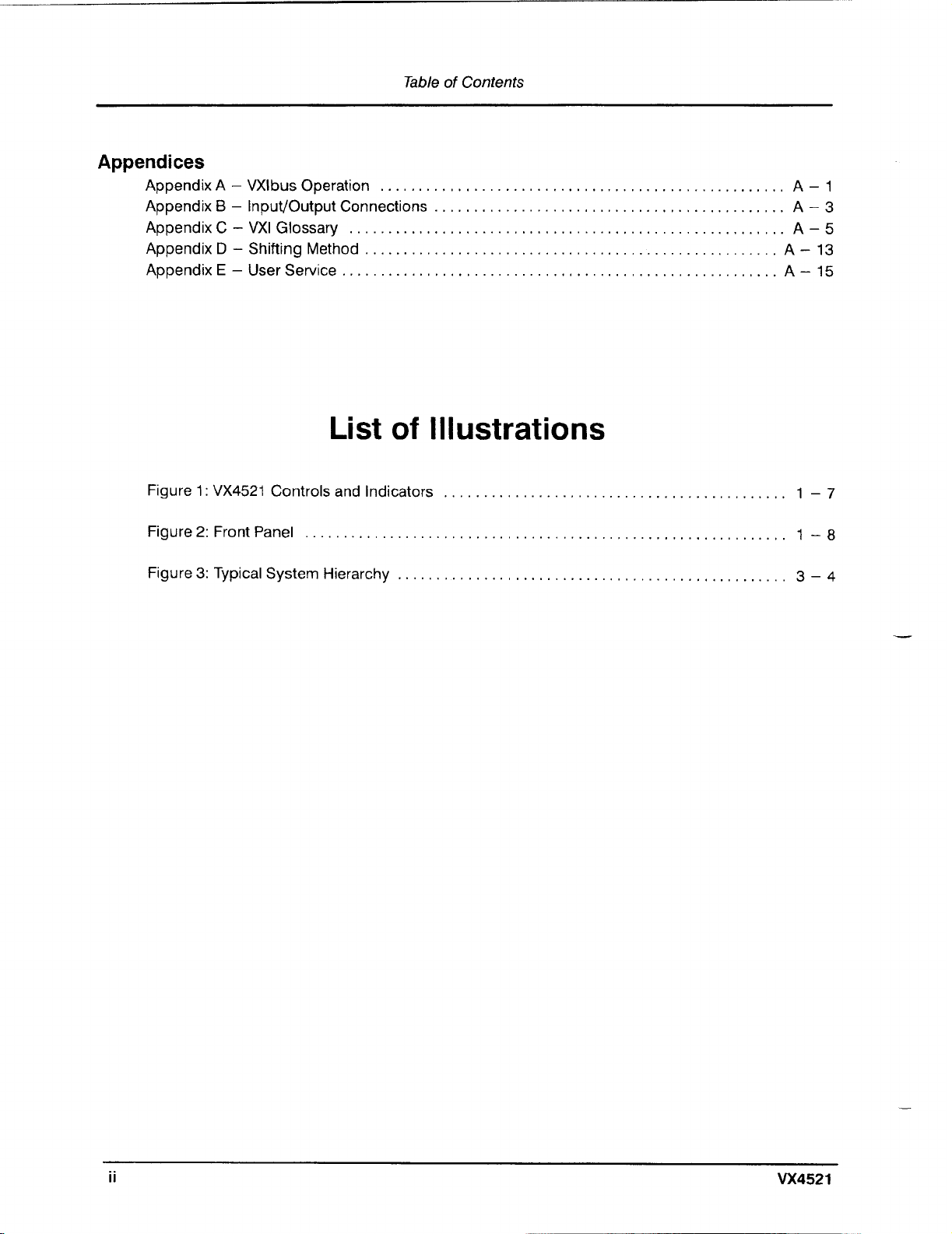
Table
of
Contents
Appendices
.
Appendix A . VXlbus Operation
....................................................
A
1
.
.
Appendix
B
Input/Output Connections
.............................................
A
3
.
Appendix
C
.
VXI Glossary
........................................................
A
5
.
Appendix
D
.
Shifting Method
.....................................................
A
13
.
Appendix
E
.
User Service
........................................................
A
15
List
of
Illustrations
.
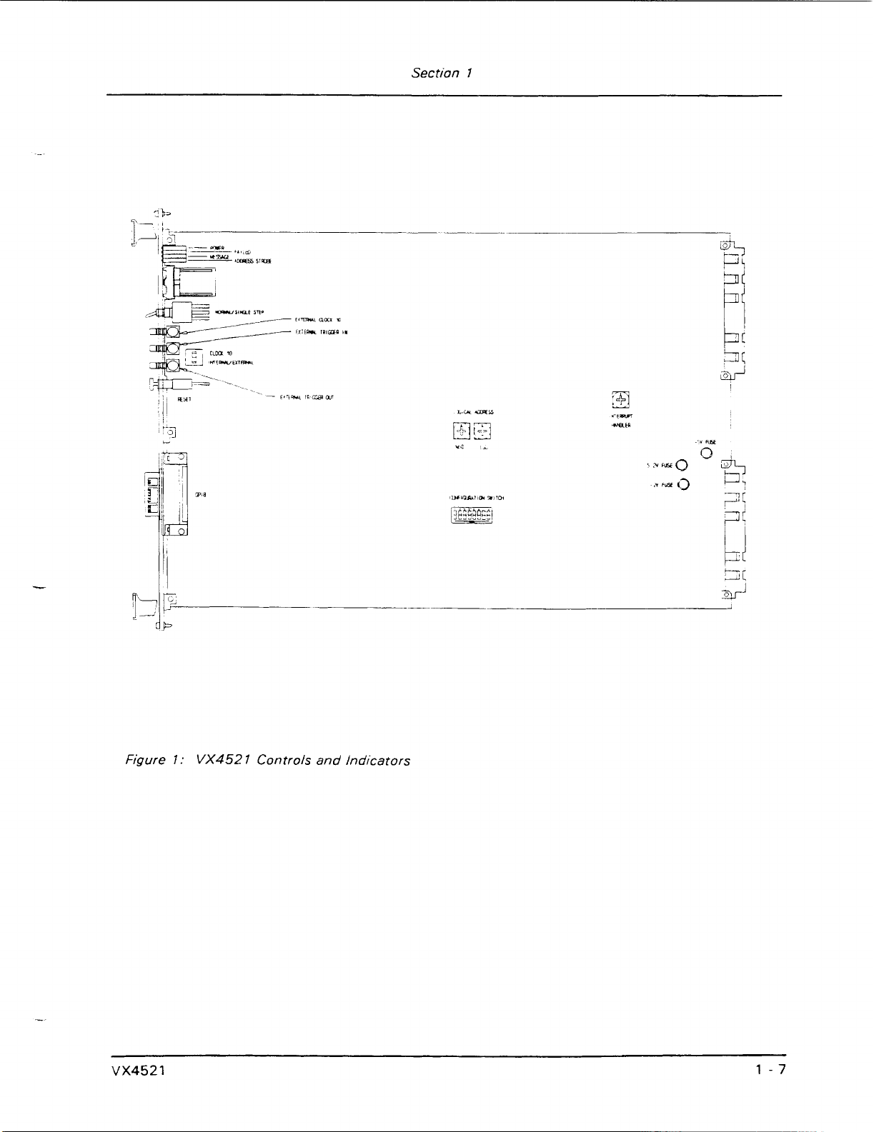
Figure
1
:
VX4521
Controls and Indicators
............................................
1
7
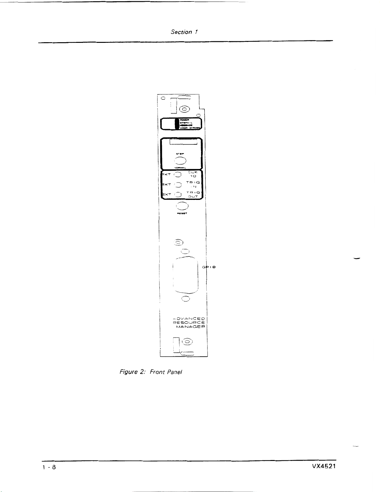
Figure
2:
Front Panel
..............................................................
1
.
8
Figure
3:
Typical System Hierarchy
..................................................
3
-
4
Artisan Technology Group - Quality Instrumentation ... Guaranteed | (888) 88-SOURCE | www.artisantg.com
Page 10
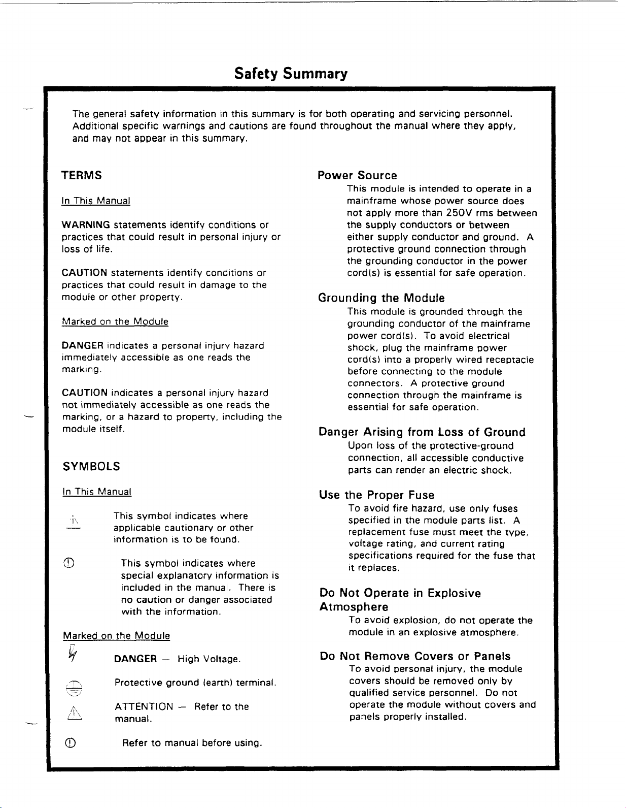
Safety
The general safety information in this summary is for both operating and servicing personnel.
Additional specific warnings and cautions are found throughout the manual where they apply,
and may not appear in this summary.
Summary
TERMS
In This Manual
WARNING statements identify conditions or
practices that could result in personal injury or
loss of life.
CAUTION
practices that could result in damage to the
module or other property.
Marked on the Module
DANGER
immediately access~ble as one reads the
marking.
CAUTION indicates a personal injury hazard
not immediately accessible as one reads the
marking, or a hazard to property, including the
module itself.
statements identify conditions or
indicates a personal injury hazard
SYMBOLS
Power Source
This module is intended to operate in a
mainframe whose power source does
250V
not apply more than
the supply conductors or between
either supply conductor and ground.
protective ground connection through
the grounding conductor in the power
cord(s) is essential for safe operation.
rms between
Grounding the Module
This module is grounded throuah the
grounding conductor of the mainframe
power cordls). To avoid electrical
shock, plug the mainframe power
cordts) into a properly wired receptacle
before connecting to the module
A
connectors.
connection through the mainframe is
essential for safe operation.
protective ground
Danger Arising from Loss of Ground
Upon loss of the protective-ground
connection, all accessible conductive
parts can render an electric shock.
A
In This Manual
I
:
-
a
Marked on the Module
k
-\
-
\s/
h
A
0
This symbol indicates where
applicable cautionary or other
information is to be found.
This symbol indicates where
special explanatory information is
included in the manual. There is
no caution or danger associated
with the information.
DANGER
Protective ground (earth) termmal.
ATENTION - Refer to the
manual.
Refer to manual before using.
-
High Voltage.
Use
the Proper Fuse
To avoid fire hazard, use only fuses
specified in the module parts list. A
replacement fuse must meet the type,
voltage rating, and current rating
specifications required for the fuse that
it
replaces.
Do Not Operate in Explosive
Atmosphere
To avoid explosion, do not operate the
module in an explosive atmosphere.
Do Not Remove Covers or Panels
To avoid personal injury, the module
covers should be removed only by
qualified service personnel. Do not
operate the module without covers and
panels properly installed.
Artisan Technology Group - Quality Instrumentation ... Guaranteed | (888) 88-SOURCE | www.artisantg.com
Page 11
Advanced
Resource
Manager
Introduction
The VX4521 Advanced Resource Manager Module is a printed circuit board assembly
for use in the slot
such as the VX1400
to the VXlbus System Specification for a Resource Manager, Slot
488 lnterface Device for a C size module. The VX4521 performs three functions
critical to the proper operation of a VXlbus system:
1)
2)
Section
General
and
0
position of a mainframe conforming to the VXlbus Specification,
C
size mainframe used in the Tektronix IAC System.
it is the VMEbus system controller required by the VMEbus Specification;
it prov~des both the VXlbus Resource Manager and Slot 0 functions required by
the VXlbus Specification;
Information
Specifications
It
conforms
0
Device, and IEEE-
1
it acts as the communications interface between the station computer and the
3)
VXlbus chassis (VX1400 Mainframe) using the iEEE-488 General Purpose
lnterface Bus.
As
the VMEbus Controller, the VX4521 Module provides the bus arbiter, interrupt daisy
chain driver, bus time out, and system clock driver.
VX4521
the
knowledge is necessary to operate the VX4521 or any VXlbus system in which
installed. The IEEE publication IEEE
operation.
The Resource
located at logical address
system reset to allow individual IAC modules time to perform any required setups and
self tests, the Resource Manager initializes the system and identifies all VXlbus devices
in the system. It then
each device, ~ncluding self test passlfail results, slot location, manufacturer
Artisan Technology Group - Quality Instrumentation ... Guaranteed | (888) 88-SOURCE | www.artisantg.com
makes
all
VMEbus operations transparent to the user, no VMEbus
101
4 (1
987)
Manacler portion of the module is a VXlbus message based instrument
0.
After a maximum five second delay following power-up or
builds a configuration table that contains status information for
It is also a VMEbus master. Since
offers more information on VMEbus
ID,
it
is
model
Page 12
Section
1
code, and other system information. The table may be up-loaded to the station
controller through the IEEE-488 interface.
The Resource Manager also configures
.--
system address maps, sets up the commanaer/servant hierarchies for the system, and
then initiates normal system operation.
The VX4521 Resource Manager conforms to the VXlbus Specification Version
1.3
and
can support VXI devices implementing either the
1.2
or the
1.3
version of the VXlbus
Specification.
The slot
0
functions include a
10
MHz
different~al
ECL
clock driver for the backplane
(CLKIO),
and transceivers for the MODlD lines.
The IEEE-488 Interface portion of the VX4521 Module converts IEEE-488 protocol to
VXlbus instrument protocol.
It routes the incoming
IEEE-488 instructions and data to
the proper instrument (IAC module) in the ma~nframe and returns instrument responses
to the IEEE-488 bus controller. It can also be switch selected to allow the VXIbus
svstem to either assign each IAC module its own IEEE-488 primary address (multiple
primary addressing), or to assign the overall system
a
single IEEE-488 address and each
of the IAC modules a secondary address (single prlmary with multiple secondary
addresses).
The VX4521 Module will execute a self test at power-up, on direction of a VXlbus hard
reset, or on command.
A
VXlbus hard reset cccurs when the Reset switch on the
module's front panel is depressed, asserting the backplane line SYSRST*.
The VX4521
can initiate a VXlbus soft reset in any VXlbus module in the chassis under command of
the system controller.
V
The VX4521 also has extensive trigger control capabilities. Under user control, the
trigger control circuitry can:
transparently pass trigger signals from one trigger line to another,
route
trlgger signals to and from the front panel external trigger spigots,
h
generate trigger events,
t
force the synchronizat~on of an output trigger event to the rising edge of the
VXlbus
CLK10
signal,
convert an Input trlgger event to a s~ngle output signal of a different pulse width,
convert a single input trigger event to a delayed output signal or a pulse train of
variable frequency, with each output pulse
200
ns wide, and
convert a single input trigger event into a continuous square wave of variable
frequency.
Controls And Indicators
The following controls and indicators are provided
to
select and display the functions of
the VX4521 Module's operating environment. See Figures
1
and 2 for their physical
locations.
Artisan Technology Group - Quality Instrumentation ... Guaranteed | (888) 88-SOURCE | www.artisantg.com
Page 13
Switches
IEEE-488 Address Switches
Section
I
L&WL
ADORES
--
HM
ra3
~50
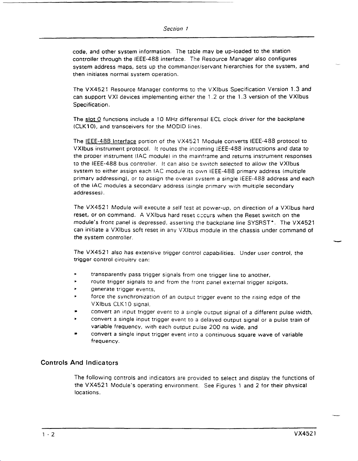
The VX4521 has two hexadecimal rotary switches which determine either the
primary IEEE-488 address of the mainframe and/or the IEEE-488 address of the
VXlbus Resource Manager. This is discussed more fully in the paragraph on
the Configuration swrtch.
M
L
L.
S
S
0
D
A
1
5
Base Phys~cal
Addr.
(d)
(64.10) +49l52 = 49792d
(64*21)+49152
L.A.
=
iogical Address
MSD
=
=
Most
Least
LSD
=
50496d
Sigmflcant Digit
S~gnif~cant Digit
A.
D
Ah
15h
where:
Confisuration Switch
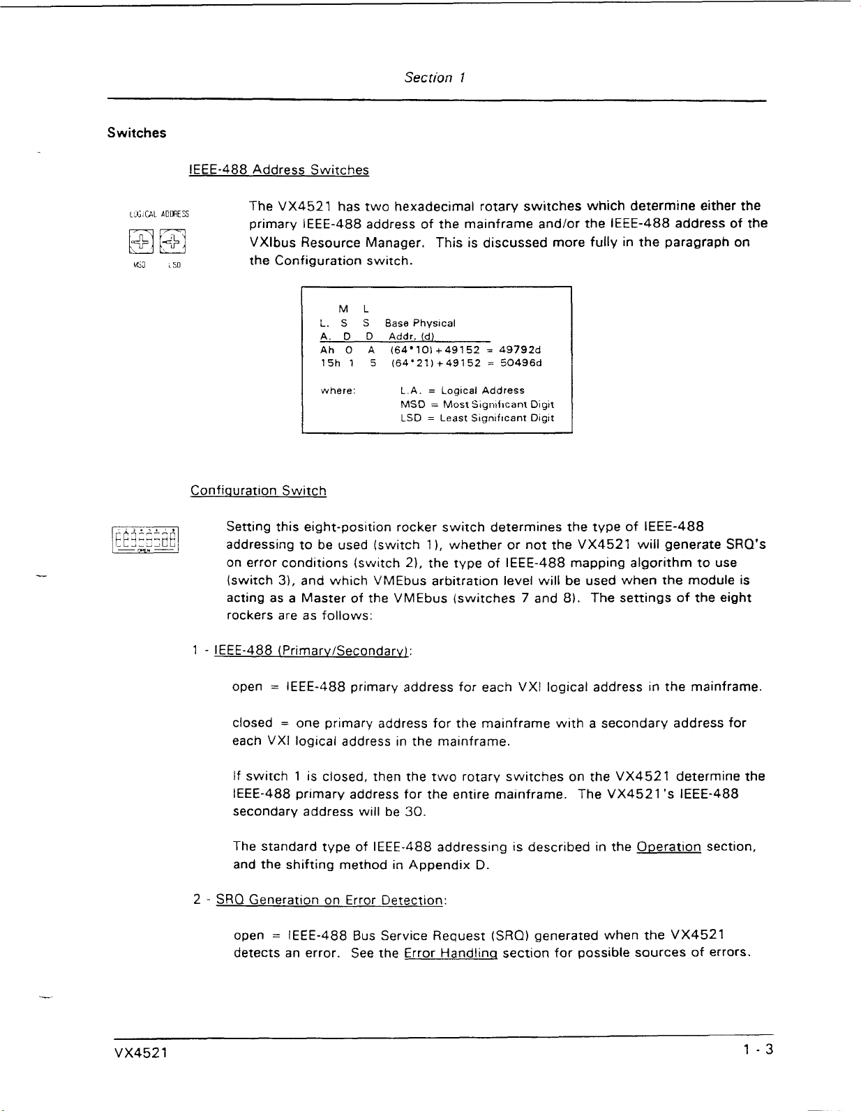
Setting this eight-position rocker switch determines the type of IEEE-488
addressing to be used (switch
on error conditions (switch
(switch
31,
and which VMEbus arbitratron level will be used when the module is
acting as a Master of the VMEbus (switches
11,
whether or not the VX4521
21,
the type of IEEE-488 mapping algorithm to use
7
and 8). The settings of the eight
rockers are as follows:
will
generate SRO's
=
open
closed
each
If switch
IEEE-488 primary address for each VXI logical address in the mainframe.
=
one primary address for the mainframe with a secondary address for
VXI
logical address in the mainframe.
1
is closed, then the two rotary switches on the VX4521 determine the
IEEE-488 primary address for the entire mainframe. The VX4521 'S IEEE-488
secondarv address will be
30.
The standard type of IEEE-488 addressing is described in the O~eration section,
and the shifting method in Appendix
2
-
SRO
Generation on Error Detection:
open
=
IEEE-488 Bus Service Request (SRQ) generated when the VX4521
D.
detects an error. See the Error Handlinq section for possible sources of errors.
Artisan Technology Group - Quality Instrumentation ... Guaranteed | (888) 88-SOURCE | www.artisantg.com
Page 14
Section
7
closed = SRQ generatlon on error detection is disabled.
instruments in the system may still generate an SRQ by sending the VXlbus
Request True event to the VX4521.
3
-
IEEE
Address M~DD~~Q Alaorithm:
closed
method.
open
method.
These two methods are described in the Ooeration section.
7
and
8
These two switches determine which
VX4521 when
the required Bus Request levels is:
=
the
iEEE
address is mapped to the logical address using the direct
=
the IEEE address is mapped to the logical address using the shifting
-
VMEbus Arbitration Level:
Bus
Request level will be used by the
it
requests use of the VMEbus. The setting of rockers 7 and
Rocker Rocker
7
-
closed closed
closed
open closed
open
8
open
open
Level
0
1
2
3
However, other
8
for
El
Ill-ePRuPT
4"OLEil
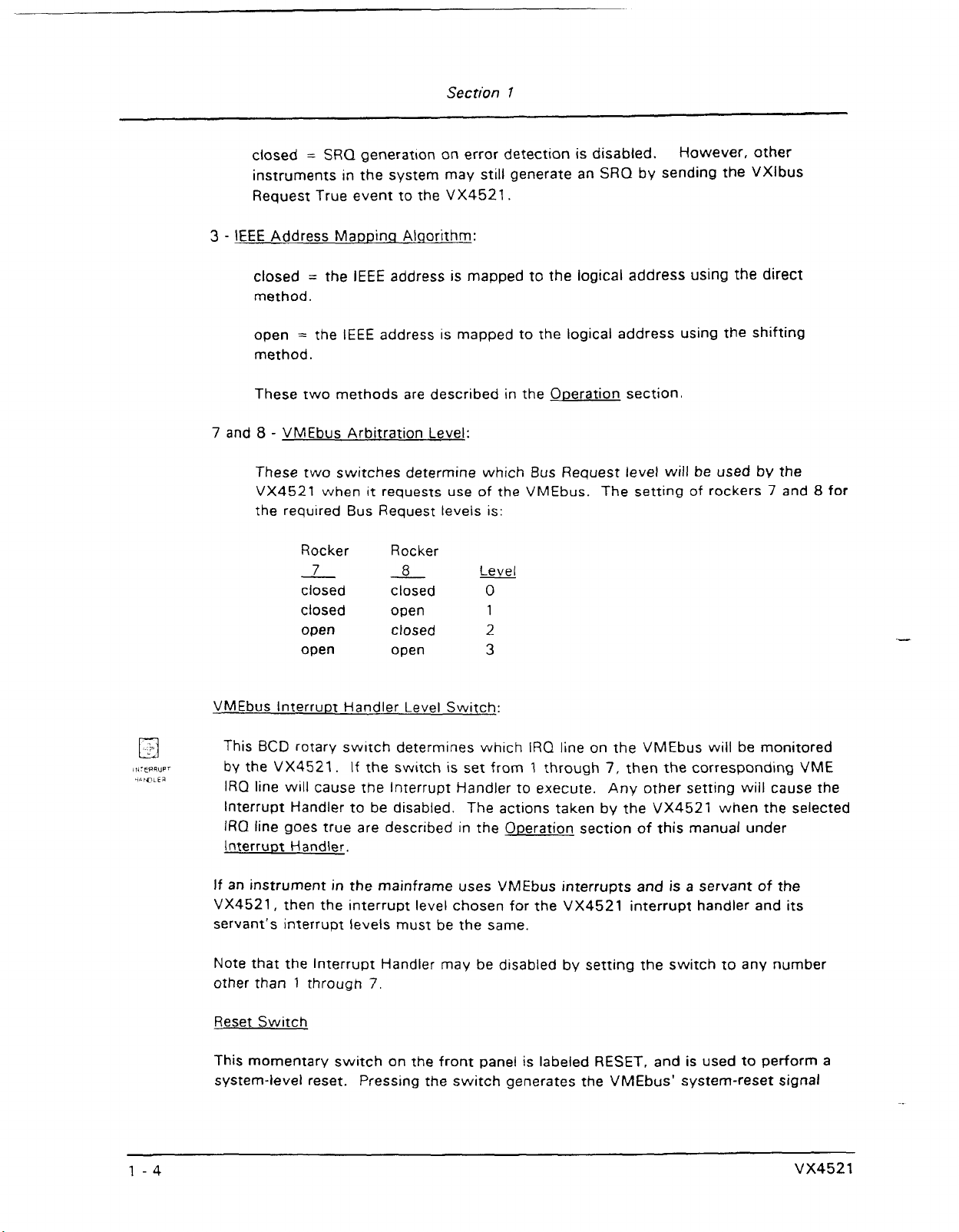
VMEbus Interru~t Handler Level Switch:
This
BCD
rotary switch deterrnlnes wh~ch IRQ line on the VMEbus w~ll be mon~tored
by
the VX4521. If the switch
IRQ line will cause the lnterrupt Handler to execute. Any other settmg wiil cause the
Interrupt Handler to be disabled.
IRO
line goes true are described In the O~eration section of this manual under
Interrum
If
an instrument
VX4521, then the interru~t level chosen for the
servant's interrupt ievels must be the same.
Note that the lnterrupt Handler may be disabled by setting the switch to any number
other than
Reset Switch
This momentary switch on the front panel is labeled
system-level reset. Pressing the switch generates the VMEbus' system-reset signal
Handler.
in
1
through
the mainframe uses VMEbus interrupts and is a servant of the
7.
IS
set from 1 through
The actions taken by the VX4521 when the selected
7,
VX4521
RESET,
then the correspondlng VME
interrupt handler and its
and is used to perform a
Artisan Technology Group - Quality Instrumentation ... Guaranteed | (888) 88-SOURCE | www.artisantg.com
Page 15
Section
7
(SYSRESET') on the VMEbus backplane, and also resets the VX4521 Module's
on-board microprocessor. Pressing this switch causes a VXlbus hard reset.
-
=
-
i
=.
,
I,lx
lo
mtwtrt~~
InternalIExternal
This red double-pole double-throw rocker switch has two positions, labeled
C2. When the switch is
CLK10 on the backplane. When the sw~tch is
CLKl
0
in
the
C1
position, the on-board oscillator is used to drive
in
the
C2
position, the internal
C1
and
oscillator is disconnected from the backplane driver and the SMB external clock
connector on the front panel is connected to the backplane driver.
IEEE-488 Sinsle-ste~ Switch
This front panel 3-position toggle switch is labeled NORMAL (down position), and
(momentary-up position).
It allows the VX4521 Module to act
as
an IEEE-488 bus
STEP
monitor.
When the switch is set to the
speed. When the switch
NORMAL
is
set to the center position, the VX4521 Module does not
position, the IEEE-488 bus runs at its normal
complete IEEE-488 handshaking of the NDAC line for the current IEEE-488 bus cycle
until the switch is pressed to the STEP position. At that time, the bus handshaking is
completed and data from the next bus cycle (when it occurs) is latched into the display.
Bus data is stepped one byte at a time when the Single-step switch is pressed. This
feature allows single stepping of the IEEE bus even if the instrument addressed is not
in
the VX1400 Mainframe.
Fuses
LEDs
Each of the
VX4521 power buses is protected with an on-board fuse to protect other
modules within the VXlbus chassis in the event that an inappropriate voltage is applied
The
to this module's front panel connector.
fuse also protects the module in case of an
accidental shorting of the power busses or any other situation where excessive current
might be drawn.
If any of the fuses open, the power
The VX4521 Module has fuses for
LED (PWRI
+
5V, -5.2V and -2V.
on the front panel will turn off.
If any of the fuses opens, remove the fault before replacing the fuse. Replacement fuse
information is given in the S~ecifications section of this manual.
The following
are visible
at
the top of the
VX4521
Module's front panel to
LEDs
indicate the status of the module's operation:
Artisan Technology Group - Quality Instrumentation ... Guaranteed | (888) 88-SOURCE | www.artisantg.com
Page 16

Section
7
POWER
When
on the backplane:
5V,
present.
SYSFAIL LED
This red LED is
whenever a module in the mainframe asserts the VMEbus backplane signal SYSFAIL*,
including during self test.
a self test or loss of a power rail. The VX4521 will also light this LED if
failure of a module due to a breakdown of communications, even if the SYSFAIL* signal
is unasserted. Reading the status of the VX4521 will extinguish this LED.
MESSAGE LED
When
master or is currently being accessed as a VMEbus slave. The LED appears to stretch
the length of the VMEbus cycle. For example, a five microsecond cycle will light the
LED for approximately
constantly addressed or is constantly accessing the VMEbus.
LED
lit,
this green LED indicates that the following power supply voltages are present
+
5,
-5.2.
and
-2.
+
24, -24,
-5.2V,
or -2V fuses opens, or if any of the other power supply voltages are not
lit
during the five second self test period following power-up and
lit,
this green LED indicates that the VX4521 is either accessing the VMEbus as a
0.2
+
12,
-1
2,
VX4521 Module failures include failure to correctly complete
seconds. The LED will flash if the module is being
This LED
will
go out if the
it
detects a
ADDR STROBE LED
This green LED indicates VMEbus activity by monitoring Address Strobe (AS') on the
VMEbus.
which system component is acting as the bus master. As the duty cycle of AS*
increases, the LED will become brighter.
Front Panel Display
The 4-digit display on the front panel shows IEEE-488 bus data in hexadecimal format
on the two right-most digits and in ASCII format on the left-most digit.
digit from the left will display a "T" when the VX4521 or
currently addressed as
Listener. An "S" will be displayed if an SRQ is pending for any card in the mainframe.
N
0
TE:
It
is lit whenever any type of VMEbus cycle is in progress, regardless of
The second
a
card in the mainframe is
a
The
Talker on the IEEE-488 bus, or an
"S"
will override the "T" and the
"L".
"L"
will be displayed for a
-
Artisan Technology Group - Quality Instrumentation ... Guaranteed | (888) 88-SOURCE | www.artisantg.com
Page 17
'V
Rfi
Figure
7:
VX452 1 Controls
and
indicators
Artisan Technology Group - Quality Instrumentation ... Guaranteed | (888) 88-SOURCE | www.artisantg.com
Page 18
Section
1
-0VINCED
1
MANAGER
I
Figure
2:
Front
Panel
Artisan Technology Group - Quality Instrumentation ... Guaranteed | (888) 88-SOURCE | www.artisantg.com
Page 19

Section
Specifications
Functions:
VXI Resource Manaaer:
Device Type: Message based device.
VXI Resource Manager, Slot
IEEE-488 interface device.
1
0
functions, VMEbus controller, and
Registers:
Logical Address:
Capability:
0
Slot
Functions:
MODID Lines:
Keying:
VMEbus
Funct~ons:
ID.
Device type.
Status.
Response.
Data low.
Signal.
Append~x
See
0
(may not be altered)
A
for definition of reglster contents.
The Resource Manager is fully compliant with the VXlbus
Specifications for a Resource Manager.
10
MHz
ECL
differential; 1 OH 1 16 type driver.
Pulled up by 16.9K ohms; lines may be driven and monitored.
The left side is keyed for
TTL signal levels.
Bus Master:
A24lD16.
Bus Slave: A1 6lD16.
Bus Arbiter:
Prioritized arbiter.
Bus Requestor: Fair requestor.
Arbitration Level:
Switch selectable to anv levei.
Svstem Reset: Driven by on-board power-up monitor, or
driven
by
front panel switch.
Interrupt Handler: Single level capability, switchable to any level.
-.
Bus Time Out
Artisan Technology Group - Quality Instrumentation ... Guaranteed | (888) 88-SOURCE | www.artisantg.com
(BTO):
100
ps.
Page 20
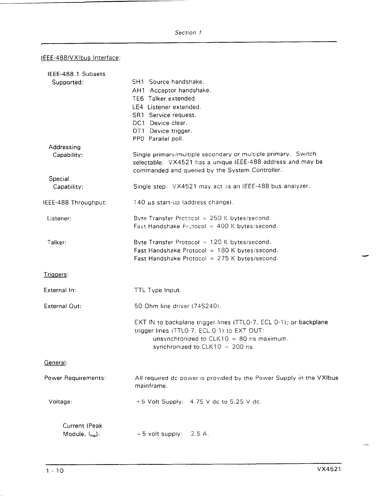
IEEE-4881VXlbus Interface:
IEEE-488.1 Subsets
Supported:
Addressing
Capability:
Special
Capability:
IEEE-488 Throughput:
Section
SH1
Source handshake.
AH
1
Acceptor handshake.
1
TE6 Talker extended.
LE4 Listener extended.
SR1
Service request.
DCl Device clear.
DTI Device trigger.
PPO Parallel poll.
Single prirnary/multiple secondary or multiple primary. Switch
selectable. VX4521 has a unique IEEE-488 address and may be
commanded and queried by the System Controller.
Single step. VX4521 may act 3s an IEEE-488 bus analyzer.
ps start-up (address change).
140
Listener:
Talker:
Triaaers:
External In:
External Out:
General:
Power Requirements:
Byte Transfer
Fast
Handshake F;~:tocol - 400 I< bytesisecond
Byte Transfer Protocol
Fast Handshake Protocol
Fast Handshake Protocol
Prct?col
=
250 I< byteslsecond.
=
120 I< byteslsecond.
=
180
I<
bytesisecond.
=
275 I< bytesisecond.
TTL Type Input.
50 Ohm line driver
EXT
IN
to
backplane
trigger lines
ITTLO-7,
unsynchronized to CLI<10
synchronized to CLI<10
(74S2403.
trigger
lines (TTLO-7,
ECL
0-1)
to EXT OUT:
=
80 ns maximum.
=
200 ns.
ECL
0-1
);
or backplane
All required dc power is provided by the Power Supply in the VXlbus
mainframe.
Voltage:
Current (Peak
Module, I,,):
5.25
V
+5
Volt Supply:
Artisan Technology Group - Quality Instrumentation ... Guaranteed | (888) 88-SOURCE | www.artisantg.com
4.75 V dc to
dc.
Page 21
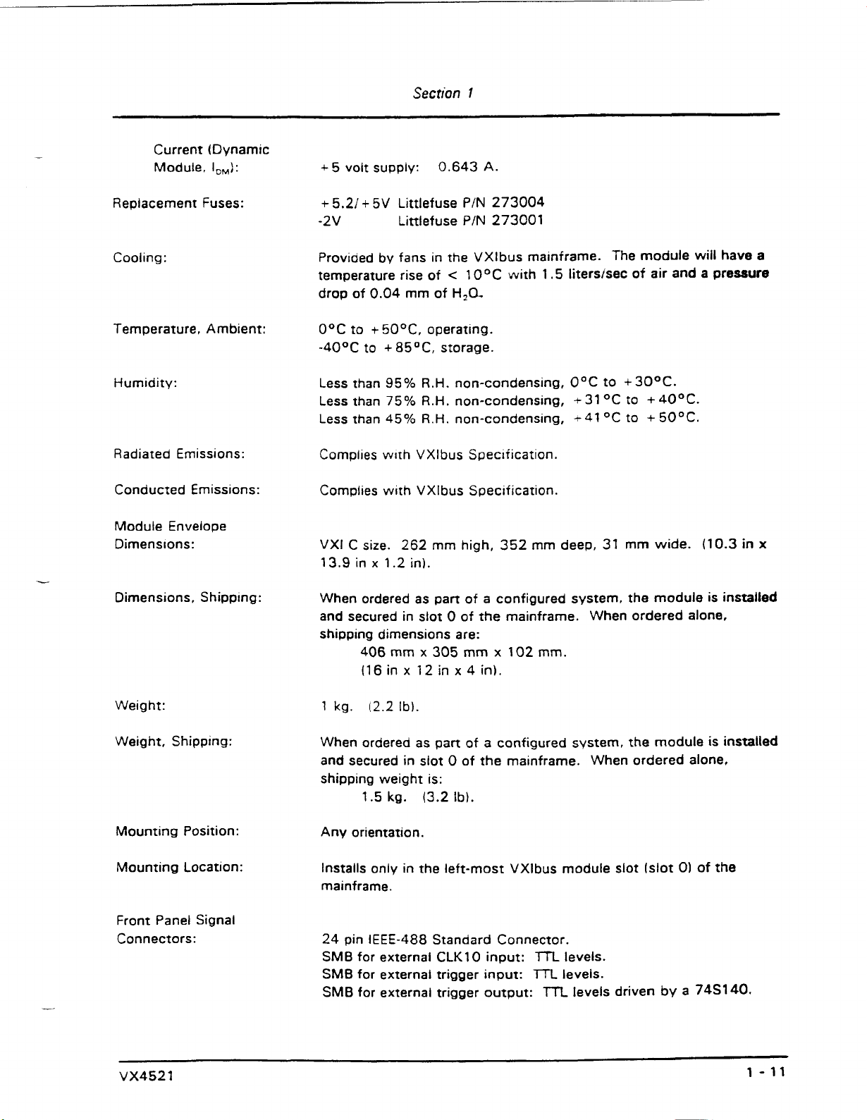
Current (Dynamic
Module.
Replacement Fuses:
I,,):
+
5
volt supply:
+
5.21
-2V
+
5V
Section
0.643
Littlefuse
Littlefuse
I
PIN
P/N
A.
273004
273001
-
Cooling:
Temperature, Ambient:
Humidity:
Radiated Emissions:
Conducted Emissions:
Module Envelope
Dimens~ons:
Dimensions. Shippmg:
Provided by fans in the VXlbus mainframe. The module will have
temperature rise of
drop of 0.04 mm of
O°C to
-40°C to
Less than 95%
Less than
Less than
Complies
Complies with VXlbus Specification.
VXI
13.9 in x
When ordered as part of
and secured in slot 0 of the mainframe. When ordered alone.
shipping dimensions are:
+
50°C, operating.
+
85OC, storage.
75%
45%
w~th VXlbus Specification.
size.
262
C
1.2
406
mm x 305 mm x 102 mm.
(16in
x 12in x4
<
1
O°C with
H,a
R.H.
non-condensing, O°C to +30°C.
R.H.
non-condensing,
R.H.
non-condensing, + 41
mm high, 352 mm deep,
in).
a
configured system, the module is installed
in).
1.5
litershec of air and a pressure
+
31
OC to + 40°C.
+
OC
31
50°C.
to
mm wide.
(10.3
in
a
x
Weight:
Weight, Shipping:
Mounting Position:
Mounting Location:
Front Panel Signal
Connectors:
Artisan Technology Group - Quality Instrumentation ... Guaranteed | (888) 88-SOURCE | www.artisantg.com
1
kg.
(2.2
Ib).
pan
When ordered as
and secured in slot 0 of the mainframe. When ordered alone,
shipping weight is:
1.5 kg. (3.2
Any orientation.
Installs only in the left-most VXlbus module slot (slot
mainframe.
24
pin
IEEE-488
SMB for external CLK10 input:
SMB
for external trigger input:
SMB
for external trigger output:
of a configured system, the module is installed
Ib).
0)
of the
Standard Connector.
TTL
levels.
lTL
levels.
m
levels driven by a
748140.
Page 22
Software:
Artisan Technology Group - Quality Instrumentation ... Guaranteed | (888) 88-SOURCE | www.artisantg.com
Page 23
Section
2
Preparation
For
Use
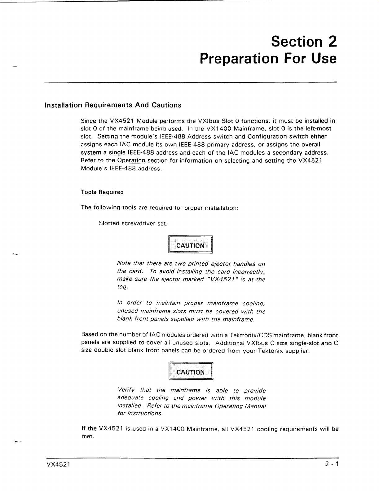
Installation Requirements And Cautions
Since the VX4521 Module performs the VXlbus Slot 0 functions, it must be installed in
slot
0
of the mainframe being used.
In the VX1400 Mainframe, slot
0
is the left-most
slot. Setting the module's IEEE-488 Address switch and Configuration switch either
assigns each IAC module its own IEEE-488 primary address, or assigns the overall
system a single IEEE-488 address and each of the
IAC
modules a secondary address.
Refer to the O~eration section for information on selecting and setting the VX4521
Module's IEEE-488 address.
Tools Required
The following tools are required for proper installation:
Slotted screwdriver set.
Note that there are two printed ejector handles on
the card.
To
avoid installing the card incorrectly,
make sure the ejector marked
"VX452
1
"
is at the
G.
In order to maintain proper mainframe cooling,
unused mainframe slots must be covered with the
blank front panels supplied with the mainframe.
Based on the number of IAC modules ordered with a TektronixiCDS mainframe, blank front
panels are supplied to cover all unused slots. Additional VXlbus
C
size single-slot and
C
size double-slot blank front panels can
be
ordered from your Tektonix supplier.
Verify that the mainframe is able to provide
adequate cooling and power with thts module
installed.
Refer to the mainframe Operating Manual
for instructions.
If the VX4521 is used in a VX1400 Mainframe, all VX4521 cooling requirements will be
met.
Artisan Technology Group - Quality Instrumentation ... Guaranteed | (888) 88-SOURCE | www.artisantg.com
Page 24
Section
2
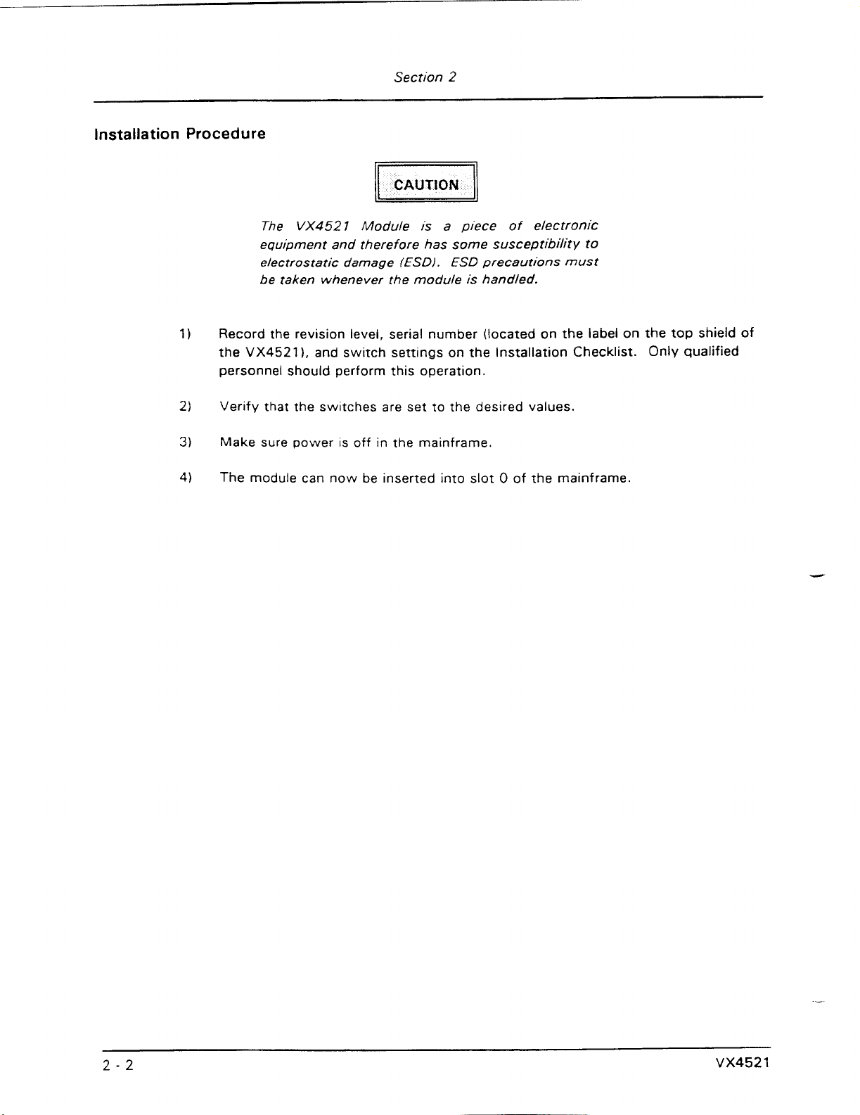
Installation Procedure
The
VX4521
Module is a piece of electronic
equipment and therefore has some susceptibility to
electrostatic damage (ESDI. ESD precautions
must
be taken whenever the module is handled.
Record the revision level, serial number (located on the label on the top shield of
the
VX45211,
and switch settings on the Installation Checklist.
Only
qualified
personnel should perform this operation.
Verify that the switches are set to the desired values.
Make
sure
power is off
in
the mainframe.
The module can now be inserted into slot
0
of the mainframe.
Artisan Technology Group - Quality Instrumentation ... Guaranteed | (888) 88-SOURCE | www.artisantg.com
Page 25
Section
2
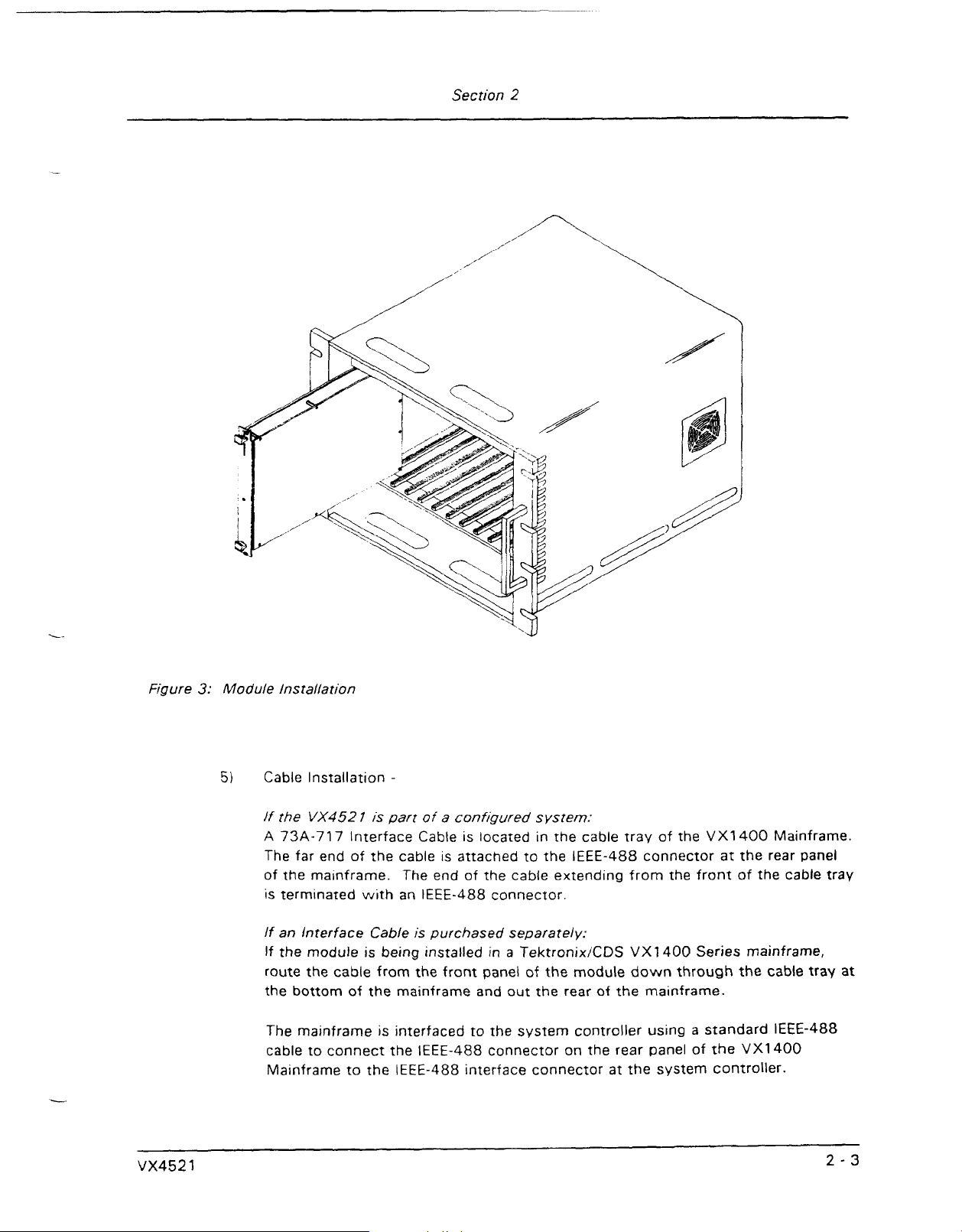
Figure
3:
Module Installation
5)
Cable Installation
lf the
A
73A-717
The
of the mainframe. The end of the cable extending from the front of the cable tray
is terminated with an IEEE-488 connector.
If
an
If the module is being installed in a TektronixKDS VX1400 Series mainframe,
route the cable from the front panel
the bottom of the mainframe and out the rear of the mainframe.
The mainframe is interfaced to the system controller using a standard IEEE-488
cable to connect the IEEE-488 connector on the rear panel of the VX1400
Mainframe to the IEEE-488 interface connector at the system controller.
-
VX452 I is part
lnterface Cable
far end of the cable
interface Cable
of
is
a
configured system:
is
located
is
attached to the IEEE-488 connector at the rear panel
purchased separately:
in
the cable tray of the VX1400 Mainframe.
of
the module down through the cable tray
at
Artisan Technology Group - Quality Instrumentation ... Guaranteed | (888) 88-SOURCE | www.artisantg.com
Page 26
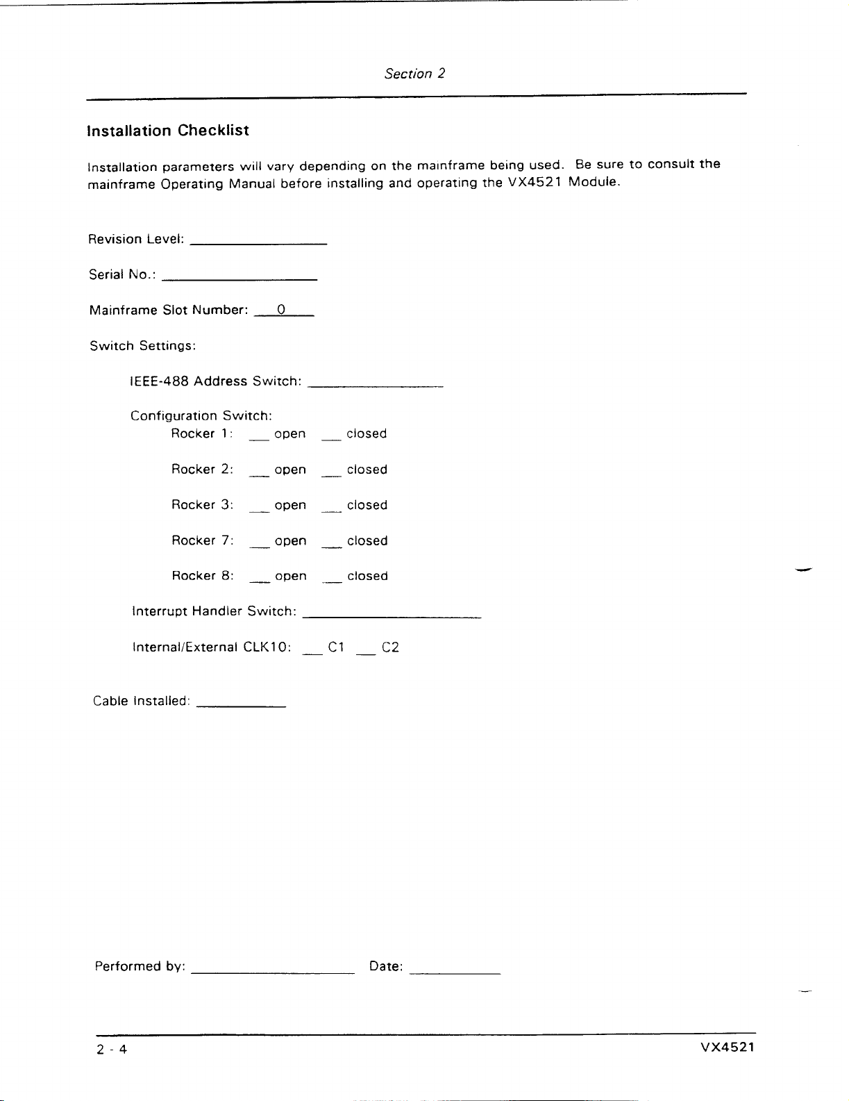
Installation Checklist
lnstallation parameters will vary depending on the ma~nframe being used. Be sure to consult the
mainframe Operating Manual before installing and operating the
VX4521
Module.
Revision Level:
Serial No.:
Mainframe Slot Number:
0
Switch Settings:
IEEE-488 Address Switch:
Configuration Switch:
Rocker
1
:
-
open
-
closed
Rocker
2:
-
open
-
closed
Rocker
3:
-
open
-
closed
Rocker
7:
-
open
-
closed
Rocker 8:
-
open closed
Interrupt Handler Switch:
InternaliExternal
CLK10:
-
c1
-
C2
Cable Installed:
Performed by: Date:
Artisan Technology Group - Quality Instrumentation ... Guaranteed | (888) 88-SOURCE | www.artisantg.com
Page 27
Overview
Section
3
Operation
The VX4521 Module is a C size single slot VXlbus Message Based Word Serial
instrument for use in slot
Configuration Resource Manager, slot
VMEbus system controller functions defined by the VXlbus Specification, Version
The VX4521 has registers that conform to the VXlbus Specification for Message Based
Devices. This set of message based
address
As the VMEbus Controller, the VX4521 Module provides the bus arbiter, interrupt daisy
chain driver, bus time out, and system clock driver. It is also a VMEbus master.
The Resource Manaaer portion of the module is a VXlbus message based instrument
located at logical address
initializes the system and identifies all VXlbus devices in the system. It then builds
configuration table that contains status information for each device, including self test
passlfail results, slot location, manufacturer ID, model code, and other system
information. The table may be up-loaded to the station controller through the IEEE-488
interface. The Resource Manager also configures system address maps, sets up the
commanderlservant hierarchies for the system, and then initiates normal system
operation.
0.
0
of a VXlbus system. The VX4521 contains a Dynamic
0
functions, IEEE-488 interface device, and
registers
0.
After power-up or system reset, the Resource Manager
is for the Resource Manager, at logical
1.3.
a
0
The slot
(CLK1
The IEEE-488 Interface portion of the VX4521 Module converts IEEE-488 protocol to
VXlbus instrument protocol. It routes the incoming IEEE-488 instructions and data to
the proper instrument
to the IEEE-488 bus controller. It can also be switch selected to allow the VXlbus
system to e~ther assign each IAC module its own IEEE-488 primary address (multiple
primary addressing), or to assign the overall system a single IEEE-488 address and each
of the IAC modules a secondary address (single primary with multiple secondary
addresses).
The
trigger control circuitry can:
r
Artisan Technology Group - Quality Instrumentation ... Guaranteed | (888) 88-SOURCE | www.artisantg.com
functions include a
01,
and transceivers for the MODlD lines.
(IAC
VX4521 also has extensive trigger control capabilities.
transparently pass trigger signals from one trigger line to another,
route trlgger signals to and from the front panel external trigger spigots,
10
MHz different~al
module)
in
ECL
clock driver for the backplane
the mainframe and returns instrument responses
Under user control, the
Page 28
Section
3
generate trigger events,
8
force the synchron~zation of an output trigger event to the rising edge of the
VXlbus
CLK10
signal,
convert an input trigger event to a single output signal of a different pulse width,
convert a single input trigger event to a delayed output signal or a
variable frequency, with each output pulse
200
ns wide, and
pulse train
convert a single input trigger event into a continuous square wave of variable
frequency.
of
Following power-up or system reset, the
memory.
red FAILED
message
addressed as
the VXI system.
Module Operation
Resource
Manager
The Dynamic Configuration Resource Manager is a VXI Message Based device at logical
address
Manager begins to initialize the system and build a configuration table containing
system information. The information from the table may be passed through the
488 interface to the system controller using the TABLE command described in the
User Interface Command section of this manual.
The Resource Manager performs the following functions in the order given below after
power-up or system reset:
1.
Identify all VXlbus devices in the system:
After a delay of five seconds, the Resource Manager attempts to read the ID
register at each of the other 255 VXlbus logical addresses.
occurs, then the device at that logical address is present and is added to the
configuration table.
VX4521
will
perform a self test of on-board
The self test will last a maximum of five seconds. If any failure occurs, the
LED
will remam lit after the five second self test period, and an error
will
be sent to the system controller the next time the VX4521 is specifically
a
talker on the IEEE-488 bus. The Resource Manager will then initialize
0.
After a five second delay following power-up or system reset, the Resource
IEEE-
If no bus error
.-.r
2.
Acquire module information:
The Resource Manager determines slot location (using the MODID lines),
Manufacturer
ID,
and Model Code for each device in the mainframe and adds this
information to the configuration table.
Artisan Technology Group - Quality Instrumentation ... Guaranteed | (888) 88-SOURCE | www.artisantg.com
Page 29
Section
3.
Perform Sysfail Test:
If SYSFAIL is asserted, the Resource Manager attempts to determine the
devicek) asserting SYSFAIL. Each device found to be asserting SYSFAIL is
placed in the Soft Reset State with SYSFAIL assertion inhibited.
3
4. Configure the system's
The Resource Manager establishes a system wide CommanderJServant control
hierarchy as described in the VXlbus Specification. This step includes sending
the GRANT DEVICE command to any commander in the mainframe that
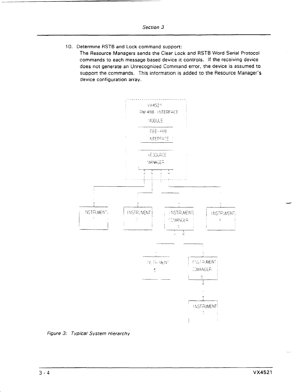
responded to the READ SERVANT AREA query with a non-zero value. See Figure
3
for an example of a typical system hierarchy.
5.
Dynamic configuration:
Perform dynamic configuration of any VXI device that has its logical address set
255.
to
device has its logical address set to 255.
6.
Configure the system's A24 and
The Resource Manager reads the address space requirements of each A24 and
A32 device that was added to the configuration table. If an A24 or A32 device
is present and requires additional address space, then an offset is calculated so
that no two devices' address spaces overlap. This value is written to the
device's Offset register.
Dynamic configuration can only occur if no static configuration VXI
Commander/Servant hierarchies:
A32
address maps:
Foreign devices (with the exception
852
Adapter) are undetectable, since they do not
contain VXlbus configuration registers, and
cause address space overlap problems.
7.
VME
IRQ line allocation:
VME Interrupt Request lines are first allocated to programmable interrupt handler
devices. Then, any remaining lines are allocated to programmable interrupter
devices. The rules for IRO line allocation are defined in the VXlbus Specification
1.3,
version
8.
Identify commander:
The Resource Manager sends the IDENTIFY
instruments in the mainframe which are servants
VMEbus master capability. This allows devices to use VXlbus signaling rather
than interrupts for sending events and responses to the VX4521.
9.
Initiate normal operation:
The Resource Manager sends the BEGIN NORMAL OPERATION command to all
the Message Based Devices the VX4521 controls, in order of increasing logical
address.
section C.4.1.5.
of
the
CDS
COMMANDER
of
73A-
may
command to all
the VX4521 and which have
Artisan Technology Group - Quality Instrumentation ... Guaranteed | (888) 88-SOURCE | www.artisantg.com
Page 30
10.
Determine
Section
RSTB
and Lock command support:
3
The Resource Managers sends the Clear Lock and RSTB Word Serial Protocol
commands
to
each message based device
it
controls.
If
the receiving device
does not generate an Unrecognized Command error, the device is assumed to
support the commands. This information is added to the Resource Manager's
device configuration array.
Figure
3:
Typical System Hierarchy
Artisan Technology Group - Quality Instrumentation ... Guaranteed | (888) 88-SOURCE | www.artisantg.com
Page 31

Slot 0 Functions
The slot
are hidden within the Resource Manager. The slot
MHz
differential ECL clock driver for the backplane) and transceivers for the MODlD
lines.
IEEE-488 Interface
The IEEE-488 Interface converts
routes the incoming IEEE-488 data to the proper instrument in the mainframe and
returns instrument responses to the IEEE-488 controller. It does not examine or parse
any IEEE-488 data unless it is specifically addressed to the VX4521.
Section
0
functions required by the VXlbus are supplied by the VX4521 Module and
IEEE-488 protocol to VXlbus instrument protocol.
3
0
functions include
CLKlO
(a
10
It
The Configuration switch setting determines whether the direct or shifting method
be used. The shifting method is discussed in Appendix
DIRECT
IEEE-488 Multiale Primarv Address Maeeinq
When positlon
translated to VXlbus logical addresses as follows:
METHOD
1
of the
The IEEE-488 address of the VX4521 is determined by the setting of the two
hexadecimal rotary switches on the VX4521 Module.
Logical addresses of VXlbus devices, from
488 primary address. If the logical address is 31 or greater, the VX4521 will
assign IEEE-488 addresses in ascending order, filling In unallocated addresses in
the address list. For example:
Module
Loqcal
Configuration
Address
switch is set
IEEE-488
Pr~mary
Aadress
1
w,
to
D.
IEEE-488 addresses are
30,
correlate directly to an IEEE-
will
With a logical address greater than
the module to another slot may change the module's IEEE-488 address. This will
require changes to the user's application program.
It
is
recommended that the logical address chosen for each module be the same as the
slot number, and that the IEEE-488 address selected for the Resource Manager be
greater than
logical address.
Artisan Technology Group - Quality Instrumentation ... Guaranteed | (888) 88-SOURCE | www.artisantg.com
12.
This will allow the module's IEEE-488 address to be the same as its
30,
adding another card to the mainframe or moving
Page 32

Secrion
3
IEEE-488
When Configurati0:-i switch position
Sinale Primarv/Multiole Secondarv Address M~DD~Q
1
to VXlbus logical addresses as follows:
The IEEE-488 primary address for the rnamframe is determined by the setting of
the two hexadecimal rotary
The VX452i
Module is au~omatically assigned secondary address 30. Any other
5,.
-itches
module given logical address 30 will be reassigned.
1
Logical addresses from
to 29 correlate directly to an IEEE-488 secondary
address. Logical addresses greater than
in ascending order, filling in unaiiocated addresses
examole:
Module
Loq~cal
Address Seconaarv Address
is set closed, IEEE-488 addresses are translated
on the VX4521 Module.
29
will be assigned secondary addresses
in
the address list. For
IEEE-498
VMEbus System Functions
As the VMEbus controller, the VX4521 prov~des the VMEbus-arbiter, system-clock
driver, bus-timer, system-reset driver, interrupt-daisy-chain driver, and interrupt handler
functions:
1. Bus Arbiter:
The bus arbiter arbitrates bus requests and grants the bus on four levels,
through 3. Level 3 has the highest priority and level 0 has the lowest priority. If
the level
request, the bus arbiter initiates a bus clear. The VXlbus Specification requires
that the "Fair Requestor" scheme be implemented by modules in the system.
2.
System-clock Driver:
The system-clock driver generates a 16-MHz 50% (nominal) duty-cycle signal.
This clock has no fixed phase relationships with other VMEbus timing.
3.
Bus Timer:
The bus tlrner monitors all VMEbus data transfers and asserts the VMEbus signal
BERR*
negative transition
transition
of
the current bus master
if
a transfer takes longer than 100 ps. The timer is started on the
of
either Data strobe
of
either C .ta strobe.
is
lower than the level of the current bus
(DS1
or DSO) and reset on the positive
0
Artisan Technology Group - Quality Instrumentation ... Guaranteed | (888) 88-SOURCE | www.artisantg.com
Page 33

Section
3
4.
Power-up Reset:
When power is applied to the VX1400 Mainframe, the VX4521 Module provides
a VMEbus system reset for a minimum of
200
ms as defined
in
the VMEbus
Specification.
5, IACK (Interrupt Acknowledge) Daisy-chain Driver:
This circuitry complies with the VMEbus Specification for generating a falling
edge on the IACK daisy-chain driver each time any interrupt handler initiates an
IACK cvcle.
6. lnterrupt Handler:
The VX4521 Module contains an lnterrupt Handler that is enabled when the
lnterrupt Handler switch is set for an IRQ level between 1 and
7,
as described in
the Interrum Handler Switch subsection.
The lnterrupt Handler will execute when
the VMEbus IRQ line that matches the switch setting is active. The lnterrupt
Handler performs the following functions:
a)
It performs a VMEbus Dl
6
interrupt acknowledge cycle to obtain the
STATUSilD of the interrupting device. The interrupting device will return a
16-bit code, where the lower e~ght b~ts contain the ID (logical address) and
the upper eight bits contain the STATUS (cause for interrupt).
b)
If the ID (logical address) is for
a
VXlbus Message Based Device, then step
c) is performed.
Otherwise, the interrupt handler terminates operation.
c) If the Status is a Response (bit 15 set to
01,
then the configuration table is
updated with that device's status. If the Status is an Event (bit 15 set to
11, then the event is handled as defined in the IEEE-488 Interface Device
section of the
VXlbus Specification. If the event was a Request True, then
the IEEE-488
SRO line will be asserted.
IEEE-488 Control Lines
The VX4521 Module's implementation of indiv~dual
follows:
EOI (End Or
ldentifvl
The VX4521 wiil set EOI on the IEEE-488 bu:
EEE-488 bus control lines is as
true when
it
receives data from
a
card that was addressed to talk and the VXI end bit was set (bit 8 of the 16-bit
data transfer is set to a
1).
SRQ (Service Reauestl
The SRQ line on the IEEE-488 bus will be set true when the VX4521 receives the
Request True event from a servant which it controls. It is
set
false when
it
receives the Request False event from that same servant only if no other servant
has sent the Request True event.
The
VX4521 also generates the SRQ signal on error occurrence, if enabled to do
so. The VX4521 can be enabled to generate SRQs on errors in two ways:
Artisan Technology Group - Quality Instrumentation ... Guaranteed | (888) 88-SOURCE | www.artisantg.com
Page 34

Section
3
a) with the SRQ command, or
b) with the VX4521 Configuration switch, which can set the initial mode of
SRQ
generation following power-up.
If the Configuration switch rocker
#2
is open, SROs will be generated whenever
an error is detected. If the Configuration switch rocker #2 is closed, SROs are
not generated on errors. This initial setting for the generation of
SROs can be
modified during operation with the SRQ command.
IFC (Interface Clear)
When the bus controller asserts the IEEE-488 bus IFC line, the
1EEE-488 interface
on the VX4521 Module goes into a quiescent state and is unaddressed as an
active talker or listener. The IFC line is intended to clear the IEEE-488 interface.
and therefore servants
of
the VX4521 are not affected by the IFC line going true.
DAV (Data Valid)
lmplemented per IEEE-488 Standard, 1978
NRFD (Not Readv For
Datal
lmplemented per IEEE-488 Standard, 1978.
NDAC (Not Data Acce~tedl
lmplemented per IEEE-488 Standard, 1978.
REN (Remote Enable)
lmplemented per IEEE-488 Standard, 1978.
ATN (Attention1
lmplemented per IEEE-488 Standard, 1978.
IEEE-488
Bus Commands
The IEEE-488 Specification refers to multiline messages which can be used to obtain
predefined uniform actions from bus instruments. Multiline messages are commonly
referred to as "universal" commands and "addressed" commands. These commands
can only be sent to individual bus instruments by the bus controller (station computer)
when the ATN (attention) line on the bus is true.
The VX4521 response to these
messages is as follows:
Universal Commands
Device Clear
(DCL)
-
When the DCL command is received, the IEEE-488 interface device
sends the VXlbus
CLEAR
command to all VXlbus instruments which are its direct
servants. The CLEAR command is sent using the Word Serial protocol.
Serial Poll Enable (SPE)
-
Polling is a method the IEEE-488 bus controller uses to
determine which instrument on the bus has requested service. When the
SPE
command is received, the
VX4521
enters the Serial Poll Active State (SPAS).
If
secondary addressing is being used, the system controller
musf
be capable of a
serial poll using secondary addresses.
Artisan Technology Group - Quality Instrumentation ... Guaranteed | (888) 88-SOURCE | www.artisantg.com
Page 35

Section
3
Once the serial poll begins, the VX4521 may respond
depending on the capabilities of the VXlbus module requesting service.
1. IF the IEEE-488 controller places a Talk address on the bus,
AND
that Talk address
AND that instrument is IEEE-488.2 compatible
STB
command,
THEN the VX4521 will send the VXlbus READ STATUS
that instrument.
The VX4521 then reads the status byte of that instrument (using the Word
Serial Protocol) and returns it to the IEEE-488 controller.
2. IF the IEEE-488 controller places a Talk address on the bus,
AND
that Talk address & for an instrument in the mainframe
AND that instrument is not IEEE-488.2 compatible
AND does not respond to the READ
THEN IF that instrument is the one that sent the Request True event to the
VX4521,
THEN the VX4521 will return a hexadecimal 40 to the IEEE-488 controller
6
set), or
(bit
ELSE an ASCII null (hex
for an instrument in the mainframe,
STB
command,
0)
is
returned to the controller.
in
one of two
OR
responds to the READ
ways,
BYTE
command to
Serial
Poll Disable (SPD)
the IEEE-488 SPAS state and return to the IEEE-488 idle state.
occur for the instrument which sent the Request True event to the
no other instrument has sent a Request True event to the VX4521, then the
line on the bus is set false.
Addressed Commands
Group Execute Trigger (GET)
interface device sends the VXlbus
which are addressed to listen and have trlgger capability indicated by the Trigger
bit in their VXlbus Protocol register. The TRIGGER command is sent using the
Word Serial protocol.
hardware triggers when an IEEE-488 GET is received. Refer to the
Commands section.
Selected Device Clear
interface device sends the VXlbus CLEAR command to all VXlbus instruments
which are addressed to listen. The CLEAR command is sent using the Word
Serial protocol.
Service
The SRQ line on the IEEE-488 bus is set by bus instruments whenever they require
service from the system controller. If the SRQ is set true, the system controller will
perform a serial poll to determine the cause of the SRO. The VX4521 will set the IEEE-
Request (SRQ) O~eration
-
When the SPD command is received, the VX4521
-
When the GET command is received, the IEEE-488
(SDC)
TRIGGER
VX4521 can also be programmed to generate VXlbus
The
-
When the SDC command is received, the IEEE-488
command to all VXlbus instruments
will exit
If a serial poll did
VX4521
SRQ
Trinaer
Artisan Technology Group - Quality Instrumentation ... Guaranteed | (888) 88-SOURCE | www.artisantg.com
Page 36

488 bus SRQ line true, if enabled to do so by either the Configuration switch (rocker
position
event from any of its servant modules in the mainframe. The Request True event may
be sent to the VX4521 with VMEbus interrupts or with VXlbus signaling.
The conditions under which modules generate Request True events are described in the
Operating Manual for the individual modules.
when a serial poll occurs for the instrument which sent the Request True event to the
VX4521
System Operation
If a SYSFAIL occurs, the VX4521 will send a Sysfail Inhibit to each VXlbus device in
turn. When SYSFAIL goes inactive, the
Sysfail lnhibit as the source of the SYSFAIL. Once determined, the failed device is
placed in the Soft Reset state with Sysfail assertion inhibited, as defined by the VXlbus
Specification.
Sysfail management has two phases: Power-Up Sysfail management and Runtime
Sysfail management:
Section
2)
or the software command SRQ, when
and
no other instrument has sent a Request True event to the VX4521.
3
it
detects a VXlbus Request True
The VX4521 will set the SRQ line false
VX4521 identifies the device that last received
Power-up Sysfail Management:
If Sysfail is detected at power up, the VX4521 handles the situation as described
above. That is,
to inhibit it, and generates appropriate error messages.
Runtime Sysfail Management:
Runtime Sysfail management is more complex. If no V1.3 commanders are
present in the system, then Sysfail processing occurs as in a V1 .2 system (as
described above). If V1 .3 commanders are present, the resource manager waits
two seconds to allow the commanders to perform their required Sysfail
processing. If Sysfail is stdl asserted after two seconds, the VX4521 assumes
the device asserting Sysfail is not a servant of a V1.3 commander and attempts
to remove Sysfail, as
above.
Alternative Sysfail Management:
An alternative Sysfail interrupt handler can be installed that only inhibits the
generation of the Sysfail signal and does not place the device into the 'Safe
State'. This Sysfail management is useful during device development, debug or
whenever the user does not want a failed device placed into the 'Safe State'.
The alternative Sysfail handler can be installed by issuing the following command
to the VX4521:
The alternative Sysfail handler remains in effect until the system is reset.
possible to reset the system and maintain the alternative Sysfail handler. See the
description of the Reset command.)
it
tries to determine which device is asserting SYSFAIL, then tries
descr~bed in the Power-up Sysfail management paragraph
0
"SetHdl
11 1 ",
where 0 is the logical address of the VX4521.
(It
is
Artisan Technology Group - Quality Instrumentation ... Guaranteed | (888) 88-SOURCE | www.artisantg.com
Page 37

Section
VXI
User Interface Commands
.
The VX4521 has its own unique IEEE-448 address, as described
subsection.
recognize certain ASCII strings that will cause an action to occur or cause a response to
be
formatted and returned to the
addressed as a Talker on the bus.
When the
VX4521 is addressed as a Listener on the IEEE-488 bus,
IEEE-488
3
in
the Switches
controller the next time the VX4521 is
it
will
A summary of the VX4521 Module's commands is listed below
This is followed by detailed descriptions of each of the commands.
The subset of Trigger commands is described separately
section, although they are used in the same way as these more general commands.
Command Action
BN
0
DLAD? returns
DLIS? returns information on the devices compris~ng the VXI system.
DNUM? returns the number
EN0
FDCREAD
FDCWRITE
issues the Begin Normal Operation command to the indicated device.
a
i~st of the log~cal addresses for all dev~ces in the VXI system.
of
devices in the VXI system.
issues the End Normal Operation
read data from a VXI servant's shared memory using Fast Data Channel
orotocol.
write data to a VXI servant's shared memory using Fast Data Channel
protocol.
WSP
in
command to the indicated device.
in
alphabetical order.
the Triauer Commands
GRANT
HDLLINE
HDLMATRIX
HELP
INTLlNE
specifies that the servant device at logical address ServantLA be granted to
the commander device at logical address
returns the VME interrupt request line (IRQ) associated with the specified
interrupt Handler on device LA.
returns the interrupt handler matrix maintained internally by the Resource
Manager.
returns help information on the user interface commands the Resource
Manager interprets.
returns the VME interrupt request line (IRQ) associated with the specified
Interrupter on device LA.
CommanderLA.
Artisan Technology Group - Quality Instrumentation ... Guaranteed | (888) 88-SOURCE | www.artisantg.com
Page 38

Section
3
INTMATRIX
returns the interrupter matrix table maintained internally by the Resource
Manager.
LOCK
sends the Word Serial Protocol commands SET LOCK or CLEAR LOCK to
the indicated
VXlbus device.
MAP
specifies
a
particular IEEE-488 address to be associated with a particular
Logical Address.
READHDLS
returns the number of interrupt lines the device at LA may handle
simultaneously, i.e.
the number of interrupt handlers on that device.
READINTS
returns the number of interrupt lines the device at LA may drive
simultaneously, i.e. the number of interrupters on that device.
RED
reads VME memory space
REDB
executes the VMEbus fast binary reads.
REDBSETUP
sets up the VX4521 for fast binary VMEbus reads.
RELEASE
RESET
SETHDL
SETINT
SRQ
STATUS
TABLE
TEST
TIMEOUT
specifies that the servant device at logical address ServantLA be released
I
from the commander device at logical address CommanderLA.
resets a selected VXI device.
updates the Interrupt Handler Matrix table in the Resource Manager.
allows the Interrupter Matrix table in the Resource Manager to be modified
and optionally cause the interrupt hierarchy to be modified to match the
matrix.
enables or disables the generation of IEEE-488
SRQs whenever the
VX4521 detects an error.
returns the current error status of a VXI device.
directs the VX4521 to return the number of devices and configuration
information for each device in the mainframe which it controls.
causes the
VX4521 to execute its built-in self test routine.
assigns
the amount of time the VX4521 waits
for
the assertion
of
the Read
Ready and/or Write Ready bits in a device's Response register during Word
Serial Protocol data transfers.
Artisan Technology Group - Quality Instrumentation ... Guaranteed | (888) 88-SOURCE | www.artisantg.com
Page 39

Section
3
WRT
WRTB
writes to VME memory space.
executes the VMEbus fast binary writes.
WRTBSETUP
sets up the VX4521 for fast binary VMEbus writes.
WSCMD
WSCMD?
The syntax and symbols used in the command descriptions are:
<CR>
sends the specified Word Serial Protocol command to a VXI device.
sends the specified Word Serial Protocol command to a VXI device. The
response value is returned in ASCll decimal format.
(
1
optional parameter
{
}
group of parameters
.
. .
optional repetition
Note that the
represents the carnage return character, decimal
specific and it may not be required as a terminator. Consult the host's
Operating Manual.
0,
{I,
and
...
characters are not part of the command.
13.
Its use is host-
<
LF
>
I,
white space
underlines
represents the line feed character, decimal
it may not be required as a terminator. Consult the host's Operating
Manual.
enclosed characters must be sent as ASCll cahracters.
used to separate fields in a command containing multiple parameters.
white space characters are blank and comma.
the Logical Address parameter, represents the logical address
the VXlbus device, expressed in either ASCll decimal or ASCII hexadecimal
notation. If an ASCll hex number is used, it must be preceded by
'#h'.
Data returned by the VX4521 to the system controller through the
488
bus is underlined in the examples that follow each command.
10.
Its use is host-specific and
(1
-
255)
'#HI
IEEE-
Valid
of
or
Artisan Technology Group - Quality Instrumentation ... Guaranteed | (888) 88-SOURCE | www.artisantg.com
Page 40

Section
3
Command: BNO (Begin Normal Operation)
Syntax: BNO LA<CR>
<LF>
Purpose: This command issues the BEGIN NORMAL OPEFiATlON Word Serial Protocol
command to tne device at logical address
LA.
Description: LA
represents the logical address
(1
-
255)
of the VXlbus device to receive the
command, expressed in either ASCll decimal or ASCII hexadecimal
notation. If an ASCll hex number is used,
it
must be preceded by
'#H'
or
'#hl.
In most simple systems, this command would not be required.
The
VX4521
sends
a
BEGIN
NORMAL
OPERATION Word Serial Protocol command to each of
its direct message based servants followmg the power-up sequence. The
BNO
command would typ~cally
be
used to restart operation if an End Normal Operation
command had been sent to
a
module to allow reconfiguratlon of commander1
servant or Interrupt
hierarchies.
Example:
Errors:
BNO
14<CR>
<LF>
This sends the BNO command to the VXlbus device with a logical address of
decimal
14.
If the selected device does not exist or is not a message based servant of the
-
VX4521,
an Invalid Logical Address error is generated.
If the device's Status register indicates that it has not passed (or completed) the
self test then a Device Has Not Passed Self Test error is generated.
If the device has its Sysfail Inhibit bit set, then
a
Device Has Sysfail Inhibited
error
IS
generated.
If
the device has its Reset bit set, then a Device
Is
In Reset State error is
generated.
Artisan Technology Group - Quality Instrumentation ... Guaranteed | (888) 88-SOURCE | www.artisantg.com
Page 41

Section
3
Command: BUSTIME (Assign IEEE-488 Bus Settling Time)
Syntax:
Bustime (488BusTime)
<
CR
>
<
LF
>
Purpose:
This command modifies the IEEE-488 bus settling time.
The
bus settling time
is
the minimum amount of time the 488 interface hardware will wait for the bus to
settle between individual GPIB access cycles. The power-on default
GPlB
bus
settling time is 600 ns.
Description:
The optional parameter 488BusTime has two values, Slow and Medium. These
values are entered as ASCII strings. The value Slow corresponds to a bus settling
time of
2.2
ps. Medium corresponds to
1.2
ps. If omitted, the parameter defaults
to a bus settling time of
600
ns.
The IEEE-488 bus settling time will be initialized to Fast (600ns) when the
Resource Manager is hard reset. With soft resets, the user has the option of
maintaining
a
previously assigned bus settling time. See the RESET command
description.
Example:
Errors:
Bustime slow
<
CR
>
<
LF
>
This example would asslgn a
2.2
ps
IEEE-488 bus settling time.
Any parameter other than Slow or Medium will generate an Invalid Command
error.
Artisan Technology Group - Quality Instrumentation ... Guaranteed | (888) 88-SOURCE | www.artisantg.com
Page 42

Section
3
Command: BUSTIME?
(IEEE-488 bus settling time Query)
Syntax:
Bustime?
<
CR
>
<
LF
>
Purpose: This command returns the current
GPlB
bus
settling
time.
Description:
This current IEEE-488 bus settling time is returned as one of three
ASCII
strings.
Slow
is
returned when
the
bus
settling
time is
2.2
ps.
Medium
is
returned
when
the settling time is
1.2
ps.
Fast 1s returned for a
600
ns settling time.
Example: Bustime?
<
CR
>
<
LF
>
This example shows the ASCII string 'Slow' being returned, indicating the current
IEEE-488 bus settling time is
2.2
ps.
Artisan Technology Group - Quality Instrumentation ... Guaranteed | (888) 88-SOURCE | www.artisantg.com
Page 43

Section
3
Command: DLAD?
--
Syntax: DLAD?<CR>
cLF>
Purpose:
This command returns a list of the logical addresses for all
devices
in
the
VXI
system.
Descr~ption:
The command returns comma separated
ASCII
decimal integers
whose
values
will
range from 0 to
255
inclusive. The last decimal integer is followed
by
the
<
CR
>
<LF>
characters.
Example:
If the system has five
VXlbus devices, then the command
returns a list of the five devices' decimal logical addresses:
Artisan Technology Group - Quality Instrumentation ... Guaranteed | (888) 88-SOURCE | www.artisantg.com
Page 44

Section
3
Command: DLIS?
Syntax:
DLIS? (LA)
<
CR
>
<LC>
Purpose:
This
command returns information on a device(s) comprising the VXI system.
Description:
LA
represents the logical address
(0
-
255) of the VXlbus device to receive the
command, expressed in either ASCli :ecimal or ASCII hexadecimal
notation. If an ASCll hex number is used,
it
must be preceded by
'#ti'
or
'#h'.
If the optional parameter, LA, is omitted, then information on all devices in the
system is returned.
If
the logical address parameter is specified, then only
information pertaining to the referenced device is returned. The individual fields
of a particular device are comma separated. Fields of different devices are
semi-colon separated. The returned data fieids are defined
as
follows:
device logical address:
ASCll decimal integer from
0
to
255
inclusive.
device commander's logical address:
ASCll decimal integer from
-1
to 255 inclusive.
-1
indicates this device has
no commander.
VXlbus manufacturer ID:
ASCll decimal integer from
0
to 4095 inclusive.
model code:
The manufacturer's defined model code, an ASCll dec~mal integer from
0
to
65535
inclusive.
slot number:
The device's slot number: an
ASCII
decimal integer from
-1
to the number
of
slots that exist
In
the cage.
-1
indicates the slot for this device is not
known.
slot
0 logical address:
ASCll decimal integer from
-1
tc 255 inclusive.
-1
indicates the slot
0
device for this module is not known.
device class:
Thre? ASCll characters, defined as one of the following strings:
(MEM),
(EXT), (MSG), or
(REG)
which represent the four device classes: Memory, Extended, Message
Based, and Reglster Based, as defined by the VXlbus Specification.
memory space:
Three ASCll CHARACTERS, defined as one of the following strings:
(A1
6).
(A241,
(A32).
or
(RES)
Artisan Technology Group - Quality Instrumentation ... Guaranteed | (888) 88-SOURCE | www.artisantg.com
Page 45

which represent the addressing modes of the device. RES is reserved for
future VXlbus definition.
memory offset:
The base address of the A24 or A32 address
of
a
device.
This
value
will
be
expressed as an eight digit ASCll hex number using the IEEE-488.2
Specification
'#H'
format, and zero padded if necessary. A zero is placed
in this field if the device does not suppon A24lA32 addressing.
memory size:
The size of A24 or A32 address space used by the device. This value
will
be expressed as an eight digit ASCll hex number using the
'#HI
format, and
zero padded if necessary. A zero is placed in this field if the device does
not support A241A32 addressing.
passlfail:
Four ASCll characters, defined as one of the following strings:
(PASS), (FAIL), or
(
EXT).
Note that 'EXT' is preceded
by
a space character.
extended field
1
:
This field is up to 80 characters long and is reserved for future VXlbus use.
extended field
2:
This field is up to
80
characters long and is reserved for future VXlbus use.
extended field
3:
This field is up to
80
characters long and is reserved for future VXlbus use.
manufacturer specific comment:
This field is up to 80 characters long and is defined by the resource
manager manufacturer.
For the
VX4521,
th~s field may contain any of the
follow~ng comma separated, dev~ce oependent data:
device IEEE-488 address:
Two digit ASCll decimal integer,
01
to
30
inclus~ve.
TRIGGER:
ASCII characters "TRIGGER",
if
the device has trigger capability.
LOCI<:
ASCll characters
"LOCK",
if the device supports the Word Serial
Protocol Lock commands.
RSTB:
ASCll characters "RSTB", if the device supports the Word Serial
Protocol Read STB command.
Artisan Technology Group - Quality Instrumentation ... Guaranteed | (888) 88-SOURCE | www.artisantg.com
Page 46

Section
3
Examples:
FOREIGN:
ASCll characters "FOREIGN" if the VX4521 detects the presence of
a
non-VXlbus device.
Operational State:
ASCll characters "NORMAL" if the device is in the Normal Operation
state. ASCll characters "CONFIGURE" if the device is
in
the
Configure state.
Foreign devices may contain blanks in some of the fields.
DLIS?
O<CR>
<LF>
This command requests ~nformation about the VXlbus device at logical address
0.
The following is a typical example
of
returned information:
Contains
000
-
1
4092
0452
1
00
000
MSG
A1
6
the device's logical address.
indicates the device has no commander, i.e. it is the
Resource Manager.
the device manufacturer's VXlbus ID Code.
the device's model code.
the slot number of the device.
the logical address of the Slot
0
device for this module.
the VXI device class.
In
this example the device is a
Message Based Device.
indicates the type of memory the device can access.
In
this example the device is an A1 6 device, which can
access
1
megabyte of VME memory.
the base address of A24 or A32 address space allocated
by the Resource Manager to this device.
Since this is an
example of an
A1
6
device, this field is zero.
the size of the
A24
or
A32
memory required
by
this
device. Since this is an example of an
A16
device, this
field is zero.
Artisan Technology Group - Quality Instrumentation ... Guaranteed | (888) 88-SOURCE | www.artisantg.com
Page 47

Section
3
11
The next three fields are null fields, reserved for future VXlbus uses. The null
fields are indicated
15
16
Examole
This command, without the optional
VXI devices in this mainframe. If the system contained two VXlbus devices, the
logical address 0 device described in Example
returned information might be as follows:
PASS
0
VER4.0
2:
1
DLIS?
indicates the device passed its built in self test.
by
comma separators.
the IEEE-488 address of this device.
the version of software being used. This field will only
be shown for DLIS? 0.
Because this is the last field in the response,
<
CR
>
<
LF>
terminated with a
<
CR
>
<
LF>
LA
parameter, requests information about all
1
and a second device, then the
.
it
is
The first line of returned data is identical to the previously described example
except that the version number does not appear, and the line terminates in
semi-colon. This character indicates that there is at least one more line of device
information still to be read. The second line of device information is interpreted
as follows:
Field
-
1
2
3
4
5
6
7
Contains Fk~resents
127
000 the logical address of the device's commander; in this
4092
00535
04 the slot number of the device.
000 the logical address of the Slot 0 device for this module.
MSG
the device's log~cal address.
case, the system's Resource Manager.
the device manufacturer's VXI ID Code.
the device's model code.
the VXI device class. In this example the device is a
Message Based Device.
a
Artisan Technology Group - Quality Instrumentation ... Guaranteed | (888) 88-SOURCE | www.artisantg.com
Page 48

Section
3
8
9
11
The next three fields are null fields, reserved for future VXlbus uses. The null
fields are indicated by comma separators.
15
A24
#H00200000
#H00010000
PASS
04,RSTB,NORMAL<
indicates the type of memory the device can access.
this example the device is an
16
access
the base address of
by the Resource Manager to this device. This device has
been allocated
memory location 200000 hex.
the size of the
device. This device requires
memory.
mdicates the device passed its built in self test.
the manufacturer's comment field. Based on the
capabilities of this device, the
following three device specific values in this field:
megabytes of VME memory.
A24
A24
address space beginning at
A24
or
A32
CR
>
<
LF>
A24
device, which can
or
A32
address space allocated
memory required by this
65536
bytes of
VX4521
A24
returns the
A24
In
1.
the device's
2.
an indication that the device supports the Read
STB
Word Serial Protocol command.
3.
the operational status of the device.
Because this is the last field in the response,
terminated with
IEEE-488
a
<
CR
>
address.
<
LF
>
.
V
it
is
Artisan Technology Group - Quality Instrumentation ... Guaranteed | (888) 88-SOURCE | www.artisantg.com
Page 49

Command: DNUM?
Section
3
Syntax:
Purpose: This command returns the number
Description:
Example: DNUM?
DNUM?<CR>
The returned value is a single
inclusive, terminated with
010
<CR>
The DNUM? command returns the ASCll decimal number
there are ten VXlbus devices in the mainframe, in this example.
<LF>
<CR>
<LF>
<LF>
ASCII decimal integer ranging from
<
CR
>
of
devices in the
<
LF>
characters.
VXI
system.
'01
O',
1
to
256
indicating that
Artisan Technology Group - Quality Instrumentation ... Guaranteed | (888) 88-SOURCE | www.artisantg.com
Page 50

Section
3
Command:
EN0
(End Normal Operation)
Syntax:
EN0
LA
<CR>
<LF>
Purpose:
This command issues the End Normal Operation Word Serial Protocol command
to the device referenced
by
LA.
Descr~ption: LA represents the logical address
(I
-
255)
of the VXlbus device to
receive the command, expressed in either ASCII decimal or ASCII
hexadecimal notation. If an ASCII hex number is used,
it
must be
preceded by
'#HI
or
'4th'.
This command is typically used to put an instrument in the Configure mode to
permit system level activities such as reconfiguring interrupt levels and
commander/servant relationships.
Example:
Errors:
This example issues the Word Serial End Normal Operation command to logical
device
#hOA.
If the selected device does not exist or is not a message based servant of the
VX4521,
an Invalid Logical Address error is generated.
Artisan Technology Group - Quality Instrumentation ... Guaranteed | (888) 88-SOURCE | www.artisantg.com
Page 51

Section
3
Command:
FDCREAD (read data using Fast Data Channel protocol)
-
LA
<
CR
>
<
LF
Syntax:
Purpose:
Description: LA The logical address of the servant device.
Example:
Errors:
FDCREAD
This command returns data from a VXI servant's shared memory, utilizing FDC
protocol.
This command issues the
determine the location and size of the servant's shared memory. The
command FDCLOAD? is then issued to initiate the data transfer. The servant's
data is then returned utilizing the
header.
2
<
CR
>
FdcRead
This example would return shared memory data from the device at logical address
2.
The amount of data that is returned is device dependent and defined by a
count value in the
If the selected device does not exist or is not a servant of the Resource Manager,
an Invalid Logical Address error
protocol, a Device Does
<
FDC
>
ASCll commands FDCBASE? and FDCSIZE? to
FDC
protocol control bits in the FDC buffer
LF
>
header itself.
is
generated. If the device does not support FDC
Not
Support FDC Protocol error is returned.
ASCll
N
0
TE:
The FDC protocol driver was developed to support the TektronixiCDS
VX4820
instrument.
Digital Test Module. It is not guaranteed to work with any other
Artisan Technology Group - Quality Instrumentation ... Guaranteed | (888) 88-SOURCE | www.artisantg.com
Page 52

Section
3
Command:
FDCWRITE (write data using Fast Data Channel protocol)
Syntax:
FDCWRITE
LA
<
CR
>
<
LF
>
Purpose:
This command sends data to
a
VXI
servant's shared
memory,
utilizing
FDC
~rotocol.
Description:
LA
The logical address of the servant device.
This command issues the ASCII commands FDCBASE? and FDCSIZE? to
determine the location and size of the servant's shared memory. The ASCII
command FDCLOAD is then issued to initiate the data transfer. The servant is
sent data utilizing the
FDC
protocol control bits in the FDC buffer header.
Example:
Errors:
Fdcwrite
2
<
CR
>
<
LF>
.
...
data
..
.
.
This example would write shared memory data to the device at logical address
2.
The amount of data that is written
IS
def~ned by a count value written to the FDC
header by the commander device.
If the selected device does not exist or is not a servant of the Resource Manager,
an Invalid Logical Address error is generated. if the device does not support FDC
protocol, a Device Does Not Support FDC Protocol error is returned.
NOTE:
The FDC protocol driver was developed to support the TektronixICDS
VX4820
Digital Test Module. It is not guaranteed to work with any other
instrument.
Artisan Technology Group - Quality Instrumentation ... Guaranteed | (888) 88-SOURCE | www.artisantg.com
Page 53

Section
3
Command:
-..
Syntax:
Purpose:
Description:
GRANT
GRANT CommanderLA ServantLA
The Grant command specifies that the servant device at logical address
ServantLA be granted to the commander device at logical address CommanderLA.
The Grant command allows the user to reassign servants to commanders while
the VXlbus Configure mode. On power-up, servants are usually automatically
granted to commanders based on the servant area the commander specifies
has, and
reconfigurat~on.
CommanderLA is the logical address of the commander to be granted the servant.
ServantLA
logical addresses may be expressed in e~ther ASCll decimal or ASCII hexadecimal
notation. If an ASCll hex number is used, it must be preceded
GRANT
This command would grant the device at logical address 6 as servant to the
device at logical address
(Grant a Servant)
<
CR
>
<
LF
>
consecutive
is
the logical address of the servant granted to the commander. Both
5
6<CR>
logical addresses of servants. This command permits user
by
'#H'
<LF>
5.
in
it
or '#h'.
Errors:
An Invalid Logical Address error is generated if no device is present at either of
the spec~fied logical addresses.
A
Device Is Not a Commander error is generated
device does not have commander capability.
A
Servant Belongs To Another Commander error IS generated if the specified
servant device belongs to another commander.
NOTE:
An Exceeding Servant Area Size warning message is generated if you try to
grant more dev~ces than specified by the commander's servant area size;
however, the GRANT command is still issued.
if
the specified commander
Artisan Technology Group - Quality Instrumentation ... Guaranteed | (888) 88-SOURCE | www.artisantg.com
Page 54

Section
3
Command:
Syntax:
Purpose:
Description: LA
HDLLINE LA Handler
The HDLLINE command returns the VME interrupt request line (IRQ) associated
with the specified interrupt Handler on device LA.
Handler
This command is used in conjunct~on w~th the Read Number of Handlers and
Modify Interrupt Handler Matr~x commands to modify or interrogate the interrupt
handler hierarchy
This command is usually preceded by a Read Number of Handlers command
which returns the number of interrupt handlers on the device. If the device has
two handlers, HDLLINE LA
determine which IRQ lines each handler
(Read Handler Line)
<
CR
>
<
LF
>
the logical address
command, expressed in either ASCll decimal or ASCll hexadecimal
notation. If an ASCll hex number is used, it must be preceded by
'#H' or '#h'.
a single digit number from
handler number. On a typical device with one interrupt handler,
Handler would be equal
of
a
VXlbus system.
(1
-
255) of the VXlbus device to receive the
1
to 7 which specifies the interrupt
to
1.
1
and HDLLINE LA 2 commands could then be sent to
is
assigned to.
Example:
Errors:
If the returned value is
IRQ lines.
HDLLINE
01
This command sends the Read Handler Line Word Serial Protocol command to a
device at logical address
requesting which IRQ line the second handler is assigned to. The returned value
of
1
If the selected device does not exist or is not a message based device, an Invalid
Logical address error is generated.
If the device does not support programmable interrupt handlers a Device Does
Not Support Programmable lnterrupt handlers error is generated.
If the handler value is less than
device, an Invalid lnterrupt Handler error is generated.
6
2<CR>
<CR><LF>
indicates that interrupt handler 2 is connected to VMEbus interrupt line
0,
the specified interrupt handler is disconnected from all
<LF>
6
(that is known to have at least two interrupt handlers)
1
or larger than the number of handlers on the
1.
-
Artisan Technology Group - Quality Instrumentation ... Guaranteed | (888) 88-SOURCE | www.artisantg.com
Page 55

Section
3
-
Command:
Svntax:
Purpose:
Description:
Example: HDLMATRIX<
HDLMATRIX
HDLMATRIX
The
HDLMATRIX command returns rhe interrupt handler matrix maintained
internally by the Resource Manager.
This command is used in conjunction with the List Interrupter Matrix command to
determine the state
This
command will only report interrupt handlers of
those devices that support the VXlbus Programmable Handler capability. For a
complete description of the interrupt handier structure, any interrupt handlers
configured with manual switch settings must also be included.
Response:
(List Interrupt Handler Matrix)
<
CR>
<
LF>
of
the interrupt structure in a VXlbus system.
CR
>
<
LF>
the
Resource Manager and
where:
LA
is
the logical address of the interrupt handler device.
NO.
is the interrupt handler number.
VME
IRQ is the
IRQ line associated with this interrupt handler.
Artisan Technology Group - Quality Instrumentation ... Guaranteed | (888) 88-SOURCE | www.artisantg.com
Page 56

Section
3
Command:
Syntax:
Purpose:
Description: Cmd can be any command supported by the Resource M~nager.
Example: The command
HELP
<:
CR
>
<
LF
HELP
>
WRT<CR>
by
the Resource Manager
<LF>
<
CR
VME
a
parameter, a list of all
1s
returned. Seven
>
<
LF>
bus.
HELP (Cmd)
This command returns help information on the user interface commands the
Resource Manager interprets.
When the HELP command is entered by itself, withoui
user interface commands supported
commands are listed per line, with no command parameters or description. If the
optional parameter 'Cmd' is used, the formal definition of the specified command
with its various parameters and their definitions is returned.
would return ail of the following ~nforrnatlon:
WRT AdrChq AdrMod VMEAdr; Data
This command allows 16-bit data writes to the
AdrChg
AdrMod
VMEAdr
Data
-
-
increment, decrement or don't change
write. Allowable values: I or
-
VME
address modifier. If ASCll hex is used, precede number
with "#H"
-
physical
with
the actual data to be written. If ASCII hex is used, precede
number with
VME
"#HU
address. If ASCll hex is used, precede number
"
#H"
i,
D
VME
or
d, or N or n.
address after each
-
Artisan Technology Group - Quality Instrumentation ... Guaranteed | (888) 88-SOURCE | www.artisantg.com
Page 57

-
Section
Command: INTLINE (Read Interrupter Line)
Svntax:
Purpose:
Description: LA
INTLINE
The
with the specified lnterrupter on device
lnterrupter a single digit number from
This command is used in conjunction with the READINTS and SETINT commands
to modify or interrogate the interrupt hierarchy of a VXlbus system.
command
number of interrupters on the device. If the device has two interrupters, an
INTLINE
each interrupter is assigned to.
LA
Interrupter < CR
INTLlNE command returns rhe VME interrupr request line (IRQ) associated
the logical address
command, expressed in either ASCll decimal or ASCII hexadecimal
notation. If an ASCll hex number is used, it must be preceded
'#HI
or '#hl.
number. On a typical device with one interrupter, this value would
be equal to
js
usually preceded by a READINTS command, which returns the
LA 1 and INTLINE
>
1.
LA 2 could then be sent to determine which IRQ lines
<
LF>
(1
3
-
255)
LA.
1
of the VXlbus device to receive the
by
to 7 which specifies the interrupt
This
-
Example:
Errors:
0,
If the returned value is
lines.
This command sends the Read lnterrupter Line command to a device at logical
6
address
second interrupter is connected to.
interrupter
If the selected device does not exist or
Logical Address error is generated.
If the interrupter value is less than
the device, an Invalid lnterrupter error is generated.
If the device does not support programmable interrupts, a Device Does Not
Support Programmable Interrupts error is generated.
(known to have at least two interrupters) requesting which IRO line the
2
is connected to VMEbus Interrupt line
the specified interrupter is disconnected from all IRQ
1
The returned value of
1.
is
not a message based device, an Invalid
1
or larger than the number of interrupters on
indicates that
Artisan Technology Group - Quality Instrumentation ... Guaranteed | (888) 88-SOURCE | www.artisantg.com
Page 58

Section
3
Command: INTMATRIX (List Interrupt Matr~x)
Syntax:
INTMATRIX
<
CR
>
<
LF
>
Purpose:
The
INTMATRIX command returns the interrupter matrix table maintained
internally by the Resource Manager.
Description:
This command is used in conjunction
w~th the List Handler Matrix command to
determine the state of the interrupter structure in a VXlbus system.
This command will only report interrupters that support the
VXlbus Programmable
Interrupters capability. For a complete description of the interrupter structure,
any interrupters configured with manual switch settings must also be included.
Exarnole: INTMATRIX
<
CR
>
<
LF>
Response:
where:
LA
is the logical address of the interrupt handler device.
NO.
is the interrupt handler number.
IRQ
is the
VME
IRO
line associated with this interrupt handler.
Artisan Technology Group - Quality Instrumentation ... Guaranteed | (888) 88-SOURCE | www.artisantg.com
Page 59

Section
Command: LOCK
3
-
Syntax:
LOCK LA ('Clear')
<CR>
<LF>
Purpose:
Description: LA
Examples:
This command sends the Word Serial Protocol commands Set Lock or Clear Lock
to the VXI device defined
If the optronal parameter 'clear' is not specified, the Set Lock command is sent.
If
The Set Lock and Clear Lock commands set and clear the Locked bit on a
message based VXlbus device.
services is locked out.
Historically, in IEEE-488 systems the IEEE-488 interface used this capability to
lock out control from a manual front panel on an instrument that was controlled
both remotely via the IEEE-488 interface and locally
controls.
Exam~le
LOCK
This command sends the Set Lock command to the VXlbus device with the
logical address of decimal
by
the logical address
the logical address
expressed
ASCll hex number is used,
the optional parameter 'clear' is specified, the Clear Lock is sent.
1
23<CR>
in
:
cLF>
(1
-
255)
of the VXlbus device to receive the command.
either ASCll decimal or ASCll hexadecimal notation. If an
it
must be preceded by
A
set Locked bit indicates that access from local
LA.
'#HI
or
'#h'.
with
front panel manual
23.
Errors:
Exam~le
LOCK
This command sends the Clear Lock command to the VXlbus device with logical
address
The specified device must be a servant
Word Serial Protocol Lock command.
be generated.
#H
2:
14
14
CLEAR < CR
hex
(20
decimal).
>
<
LF>
of
the VX4521 Module and support the
If not, an Invalid Logical Address error
will
Artisan Technology Group - Quality Instrumentation ... Guaranteed | (888) 88-SOURCE | www.artisantg.com
Page 60

Section
Command: MAP
Svntax: MAP LA lEEEAdrcCR> <LF>
3
Purpose:
This command
Address (LA).
Description: LA
IEEEAdr
At power-up the VX4521 Resource Manager assigns IEEE-488 addresses to
VXlbus device logical addresses us~ng the algorithm described in the IEEE-488
Interface Device subsection of this manual. This command permlts the user to
change an IEEE-488 address for compatibility
etc.
The MAP command
mode.
Use the TABLE command to determine the current logical address1lEEE-488
address mapping matrix before making any changes, and to verify the results
the MAP command.
associates
the logical address
a particular
(1
-
255)
IEEE-488
of
address with a partrcular
the VXlbus device to rece!vE one
bcr,ical
command, expressed in either ASCII decimal or ASCII hexadecimal
notation. If an ASCII hex number is used, it must be preceded by
'#HI
or '#h'.
the IEEE-488 address to be mapped to the logical address. It
must
not be currentlv in use.
with
previously written software,
IS
valid in either the Configure or Normal VXlbus operation
of
Y
Example:
Errors:
MAP
145
9<CR>
<LF>
With this command, the VXlbus device at decimal logical address 145 is set to
the IEEE-488 bus address of
9.
If the logical address is less than 1 or greater than 255, an Invalid Logical
Address error is generated.
If a VXI
there that is not a servant of the VX4521
device does not exist at the specified address, or a VXI device exists
address (i.e. a servant of another
Commander in the VXI mainframe), then an Invalid Logical Address error is
generated.
If
the IEEE-488 address is less than 1 or greater than
30
or if the IEEE-488
address is already assigned, then an lnvalid IEEE-488 Address error is generated.
Artisan Technology Group - Quality Instrumentation ... Guaranteed | (888) 88-SOURCE | www.artisantg.com
Page 61

-
Command:
Syntax:
Purpose:
Description: LA
READHDLS (Read Number of Handlers)
READHDLS LA
This command returns the number of interrupt lines the device at
simultaneously, i.e. the number
This command causes the Word Serial Protocol Read Handlers command to be
sent to the message based device at logical address LA. The response will
ASCll decimal number between 0 and
programmable Interrupt handlers.
The command is used in conjunction with the Read Handler Line and Modify
lnterrupt Handler Matr~x commands to modify the Interrupt handler structure of
VXlbus system.
<
CR
>
<
LF
>
LA
may handle
of
interrupt handlers on that device.
(1
-
255)
the logical address
expressed in either ASCll decimal or ASCll hexadecimal notation. If an
ASCll hex number is used, it must be preceded
of the VXlbus device to receive the command,
by
'#HI
or '#h'.
be
7.
If
the response is
0,
the device has
an
no
a
Example:
Errors:
READHDLS
07
<CR>
This command sends the Read Handlers Word Serial Protocol command to the
device at logical address
the capacity to handle interrupts on all seven VMEbus interrupt lines.
If the selected device does not exist or is not
Logical Address error
If the device does not support programmable interrupt handlers a Device Does
Not Support Programmable lnterrupt Handlers error
6
<CR> < LF>
<LF>
6.
The returned value of 7 indicates that the device has
IS
generated.
a
message based device, an Invalid
IS
generated.
Artisan Technology Group - Quality Instrumentation ... Guaranteed | (888) 88-SOURCE | www.artisantg.com
Page 62

Section
Command: READiNTS (Read Number of Interrupters)
<
CR
>
<
Syntax:
READINTS LA
LF>
3
Purpose:
Description:
Example:
Errors:
The READINTS command returns the number
may drive simultaneously, i.e. the number of interrupters on that device.
the logical address
LA
expressed in either ASCll decimal or ASCll hexadecimal notation. If an
ASCll hex number
The
command causes a Word Serial Protocol Read lnterrupters command to
sent to the selected
0
and
7.
If the response is
The command is used in conjunction with the READINTS and SETINT commands
to modify the interrupter structure of a VXlbus system.
6
<
CR
READINTS
07
<CR><LF>
The example sends the Read lnterrupters Word Serial Protocol command to
device at logical address
the
capacity to generate interrupts on all seven VMEbus interrupt lines.
If the selected device does not exist or is not a message based device, an Invalid
Logical Address error is generated.
>
(I
-
255)
of the VXlbus device to receive the command,
IS
used, it must be preceded by
LA.
The response wdl be an ASCII decimal number
0,
the device has no programmable interrupters.
<
LF
>
6.
The reyirned value
of
interrupt lines the device at
'#H'
or '#h'.
of
7
indicates that the device has
LA
be
between
the
-
If
the device does not support programmable interrupts, a Device Does Not
Support Programmable Interrupts error is generated.
Artisan Technology Group - Quality Instrumentation ... Guaranteed | (888) 88-SOURCE | www.artisantg.com
Page 63

Section
3
Command: RED (Read)
Syntax:
RED
z,
z,
z,
z,
2,
<
CR
>
<
LF
>
Purpose:
This command reads
VME
memory space.
Description:
The Read command requlres five parameters, separated by valid white space
characters.
After the
VX4521 receives this ASCll command string, it is then
addressed as a talker on the IEEE-488 bus. The IEEE-488 system controller
may
then begin inputting the results of the VMEbus reads. If the selected VMEbus
address does not contain a device that returns DTACK, a VMEbus error is
generated.
The
command parameters are defined as follows:
specifies whether the VME address for successive reads will be
incremented, decremented,
or
remaln the same. There are three allowable
values for this field:
I (or
i)
-
for increment~ng the VME address
D
(or dl - for decrement~ng the VME address
N
(or n) - for a constant address
All VME address reads are 16-bit reads, and address ~ncrementing and
decrementing modify the
VME
address reference by
t
2.
Any
z,
values
other than the three specified above will cause an Invalid Command error
to
be generated.
specifies the VME address modifier to be used for the read cycle. The field
may contain any two digit number in
ASCII from
0
to
63
(3F
hex). If an
ASCll hex number is used, it must be preceded by
'#HI
or '#hl. Typical
address modifiers are #H29 for A1
6
address space and
#H39
for
A24
address space.
specifies the physical VME address to be used in the read cycle. The field
may contain from one to six ASCll digits. ASCll hex numbers must be
preceded by '#HI or '#h'. The address value is rounded down to a even
value, if necessarv.
specifies whether the data returned to the system controller will be in
ASCll decimal or ASCll hex format.
VMEbus
data returned as ASCII
decimal is formatted as five dec~mal digits, padded with leading zeros;
ASCll hex data is formatted as four hex digits, with leading zero padding.
The allowable values for this field are:
H
(or
h)
-
for ASCll hex format
D (or d)
-
for ASCll decimal format
specifies the number of VMEbus reads that are to take place. This field
must contain
a
number in ASCII from
1
to
50
(32
hex). ASCll hex numbers
must be preceded by '#HI or
'#ht.
Commas separate the individual
Artisan Technology Group - Quality Instrumentation ... Guaranteed | (888) 88-SOURCE | www.artisantg.com
Page 64

Section
3
VMEbus
read data values.
A
<
CR>
<
tF>
character sequence will
be
sent
to the system controller at the end
of
the
read sequence.
Example:
RED
i
#h29
#hCOCO
H
4
<
CR
>
<LF
>
This command performs four VMEbus 16-bit data reads.
The
address modifier
field spec~fies
A1
6
address space. The VMEbus inrtial address
of
COCO
hex is
incremented between successive reads.
The
return data
is
formatted
as
ASCII
hex. After sending this command to the
VX4521,
the next time
the
VX4521
is
addressed
as
a
IEEE-488 talker the string shown above
will
be returned to the
system controller, where xxxx represents the actual VMEbus data, shown as four
ASCII
hexadecimal digits.
Artisan Technology Group - Quality Instrumentation ... Guaranteed | (888) 88-SOURCE | www.artisantg.com
Page 65

Section
3
Command: REDB (Read Binary)
-
Syntax: REDB<CR>
<LF>
Purpose:
This command reads VMEbus memory space.
Description:
The REDB executes
VMEbus memory space reads according to the parameters
set up previously with the REDBSETUP command. The same parameters will be
used for each REDB command until a new REDBSETUP command is issued. The
REDBSETUP and REDB pair of commands are optimized for throughput and
provide a method of rapidly polling a specific VMEbus location.
Each 16-bit VMEbus data value is returned across the IEEE-488 interface as two
consecutive
unsigned 8-bit bytes. Bits Dl 5-08 of the
16-bit VMEbus data value
are returned in the first byte; bits D7-DO are returned in the second byte.
Example:
Errors:
REDBSETUP
n
ith39
#h200000 1
<
CR
>
<
LF
>
REDB<CR>
<LF>
000
1
When the REDB command is issued, the VX4521
reads one 16-bit data value
from address 200000 hex in A24 space. When the VX4521
is addressed as a
talker on the IEEE-488 bus, it returns the 16-bit binary data value
0001.
Note
that a
<CR>
<LF>
is not appended onto the end of the returned valuets). The
IEEE-488 EOI signal is asserted when the last byte of the last 16-bit data value
has been sent across the 488 interface. The user's IEEE-488 Bus Controller must
sense the IEEE-488
E01
signal to successfully execute binary reads.
IF REDB is issued without having previously issued
a
valid REDBSETUP command,
an Invalid Command error is generated.
If
the REDBSETUP command specifies a VMEbus location that does not contain a
device that returns DTACK, then
a
VMEbus Error
IS
generated.
Artisan Technology Group - Quality Instrumentation ... Guaranteed | (888) 88-SOURCE | www.artisantg.com
Page 66

Section
3
Command: REDBSETUP (Read Binary Setup)
Syntax:
REDBSETUP
z,
z,
z,
z,
<
CR
>
<
LF
>
Purpose:
This command sets up parameters for a read of VMEbus memory space.
Description:
The REDBSETUP command requires four parameters to set up the VX4521 for
fast binary VMEbus data reads.
The
parameters define
the
VMEbus address and
modifier, how many VMEbus reads are to take place, and how that address is
manipulated in successive VMEbus reads:
z,
specifies whether the VME address for successive reads will be
incremented, decremented, or remain the same. There are three allowable
values for this field:
I
(or i) - for incrernenting the VME address
D
(or d) - for decrement~ng the
VME
address
N
(or n) - for a constant address
All VME address reads are 16-bit reads, and address incrementmg and
decrement~ng modify the VME address reference by
+
2.
Any
z,
values
other than the three specified above will cause
an
invalid Command error to
be generated.
z,
specifies the VME address modifier to be used for the read cycle. The field
may contain any two digit ASCll number from
0
to
63
(3F
hex).
If an
1
ASCll hex number is used, it must be preceded by
'#HI
or
'#h'.
Typical
address modifiers are
#H29
for A1 6 address space and
#H39
for
A24
address space.
z,
specifies the physical VME address to be used in the read cycle. The field
may contain from one to six ASCll digits. ASCll hex numbers must be
preceded by
'#H'
or
'ti'h'.
The address value is rounded down to an even
value, if necessary.
24
specifies the number of VMEbus reads that are to take place. This field
must contain a number in ASCll from
1 to 127
(7F
hex). ASCll hex
numbers must be preceded by
'#HI
or '#hl.
The actual VMEbus read does not occur
till
the REDB command
is
executed.
Once the read parameters are defined, they remain valid until a new REDBSETUP
command is issued.
Example:
REDBSETUP n
#h39
#h200000 1
<
CR>
<
LF
>
This example would set up the VX4521 to read one 16-bit binary value from
VMEbus address 200000 (hex) in A24 space. The actual VMEbus access and
read would take place when the
REDB
command is issued. This minimizes first
byte overhead and maximizes VMEbus read throughput.
Artisan Technology Group - Quality Instrumentation ... Guaranteed | (888) 88-SOURCE | www.artisantg.com
Page 67

--
Command:
Syntax:
Purpose:
Description:
RELEASE
RELEASE CornmanderLA ServantLA
(Release a Servant]
<
CR
> <
LF
>
The Release command specifies that the servant device at logical address
ServantLA be released from the commander device
at
logical address
CommanderLA.
CornmanderLA
logical address
of
the commander which has been granted the
servant.
ServantLA
logical address of the servant to be released from the
commander.
Both logical addresses may be expressed in either ASCll decimal or
ASCII
hexadecimal notation. If an ASCll hex number is used, it must be preceded by
'#HI
or
'#h'.
The Release command allows releas~ng servants from their ass~gned commanders
while in the VXIbus Configure mode. On power-up, servants are usually
automatically granted to commanders based on the servant area the commander
specifies it has, and consecutive logical addresses of servants. This command
permits user reconfiguration.
Example:
Errors:
This command is used in conjunction
w~th the GRANT command for restructuring
the hierarchy of the VXlbus system.
RELEASE
This example will release the servant at logical address
11
12<CR>
<LF>
12
from the commander
at logical address 1 1.
An Invalid Logical Address error is generated if no device is present at either of
if
the specified logical addresses or
either logical address specifies the VX4521
itself.
A
Device Is Not a Commander error is generated
if
the specified commander
device does not have commander capability.
A
Servant Does Not Belong To This Commander error is generated
if
the specified
servant device does not currently belong to the specified commander.
Artisan Technology Group - Quality Instrumentation ... Guaranteed | (888) 88-SOURCE | www.artisantg.com
Page 68

Command:
Section
3
Svntax:
Purpose:
Description:
RESET (LA)('Safel) <cr> <If
This command resets either the entire VXI c'-assis or a selected
the logical address
LA
expressed in either ASCll dec~mal or ASCll hexadecimal notation.
ASCII hex number is used, it must be creceded by
LA
The
omitted, the entire VXI mainframe (each device in the cage) is reset and the
system is re-initialized as though a hard reset had occurred. The only difference
is that the VXlbus s~gnal SYSRESET is not asserted.
If an
the opt~onal 'Safe' parameter is not used, then the Reset bit of the device's
Control reglster remarns set for at least
then clears to
seconds before attempting any additional IEEE-488 bus activity.
If the optional 'Safe' parameter is specified, both the Reset bit and Sysfail Inhibit
bit of the dev~ce's Control reglster are set true, and the device is placed in the
'Safe' state.
parameter is opt~onal.
LA
parameter is specified, and the device referenced is not the VX4521, and
After a device has been reset, the VX4521 waits for five
'0'.
>
VXI
device.
(0
-
255) of the VXlbus device to receive the command,
'#HI
or '#h'.
If specified, only the referenced device is reset. If
100
psec (but less then
300
psecs), and
If
an
(LA
=
01,
If the
LA
parameter references the VX4521
mainframe is reset, including the VX4521, but the 'Safe' parameter is not
allowed. This is a special case of the Reset command, in which the following
system control values are not re-initialized:
lnterrupt Matr~x Table. This table contains the current system interrupt
matrix, which lists
devices are allocated to which
commands). Issuing the Reset command and specifying the
VX4521's logical address allows you to reset and re-initialize the
system without losing the current interrupt matrix information. The
non-zero interrupt matrix table is detected by the VX4521's Resource
Manager during system initialization, and each programmable
interrupter and int+-rupt handler device is automatically programmed
with the matrix table values.
Ready
Timeout Value. This value specifies the amount of time the VX4521
will wait for the assertion of the Read Ready and/or Write Ready bits
during Word Serial Protocol. The power-up default value is five
seconds. This value can be modified with the
Then issuing the Reset command and specifying the VX4521's
logical address resets and re-initializes the system using the modified
wh~ch Interrupters
VME
each device in the
and
interrupt hanalers on which
IRQ lines (see Interrupt Control
Timeout command.
Artisan Technology Group - Quality Instrumentation ... Guaranteed | (888) 88-SOURCE | www.artisantg.com
Page 69

Section
3
Timeout value. This provides a convenient way to accommodate
devices w~th unusually slow
initialization
sequences.
SYSFAIL Interrupt Handler. Assert~on of the VXI signal SYSFAIL generates
an interrupt to the
VX4521's Resource Manager. It
is
the
responsibility of the resulting Sysfail interrupt handler to process the
Sysfail signal. The power-up default handler detects the device that
is asserting Sysfail and places it in the 'Safe State' by settmg the
Sysfail Inhibit and Reset bits of the failed device's Control register,
(as specified by the VXI Specificationi.
A
device in 'Safe State'
cannot process Word Serial Commands and has very limited
capabilities. This
situation
is not always desired, particularly during
device development and debug. An alternative, more benign, Sysfail
interrupt handler may be installed. See the section of the manual
describing Sysfail management, Issuing the Reset command and
specrfying the
VX4521's
logical address allows you to reset and reinitialize the system wlthout re~nstallrng the default Sysfail interrupt
handler.
When a VXI device (other than the
VX4521)
IS
reset,
~t
IS
placed into the
Conf~gure Substate Operatronal Mode. Eefore that device can again process
Normal substate mode Word Serlal Commands, the Begm Normal
Operation
command must be sent to the device.
Examples: Examole
1
:
RESET
23<CR> <LF>
Errors:
This command toggles the Reset bit of the Control register of the device at logical
address 23.
Example
2:
RESET
6
SAFE
<
CR
>
<
LF
>
This command sets the Reset bit and the Sysfall Inhibit bit In the Control register
of the device at logical address
6.
The device is placed in the 'Safe' state.
If a VXI device does not exist at the selected logical address, an Invalid Logical
Address error is generated.
Artisan Technology Group - Quality Instrumentation ... Guaranteed | (888) 88-SOURCE | www.artisantg.com
Page 70

Section
Command: SETHDL (Modify Interrupt Handler Matrix1
3
Syntax:
Purpose:
SETHDL
The SETHDL command updates the Interrupt Handler Matrix table in the Resource
Manager.
IRQ
Description: LA
Handler
IRO
Send an optional parameter. If the 'Send' parameter is included, then
line
LA
Handler IRQ ('Send')
It
associates the lnterrupt
in
the matrix table.
the logical address
command, expressed in either ASCll decimal or ASCll hexadecimal
notation. If an ASCll hex number is used, it must be preceded by
'#HI
or '#h'.
a single digit number from
handler number. On a typical device with one interrupt handler,
Handler would be equal to
the VME
indicates the interrupt handler is to be disconnected from the
specified IRO line, and the table values for that
out.
Word Serial Protocol Assign Handler Line command
assign the specrfied interrupt handler to the specified IRQ line.
iRO
line in the matrix table. An IRQ value equal to
(1
<
-
CR
>
<
LF
>
LA,
lnterrupt Handler Number and the VME
255)
of the VXlbus device to receive the
1
to 7 which specifies the interrupt
1.
IRO
line are cleared
is
issued to
0
This command is used in conjunct~on with the READHDLS and HDLLINE
commands to modify a VXlbus system's interrupt handler hierarchy.
IRO
The VMEbus specification only permits one interrupt handler per
Assigning two different devices to handle the same IRQ will cause improper
operation, sometimes subtle and hard to find problems,
Handler numbers can be assigned to devices at power-up, or by switch settings
on non-VXlbus devices or VXlbus devices without programmable Handler
capabilities.
This command should not be used without complete knowledge of the interrupt
structure of a system, including knowledge of any manual switch settable
interrupt handlers not reported by the HDLMATRIX command. It may only be
sent when the device is in the VXlbus Configure sub-mode.
This command is often required in situations where a VXlbus device with
programmable handler capability is handling interrupts from a device without
~rogrammable interrupt capability. The resource manager has no knowledge
the IRO line the interrupter is using and will probably not assign a handler to the
correct line on power-up. This command permits the user to assign the handler
to the desired IRQ line compatible with a switch setting on the interrupter.
in
a VMEbus system.
line.
of
Artisan Technology Group - Quality Instrumentation ... Guaranteed | (888) 88-SOURCE | www.artisantg.com
Page 71

Section
3
Example:
Errors:
An alternative Sysfail interrupt handler can be installed that only inhibits the
generation of the Sysfail signal and does not place the device into the 'Safe
State'. This Sysfail management is useful during device development, debug, or
whenever the user does not want a fa~led device placed into the 'Safe State'.
The alternative Sysfail handler
can
be installed by
issumg
the
following command
to the
VX4521:
"SetHdl 0 11
1
".
The alternative Sysfail handler remains in
effect until the system is reset. (It is possible to reset the system and maintain
the alternative Sysfail handler. See the description of the Reset command.)
This example will connect the device at logical address 6's second interrupt
handler to VMEbus lnterruot line
3.
If
the selected device does not exist or
IS
not a message based device, an lnvalid
Logical Address error is generated.
If the device does not support programmable interrupt handlers,
a
Device Does
Not Support Programmable Interrupt Handlers error
IS
generated.
If the handler value is less than
1
or larger than the number of handlers on the
device, an lnvalid Handler error is generated.
If the IRO value is less than
0
or greater than 7 then an Invalid IRO error is
generated.
If the device is in the normal operation substate. an lnvalid Device Substate error
is generated.
Artisan Technology Group - Quality Instrumentation ... Guaranteed | (888) 88-SOURCE | www.artisantg.com
Page 72

Command: SETINT (Modify Interrupter Matrix)
Syntax:
Purpose:
Description:
SETlNT
The SETINT commana updates the Interrupter Matrix table in the Resource
Manager. It associai-.~ the device at LA, the lnterrupter Number on the device,
and the
to be modified to match the matrix.
LA
lnterrupter
IRQ the
'Send'
An IRQ value equal to
specified IRQ line, and the table values for that IRQ line are cleared out.
This command is often required in situations where a VXlbus device is being used
with a device with a switch set interrupt handler.
knowledge of the IRQ line the handler is using and will probably not assign the
interrupter to the same line on power-up. This command permits the user to
assign the interrupter to the
interrupt handler. It may only be sent when the device is in the VXlbus Configure
sub-mode.
LA
Interrupter IRQ ('Send') < CR
VME
IRQ line in the matrix table. !t can also cause the Interrupt hierarchy
the logical address
command, expressed
notation. If an ASCll hex number is used, it must be preceded by
'#H'
or 'Xh'.
the interrupter number on the device at the specified logical address.
VME
IRQ line ~n the matrix table.
an optional parameter.
Word Ser~al Protocol Assign lnterrupter Line command is issued to
assign the specified interrupter to the specified IRQ line.
0
indicates the interrupter is to be disconnected from the
(1
IRQ line compatible with a switch setting on the
> <
LF>
-
255)
of the VXlbus device to receive the
In
either
If
ASCll
the 'Send' parameter is included, then
declrnal or ASCll hexadecimal
The resource manager has no
-
Example:
Errors:
SETINT
This command will connect the device at logical address 6's second interrupt to
VMEbus interrupt line
If the IRQ value is less than 0 or greater than 7 then an Invalid IRQ error
generated.
If the interrupter value is less than
the device, an Invalid lnterrupter error is generated.
If the selected device does not exist or is not a message based device, an Invalid
Logical Address error is generated.
Artisan Technology Group - Quality Instrumentation ... Guaranteed | (888) 88-SOURCE | www.artisantg.com
6
2
3<CR>
<LF>
3.
1
or larger than the number of interrupters on
IS
Page 73

Section
3
If the device does
not
support programmable interrupts, a Device Does
Support Programmable Interrupts error
If the
device
is
generated.
is
in
the normal
operation
IS
generated.
substate,
an
Invalid
Not
Device Substate
error
Artisan Technology Group - Quality Instrumentation ... Guaranteed | (888) 88-SOURCE | www.artisantg.com
Page 74

Section
3
Command:
SRQ
(Service
Request EnableIDisable)
Syntax:
SRQ
('Clear')
<
CR
>
<
LF
>
eneve
Purpose:
This command enables or disables the generation
of
IEEE-488
SRQs
wh
the
VX4521
detects any operational error.
Description:
The SRO command by itself enables the generation of SRO signals.
The
optional
ASCII parameter 'Clear' disables the generatlon of SRO signals. The command
Reauest
False event.
Examples: Example
1:
SRO<CR>
<LF>
This
command enables
Example
2:
the
g
SRQ
CLEAR
<
CR
>
<
LF
>
has no effect on SRO generation as caused
by
the VXI Request True or
eneration of
SRQ
signals when errors occu
This
command disables the generatlon of
SRQ
s~gnals on error occurrence.
Artisan Technology Group - Quality Instrumentation ... Guaranteed | (888) 88-SOURCE | www.artisantg.com
Page 75

Section
3
Command: STATUS
--
Syntax:
STATUS (LA)
<
CR
>
<
LF
>
Purpose:
This command returns the current error status of a
VXI
device.
Description:
LA
the logical address
11
-
255)
of the VXlbus aevlce to receive the command,
expressed in either ASCll decimal or ASCll hexadecimal notation. If an
ASCII hex number is used, it must be preceded by '#HI or '#h'.
If the optional LA parameter
is
omitted, then the current error status of the
VX4521 Module is returned. If the optional parameter is specified and matches
the logical address of the Resource Manager, then the current error status of
the
VX4521 Module is returned. Error status Information returned by the VX4521 is
formatted as ASCll character strings. If there
IS
no current error
to
report, a null
strlng
IS
returned.
A
logical
address parameter
referencing
any other
VXI
device wrll cause the
Resource Manager to try to obtaln the current error status of that device by
issuing the Word Serial Protocol Read Protocol Error command. If the referenced
device is not a Message Based Device, or is not a servant
of
the VX4521, an
Invalid Logical Address error is generated.
Examples:
If the device does not support the Read Protocol Error command, then a Device
Does Not Support WSP Read Protocol command error is generated.
If
the device
has no error to report, a null string is returned.
Error status values returned by the device are displayed in ASCII hex format. If
the device buffers its errors, multiple error query commands can be issued until
the device's Response Register error bit indicates that there are no more errors
to
report. Multiple error status values are formatted as comma separated ASCll hex
values.
Example
1:
STATUS < CR
>
<
LF
>
<CR> <LF>
This command requests the current status of the VX4521. If there are no errors,
the response is the null strlng
<
CR
>
<
LF> .
Examole
2:
STATUS
#h20 c CR
>
c
LF
>
FFFCH<CR> <LF>
This command requests the current status of the VXlbus device at logical address
20 hex
(32
decimal). The example of a returned response indicates an
Unsupported Command.
Artisan Technology Group - Quality Instrumentation ... Guaranteed | (888) 88-SOURCE | www.artisantg.com
Page 76

Command: TABLE
Section
3
Svntax:
Purpose:
Description:
TABLE
This command directs the VX4521 to return information on each logical device
the VXlbus mainframe.
First, the number of dev~ces
decimal number with a
Table Active mode. While in
talker on the IEEE-488 bus
of
The
NO
TE:
The ASCll strlng for each device w~ll return a maximum of ten fields, with each
field separated
<
CR
>
<
LF
>
in
the mainframe 1s returned as a
<
CR>
<LF> appended. The VX4521 then goes into the
this
mode, each rime the
it
will return an ASCII strlng of information about one
the
logical devices
VX4521 will leave the Table Active mode if:
the VX4521 has returned an ASCll string for each device in the
1)
mainframe which
the VX4521 is addressed as a listener on the IEEE-488 bus and
2)
receives a new command.
The VX4521 wdl remain in the Table Active mode even if some other
device in the mainframe is addressed as an active talkerllistener on the
IEEE-488 bus.
<
CR
>
<
LF
>
.
in
the mainframe.
it
controls, or
by
a comma, and the ASCll string terminated with a
The following fields will be sent for each device:
VX4521
two
is addressed
digit ASCII
as
in
a
1
Field
Field 2:
Field
Field 4:
Field 5a:
Field 5b:
:
3:
-
"LA xx"
decimal.
"IEEE rx"
decimal.
"SLOT xx"
decimal. This field is blank for dev~ces that have not implemented
the VXlbus
"MFG
VXlbus ID register. xxx is returned as ASCll hex.
"MODEL
was for a TektronixICDS device (manufacturer's ID - FFDh). xxxx is
returned as ASCII decimal.
"MODEL 73A-xxx"
was for a TektronixKDS devtce (manufacturer's
returned as ASCll decimal.
Where xx is the logical address of the device
-
Where xx is the IEEE-488 address of the device in ASCII
-
Where xx is the slot number of the device in ASCII
MODlD bit in the Status register.
xxxh" - Where xxx is the Manufacturer ID of the device's
VXxxxx"
-
This ASCll string is returned for Field 5 if Field
-
This ASCll string is returned for Field
in
ID
-
FFCh). xxx
ASCII
5
if
Field
is
4
4
Artisan Technology Group - Quality Instrumentation ... Guaranteed | (888) 88-SOURCE | www.artisantg.com
Page 77

Example:
Field 5c:
Field 6a:
Field 6b:
Field 6c:
Field 7a:
Field 7b:
Field 8:
Field
9:
Field
10:
"MODEL xxxh" - This ASCll string is returned for Field 5 if Field
4
was not a TektronlxiCDS dev~ce. xxx is returned as ASCII hex.
"PASS"
-
This ASCll string is returned for Field 6 if the device's
Passed
bit
in
its VXlbus Status register is set
TRUE
and its Extended
bit is set TRUE
(1
).
"FAIL" - This ASCll strlng 1s returned for Field 6 if the device's
Passed bit in its VXlbus Status reglster
IS
set FALSE.
"EXT"
-
This ASCll string
IS
returned for Field
6
if
the device's
Passed bit in its VXlbus Status reglster is set TRUE and its Extended
bit is set FALSE
10).
"488.2" - This ASCll string is returned for Field 7 if the device is
a
488.2 instrument.
"[al;[bl;[cl"
-
This ASCII strlng is returned for Field 7 if
the device is
not a 488.2 instrument but does support certam commands in a
-
488.2 manner. L1alid strings for this field are "TRIGGER", "READ
STB" and "LOCK". Any combination of these strings may appear in
Field
7
depending on what the device supports. If a device does not
support any 488.2 commands then the field will be an ASCII space.
"[device type]"
-
This field specifies the device type. Valid strings
for this field are: "MESG", "REG", "MEM", "EXT", "FOREIGN", and
"CMDR", corresponding to Message Based Device (non-Commander),
Register Based Device, Memory Device, Extended Device, non-
VXlbus Device, and Message Based Device (Commander).
"lh~erarchyl"
-
Thls fleld contalns the
logical
address of the dev~ce's
commanaer. The hlerarchv ~ntormat~on 1s returned as a two digit
ASCll hex number.
"loperational model"
-
This field specifies whether a Message Based
Device that is a servant of the VX4521 has been issued the Begin
Normal Operation command. Valid strings for this field are
"NORMAL" and "CONFIGURE". "NORMAL" will be returned if the
device successfully executed the BEGIN NORMAL OPERATION
command.
TABLE<CR> <LF>
If the VXlbus mainframe contained two devices, a Tektronix VX4521
Module in
Slot
0
and a CDS 73A-353 Module in slot
1,
the following response would be
returned:
LA
0,
IEEE
01.
SLOT
0,
MFG FFDh, MODEL VX4521, PASS,
,RM<
CR> <LF>
LA
2,
IEEE
02.
SLOT
1,
MFG FFCh, MODEL 73A-353, PASS. TRIGGER; LOCI<,
MESG, 1, NORMAL<CR> <LF>
Artisan Technology Group - Quality Instrumentation ... Guaranteed | (888) 88-SOURCE | www.artisantg.com
Page 78

Command: TEST
Section
3
Svntax: TEST<CR>
Purpose:
Description:
This command directs the
The test executed
at power-up. The results of the self test can be obtained
command to the
message is returned.
LED
on the
VX4521
passes its self test, the Failed
Failed LED remains on.
Example:
An error message response might
7:
4521
<LF>
by
this command is the same self rest routine that is executed
VX4521.
If
VX4521
is
Failed Self Test
VX4521
Module to execute its built-in self test
by
sending the
routine.
STATUS
If an error occurred during the self test, an error
no errors occurred, a null string is returned. The Failed
turned on during execution
LED
is turned off. If the self test fails, the
be:
of
the self test routine.
If
the
Artisan Technology Group - Quality Instrumentation ... Guaranteed | (888) 88-SOURCE | www.artisantg.com
Page 79

Section
Command: TIMEOUT (TimeoutValue)
-
(2)
<
CR>
<
LF
Syntax:
TIMEOUT
>
3
Purpose:
Description:
This command specifies the amount
of the Read Ready andlor Write Ready bits in a device's Response register during
Word Serial Protocol data transfers.
the timeout value, specified as an ASCII decimal number
z
notation. The timeout value must be in the range
655.35
The tirneout parameter is optional.
seconds is assigned.
When
RESET
Reset command.
not modify the current assignment of the timeout value.
Examples: TIMEOUT
Timeout
Timeout
<
decimal.
0
1
.O<CR>
900E-3
CR
>
of
trme the VX452 1 waits for the assertion
in
scientific
0
<
=
timeout
If
omitted, the power-up default value of five
is
executed, the timeout value remains what it
That is, resetting the VX4521 Resource Manager device does
<
<
<
CR
LF
LF>
> <
>
assigns the timeout value to be 1 second
LF>
assrgns the timeout value to be
asslgns the default value of 5 seconds.
was
900
<
prior to
mrll~seconds.
=
the
Artisan Technology Group - Quality Instrumentation ... Guaranteed | (888) 88-SOURCE | www.artisantg.com
Page 80

Section
3
Command:
WRT
(Write)
Syntax:
WRT
z,
z,
z,;Data
<
CR
>
<
LF
>
Purpose:
This command writes to
VME
memory space.
Descr~pt~on:
The
WRT
command requres three parameters, as \,ell as the data to be wrltten
to the selected
VME
address space
If the selected VMEbus address does not
contain a device that returns DTACI<, a VMEbus Error
IS
gener3ted. The
command parameters are separated by a space character. Mult~ple data bytes are
separated by a space character.
The
z
parameters and data are separated by a
sem~colon
(;I.
The command is termin3ted with
<
CR
>
<
LF>
The z parameters
are defined as follows:
z,
specifies whether the VME address for successive writes will be
incremented, decremented, or remain the same. There are three valid
values for this field:
1
(or
I)
-
for lncrementlng the VME address
D
(or dl - for decrementlng the
VME
address
N
(or n) - for a constant address
All
VME
address writes are 16-bit writes, and address incrementing and
decrementing modify the
VME
address reference by
t
2.
Any
z,
values
other than the three specified above w~ll cause an Invalid Command error to
be generated.
-
z,
specifies the VME address modifier to be used for the write cycle. The
field may contain any 2-digit ASCll number from
0
to
63
(3F
hex). If an
ASCll hex number is used,
~t
must be preceded by '#HI or '#h'.
z,
specifies the physrcal VME address to
be
used in the write cycle. The field
may contaln from one to six ASCll digits. ASCll hex numbers must be
preceded by
'#HI
or '#h'. The address value is rounded down to an even
address, if necessary.
z,
is ~mmediately followed by a semicolon
(;I.
Data
contains the actual data to be written to VME address space and must
consist of a 16-bit value. This field may contain any ASCll numeric value.
ASCII Hex values must be preceded by
'#H1
or '#h'.
The
VX4521
will
translate the ASCll number to a binary number before transmitting the
value over the bus.
<
CR
>
<
LF
>
characters at the end of the data field
will terminate the write sequence, and do not get transmitted across the
VMEbus.
Artisan Technology Group - Quality Instrumentation ... Guaranteed | (888) 88-SOURCE | www.artisantg.com
Page 81

Section
3
-
Examples: Example 1:
WRT
n
#h29 #hCOCE; #hBC43 #hBC30 #hBD35 < CR
This command would cause three 16-bit VMEbus writes to occur at
COCE
hex using
VME
address modifier
29
hex
(A1
6
space). The
>
<
LF
>
VME
VME
address
address
would not change between consecutive writes. The three data values written
BC30
would be BC43 hex,
Example
WRT
2:
i
57
#hFFC408; #h3031 #h3839 #h4l42
hex, and BD35 hex.
<
CR
>
<
LF>
This command would cause three 16-bit VMEbus writes to occur at VME address
FFC408 hex using
address modifier
57
(39 hex, A24 space). The
VME
VME
address would be incremented by 2 between successive writes. The first data
value 13031 hex) would
written
NOTE:
to
FFC40A hex;
The VX4521 Module cannot address A32 memory.
be
written to
rhe
last
(4142
FFC408
hex; the next
(3839
hex) would
hex) would be wrltten to FFC40C hex.
be
Artisan Technology Group - Quality Instrumentation ... Guaranteed | (888) 88-SOURCE | www.artisantg.com
Page 82

Command: WRTB (Write Binaryi
Syntax: WRTB Data
Section
3
Purpose:
Description:
Example:
This command writes to VMEbus memory space.
The WRTB executes VMEbus memory space wrltes ,;cording to the parameters
set up previously with the WRTBSETUP command. The data to be written is
contained in the Data parameter, and the data values are issued when the WRTB
command is executed.
8
The data values are treated as
combined into one 16-bit VMEbus data value. The first byte of each pair is
Dl
placed in bits
WRTBSETUP i #h39
WRTB 3
Assume that the example data values reoresent binary values. (That is, the first
byte in binary format would contain
When WRTB is issued, the
200000
The first 16-bit VMEbus data value would contain a
Dl
data value would contain
Note that a < CR
VX4521
command input.
to successfully execute binary writes.
1
323334
hex in
5-D8 and a
uses the IEEE-488 EOI signal to determine the end of the WRTB
5-D8; the second byte is placed in bits
#h200000
A24
space and a second 16-bit value to address
001 10010
>
<
The IEEE-488 Bus Controller must use the
(32
001 1001 1
LF>
is not used to terminate the input command. The
bit unsigned bytes. Each pair of bytes is
D7-DO.
<
CR
>
<
LF
>
VX4521
hex) in bits
001 10001,
wrires one 16-bit data value to address
in
Dl
the second byte
D7-DO.
5-08 and
The second 16-bit VMEbus
001
10001
001 101
00
IEEE-488
001 1001 0,
200002
131
hex) in bits
in bits
D7-DO.
EOI signal
etc.)
hex.
-
Errors:
If an odd number of data bytes is specified in the WRTB command, the lower
bits of the last VMEbus data value are undefined.
If WRTB is issued without having previously issued a valid WRTBSETUP
command, an Invalid Command error is generated.
a
If the WRTBSETUP command specifies
device that returns DTACK, then a VMEbus Error is generated.
VMEbus location that does not contain
8
a
Artisan Technology Group - Quality Instrumentation ... Guaranteed | (888) 88-SOURCE | www.artisantg.com
Page 83

Section
3
Command: WRTBSETUP (Write Binary Setup)
--
Syntax:
WRTBSETUP
z,
z,
z,
<
CR
>
<
LF>
Purpose:
This command sets up parameters for a wrrte to VMEbus memory space.
Descr~ption:
The WRTBSETUP command requires three parameters to set up the VX4521 for
fast binary VMEbus data wr~tes. The parameters define the VMEbus address and
modifier, and how that address is manipulated In successive VMEbus wrltes.
The command parameters are defined as follows:
Example:
specifies whether the VME address for successive writes will be
incremented, decremented, or remain the same. There are three
valid
values for this field:
I (or i)
-
for lncrementlng the
VME
aadress
D
(or d) - for decrementing the VME adaress
N
(or nl - for a constant address
All VME address writes are 16-bit writes, and address incrementing and
decrementing modify the VME address reference by
k
2.
Any
2,
values
other than the three specified above will cause an Invalid Command error to
be generated.
specifies the
VME
address modifier to be used for the write cycle. The
field may contarn any 2-digit ASCll number from
0
to
63
(3F
hex). If an
ASCll hex number is used, it must be preceded by
'#H'
or '#h'.
specifies the physical VME address to be used in the write cycle. The field
may contain from one to
SIX
ASCII digits. ASCll hex numbers must be
preceded
by
'#H'
or
'8%'.
The
address value is rounded down to an even
address, if necessary.
z,
IS
immediately followed by a semicolon
(;I.
The actual VMEbus write does not occur until the WRTB command is executed.
Once the write parameters are defined, they remain val~d till a new WRTBSETUP
command is issued.
WRTBSETUP
i
#h39
#h200000
<
CR
>
<
LF
>
This example would set up the VX4521 to write to VMEbus address
200000
(hex) in
A24
space. The actual VMEbus access and write would take place when
the WRTB command is issued.
The WRTB command also defines the actual data that is to be written. This
minimizes first byte overhead and maximizes VMEbus write throughput.
Artisan Technology Group - Quality Instrumentation ... Guaranteed | (888) 88-SOURCE | www.artisantg.com
Page 84

Section
Command: WSCMD (Word Serial Protocol Command)
3
Syntax: WSCMD LA, CMD<CR>
Purpose:
Description:
This command is used
generate a response by the receivirl
Serial Protocol command specified
by
specified
LA
CMD
The effects of the command are not reflected in the Resource Manager's
Configuration Array. Do not use this command to send Word Serial commands
that generate responses by the
for that purpose.
N
0
TE:
the Logical Address parameter (LA).
the logical address
expressed in either ASCII decimal or ASCll hexadecimal notation. If an
ASCll hex number is used,
the Word Serial Protocol command (as defined by the VXlbus
Spec~fication) to be sent to the
and data can be expressed in erther ASCll dec~rnal or
If an ASCll hex number is used, it must be preceded by
Some Word Serial Protocol commands that did not require a response in
Revision 1.2 of the VXlbus Speclfication do require a response in Revision
1.3. This requires special attention when using WSCMD and WSCMD?
commands. The Begin Normal Operation command, for example, requires
use of the WSCMD command for
command for a Revision
to
<LF>
send Word Serial Protocol commands that do not
-
dev~ce. The command sends the Word
cy
the 'CMD' parameter to the VXI device
11
-
255) of the VXlbus device to receive the command,
it
must be preceded by
logical
rece~ving VXI device. Use the WSCMD? command
1.3
device.
device at address LA. The command
a
Revision
'#HI
or
'#h'.
ASCll
1.2
device, and the WSCMD?
'#H'
hex
notation.
or '#h'.
-
Example:
Errors:
WSCMD
This command sends the VXlbus Byte Ava~lable command wlth a data value of
30
If the referenced logical device does not exist, or
an Invalid Logical Address error is generated.
If the eight most significant bits of the command value do not correspond
valid Word Serial command, an Invalid Command error is generated.
#H31,
hex to the device at the logical address 31 hex.
#HBC30c
CR>
<LF>
is
not a Message Based Device,
to
a
Artisan Technology Group - Quality Instrumentation ... Guaranteed | (888) 88-SOURCE | www.artisantg.com
Page 85

Section 3
Command:
Syntax:
Purpose:
Description:
WSCMD?
WSCMD? LA, CMD
This command is used to send Word Serial Protocol commands that generate a
response by the receiving device. The command sends the Word Serial Protocol
command specified by the 'CMD' parameter to the VXI device specified by the
Logical Address parameter (LA).
LA
CMD the Word Serial Protocol command (as defined by the VXlbus
The effects of the command are not reflected in the Resource Manager's
Configurat~on Array. Use this command only to send Word Serial commands that
generate responses by the receiving
to the system controller the next time the system controller requests input from
VX4521. The response is formatted in ASCll decimal and termmated with
the
<
CR
do not generate responses.
(Word Serial Protocol Command Query)
<
CR
>
<
LF
>
the logical address
expressed in either ASCll decimal or ASCll hexadecimal notation.
ASCll hex number is used, it must be preceded by
to be sent to the logical device at address LA. The command and data can
be expressed in either ASCll dec~mal or ASCll hex notation. If an ASCII
hex number is used, it must be preceded by
>
<
LF
>
.
Use the WSCMD command to send Word Serial commands that
(1
-
255)
of the VXlbus device to receive the command,
If
an
'#HI
or
'#h'.
Specification)
'#H'
or '#h'.
VXI
device. The response value is returned
Example:
Errors:
N
0
TE:
Some Word Serial Protocol commands that did not require a response
Revision
1.3.
commands. The Begin Normal Operation command, for example, requires
use of the WSCMD command for a Revision
command for
WSCMD?
xxxxx<CR>
This command sends the Byte Request command to the VXlbus device at logical
address
to the Byte Request command. The VX4521
ASCII
If the referenced logical device does not exist,
an Invalid Logical Address error is generated.
If the eight most significant bits of the command value do not correspond to a
valid Word Serial command, an Invalid Command error is generated.
20.
decimal value and returns it, followed by a
7
.2
of the VXlbus Specification do require a response in Revision
This requires special attention when us~ng WSCMD and WSCMD?
1.2
device, and the WSCMD?
a
20,
#HDEFF
Revision
<
CR
>
1.3
<
LF
>
device.
<LF>
The device returns a single value (represented by xxxxx) in response
converts that value to a
<
CR
>
<
LF>
.
or
is
not a Message Based
5
digit
in
Device,
Artisan Technology Group - Quality Instrumentation ... Guaranteed | (888) 88-SOURCE | www.artisantg.com
Page 86

Section
3
Trigger
Commands
The VX4521 has extensive trigger control capabiiities. Under user control, the trigger
control circuitry can:
transparently pass trigger signals from one trigger line to another
route trigger signals to and from the front panel external trigger spigots,
generate trigger events
force the synchronization of an output trigger event to the rising edge of the
VXlbus
CLK10
signal
convert an input trigger event to
a
single output signal of a different pulse width
r
convert a single input trigger event to a delayed output signal or a pulse train of
variable frequency, with each output pulse
100
ns w~de
convert a single input trlgger event Into a continuous square wave of variable
frequency.
The input trigger lines are any one of the eight VXlbus
TTL
trigger lines, either of the
two VXlbus
ECL
trigger lines, the front panel External trigger input, the VX4521's
software trigger, or the IEEE-488 GET signal.
The output trigger lines may
be
any combination of the eight TTL trigger lines, the two
I
ECL trigger lines, or the front panel output trigger line.
The following summary gives a general descr~ption of the commands that access the
trigger control circuitry on the VX4521
RM.
Detailed descriptions of these commands,
in alphabetical order, are given on the following pages.
ConnTrg
-
Connect Trigger
This command allows connecting one input trigger line to one or more output
trigger lines. Normally, only one input trigger line can be connected to the
output
trigger lines at any given time. However, the trigger input control hardware can
support a maximum of two different active
input trigger connections if one trigger
line is connected to only unsynchronized trigger outputs and the other input
trigger line to only
CLK10 synchronized trigger outputs.
To have one input trigger line connected to both
CLI<10
synchronized and
unsynchronized output trigger lines, only one input trigger line can be used.
An
error will be generated
if
this requirement is violated. An error will also be
generated if an attempt is made to connect a trigger line to itself.
DconTrg
-
Disconnect Trigger
This command selectively disconnects an input trigger line from one or more
output trigger lines, without
affectmg any other output trigger line connections to
that input line.
-
Artisan Technology Group - Quality Instrumentation ... Guaranteed | (888) 88-SOURCE | www.artisantg.com
Page 87

Section
3
EnblTrg - Enable Trigger
This command enables a previously established trigger line connection.
That
is,
trigger events on an Input trigger line w~ll not be observed on the output trigger
connections until the EnblTrg command is issued.
ALL
connections
must be
enabled before they can function.
DsblTrg
-
Disable Trigger
This command disables a prev~ouslv enabled trigger connectlon. After this
command is issued, input trigger events
wrll not be observed on the output
trigger lines. This command does not affect the connection itself (i.e. the
connection still exists, but is non-funct~onal), EnblTrg and DsblTrg can be
repeatedly issued to an established connectlon.
DelayTrg
-
Delay Trigger
This command specifies a delay between the input trigger event and the output
trigger signal. The trlgger control circuitry contains a timer that can be
programmed to generate delavs from
0
to
6.5
msecs with
100
nsec resolution.
The delayed trigger signal will always be
synchronized
with the CLI<10 signal.
The delayed output pulse
IS
a
100
ns low golng pulse.
PulseTrg
-
Pulse Trigger
This command converts the input trigger event to
a
low going output pulse or
square wave of user-defined frequency, given the
restraints
of the trigger timer
c~rcuitry. The output pulse signal will always be synchronized with CLI(10.
SwTrg
-
Software Trigger
This command generates the VX4521's software trigger. The characteristics of
the output trigger signal can be modified wrth the DelayTrg and PulseTrg
command. The output trlgger is also controlled by EnblTrg and DsblTrg.
TrgCnfg
-
Trigger Configuration
This command returns the current trlgger connectlon matrlx.
The display
indicates which input trlgger line
(rf
any)
IS
connected to which output trigger line
(if any); whether or not the output
IS
enabled; and what, if any, signal conversion
has been defined (delays, pulse moaification, etc).
In the following command discussions,
Source
refers to the input trigger signal
Dest
refers to the output (destination) trigger slgnal
input
TTL
trigger signals
referenced by the ASCll characters 'TO'
-
'T7'.
input
ECL
triggers
referenced by the ASCll characters 'EO'
&
'El'
XO
front panel external input.
Artisan Technology Group - Quality Instrumentation ... Guaranteed | (888) 88-SOURCE | www.artisantg.com
Page 88

SO
software trigger
GO
TO
-
T7
CTO
-
EO/EI
XO
/
CXO
The command names and signal references can be In either upper or lower case. In
examples below, the left and right parentheses
parameters from the command
mdicate optional parameters.
NOT
part of the command. The examples In this subsect~on are numbered consecutively
as
an
IEEE-488 GET trigger.
output
CT7 CLI<10 synchronized output
and CEOICE1
output
front panel external output trigger.
aid in cross-referenc~ng.
TTL
trigger signals
ECL
trigger signals.
in
the formal command descript~ons. Square brackets
As
the examples show, the parentheses and brackets are
TTL
trlgger.
'0'
are used only to help differentiate the
the
'[I'
Artisan Technology Group - Quality Instrumentation ... Guaranteed | (888) 88-SOURCE | www.artisantg.com
Page 89

Command: CONNTRG
Section
3
Syntax:
Purpose: This command connects a single input trigger source to one or more output
Description: Valid Source parameters:
Examples: 1. CONNTRG TO El
CONNTRG (Source Dest [Enbll)
destination trigger signals.
....
TI
TO or
Valid Dest parameters:
TO or CTO and TI
and XO or CXO
Valid Enbl parameters:
The [Enbll parameter is
not enabled. If specrf~ed, tne
and DsblTrg commands.
This example would connect the VXlbus TTL trigger line TO to ECL trigger line
providing trigger protocol conversion. Any trigger event occurring on the TO trigger
line would be transparently routed to El
or T7 or EO or El or XO or SO or
opt~onal.
<
or CT1
"ENBL" or
connection
CR
>
<
LF
>
GO
....
and
T7
or CT7 and EO or CEO and
""
If ornitred, The trigger connection is established but
IS
established and enabled. (See EnblTrg
El
or
CE1
El,
2. conntrg
This example would connect the front panel external trigger input to the VXlbus
trigger line. The output trigger signal would be synchronized to the rising edge of
the VXlbus CLI(10 signal. The trigger connections
3.
ConnTrg SO TOCtl Cel
This example would connect the software trtgger signal to the VXlbus
El trigger lines.
CLK10. Because this example connects one input trigger line to both
to
synchronized and unsynchronized output trigger lines, this trigger connection cannot
be concurrently active with any other connection.
4. ConnTrg GO TOXO enbl
This example would connect
panel trigger out (for use as a scope trigger, for example). The
receive the GET command from the
signals in much the same way it would for a software trigger.
automatically enabled.
xO ct7
The signals on the
T7
of
examples 1 and 2 can coexist.
TO,
TI and
11 and El trigger lines would be synchronized
the IEEE-488 GET signal to the VXlbus TO and the front
VX4521
488
bus and in turn generate the output trigger
The connection is
RM
would
Artisan Technology Group - Quality Instrumentation ... Guaranteed | (888) 88-SOURCE | www.artisantg.com
Page 90

Section
3
Command:
DCONTRG
Svntax:
DCONTRG
(Source [Destj)
<
CR
>
<
LF>
Purpose:
This
command disconnects a single input trlgger source from 1 or more destination
trigger signals.
Description: Valid Source parameters:
TO or
TI
....
or
T7
or
EO
or
El
or
XO
or
SO
or
GO
Valid Dest parameters:
TO
or CTO and
T1
or
CT1
....
and
T7
or
CT7
and
EO
or
CEO
and
El
or
CE1
and
XO
or
CXO
The Destinat~on parameter is optional.
If
omitted, all connections to the source
trigger line would be broken.
Disconnecting
a
trigger connection automatically
disables
it.
If the same connection is later re-establ~shed, it must be re-enabled.
(See EnblTrg and DsblTrg commands.1
Examples:
5.
DCONTRG
TO
TI
This
example would disconnect the VXlbus trigger line
TO
from trlgger line
TI.
Any
other trigger lines
TO
was connected to would remain intact.
6.
DconTrg
XO
This example would sever all connections to the front panel external trigger
input.
Artisan Technology Group - Quality Instrumentation ... Guaranteed | (888) 88-SOURCE | www.artisantg.com
Page 91

Section
3
Command:
--
Syntax:
Purpose: This command enables the output destination trlgger connection.
Description: The Dest parameter is optional.
Examples:
ENBLTRG
<
CR
>
<
LF
ENBLTRG (Dest~
enabled. Enabling only affects connected trigger lines. References to unconnected
output trigger lines have no effect.
Valid Dest parameters:
TO
or CTO and T1
and
XO
or
CXO
7. EnblTrg CT1
This example would enable the
clocked T1 line is enabled.
connections, the
8.
EnblTrg
This example would enable all currently established output trigger lines. If example
3
was used to establish the trigger connections, the
lines would all be enabled.
TO
and
>
If
omitted,
CT1
....
or
CE1 output trigger lines would still be disabled.
and T7 or CT7 and
CLK10
if
synchron~zed TI output trlgger line.
example 3 was used to establish the trigger
all
current trigger connections are
EO
or
CEO
and
TO,
CT1 and
CE1
output trigger
El
Only
or
CE1
the
Artisan Technology Group - Quality Instrumentation ... Guaranteed | (888) 88-SOURCE | www.artisantg.com
Page 92

Section
3
Command: DSBLTRG
Svntax:
DSBLTRG (Dest)
<
CR
>
<
LF
>
Purpose:
This command disables tne output destrnation trigger connection.
Description:
The Dest parameter is optional. If omitted, all current output
trlgger connections are
disabled. Disabling only affects connected trigger lines. References to unconnected
output trigger lines have no effect.
Valid Dest parameters:
TO or CTO and
T1
or CT1
....
and T7 or CT7 and
EO
or
CEO
and
El
or
CE1
and XO or
CXO
Examples:
9.
DsblTrg
CT1
This example would disable the CLI<10 synchronized
TI
output trigger line. Only the
clocked TI line is disabled. If example
3
was used to establish the trigger
connections and example
8
was used
to
enable them, the execution of this
command would leave
TO
and
CE1
output trigger lines st111 enabled.
10. DsblTrg
This example would disable ail currently established output trigger lines.
Artisan Technology Group - Quality Instrumentation ... Guaranteed | (888) 88-SOURCE | www.artisantg.com
Page 93

Section 3
Command:
Syntax:
Purpose:
DELAYTRG
DELAYTRG {Source Dest Delay (Cont)
Connects the input source trigger l~ne to the output destination trigger line(s1. The
output slgnal will be delayed by the spec~fiea amount after the input trigger event
occurs.
Description: Valid Source parameters:
....
TO or T1
or T7 or EO or
Valid Dest parameters:
....
CTO or
CT1
and CT7 and CEO and CE1 and CXO
Valid Delay parameters:
100E-9 to
6.5E-3
Valid Cont parameters:
WCONTT3
or
W"
Valid H parameters:
"H"
or
""
Valid
ENBL
parameters:
"ENBL"
or VW
The Cont (continuous) parameter is optional. If om~tted, each input trigger event
generates one delayed output trigger event. If specified, the output pulse is
regenerated each Delay tlme period. Subsequent Input trigger events have no affect.
(H)
(ENBL))
El
or XO or SO or GO
<
CR>
<LF>
Examples:
The output signal is a 100 nsec pulse. The polarity of the output pulse is low going.
The opt~onal parameter
H
allows spec~fying a high go~ng pulse. The high going pulse
can only be specified for the front panel external output trigger. If the external
H
trigger output line is not referenced in the
is
ignored. The maximum delay time is
6.5
destmation trigger lines, the
msecs.
parameter
The delay time is specified as an ASCII decimal number in scientific notation. For
a
example,
600E-6 would equal a 600 psec delay. Delay tlrnes have
100 nsec
resolution. In continuous mode, the CLK10 synchronization may degrade the
precision of the output frequency.
11. DELAYTRG TO CT1 CXO 5E-3
This example would connect the TO trigger line to the
trigger lines. Once enabled, a trigger event occurring on TO will be delayed
H
11
and the external output
5
msecs
before appearing on the TO tugger l~ne as a low going 100 nsec pulse and as a high
going
100
nsec pulse on the external trigger output spigot on the front panei. Both
output signals are synchronized to CLK10.
12.
DelayTrg
tl
ct7 200E-6
This example would connect the TI trigger line to the T7 trigger line. Once enabled,
a trigger event occurring on Tl will generate a low going 100 nsec pulse on the
trigger line after a 200 psec delay.
The output trigger will be synchronized to
T7
CLK10.
Artisan Technology Group - Quality Instrumentation ... Guaranteed | (888) 88-SOURCE | www.artisantg.com
Page 94

Section
3
13.
DELAYTRG
GO
CT1
1
E-6
Cont
ENBL
This example would connect the IEEE GET signal to the TI trigger line. The output
signal
is
automatically enabled. The first
GET
signal will cause a low going
100
ns
pulse to occur
on
trigger line TI every mrcrosecond. Subsequent
GET
signals are
ignored.
Artisan Technology Group - Quality Instrumentation ... Guaranteed | (888) 88-SOURCE | www.artisantg.com
Page 95

Command: PULSETRG
Syntax:
Purpose:
Description:
PULSETRG {Source Dest Period (Cont)
(H)
(ENBLI}
<
CR
>
<
LF
>
This command connects the input Source trigger line to the output Destination
The
trigger line.
~nput trigger event will be converted to an output signal pulse of
width Period.
Valid Source parameters:
Valid Dest parameters:
TI
TO or
CTO and CT1
or T7 or EO or El or XO or SO or
....
and CT7 and CEO and CE1 and CXO
GO
....
Valid Period parameters: 4E-9 to 13E-3
Valid Cont parameters: "CONT" or
Valid H parameters:
Valid
ENBL
oarameters:
"H"
or
""
"ENBL" or
The Cont parameter is optional
If
trlgger event
specifiea, the output s~gnal
waveform dutv cycle specifled by Perlod
the Per~od value and low for half the Perioa value
input trigger events have no effect
polar~ty
The optional
IS
low golng
H
parameter allows specifying a high going pulse. The high going pulse
""
""
If omitted a slnqle pulse 1s generated for each lnput
IS
a
contlnuous square wave wlth a
That
is,
the output slgnal 1s high for half
~ii
contlnuous mode, subsequent
When not in continuous mode, the output
pulse
can only be specified for the front panel external output trigger. If the external
H
trigger output line is not referenced in the destination trigger lines, the
H
is ignored. When in the contlnuous mode an
parameter is aiways ignored.
parameter
The Period parameter is spec~fied as an ASCII decimal number in scientific notation.
For example, 1 E-3 would describe a
resolution. The CLK10 synchronizat~on may degrade the symmetry of the square
wave.
Examples: 14. PULSETRG TO
This example would connect the TO input trigger line to the
Once enabled, a trigger event on TO would generate a CLK1 0 synchronized low
going 100 psec pulse on
15. pulsetrg SO ctl
This example would connect the software trigger to the
enabled, the software trigger would generate a contlnuous square wave on the TI
trigger line that is high for 100 psec and low for 100 psecs.
16. Pulse €0 CxO
This example would route the
trigger. The output pulse would be a high going pulse
synchronized to CLI(10.
CT1
2E-8
5E-6
1
E-8
TI.
cont
h
1
mesc pulse. The output pulse has 100 nsec
TI
output trigger line.
TI
trigger line. Once
ECL
trigger line 0 to the front panel external output
5
psecs in duration and
Artisan Technology Group - Quality Instrumentation ... Guaranteed | (888) 88-SOURCE | www.artisantg.com
Page 96

Section
3
Command:
Syntax:
SWTRG<CR>
<LF>
Purpose:
This command generates
the
VX4521's
software
trigger signal.
Description:
No parameters are associated with th~s command.
Example: SwTrg
Once enabled, the execution of this command would cause output trigger signals
on
whichever lines the software trigger event was connected to. The output trigger
signals
can
be conditioned, converted,
or
delayed, by using the other commands.
Artisan Technology Group - Quality Instrumentation ... Guaranteed | (888) 88-SOURCE | www.artisantg.com
Page 97

Section
3
Command: TRGCNFG
Syntax:
TRGCNFG
<
CR
>
<
LF
>
Purpose:
This command returns trigger control binding and configuration information.
Descrrptron:
This command has no assocrated parameters. The followrng examples demonstrate
the format of the returned
conf~gurat~on ~nformatron. Note that
the
vartous trigger
connectrons shown cannot all exrst
at
the same time.
The numbers
in
parentheses refer to the command examples; they do not appear in
the table returned to the user.
The
use of lower case letters in the Trig Out column
indicates the output trigger signals have not been enabled.
Trig
In
Trig
Out
(1)
TO
E
1
Artisan Technology Group - Quality Instrumentation ... Guaranteed | (888) 88-SOURCE | www.artisantg.com
Page 98

Artisan Technology Group - Quality Instrumentation ... Guaranteed | (888) 88-SOURCE | www.artisantg.com
Page 99

Section
3
Error Handling
When the VX4521 detects an operational error, ~t Invokes an error message format routine
that generates an appropriate
ASCII message. The error message can be read when input
is
requested from the VX4521.
An error message will overwrite any command result data that may already be present in
the buffer, except another error message. Successive error messages are stored
in
the
buffer until the buffer becomes full. Once the buffer is full, subsequent error messages are
lost. The error message buffer will hold
approx~mately four error messages.
Non-error message information will never overwrite error information.
For example,
suppose you send the HELP command to the VX4521.
This
command generates an
ASCII
message listing the commands accepted by the Resource Manager. Before reading the
help information, send the VX4521 a command requesting the status of an non-existent
VXI device. The resulting error message w~ll overwrite the help information in the
VX4521's message buffer.
The next time you input from the VX4521, you w~ll recelve the error message, not the
results of the HELP command. If the opposlte sequence were to occur (first the error, then
the HELP command), the HELP command message will not be placed in the VX4521's
message buffer because an error
IS
pending that has not yet been read.
To aid in the detection of asynchronousiy occurring errors, the VX4521 mav be
programmed to generate IEEE-488 Service Requests whenever an error occurs.
See the
discussion on
SRQ
Operation.
The VX4521 error messages and their meanings are as follows:
1:
VMEBus Error
-
A
VMEBus access was attempted, but
no
DTACK occurred.
2:
Invalid Command Rece~ved
-
User Interface Command syntax error.
3:
VME
BERR During IACK - Check Daisy Chain
-
Indicates a break in the VXlbus daisy chained signals.
4: A24 Address Space Conflict
-
The Resource Manager could not calculate a valid A24 memory reference when
configuring the VXI memory allocation
for
a VXI device.
5:
A32 Address Space Conflict
-
The Resource Manager could not calculate a valid A32 memory reference when
configuring the VXI memory allocation for
a
VXI device.
6:
Invalid Logical Address Received
-
A device does not exist at the referenced logical address, or no device of the correct
type exists at that logical address.
Artisan Technology Group - Quality Instrumentation ... Guaranteed | (888) 88-SOURCE | www.artisantg.com
Page 100

Section
7:
4521 Failed Self Test
The
VX4521
to the user interface command TEST.
8:
Sysfail Asserted And Cannot Be Released
The VXI signal SYSFAIL is being asserted and cannot be cleared by enabling the
Sysfail Inhibit capability of each VXI device
9:
Sysfail Asserted By Device At LA
The specified device at decimal log~cal address
The device cleared the s~gnal when the Resource Manager set the Sysfail lnhibit bit
in the device's Control register.
10:
Disconnect Current Triggers Before Establishing New Ones
This error is generated when a trlgger connection is attempted while valid trigger
connections
connections and then re-issue the trlgger
1 1
:
Invalid IEEE Address Rece~ved
Generated in response to an IEEE-488 bus address that
are already in existence.
-
failed power-up self test, or failed the self test executed in response
3
-
In
the system.
-
LA
To
correct
connection
-
30.
asserted the VXI signal SYSFAIL.
-
it,
disconnect the current trigger
command.
IS
less than 1 or greater than
12:
Cannot Properly Detect All Cards In The Card Cage
Generated during initialization when the Resource Manager detects a different
number of cards in the ma~nfrarne than correspond to the driven MODlD lines. This
can occur for a number of reasons; for example:
a foreign device is in the cage,
presence of a VXI
two or more VXI dev~ces are present in the system with the same logical
address, or
presence of a multi-slot Instrument
occumes.
13:
Cannot Grant Servant Device At LA
Generated during inrtializat~on if a commander's servant area encompasses a
non-existent VXI device.
existent servant.
14: Device Is Not a Commander
Generated during dynamic commander/servant hierarchy reconfiguration when a
device without commander capability is referenced.
15:
Servant Does Not Belong
Generated during dynamic commanderiservant hierarchy reconfiguration when an
attempt is made to release a servant device from a commander device that is not
currentlv the servant's commander.
dev~ce that does not drive the MODlD lines,
dr~ving the MODlD lines of each slot
-
LA
represents the decimal logical address of the non-
-
To
This Commander
-
-
it
VXI
Artisan Technology Group - Quality Instrumentation ... Guaranteed | (888) 88-SOURCE | www.artisantg.com
 Loading...