

Page 1

User Manual
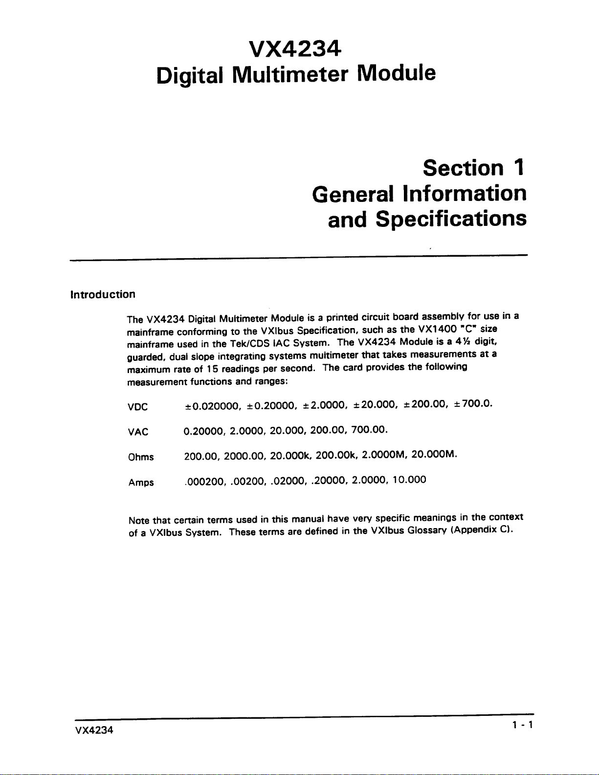
VX4234
Digital Multimeter Module
070-9139-02
This document applies for firmware version 1.00
and above.
Page 2
Page 3
Page 4
Page 5
Page 6

Page 7

General Safety Summary
Review the following safety precautions to avoid injury and prevent damage to
this product or any products connected to it.
Only qualified personnel should perform service procedures.
While using this product, you may need to access other parts of the system. Read
the General Safety Summary in other system manuals for warnings and cautions
related to operating the system.
Injury Precautions
Avoid Electric Overload
Ground the Product
Do Not Operate Without
Covers
Use Proper Fuse
Do Not Operate in
Wet/Damp Conditions
Do Not Operate in
Explosive Atmosphere
Avoid Exposed Circuitry
To avoid electric shock or fire hazard, do not apply a voltage to a terminal that is
outside the range specified for that terminal.
This product is indirectly grounded through the grounding conductor of the
power cord. To avoid electric shock, the grounding conductor must be connected
to earth ground. Before making connections to the input or output terminals of
the product, ensure that the product is properly grounded.
To avoid electric shock or fire hazard, do not operate this product with covers or
panels removed.
To avoid fire hazard, use only the fuse type and rating specified for this product.
To avoid electric shock, do not operate this product in wet or damp conditions.
To avoid injury or fire hazard, do not operate this product in an explosive
atmosphere.
To avoid injury, remove jewelry such as rings, watches, and other metallic
objects. Do not touch exposed connections and components when power is
present.
Product Damage Precautions
Provide Proper Ventilation
VX4234
To prevent product overheating, provide proper ventilation.
iii
Page 8
General Safety Summary
Do Not Operate With
Suspected Failures
If you suspect there is damage to this product, have it inspected by qualified
service personnel.
Safety Terms and Symbols
Terms in This Manual
Terms on the Product
These terms may appear in this manual:
WARNING. Warning statements identify conditions or practices that could result
in injury or loss of life.
CAUTION. Caution statements identify conditions or practices that could result in
damage to this product or other property.
These terms may appear on the product:
DANGER indicates an injury hazard immediately accessible as you read the
marking.
WARNING indicates an injury hazard not immediately accessible as you read the
marking.
CAUTION indicates a hazard to property including the product.
iv
VX4234
Page 9

General Safety Summary
Symbols on the Product
The following symbols may appear on the product:
DANGER
High Voltage
Protective Ground
(Earth) T erminal
ATTENTION
Refer to
Manual
Double
Insulated
VX4234
v
Page 10

Service Safety Summary
Only qualified personnel should perform service procedures. Read this Service
Safety Summary and the General Safety Summary before performing any service
procedures.
Do Not Service Alone
Disconnect Power
Use Care When Servicing
With Power On
Do not perform internal service or adjustments of this product unless another
person capable of rendering first aid and resuscitation is present.
To avoid electric shock, disconnect the main power by means of the power cord
or, if provided, the power switch.
Dangerous voltages or currents may exist in this product. Disconnect power,
remove battery (if applicable), and disconnect test leads before removing
protective panels, soldering, or replacing components.
To avoid electric shock, do not touch exposed connections.
VX4234
vii
Page 11
Page 12
Page 13
Page 14
Page 15
Page 16
Page 17
Page 18
Page 19
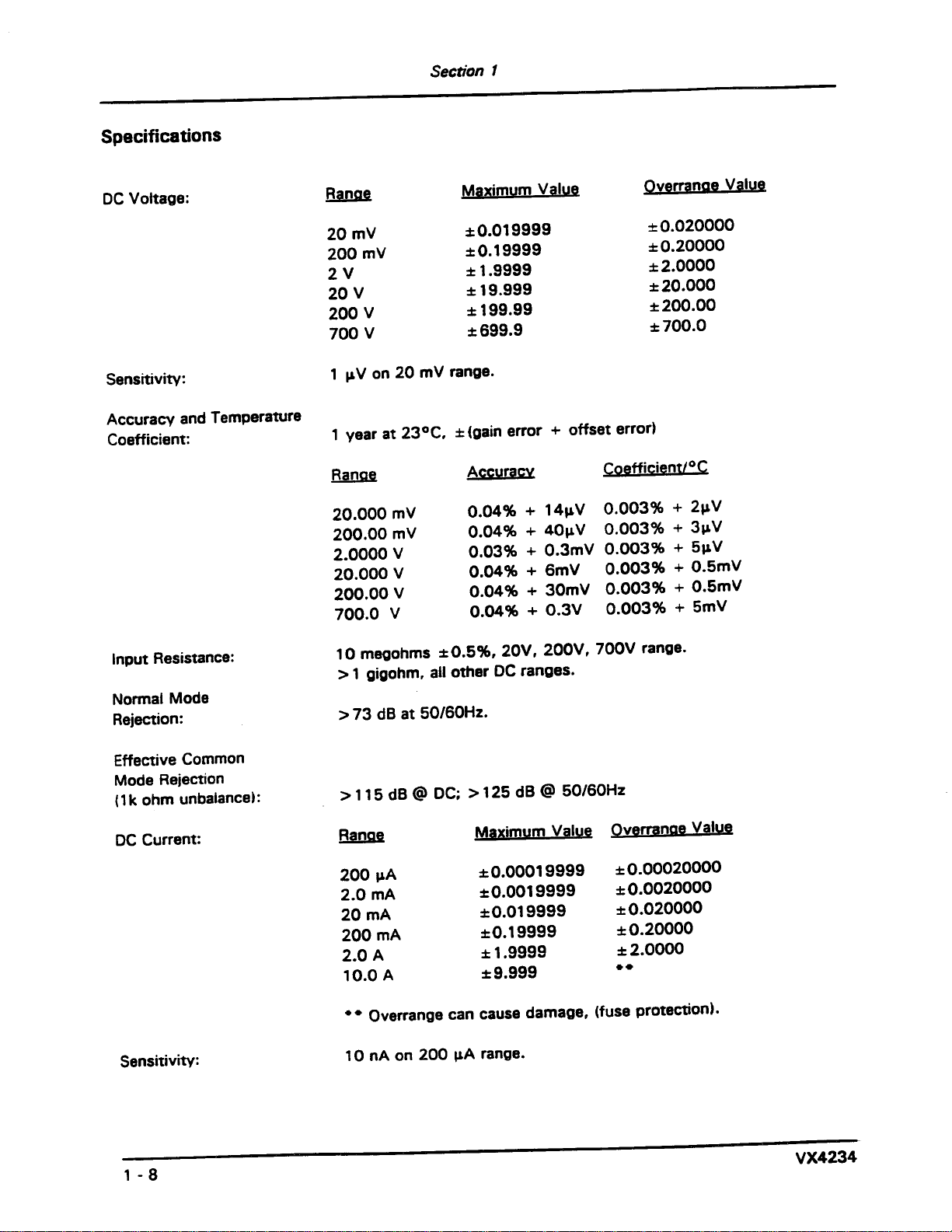
DC Current:
200 A
2.0 mA
20 mA
200 mA
2.0 A
10.0 A
200 mV
2V
20 V
200 V
700 V
N/A
N/A
N/A
N/A
N/A
N/A
Range
15Hz-25Hz
25Hz-50Hz
50 Hz - 7.5 kHz
7.5 kHz - 12 kHz
12 kHz - 20 kHz
15Hz-25Hz
25Hz-50Hz
50 Hz - 7.5 kHz
7.5 kHz - 12 kHz
12 kHz - 20 kHz
15Hz-25Hz
25Hz-50Hz
50 Hz - 7.5 kHz
7.5 kHz - 12 kHz
12 kHz - 20 kHz
15Hz-25Hz
25Hz-50Hz
50 Hz - 7.5 kHz
7.5 kHz - 12 kHz
12 kHz - 20 kHz
15Hz-25Hz
25Hz-50Hz
** with input voltage greater than 10% of full scale.
0.08% + 300 nA
0.08% + 600 nA
0.08% + 6 A
0.12% + 60 A
0.08% + 600 A
0.12%+6mA
Maximum Value Overrange Value
1.25%+1mV
0.8%+1mV
0.6%+1mV
1.0%+1mV
1.5%+1mV
1.25%+6mV
0.8%+6mV
0.6%+6mV
1.0%+6mV
2.0%+6mV
1.25% +80 mV
0.8%+80mV
0.6%+80mV
1.6%+80mV
3.9%+80mV
1.25% + 0.8 V
0.8% + 0.8 V
0.6% + 0.8 V
1.6% + 0.8 V
3.9%+8V
1.25%+8V
0.8% + 0.8 V
0.008% + 30 nA
0.008% + 60 nA
0.013% + 0.6 A
0.033%+6 A
0.013% + 60 A
0.013% + 0.6 mA
0.008% + 9 V
0.008% + 60 V
0.008% + 8 mV**
0.008% + 6 mV**
0.008% + 60 mV**
Page 20
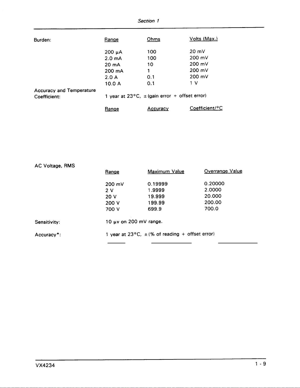
Range
200.00 mV
2.0000 V
20.000 V
200.00 V
700.0 V
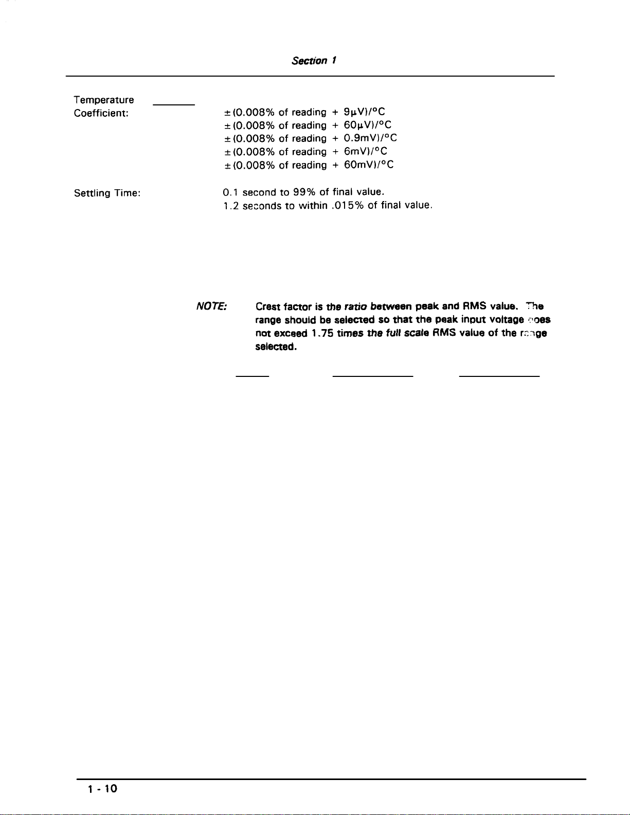
Crest Factor:
AC Current:
2:1 for specified accuracy.
3:1 for additional -0.1% error.
7:1 for additional -1% error.
Range Maximum Value Overrange Value
2mA 15Hz-25Hz
25Hz-50Hz
50 Hz - 7.5 kHz
7.5 kHz - 12 kHz
12 kHz - 20 kHz
20 mA
200 mA
2A
10 A
15Hz-25Hz
25Hz-50Hz
50 Hz - 7.5 kHz
7.5 kHz - 12 kHz
12 kHz - 20 kHz
15Hz-25Hz
25Hz-50Hz
50 Hz - 7.5 kHz
7.5 kHz - 12 kHz
12 kHz - 20 kHz
15Hz-25Hz
25Hz-50Hz
50 Hz - 7.5 kHz
7.5 kHz - 12 kHz
12 kHz - 20 kHz
15Hz-25Hz
25Hz-50Hz
50 Hz - 7.5 kHz
7.5 kHz - 12 kHz
12 kHz - 20 kHz
1.87% + 15 A
1.2% + 15 A
0.9% + 15 A
1.5% + 15 A
2.25% + 15 A
1.87% + 150 A
1.2% + 150 A
0.9% + 150 A
1.5% + 150 A
2.25% + 150 A
1.87% + 1.5 mA
1.2% + 1.5 mA
0.9% + 1.5 mA
1.5% + 1.5 mA
2.25% + 1.5 mA
1.87% + 15 mA
1.2%+15mA
0.9%+15mA
1.5%+15mA
2.25% + 15 mA
1.87% + 90 mA
1.2%+90mA
0.9%+90mA
1.5%+90mA
3.00% + 90 mA
0.015% + 1.5 A
0.02% + 15 A
0.04% + 150 A**
0.02% + 1.5 mA**
0.02% + 9 mA**
VX4234
Page 21
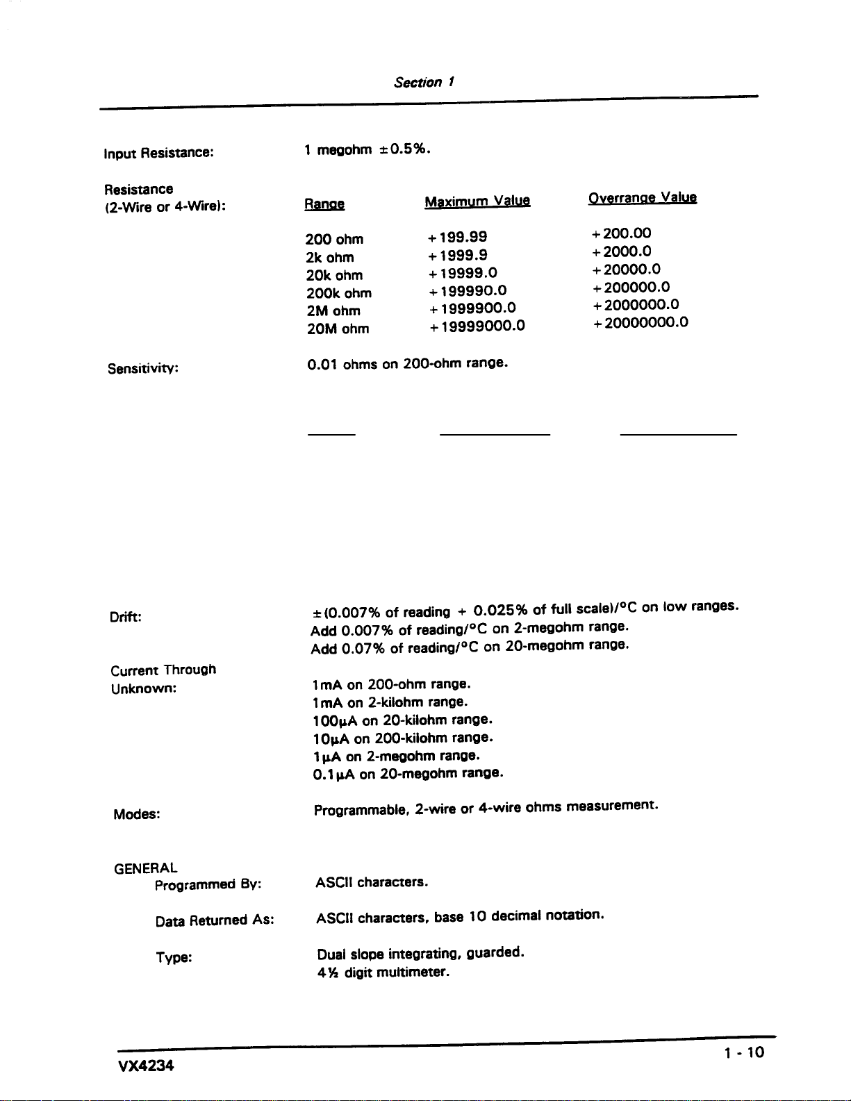
Sensitivity 10 mA on 200 mA range.
Accuracy
(1 year at 23° C):
200 ohm
2 Kohm
20 Kohm
200 Kohm
2 Mohm
20 Mohm
Range Maximum Value Overrange Value
1mA
1mA
100 A
10 A
1 A
0.1 A
0.14% + 0.03 ohm
0.08% + 0.3 ohm
0.08%+3ohm
0.08% + 30 ohm
0.14% + 300 ohm
0.98% + 3000 ohm
not specified
not specified
not specified
not specified
not specified
not specified
A
Page 22
Page 23
Page 24

Page 25

Page 26
Page 27
Page 28

Page 29

Page 30

Page 31

Page 32

Page 33

Page 34

Page 35

Page 36

Page 37

Page 38

Page 39

Page 40

Page 41

Page 42

Page 43

Page 44

Page 45

Page 46

Page 47

Page 48

Page 49

Page 50

Page 51

Page 52

Page 53

Page 54

Page 55

Page 56

Page 57

Page 58

Page 59

Page 60

Page 61

Page 62

Page 63

Page 64

Page 65

Page 66

Page 67

Page 68

Page 69

Page 70

Page 71

Page 72

Appendix F: Performance Verification
This Performance Verification contains test sequences suitable for determining if
the VX4234 is functioning properly and meets the characteristics as warranted.
The following skills are required to perform this procedure:
Thorough knowledge of test instrument operation and proper measurement
techniques
Knowledge of VXIbus system components and command language
programming
Ability and facility to construct interconnections and fixtures as needed to
perform the procedure
General Information and Conventions
The following conventions apply throughout this procedure:
Each test sequence begins with a table, similar to the one below, which
provides information and requirements specific to that section. The item
number appearing after each piece of equipment refers to an entry in Table 1,
Required Test Equipment. Following the table, you will be given instructions
for interconnecting the VX4234 under-test and for checking the performance
parameters. Results may be recorded on a photocopy of the Test Record on
page A–24.
VX4234
Equipment
Requirements
Prerequisites All prerequisites listed on page A–22
This procedure assumes that you will be using a VX4521 Slot 0 Resource
Manager and a National Instruments PC-GPIB controller configuration as
described in Table 3. If you are using a different controller and software,
simply substitute the commands for that system to achieve the equivalent
results. In the test sequences, you will be instructed to issue Interface Bus
Interactive Control (ibic) commands to set up the VX4234 under-test and
other associated VXIbus test instruments. Please refer to the NI-488.2M
User Manual for additional information.
Commands to the VX4234 may be entered in upper or lower case. To avoid
confusion between alphanumeric characters, for example between a one (1)
Calibrator-Generator (item 1)
Coaxial Cable (item 2)
Dual Banana Connector, two (item 3)
A–21
Page 73

Appendix F: Performance Verification
Prerequisites
The verification sequences in this procedure are valid under the following
conditions:
The VX4234 module covers are in place and the module is installed in an
The VX4234 has passed the power-on self test
The VX4234 has been operating for a warm-up period of 10 minutes in an
and an “L” or a zero (0) and and the letter “o”, all commands in this
procedure are illustrated in the case which provides the greatest visual
distinction. However, when entering these commands you may use any
combination of upper and/or lower case.
approved VXIbus mainframe as described in Section 2 of the User Manual
ambient environment as specified in Section 1 of the User Manual
Equipment Required
This procedure uses traceable test equipment as specified in Table 1 to directly
check warranted characteristics. You may use instrumentation other than the
recommended example if it meets the minimum requirements.
T able 1: Required Test Equipment
Item Number and Description Minimum Requirements Example Purpose
1. Calibrator-Generator Variable DC Voltage to ± 700 V DC,
accuracy to 0.005%
Variable DC Current to 2.0 Amps,
accuracy to 0.005%
Variable True RMS to 700 V AC, 50 Hz
to 7500 Hz; accuracy to 0.005%
Variable Resistance to 10 M ,
accuracy to 0.005%
2. Coaxial BNC Cable
(two required)
3. Adapter, BNC female to dual
banana (four required)
4. 1 k , Resistor 1 k , Watt, 5% Tektronix part number
50 , 36 inch, male to male BNC
connectors
50 , BNC female to dual banana Tektronix part number
Fluke 5700A Calibrator Checking AC & DC Voltage,
DC Amps, and Resistance
accuracy .
Tektronix part number
012-0482-00
103-0090-00
315-0102-00
Interconnecting electrical
signals
Interconnecting electrical
signals
Checking CMRR
A–22
VX4234
Page 74

T able 1: Required Test Equipment (Cont.)
Item Number and Description PurposeExampleMinimum Requirements
Appendix F: Performance Verification
5. Adapter, BNC male to Dual
Binding post
6. Adapter, BNC female to
Clip Leads
50 , BNC male to Dual Binding post Tektronix part number
103-0035-00
50 , BNC female to dual Clip Leads Tektronix part number
013-0076-00
Interconnecting electrical
signals
Interconnecting electrical
signals
VX4234 Under-Test Configuration
The VX4234 under-test must be installed in an approved VXIbus system. At a
minimum, the system must contain the elements listed in Table 2.
T able 2: Elements of a Minimum VX4234 Under-Test System
Item Number and Description Minimum Requirements Example Purpose
1. VXIbus Mainframe One available slot (in addition to
the Slot 0 Resource Manager) for
the VX4234 under-test
2. Slot 0 Resource Manager Resource Mgr., Slot 0 Functions,
IEEE 488 GPIB Interface
3. VXIbus System Controller VXIbus-Talker/Listener/Controller 486 PC with National GPIB
Tektronix VX1410 IntelliFrame Provides power, cooling, and
backplane for VXIbus modules
VX4521 Slot 0 Resource Mgr. Provides Slot 0 Resource Mgr.
functions, and GPIB interface
Provides VXIbus command
PC2A & NI-488.2M software,
GPIB cable
and response interface
Test System Configuration
Test Record
VX4234
Table 3 describes the VXIbus system configuration assumed in this procedure. If
your configuration is different, please note that you will observe your device
names and addresses in test sequences. No secondary addressing is assumed.
Table 3: Test System Configuration Assumed
GPIB Device
Device
GPIB0 GPIB0 (PC card) NA 30
VX4521 VX4521 Slot 0 0D (hex) 13
VX4234 under-test VX4234 Slot 1 01 1
Name
VXI Slot
VXIbus Logical
Address
GPIB Primary
Address
Photocopy the Test Record which follows to record your results.
A–23
Page 75

Appendix F: Performance Verification
stem Configuration Response
T able 4: VX4234 Test Record
VX4234 Serial Number: Temperature and Relative Humidity:
Date of Last Calibration: Verification Performed by:
Certificate Number: Date of Verification:
VXIbus Interface Logical Address, IEEE Address, Slot No., MFG., Model, etc.
Sy
Extended Self Test Verification (S1) Passed Failed
DC Voltage Accuracy
20 mV Range ( R1 )
( 0.04% + 14 uV )
Calibrator +18.0000 mV +0.00000 mV –18.0000 mV
200 mV Range ( R2 )
( 0.04% + 40 uV )
2.0 V Range ( R3 )
( 0.03% + 0.3 mV )
20.0 V Range ( R4 )
( 0.04% + 6.0 mV )
Max. +.018021 . . +.000014 –.017979 . .
Measure
Min. +.017979 . . –.000014 –.018021 . .
Calibrator +180.000 mV +0.0000 mV –180.000 V
Max. +.18011 . . +.00004 . . –.17989 . .
Measure
Min. +.17989 . . –.00004 . . –.18011 . .
Calibrator +1.80000 V +0.0000 mV –1.80000 V
Max. +1.8008 . . +.0003 . . –1.7992 . .
Measure
Min. +1.7992 . . –.0003 . . –1.8008 . .
Calibrator +18.0000 V +0.0000 mV –18.0000 V
Max. +18.013 . . +.006 . . –17.987 . .
Measure
Min. +17.987 . . –.006 . . –18.013 . .
A–24
VX4234
Page 76

T able 4: VX4234 Test Record (Cont.)
Common Mode Rejectio
DC Voltage Accuracy
200.0 V Range ( R5 )
( 0.04% + 30 mV )
700.0 V Range ( R6 )
( 0.04% + 0.3 mV )
Normal Mode Rejection ≤ 73 dB @ 50/60 Hz
n ≤ 115 dB @ DC
Calibrator +180.000 V +0.0000 mV –180.000 V
Max. +180.10 . . +.03 . . –179.90 . .
Measure
Min. +179.90 . . –.03 . . –180.10 . .
Calibrator +630.000 V +0.0000 mV –630.000 V
Max. +630.3 . . +.0 . . –629.7 . .
Measure
Min. +629.7 . . –.0 . . –630.3 . .
Appendix F: Performance Verification
(1 kW unbalance)
DC Current Accuracy
200 mA Range ( R1 )
( 0.04% + 14 mA )
2.0 mA Range ( R2 )
( 0.04% + 40 mA )
20 mA Range ( R3 )
( 0.04% + 40 mA )
≤ 125 dB @ 50/60 Hz
Calibrator +180.000 mA +10.000 mA –180.000 mA
Max. +.00019407 . . +.00002400 –.00016592 . .
Measure
Min. +.00016592 . . –.00000400 –.00019407 . .
Calibrator +1.80000 mA +10.000 mA –1.80000 mA
Max. +.0018407 . . +.0000500 . . –.0017593 . .
Measure
Min. +.0017593 . . –.0000300 . . –.0018407 . .
Calibrator +18.0000 mA +10.000 mA –18.0000 mA
Max. +.018407 . . +.000050 . . –.017953 . .
Measure
Min. +.017953 . . –.000030 . . –.018407 . .
200 mA Range ( R4 )
( 0.04% + 40 mA )
VX4234
Calibrator +180.000 mA +10.000 mA –180.000 mA
Max. +.18011 . . +.00005 . . –.17989 . .
Measure
A–25
Page 77

Appendix F: Performance Verification
T able 4: VX4234 Test Record (Cont.)
DC Current Accuracy
Min. +.17989 . . –.00003 . . –.18011 . .
2.0 A Range ( R5 )
( 0.04% + 40 mA )
10.0 A Range ( R6 )
( 0.04% + 0.3 mA )
Calibrator +1.8000 A +10.000 mA –180.000 A
Max. +1.8008 . . +.0000 . . –1.8000 . .
Measure
Min. +1.8000 . . –.0000 . . –1.8008 . .
Calibrator +1.90000 A +10.000 mA –1.90000
Max. +1.901 . . +.000 . . –1.899 . .
Measure
Min. +1.899 . . –.000 . . –1.901 . .
AC RMS Voltage Accuracy Calibrator Maximum Measure Minimum
200 mV Range ( R2 )
( 0.6% + 1 mV )
2.0 V Range ( R3 )
( 0.6% + 6 mV )
20.0 V Range ( R4 )
( 0.6% + 80 mV )
200.0 V Range ( R5 )
( 0.6% + 30 mV )
700.0 V Range ( R6 )
( 0.6% + 8.0 V )
Resistance Accuracy Calibrator Maximum Measure Minimum
200 W Range (R1)
±( 0.14% Value + 0.015% FS)
2 kW Range (R1)
±( 0.08% Value + 0.015% FS
20 kW Range (R1)
±( 0.08% Value + 0.015% FS
200 kW Range (R1)
±( 0.08% Value + 0.015% FS
+180.000 mV (6 kHz) +.18208 . . +.17792 . .
+1.80000 V (6 kHz) +1.8168 . . +1.7832 . .
+18.0000 V (6 kHz) +18.188 . . +17.812 . .
+180.000 V (6 kHz) +181.88 . . +178.12 . .
+630.000 V (6 kHz) +641.8 . . +618.2 . .
100.000 +100.17 . . +99.83 . .
1000.00 +1001.1 . . +998.9 . .
10.0000 k +10011.0 . . +9989.0 . .
100.000 k +100110.0 . . +99890.0 . .
2 MW Range (R1)
±( 0.14% Value + 0.015% FS
20 MW Range (R1)
±( 0.17% Value + 0.015% FS
A–26
1.00000 M +1001700.0 . . +998300.0 . .
10.0000 M +10020000.0 . . +9980000.0 . .
VX4234
Page 78

Self Test
Appendix F: Performance Verification
The VX4234 includes a built-in self test function (BITE) which runs automatically each time the power is turned on and when the internal self-tests (V0 and
V1) are executed.
BITE uses internal routines and reference circuitry to confirm the instrument’s
capability to measure voltage, current, and resistance, and convert the measurement to a digital result. You may additionally execute the extended AC and DC
mid–scale tests with the V1 command.
NOTE. Because these tests verify operation up to the front panel, you must
disconnect all input signals before executing the extended verification.
In addition to BITE, the front panel indicator lights display the current status of
module power, module self test results (including the central processor), and the
assertion of SYSFAIL*. If the module loses any of its power voltages, the Failed
light will be on, the Power light will be off, and SYSFAIL* will be asserted.
Following a successful VXIbus system startup sequence, the green PWR light on
the VX4234 front panel indicates that the self test has passed and that the +5 V
power supply is operational.
NOTE. If you experience an error indication from the VX4234-under-test, or any
other VXIbus module, investigate and correct the problem before proceeding.
Common items to check are logical address conflicts (primary and secondary;
see Table 3), breaks in the VXIbus daisy chain signals, improper seating of a
module, loose GPIB cable, or loose or blown fuses.
Performance Verification Tests
This Performance Verification procedure may be executed in any order. You may
use any VXIbus system which meets the requirements described in Table 2,
however, the test sequences are structured for a system configuration as
described in Table 3.
NOTE. If at any time you do not observe the expected result, check the front panel
ERROR light. If it is on, perform error Queries (ibwrt ”e”<cr> ibrd 100<cr>)
until you receive a response of “99 . .”. Following a response of “99 . .”, the
front panel ERROR light should be off.
VX4234
A–27
Page 79

Appendix F: Performance Verification
VXIbus Interface
This sequence verifies that the VX4234 configures correctly and
communicates
properly with your system controller. It assumes a VXIbus system configuration
as specified in Table 3, and in particular, utilizes the VX4521 Resource Manager
“table” command for verification of the system configuration. If your VXIbus
system uses a different Resource Manager, you must substitute commands
specific to that Resource Manager-Controller to verify your system configuration.
Equipment
Requirements
Prerequisites All prerequisites listed on Page A–22
No test equipment required.
1. If you are using the VX4521 Slot 0 Resource Manager, send the TABLE
command to verify the system configuration. (If you are using a different
Controller, perform the equivalent function to confirm the responses shown
in Table 5.) Your configuration may not be identical, but the information
should be the same.
T able 5: VXIbus System Configuration
Command to Type Response to Verify
ibic
buffer 1
(Allows more comfortable viewing of responses)
ibfind VX4521
ibwrt "table"
ibrd 200 02 (Implies two modules in this system)
! LA 0, IEEE 13, Slot 0, MFG FFDh, MODEL VX4521,
PASS, , RM..
! LA 1, IEEE 01, Slot 1, MFG FFCh, MODEL VX4234,
PASS TRIGGER;LOCK;READ STB, MESG, 0, V1.3,
NORMAL ..
2. To verify overall module functionality, send the extended self-test (verifica-
tion) command and an Error query. Then confirm that the front panel
ERROR light is off and that there are no errors (code 99 indicates no errors).
ibfind VX4234
ibwrt "V1E" (Observe that the ERROR light is off)
and the tables and figures are thru numbered Arabic. ibrd 100
(Observe a response of: 99 . .)
A–28
VX4234
Page 80

Appendix F: Performance Verification
DC Voltage Accuracy
This sequence verifies the accuracy of the six DC voltage ranges.
Equipment
Requirements
Prerequisites All prerequisites listed on page A–22
Calibrator (item 1)
Coaxial Cable, one (item 2)
Dual Banana Connectors, two (item 3)
1. Set the Calibrator to +0.0000 mV DC .
2. Connect the Calibrator to the VX4234 Voltage Input using two Dual-Banana
connectors and a Coaxial cable.
3. Set the Calibrator to +18.0 mV DC.
4. With the following commands, set the VX4234 to DC volts and for the
20 mV range (Function 1, Range 1). Then perform an acquisition and verify
the response relative to the limits shown in the Test Record.
set VX4234
ibwrt "F1R1"
ibrd 100 (Observe: +.01800 ±0.0000212 VDC, see Table 6)
5. Set the Calibrator to –18.0 mV DC.
6. Re-acquire and verify the response to the limits shown in the Test Record:
ibrd 100 (Observe: –.01800 ±0.0000212 VDC, see Table 6)
7. Check the additional voltages listed in Table 6 . (Note that the first entry in
Table 6 is a repeat of steps 4 through 6 above .)
Table 6: DC Voltage Accuracy
Set Calibrator
+18.0000 mV DC
–18.0000 mV DC
(Steps 3 to 6 repeated for table
continuity)
+180.000 mV DC
–180.000 mV DC
+1.80000 VDC
–1.80000 VDC
Command To VX4234
ibwrt "F1R1"
ibrd 100
ibrd 100
ibwrt "R2"
ibrd 100
ibrd 100
ibwrt "R3"
ibrd 100
ibrd 100
Response to Verify
+.018021 . . to +.017979 . .
–.017979 . . to –.018021 . .
+.18011 . . to +.17989 . .
–.17989 . . to –.18011 . .
+1.8008 . . to +1.7992 . .
–1.7992 . . to –1.8008 . .
VX4234
A–29
Page 81

Appendix F: Performance Verification
Table 6: DC Voltage Accuracy (Cont.)
DC Common Mode
Rejection
Set Calibrator Response to Verify
+18.0000 VDC
Command To
ibwrt "R4"
ibrd 100
–18.0000 VDC
+180.000 VDC
ibrd 100
ibwrt "R5"
ibrd 100
–180.000 VDC
+630.00 VDC
ibrd 100
ibwrt "R6"
ibrd 100
–630.00 VDC
ibrd 100
VX4234
+18.013 . . to + 17.987 . .
–17.987 . . to –18.013 . .
+180.10 . . to +179.90 . .
–179.90 . . to –180.10 . .
+630.3 . . to +629.7 . .
–629.7 . . to –630.3 . .
8. Set the Calibrator to +0.0000 mV.
This sequence verifies the capability of the VX4234 to reject Common Mode
voltage when operating in the DC Voltage measurement mode.
Equipment
Requirements
Calibrator (item 1)
Coaxial Cable, one (item 2)
Dual Banana Connectors, two (item 3)
Binding Post Connector (item 5)
Clip Lead Connector (item 6)
1 k Resistor ( ¼ Watt, 5%)
A–30
Prerequisites All prerequisites listed on page A–22
1. Set the Calibrator to +0.0000 mV DC.
2. Connect the Calibrator to the VX4234 as follows:
a. Connect a BNC to Dual Banana connector to the Voltage input of the
VX4234.
b. Connect a BNC to Dual Binding post connector to the BNC to Dual
Banana connector on the VX4234.
c. Connect a 1 k resistor between the binding posts.
d. Connect a BNC to Dual Banana adapter to the calibrator then connect
one end of a coaxial cable to the Dual Banana adapter and the opposite
end of the coaxial cable to a BNC to Clip Lead adapter.
VX4234
Page 82

Appendix F: Performance Verification
e. Connect the red lead of the Clip Lead adapter to the red Dual Binding
post adapter on the VX4234 (one side of the resistor).
f. Connect the black lead of the Clip Lead adapter to the Chassis Ground
binding post of the VX4234.
3. Set the Calibrator to +100.0 VDC, and enable the output.
4. Using the following commands, set the VX4234 to read DC volts on the
20 mV range (Function 1, Range 1). Perform two acquisitions and verify the
second response to be ≤ 177.8 mV (Note: The first reading returned is stale
data).
set VX4234
ibwrt "F1R1"
ibrd 100 (Disregard this reading.)
ibrd 100 (Observe: ≤ [+/-].000018 . .)
DC Normal Mode
Rejection
5. Set the Calibrator to +100.0 V, 50 or 60 Hz. Perform two acquisitions and
verify the second response to be ≤ 56.8 mV
ibrd 100 (Disregard this reading.)
ibrd 100 (Observe: 3 [+/–].000056 . .)
6. Set the Calibrator to +0.0000 mV DC.
This sequence verifies the ability of the VX4234 to reject residual AC voltage
present on the input when operating in a DC Voltage mode.
Equipment
Requirements
Prerequisites All prerequisites listed on page A–22
Calibrator (item 1)
Coaxial Cable, one (item 2)
Dual Banana Connectors, two (item 3)
1. Set the Calibrator to +0.0000 mV DC.
2. Verify the VX4234-under-test 50/60 Hz reject switch (side panel) is in the
60 Hz position.
VX4234
3. Connect the Calibrator to the VX4234 Voltage Input using two Dual-Banana
connectors and a Coaxial cable.
4. Set the Calibrator to +10.0 V, 60 Hz and enable the output.
A–31
Page 83

Appendix F: Performance Verification
5. Using the following commands, set the VX4234 to read DC volts on the
6. Power down the VXI system, remove the VX4234-under-test and set the
7. Set the Calibrator to +10.0 V, 50 Hz.
8. Perform two acquisitions and verify the second response to be ≤ 2.24 mV.
20 mV range (Function 1, Range 1). Perform two acquisitions and verify the
second response to be ≤ 2.24 mV (Note: The first reading returned is stale
data).
set VX4234
ibwrt "F1R1"
ibrd 100 (Disregard this reading.)
ibrd 100 (Observe: 3 [+/–].002239 . .)
50/60 Hz reject switch to the 50 Hz position. Reinstall the VX4234
under-test and power-on the system.
DC Current Accuracy
ibrd 100 (Disregard this reading.)
ibrd 100 (Observe: 3 [+/–].002239 . .)
9. Set the Calibrator to +0.0000 mV DC.
10. Reset the VX4234-under-test 60 Hz reject switch to the AC power source
frequency being used by the VXI system.
This sequence verifies the accuracy of the six DC Current ranges.
Equipment
Requirements
Prerequisites All prerequisites listed on page A–22
Calibrator (item 1)
Coaxial Cable, one (item 2)
Dual Banana Connector, two (item 3)
1. Set the Calibrator to +0.0000 mV (If using the Fluke 5700A, press the clear
button twice).
2. Connect the Calibrator to the VX4234 Voltage input using two Dual-Banana
connectors and a Coaxial cable.
A–32
VX4234
Page 84

Appendix F: Performance Verification
3. Set the VX4234 to DC Current on the 200 mA range (Function 6. Range 1) .
set VX4234
ibwrt "F6R1"
4. Set the Calibrator to +180.000 mA.
5. Acquire a reading from the VX4234 and verify the response relative to the
limits shown in the Test Record (limits also shown in Table 7 and 8):
ibrd 100 (Observe; +.00018000 ±0.00001407A {table 7})
6. Set the Calibrator to –180.000 mA.
7. Acquire a reading from the VX4234 and verify the response to the limits
shown in the Test Record:
ibrd 100 (Observe: –.00018000 ±0.00001407 A {table 7})
8. Check the additional currents listed in Table 7 and 8. (Note that the first
entry in Table 7 is a repeat of steps 3 through 7 above.)
T able 7: DC Current Accuracy
Set Calibrator
+180.000 mA
–180.000 mA
Command to VX4234
ibwrt "F6R1"
ibrd 100
ibrd 100
Response to Verify
+.00019407 to +.00016593
–.00016593 to –.00019407
(Steps 3 to 7 repeated for
continuity)
+1.80000 mA
–1.80000 mA
+18.0000 mA
–18.0000 mA
+180.000 mA
–180.000 mA
ibwrt "R2"
ibrd 100
ibrd 100
ibwrt "R3"
ibrd 100
ibrd 100
ibwrt "R4"
ibrd 100
ibrd 100
+.0018407 to +.0017593
–.0017593 to –.0018407
+.018047 . . to +.017953 . .
–.017953 . . to –.018047 . .
+.18011 . . to + .17989 . .
–.17989 . . to –.18011 . .
9. Remove the Calibrator signal from the VX4234 “200 mA max” input and
connect to the “10 A max” input. Continue the DC Current checks as
directed in Table 8. (Be careful to reconnect the Calibrator cable in the
proper polarity. This will require rotating the dual banana connector 180
degrees.)
VX4234
A–33
Page 85

Appendix F: Performance Verification
T able 8: High Range DC Current Accuracy
AC Voltage Accuracy
Set Calibrator
+1.80000 A
–1.80000 A
+1.90000 A
–1.90000 A
Command to VX4234
ibwrt "R5"
ibrd 100
ibrd 100
ibwrt "R6"
ibrd 100
ibrd 100
Response to Verify
+1.8008 . . to +1.7992 . .
–1.7992 . . to –1.8008 . .
+1.901 . . to +1.899 . .
–1.899 . . to –1.901 . .
10. Set the Calibrator to +0.0000 mV.
This sequence verifies the accuracy of the five AC RMS voltage ranges.
Equipment
Requirements
Prerequisites All prerequisites listed on page A–22
Calibrator (item 1)
Dual Banana Connectors, two (item 3)
Coaxial cable, one (item 2)
1. Set the Calibrator to 180.000 mV and 6.0 kHz.
2. Connect the Calibrator to the VX4234 Voltage input using two Dual-Banana
connectors and a Coaxial cable.
3. Set the VX4234 to AC volts and the 200 mV range (Function 5, Range 2).
(Note: There is no Range 1 for AC). Acquire a reading from the VX4234 and
verify the response relative to the limits shown in the Test Record (limits are
also shown in Table 9):
set VX4234
ibwrt "F5R2" (Note: there is no R1 range for AC Volts)
ibrd 100 (Observe: +.18000 ±.00208, see Table 9)
4. Check the additional voltages as directed in Table 9 . (Note that the first
entry in Table 9 is a repeat of step 3 above.)
A–34
VX4234
Page 86

Table 9: AC RMS Voltage Accuracy
Appendix F: Performance Verification
Resistance Accuracy
Set Calibrator
+180.000 mV, 6.0 kHz
(Step 3 above repeated for
table continuity.)
+1.80000 V, 6.0 kHz
+18.0000 V, 6.0 kHz
+180.000 V, 6.0 kHz
+630.00 V , 1.0 kHz
Command to VX4234
ibwrt "F5R2"
ibrd 100
ibwrt "R3"
ibrd 100
ibwrt "R4"
ibrd 100
ibwrt "R5"
ibrd 100
ibwrt "R6"
ibrd 100
Response to Verify
+.18208 . . to +.17792 . .
+1.8168 . . to +1.7832 . .
+18.188 . . to + 17.812 . .
+181.88 . . to +178.12 . .
+641.8 . . to +618.2 . .
5. Set the Calibrator to +0.0000 mV DC.
This sequence verifies the accuracy of the six (6) Resistance ranges.
Equipment
Requirements
Calibrator (item 1)
Coaxial Cable, two (item 2)
Dual Banana Connectors, four (item 3)
Prerequisites All prerequisites listed on page A–22
1. Set the Calibrator to 100 .
2. Connect the Calibrator Hi/Lo Output to the top input (R+/R-) of the
VX4234 using two Dual-Banana connectors and a Coaxial cable.
3. Connect the Calibrator Hi/Lo Sense to the bottom input (R+/R-) of the
VX4234 using a second Coaxial cable and two Dual-Banana connectors.
4. Set the VX4234 to 4-Wire and the 200 range (Function 4, Range 1).
Acquire a reading from the VX4234 and verify the response relative to the
limits shown in the Test Record (the limits are also shown in Table 9):
set VX4234
ibwrt "F4R1"
ibrd 100 (Observe: +100.00 +0.170W, see Table 10)
VX4234
A–35
Page 87

Appendix F: Performance Verification
5. Check the additional resistance ranges listed in Table 10. (Note that the first
T able 10: Resistance Accuracy
Set Calibrator Command to VX4234 Response to Verify
+100.000
(Step 4 repeated for continuity)
+1000.00
+10.0000 k
+100.000 k
+1.00000 M
+10.0000 M
entry in Table 10 is a repeat of steps 4 above.)
ibwrt "F4R1"
ibrd 100
ibwrt "R2"
ibrd 100
ibwrt "R3"
ibrd 100
ibwrt "R4"
ibrd 100
ibwrt "R5"
ibrd 100
ibwrt "R6"
ibrd 100
+100.17 . . to +99.83 . .
+1001.1 . . to +998.9 . .
+10011.0 . . to +9989.0 . .
+100110.0 . . to + 99890.0 . .
+1001700.0 to +998300.0 . .
+10020000.0 to +9980000.0
This completes the VX4234 verification procedure.
A–36
VX4234
Page 88

WARNING
The following servicing instructions are for use only by qualified personnel. To
avoid injury, do not perform any servicing other than that stated in the operating
instructions unless you are qualified to do so. Refer to all Safety Summaries before
performing any service.
Page 89

37
Page 90

Appendix G
38
Page 91

Appendix G
39
Page 92

Appendix G
40
 Loading...