

Page 1

User Manual
VX4101A
MultiPaqInstrument
071-0049-01
This document supports firmware version 2.0
Warning
The servicing instructions are for use by qualified
personnel only. To avoid personal injury, do not
perform any servicing unless you are qualified to
do so. Refer to the Safety Summary prior to
performing service.
Page 2

Copyright T ektronix, Inc. All rights reserved. Licensed software products are owned by Tektronix or its suppliers and
are protected by United States copyright laws and international treaty provisions.
Use, duplication, or disclosure by the Government is subject to restrictions as set forth in subparagraph (c)(1)(ii) of the
Rights in T echnical Data and Computer Software clause at DFARS 252.227-7013, or subparagraphs (c)(1) and (2) of the
Commercial Computer Software – Restricted Rights clause at F AR 52.227-19, as applicable.
T ektronix products are covered by U.S. and foreign patents, issued and pending. Information in this publication supercedes
that in all previously published material. Specifications and price change privileges reserved.
Printed in the U.S.A.
T ektronix, Inc., P.O. Box 1000, Wilsonville, OR 97070–1000
TEKTRONIX and TEK are registered trademarks of T ektronix, Inc.
Page 3

WARRANTY
T ektronix warrants that this product will be free from defects in materials and workmanship for a period of three (3) years
from the date of shipment. If any such product proves defective during this warranty period, T ektronix, at its option, either
will repair the defective product without charge for parts and labor, or will provide a replacement in exchange for the
defective product.
In order to obtain service under this warranty, Customer must notify Tektronix of the defect before the expiration of the
warranty period and make suitable arrangements for the performance of service. Customer shall be responsible for
packaging and shipping the defective product to the service center designated by T ektronix, with shipping charges prepaid.
T ektronix shall pay for the return of the product to Customer if the shipment is to a location within the country in which the
T ektronix service center is located. Customer shall be responsible for paying all shipping charges, duties, taxes, and any
other charges for products returned to any other locations.
This warranty shall not apply to any defect, failure or damage caused by improper use or improper or inadequate
maintenance and care. T ektronix shall not be obligated to furnish service under this warranty a) to repair damage resulting
from attempts by personnel other than T ektronix representatives to install, repair or service the product; b) to repair
damage resulting from improper use or connection to incompatible equipment; or c) to service a product that has been
modified or integrated with other products when the effect of such modification or integration increases the time or
difficulty of servicing the product.
THIS WARRANTY IS GIVEN BY TEKTRONIX WITH RESPECT TO THIS PRODUCT IN LIEU OF ANY
OTHER WARRANTIES, EXPRESSED OR IMPLIED. TEKTRONIX AND ITS VENDORS DISCLAIM ANY
IMPLIED WARRANTIES OF MERCHANTABILITY OR FITNESS FOR A PARTICULAR PURPOSE.
TEKTRONIX’ RESPONSIBILITY TO REPAIR OR REPLACE DEFECTIVE PRODUCTS IS THE SOLE AND
EXCLUSIVE REMEDY PROVIDED TO THE CUST OMER FOR BREACH OF THIS WARRANTY. TEKTRONIX
AND ITS VENDORS WILL NOT BE LIABLE FOR ANY INDIRECT , SPECIAL, INCIDENTAL, OR
CONSEQUENTIAL DAMAGES IRRESPECTIVE OF WHETHER TEKTRONIX OR THE VENDOR HAS
ADVANCE NOTICE OF THE POSSIBILITY OF SUCH DAMAGES.
Page 4

Page 5

Table of Contents
Getting Started
General Safety Summary xi. . . . . . . . . . . . . . . . . . . . . . . . . . . . . . . . . . . .
Service Safety Summary xiii. . . . . . . . . . . . . . . . . . . . . . . . . . . . . . . . . . . . .
Preface xv. . . . . . . . . . . . . . . . . . . . . . . . . . . . . . . . . . . . . . . . . . . . . . . . . . .
Product Description 1–1. . . . . . . . . . . . . . . . . . . . . . . . . . . . . . . . . . . . . . . . .
VX4101A Description 1–1. . . . . . . . . . . . . . . . . . . . . . . . . . . . . . . . . . . . . . . . . . . . .
Power-On Sequence 1–7. . . . . . . . . . . . . . . . . . . . . . . . . . . . . . . . . . . . . . . . . . . . . . .
Physical Description 1–7. . . . . . . . . . . . . . . . . . . . . . . . . . . . . . . . . . . . . . . . . . . . . . .
Fuses 1–10. . . . . . . . . . . . . . . . . . . . . . . . . . . . . . . . . . . . . . . . . . . . . . . . . . . . . . . . . . .
IEEE-488 Address 1–10. . . . . . . . . . . . . . . . . . . . . . . . . . . . . . . . . . . . . . . . . . . . . . . .
Self-Test 1–10. . . . . . . . . . . . . . . . . . . . . . . . . . . . . . . . . . . . . . . . . . . . . . . . . . . . . . . .
Accessories 1–12. . . . . . . . . . . . . . . . . . . . . . . . . . . . . . . . . . . . . . . . . . . . . . . . . . . . . .
Performance Options 1–13. . . . . . . . . . . . . . . . . . . . . . . . . . . . . . . . . . . . . . . . . . . . . .
About the VXIplug&play Software 1–13. . . . . . . . . . . . . . . . . . . . . . . . . . . . . . . . . . .
Installation 1–15. . . . . . . . . . . . . . . . . . . . . . . . . . . . . . . . . . . . . . . . . . . . . . . .
Installing the Module in the Mainframe 1–15. . . . . . . . . . . . . . . . . . . . . . . . . . . . . . . .
Installing the VXIplug&play Software 1–17. . . . . . . . . . . . . . . . . . . . . . . . . . . . . . . .
Powering-On the VX4101A 1–22. . . . . . . . . . . . . . . . . . . . . . . . . . . . . . . . . . . . . . . . .
SYSFAIL* Operation 1–25. . . . . . . . . . . . . . . . . . . . . . . . . . . . . . . . . . . . . . . . . . . . . .
Functional Check 1–25. . . . . . . . . . . . . . . . . . . . . . . . . . . . . . . . . . . . . . . . . . . . . . . . .
Operational Check 1–26. . . . . . . . . . . . . . . . . . . . . . . . . . . . . . . . . . . . . . . . . . . . . . . .
Installation Checklist 1–30. . . . . . . . . . . . . . . . . . . . . . . . . . . . . . . . . . . . . . . . . . . . . .
Operating Basics
About Global and Instrument Commands 2–1. . . . . . . . . . . . . . . . . . . . . .
About Global Commands 2–1. . . . . . . . . . . . . . . . . . . . . . . . . . . . . . . . . . . . . . . . . . .
About Instrument Commands 2–1. . . . . . . . . . . . . . . . . . . . . . . . . . . . . . . . . . . . . . .
VX4101A Operational Modes 2–3. . . . . . . . . . . . . . . . . . . . . . . . . . . . . . . .
About Synchronous Mode 2–3. . . . . . . . . . . . . . . . . . . . . . . . . . . . . . . . . . . . . . . . . .
About Asynchronous Mode 2–3. . . . . . . . . . . . . . . . . . . . . . . . . . . . . . . . . . . . . . . . .
About Instrument Triggering 2–9. . . . . . . . . . . . . . . . . . . . . . . . . . . . . . . . .
Trigger Sources 2–9. . . . . . . . . . . . . . . . . . . . . . . . . . . . . . . . . . . . . . . . . . . . . . . . . .
VX4101A Trigger Architecture 2–11. . . . . . . . . . . . . . . . . . . . . . . . . . . . . . . . . . . . . .
About Fast Data Channel (FDC) Operation 2–13. . . . . . . . . . . . . . . . . . . . .
About FDC 2–13. . . . . . . . . . . . . . . . . . . . . . . . . . . . . . . . . . . . . . . . . . . . . . . . . . . . . .
The FDC Process 2–13. . . . . . . . . . . . . . . . . . . . . . . . . . . . . . . . . . . . . . . . . . . . . . . . .
FDC Operation with the DMM and DAC 2–16. . . . . . . . . . . . . . . . . . . . . . . . . . . . . .
FDC Example 2–17. . . . . . . . . . . . . . . . . . . . . . . . . . . . . . . . . . . . . . . . . . . . . . . . . . . .
Using the VX4101A MultiPaqt Instrument 2–23. . . . . . . . . . . . . . . . . . . . .
Using Asynchronous Mode 2–23. . . . . . . . . . . . . . . . . . . . . . . . . . . . . . . . . . . . . . . . .
Using the Counter 2–27. . . . . . . . . . . . . . . . . . . . . . . . . . . . . . . . . . . . . . . . . .
What You Should Know About 2–27. . . . . . . . . . . . . . . . . . . . . . . . . . . . . . . . . . . . . .
VX4101A MultiPaq Instrument User Manual
i
Page 6

Table of Contents
Measuring Frequency 2–27. . . . . . . . . . . . . . . . . . . . . . . . . . . . . . . . . . . . . . . . . . . . . .
Measuring Time Interval 2–28. . . . . . . . . . . . . . . . . . . . . . . . . . . . . . . . . . . . . . . . . . .
Measuring Rise Time 2–29. . . . . . . . . . . . . . . . . . . . . . . . . . . . . . . . . . . . . . . . . . . . . .
Measuring Time Interval with Delay 2–30. . . . . . . . . . . . . . . . . . . . . . . . . . . . . . . . . .
Using the Digital Input 2–33. . . . . . . . . . . . . . . . . . . . . . . . . . . . . . . . . . . . . .
What You Should Know About 2–33. . . . . . . . . . . . . . . . . . . . . . . . . . . . . . . . . . . . . .
Programming the Digital Input 2–34. . . . . . . . . . . . . . . . . . . . . . . . . . . . . . . . . . . . . .
Reading Current Input 2–35. . . . . . . . . . . . . . . . . . . . . . . . . . . . . . . . . . . . . . . . . . . . .
Reading Points Using the External Handshake Feature 2–35. . . . . . . . . . . . . . . . . . . .
Using the Digital Output 2–37. . . . . . . . . . . . . . . . . . . . . . . . . . . . . . . . . . . . .
What You Should Know About 2–37. . . . . . . . . . . . . . . . . . . . . . . . . . . . . . . . . . . . . .
Outputing One 32-Bit Word 2–38. . . . . . . . . . . . . . . . . . . . . . . . . . . . . . . . . . . . . . . . .
Outputing a Sequence 2–39. . . . . . . . . . . . . . . . . . . . . . . . . . . . . . . . . . . . . . . . . . . . .
Using the Digital Multimeter 2–41. . . . . . . . . . . . . . . . . . . . . . . . . . . . . . . . .
What You Should Know About 2–41. . . . . . . . . . . . . . . . . . . . . . . . . . . . . . . . . . . . . .
Making a DC Volt Measurement 2–44. . . . . . . . . . . . . . . . . . . . . . . . . . . . . . . . . . . . .
Making AC Volt Measurements 2–44. . . . . . . . . . . . . . . . . . . . . . . . . . . . . . . . . . . . . .
Making a 2-Wire Resistance Measurement 2–45. . . . . . . . . . . . . . . . . . . . . . . . . . . . .
Making a Current Measurement 2–46. . . . . . . . . . . . . . . . . . . . . . . . . . . . . . . . . . . . . .
Using the Digital to Analog Converter (DAC) 2–47. . . . . . . . . . . . . . . . . . .
What You Should Know About 2–47. . . . . . . . . . . . . . . . . . . . . . . . . . . . . . . . . . . . . .
Generating Continuous and Multiple Waveforms 2–48. . . . . . . . . . . . . . . . . . . . . . . .
Generating Repetitive W aveforms 2–50. . . . . . . . . . . . . . . . . . . . . . . . . . . . . . . . . . . .
Reading a Trace from the DAC in Binary 2–51. . . . . . . . . . . . . . . . . . . . . . . . . . . . . .
Using the Sample Handshake Mechanism 2–52. . . . . . . . . . . . . . . . . . . . . . . . . . . . . .
Programming a Trace with a Numeric Array List 2–53. . . . . . . . . . . . . . . . . . . . . . . .
Using the Relay Drivers 2–55. . . . . . . . . . . . . . . . . . . . . . . . . . . . . . . . . . . . .
Opening and Closing Relays 2–55. . . . . . . . . . . . . . . . . . . . . . . . . . . . . . . . . . . . . . . .
Using the SurePatht Modules 2–57. . . . . . . . . . . . . . . . . . . . . . . . . . . . . . . . .
What You Should Know About 2–57. . . . . . . . . . . . . . . . . . . . . . . . . . . . . . . . . . . . . .
Closing a Relay 2–57. . . . . . . . . . . . . . . . . . . . . . . . . . . . . . . . . . . . . . . . . . . . . . . . . .
Syntax and Commands
ii
Command Syntax 3–1. . . . . . . . . . . . . . . . . . . . . . . . . . . . . . . . . . . . . . . . . .
About Protocol and Syntax 3–1. . . . . . . . . . . . . . . . . . . . . . . . . . . . . . . . . . . . . . . . .
SCPI Commands for the VX4101A 3–5. . . . . . . . . . . . . . . . . . . . . . . . . . . .
Command Summary 3–5. . . . . . . . . . . . . . . . . . . . . . . . . . . . . . . . . . . . . . . . . . . . . . .
ABORt Subsystem 3–7. . . . . . . . . . . . . . . . . . . . . . . . . . . . . . . . . . . . . . . . . . . . . . . .
CALibrate Subsystem 3–9. . . . . . . . . . . . . . . . . . . . . . . . . . . . . . . . . . . . . . . . . . . . .
INSTrument Subsystem 3–11. . . . . . . . . . . . . . . . . . . . . . . . . . . . . . . . . . . . . . . . . . . .
OUTPut Subsystem 3–14. . . . . . . . . . . . . . . . . . . . . . . . . . . . . . . . . . . . . . . . . . . . . . .
SOURce Subsystem 3–16. . . . . . . . . . . . . . . . . . . . . . . . . . . . . . . . . . . . . . . . . . . . . . .
SYST em Subsystem 3–18. . . . . . . . . . . . . . . . . . . . . . . . . . . . . . . . . . . . . . . . . . . . . . .
TRIGger Subsystem 3–26. . . . . . . . . . . . . . . . . . . . . . . . . . . . . . . . . . . . . . . . . . . . . . .
SCPI Commands for the Counter 3–29. . . . . . . . . . . . . . . . . . . . . . . . . . . . .
Command Summary 3–29. . . . . . . . . . . . . . . . . . . . . . . . . . . . . . . . . . . . . . . . . . . . . . .
ARM Subsystem 3–37. . . . . . . . . . . . . . . . . . . . . . . . . . . . . . . . . . . . . . . . . . . . . . . . .
CALCulate Subsystem 3–47. . . . . . . . . . . . . . . . . . . . . . . . . . . . . . . . . . . . . . . . . . . . .
CALibrate Subsystem 3–58. . . . . . . . . . . . . . . . . . . . . . . . . . . . . . . . . . . . . . . . . . . . .
VX4101A MultiPaq Instrument User Manual
Page 7

Table of Contents
CONFigure Subsystem 3–63. . . . . . . . . . . . . . . . . . . . . . . . . . . . . . . . . . . . . . . . . . . . .
FETCh? Subsystem 3–73. . . . . . . . . . . . . . . . . . . . . . . . . . . . . . . . . . . . . . . . . . . . . . .
INITiate Subsystem 3–77. . . . . . . . . . . . . . . . . . . . . . . . . . . . . . . . . . . . . . . . . . . . . . .
INPut Subsystem 3–78. . . . . . . . . . . . . . . . . . . . . . . . . . . . . . . . . . . . . . . . . . . . . . . . .
INSTrument Subsystem 3–89. . . . . . . . . . . . . . . . . . . . . . . . . . . . . . . . . . . . . . . . . . . .
MEASure? Subsystem 3–91. . . . . . . . . . . . . . . . . . . . . . . . . . . . . . . . . . . . . . . . . . . . .
OUTPut Subsystem 3–100. . . . . . . . . . . . . . . . . . . . . . . . . . . . . . . . . . . . . . . . . . . . . . .
READ? Subsystem 3–102. . . . . . . . . . . . . . . . . . . . . . . . . . . . . . . . . . . . . . . . . . . . . . . .
SENSe Subsystem 3–102. . . . . . . . . . . . . . . . . . . . . . . . . . . . . . . . . . . . . . . . . . . . . . . .
SOURce Subsystem 3–109. . . . . . . . . . . . . . . . . . . . . . . . . . . . . . . . . . . . . . . . . . . . . . .
ST ATus Subsystem 3–110. . . . . . . . . . . . . . . . . . . . . . . . . . . . . . . . . . . . . . . . . . . . . . . .
TEST Subsystem 3–113. . . . . . . . . . . . . . . . . . . . . . . . . . . . . . . . . . . . . . . . . . . . . . . . .
UNIT Subsystem 3–114. . . . . . . . . . . . . . . . . . . . . . . . . . . . . . . . . . . . . . . . . . . . . . . . .
SCPI Commands for the Digital Input 3–115. . . . . . . . . . . . . . . . . . . . . . . . .
Command Summary 3–115. . . . . . . . . . . . . . . . . . . . . . . . . . . . . . . . . . . . . . . . . . . . . . .
CALibration Subsystem 3–119. . . . . . . . . . . . . . . . . . . . . . . . . . . . . . . . . . . . . . . . . . . .
CONFigure Subsystem 3–120. . . . . . . . . . . . . . . . . . . . . . . . . . . . . . . . . . . . . . . . . . . . .
FETCh? Subsystem 3–122. . . . . . . . . . . . . . . . . . . . . . . . . . . . . . . . . . . . . . . . . . . . . . .
FORMat Subsystem 3–125. . . . . . . . . . . . . . . . . . . . . . . . . . . . . . . . . . . . . . . . . . . . . . .
INITiate Subsystem 3–126. . . . . . . . . . . . . . . . . . . . . . . . . . . . . . . . . . . . . . . . . . . . . . .
INSTrument Subsystem 3–126. . . . . . . . . . . . . . . . . . . . . . . . . . . . . . . . . . . . . . . . . . . .
MEASure Subsystem 3–128. . . . . . . . . . . . . . . . . . . . . . . . . . . . . . . . . . . . . . . . . . . . . .
READ? Subsystem 3–130. . . . . . . . . . . . . . . . . . . . . . . . . . . . . . . . . . . . . . . . . . . . . . . .
SENSe Subsystem 3–131. . . . . . . . . . . . . . . . . . . . . . . . . . . . . . . . . . . . . . . . . . . . . . . .
ST ATus? Subsystem 3–137. . . . . . . . . . . . . . . . . . . . . . . . . . . . . . . . . . . . . . . . . . . . . . .
TEST Subsystem 3–138. . . . . . . . . . . . . . . . . . . . . . . . . . . . . . . . . . . . . . . . . . . . . . . . .
TRIGger Subsystem 3–139. . . . . . . . . . . . . . . . . . . . . . . . . . . . . . . . . . . . . . . . . . . . . . .
SCPI Commands for the Digital Output 3–147. . . . . . . . . . . . . . . . . . . . . . . .
Command Summary 3–147. . . . . . . . . . . . . . . . . . . . . . . . . . . . . . . . . . . . . . . . . . . . . . .
FORMat Subsystem 3–149. . . . . . . . . . . . . . . . . . . . . . . . . . . . . . . . . . . . . . . . . . . . . . .
INITiate Subsystem 3–150. . . . . . . . . . . . . . . . . . . . . . . . . . . . . . . . . . . . . . . . . . . . . . .
INSTrument Subsystem 3–152. . . . . . . . . . . . . . . . . . . . . . . . . . . . . . . . . . . . . . . . . . . .
OUTPut Subsystem 3–153. . . . . . . . . . . . . . . . . . . . . . . . . . . . . . . . . . . . . . . . . . . . . . .
ST ATus? Subsystem 3–155. . . . . . . . . . . . . . . . . . . . . . . . . . . . . . . . . . . . . . . . . . . . . . .
TEST Subsystem 3–156. . . . . . . . . . . . . . . . . . . . . . . . . . . . . . . . . . . . . . . . . . . . . . . . .
TRACe Subsystem 3–157. . . . . . . . . . . . . . . . . . . . . . . . . . . . . . . . . . . . . . . . . . . . . . . .
TRIGger Subsystem 3–163. . . . . . . . . . . . . . . . . . . . . . . . . . . . . . . . . . . . . . . . . . . . . . .
SCPI Commands for the Digital to Analog Converter 3–169. . . . . . . . . . . .
Command Summary 3–169. . . . . . . . . . . . . . . . . . . . . . . . . . . . . . . . . . . . . . . . . . . . . . .
CALibrate Subsystem 3–171. . . . . . . . . . . . . . . . . . . . . . . . . . . . . . . . . . . . . . . . . . . . .
FORMat Subsystem 3–172. . . . . . . . . . . . . . . . . . . . . . . . . . . . . . . . . . . . . . . . . . . . . . .
INITiate Subsystem 3–173. . . . . . . . . . . . . . . . . . . . . . . . . . . . . . . . . . . . . . . . . . . . . . .
INSTrument Subsystem 3–174. . . . . . . . . . . . . . . . . . . . . . . . . . . . . . . . . . . . . . . . . . . .
OUTPUT Subsystem 3–176. . . . . . . . . . . . . . . . . . . . . . . . . . . . . . . . . . . . . . . . . . . . . .
ST ATus? Subsystem 3–178. . . . . . . . . . . . . . . . . . . . . . . . . . . . . . . . . . . . . . . . . . . . . . .
TEST Subsystem 3–179. . . . . . . . . . . . . . . . . . . . . . . . . . . . . . . . . . . . . . . . . . . . . . . . .
TRACe Subsystem 3–180. . . . . . . . . . . . . . . . . . . . . . . . . . . . . . . . . . . . . . . . . . . . . . . .
Trigger Subsystem 3–188. . . . . . . . . . . . . . . . . . . . . . . . . . . . . . . . . . . . . . . . . . . . . . . .
VXI:FDC Subsystem 3–193. . . . . . . . . . . . . . . . . . . . . . . . . . . . . . . . . . . . . . . . . . . . . .
SCPI Commands for the Digital Multimeter 3–197. . . . . . . . . . . . . . . . . . . .
Command Summary 3–197. . . . . . . . . . . . . . . . . . . . . . . . . . . . . . . . . . . . . . . . . . . . . . .
VX4101A MultiPaq Instrument User Manual
iii
Page 8

Table of Contents
CALCulate Subsystem 3–202. . . . . . . . . . . . . . . . . . . . . . . . . . . . . . . . . . . . . . . . . . . . .
CALibrate Subsystem 3–212. . . . . . . . . . . . . . . . . . . . . . . . . . . . . . . . . . . . . . . . . . . . .
CONFigure Subsystem 3–218. . . . . . . . . . . . . . . . . . . . . . . . . . . . . . . . . . . . . . . . . . . . .
FETCh? Subsystem 3–221. . . . . . . . . . . . . . . . . . . . . . . . . . . . . . . . . . . . . . . . . . . . . . .
INITiate Subsystem 3–223. . . . . . . . . . . . . . . . . . . . . . . . . . . . . . . . . . . . . . . . . . . . . . .
INPut Subsystem 3–224. . . . . . . . . . . . . . . . . . . . . . . . . . . . . . . . . . . . . . . . . . . . . . . . .
INSTrument Subsystem 3–225. . . . . . . . . . . . . . . . . . . . . . . . . . . . . . . . . . . . . . . . . . . .
MEASure? Subsystem 3–227. . . . . . . . . . . . . . . . . . . . . . . . . . . . . . . . . . . . . . . . . . . . .
TEST Subsystem 3–233. . . . . . . . . . . . . . . . . . . . . . . . . . . . . . . . . . . . . . . . . . . . . . . . .
READ? Subsystem 3–234. . . . . . . . . . . . . . . . . . . . . . . . . . . . . . . . . . . . . . . . . . . . . . . .
SENSe Subsystem 3–235. . . . . . . . . . . . . . . . . . . . . . . . . . . . . . . . . . . . . . . . . . . . . . . .
ST ATus? Subsystem 3–243. . . . . . . . . . . . . . . . . . . . . . . . . . . . . . . . . . . . . . . . . . . . . . .
TEST Subsystem 3–245. . . . . . . . . . . . . . . . . . . . . . . . . . . . . . . . . . . . . . . . . . . . . . . . .
TRIGger Subsystem 3–246. . . . . . . . . . . . . . . . . . . . . . . . . . . . . . . . . . . . . . . . . . . . . . .
VXI:FDC Subsystem 3–251. . . . . . . . . . . . . . . . . . . . . . . . . . . . . . . . . . . . . . . . . . . . . .
SCPI Commands for the Relay Drivers 3–255. . . . . . . . . . . . . . . . . . . . . . . .
Command Summary 3–255. . . . . . . . . . . . . . . . . . . . . . . . . . . . . . . . . . . . . . . . . . . . . . .
ROUT e Subsystem 3–255. . . . . . . . . . . . . . . . . . . . . . . . . . . . . . . . . . . . . . . . . . . . . . . .
ST ATus? Subsystem 3–257. . . . . . . . . . . . . . . . . . . . . . . . . . . . . . . . . . . . . . . . . . . . . . .
SCPI Commands for the SurePatht Modules 3–259. . . . . . . . . . . . . . . . . . . .
Command Summary 3–259. . . . . . . . . . . . . . . . . . . . . . . . . . . . . . . . . . . . . . . . . . . . . . .
INITiate Subsystem 3–261. . . . . . . . . . . . . . . . . . . . . . . . . . . . . . . . . . . . . . . . . . . . . . .
INSTrument Subsystem 3–262. . . . . . . . . . . . . . . . . . . . . . . . . . . . . . . . . . . . . . . . . . . .
ROUT e Subsystem 3–264. . . . . . . . . . . . . . . . . . . . . . . . . . . . . . . . . . . . . . . . . . . . . . . .
ST ATus Subsystem 3–286. . . . . . . . . . . . . . . . . . . . . . . . . . . . . . . . . . . . . . . . . . . . . . . .
TEST Subsystem 3–287. . . . . . . . . . . . . . . . . . . . . . . . . . . . . . . . . . . . . . . . . . . . . . . . .
TRIGger Subsystem 3–288. . . . . . . . . . . . . . . . . . . . . . . . . . . . . . . . . . . . . . . . . . . . . . .
IEEE-488.2 Common Commands 3–293. . . . . . . . . . . . . . . . . . . . . . . . . . . . .
*CLS 3–293. . . . . . . . . . . . . . . . . . . . . . . . . . . . . . . . . . . . . . . . . . . . . . . . . . . . . . . . . .
*ESE 3–294. . . . . . . . . . . . . . . . . . . . . . . . . . . . . . . . . . . . . . . . . . . . . . . . . . . . . . . . . . .
*ESR 3–294. . . . . . . . . . . . . . . . . . . . . . . . . . . . . . . . . . . . . . . . . . . . . . . . . . . . . . . . . .
*IDN? 3–295. . . . . . . . . . . . . . . . . . . . . . . . . . . . . . . . . . . . . . . . . . . . . . . . . . . . . . . . . .
*OPC 3–296. . . . . . . . . . . . . . . . . . . . . . . . . . . . . . . . . . . . . . . . . . . . . . . . . . . . . . . . . .
*RST 3–297. . . . . . . . . . . . . . . . . . . . . . . . . . . . . . . . . . . . . . . . . . . . . . . . . . . . . . . . . .
*SRE 3–301. . . . . . . . . . . . . . . . . . . . . . . . . . . . . . . . . . . . . . . . . . . . . . . . . . . . . . . . . .
*STB? 3–302. . . . . . . . . . . . . . . . . . . . . . . . . . . . . . . . . . . . . . . . . . . . . . . . . . . . . . . . . .
*TRG 3–302. . . . . . . . . . . . . . . . . . . . . . . . . . . . . . . . . . . . . . . . . . . . . . . . . . . . . . . . . .
*TST? 3–303. . . . . . . . . . . . . . . . . . . . . . . . . . . . . . . . . . . . . . . . . . . . . . . . . . . . . . . . . .
*WAI 3–304. . . . . . . . . . . . . . . . . . . . . . . . . . . . . . . . . . . . . . . . . . . . . . . . . . . . . . . . . .
Status and Events
iv
Status and Event Reporting System 4–1. . . . . . . . . . . . . . . . . . . . . . . . . . .
STATus and Event Commands 4–7. . . . . . . . . . . . . . . . . . . . . . . . . . . . . . . . . . . . . . .
STATus 4–8. . . . . . . . . . . . . . . . . . . . . . . . . . . . . . . . . . . . . . . . . . . . . . . . . . . . . . . . .
STATus : OPERation : ENABle 4–9. . . . . . . . . . . . . . . . . . . . . . . . . . . . . . . . . . . . . .
STATus : OPERation [:EVENt]? 4–10. . . . . . . . . . . . . . . . . . . . . . . . . . . . . . . . . . . . .
STATus : OPERation : NTRansition 4–11. . . . . . . . . . . . . . . . . . . . . . . . . . . . . . . . . .
STATus : OPERation : PTRansition 4–12. . . . . . . . . . . . . . . . . . . . . . . . . . . . . . . . . . .
STATus : QUEue : ENABle <numeric list> 4–13. . . . . . . . . . . . . . . . . . . . . . . . . . . . .
STATus : QUEue [:NEXT]? 4–14. . . . . . . . . . . . . . . . . . . . . . . . . . . . . . . . . . . . . . . . .
STATus : QUEStionable [:EVENt]? 4–15. . . . . . . . . . . . . . . . . . . . . . . . . . . . . . . . . .
VX4101A MultiPaq Instrument User Manual
Page 9

Appendices
Table of Contents
STATus : QUEStionable : CONDition? 4–16. . . . . . . . . . . . . . . . . . . . . . . . . . . . . . . .
STATus : QUEStionable : ENABle 4–17. . . . . . . . . . . . . . . . . . . . . . . . . . . . . . . . . . .
STATus : QUEStionable : NTRansition 4–18. . . . . . . . . . . . . . . . . . . . . . . . . . . . . . . .
STATus : QUEStionable : PTRansition 4–19. . . . . . . . . . . . . . . . . . . . . . . . . . . . . . . .
Status Subsystem Example 4–20. . . . . . . . . . . . . . . . . . . . . . . . . . . . . . . . . . . . . . . . .
Appendix A: Specifications A–1. . . . . . . . . . . . . . . . . . . . . . . . . . . . . . . . . . .
VX4101A General Characteristics A–1. . . . . . . . . . . . . . . . . . . . . . . . . . . . . . . . . . . .
Over Voltage Indication A–3. . . . . . . . . . . . . . . . . . . . . . . . . . . . . . . . . . . . . . . . . . . .
Universal Counter Specifications A–4. . . . . . . . . . . . . . . . . . . . . . . . . . . . . . . . . . . . .
Digital Multimeter (DMM) Specifications A–14. . . . . . . . . . . . . . . . . . . . . . . . . . . . .
Digital Input and Output (Option 1D) A–24. . . . . . . . . . . . . . . . . . . . . . . . . . . . . . . . .
Digital to Analog Converter (DAC) (Option 1A) A–25. . . . . . . . . . . . . . . . . . . . . . . .
Relay Drivers (Option 1D) A–26. . . . . . . . . . . . . . . . . . . . . . . . . . . . . . . . . . . . . . . . . .
SurePath Specifications A–26. . . . . . . . . . . . . . . . . . . . . . . . . . . . . . . . . . . . . . . . . . . .
Certifications and Compliances A–27. . . . . . . . . . . . . . . . . . . . . . . . . . . . . . . . . . . . . .
Appendix B: Input/Output Connections B–1. . . . . . . . . . . . . . . . . . . . . . . .
Appendix C: Instrument I/O Operation C–1. . . . . . . . . . . . . . . . . . . . . . . .
Configuration Registers C–2. . . . . . . . . . . . . . . . . . . . . . . . . . . . . . . . . . . . . . . . . . . .
VMEbus Interrupt Level Selection C–3. . . . . . . . . . . . . . . . . . . . . . . . . . . . . . . . . . .
Appendix D: Counter Architecture D–1. . . . . . . . . . . . . . . . . . . . . . . . . . . .
Appendix E: Obsolete Commands E–1. . . . . . . . . . . . . . . . . . . . . . . . . . . . .
Counter Commands E–1. . . . . . . . . . . . . . . . . . . . . . . . . . . . . . . . . . . . . . . . . . . . . . .
Appendix F: Performance Verification Procedure F–1. . . . . . . . . . . . . . . .
Semi-Automated PVP Procedures F–1. . . . . . . . . . . . . . . . . . . . . . . . . . . . . . . . . . . .
Manual PVP Procedures F–1. . . . . . . . . . . . . . . . . . . . . . . . . . . . . . . . . . . . . . . . . . .
Appendix G: Calibration G–1. . . . . . . . . . . . . . . . . . . . . . . . . . . . . . . . . . . .
Calibration for the DMM G–1. . . . . . . . . . . . . . . . . . . . . . . . . . . . . . . . . . . . . . . . . . .
DC Mode Calibration Procedure G–2. . . . . . . . . . . . . . . . . . . . . . . . . . . . . . . . . . . . .
TRMS AC (DC Coupled) Mode Calibrations G–6. . . . . . . . . . . . . . . . . . . . . . . . . . .
Resistance Mode Calibration Procedure G–8. . . . . . . . . . . . . . . . . . . . . . . . . . . . . . .
Current Mode Calibration Procedure G–12. . . . . . . . . . . . . . . . . . . . . . . . . . . . . . . . . .
Calibration for the Counter G–13. . . . . . . . . . . . . . . . . . . . . . . . . . . . . . . . . . . . . . . . .
Calibration for the Digital to Analog Converter G–19. . . . . . . . . . . . . . . . . . . . . . . . .
DAC Calibration Procedure G–21. . . . . . . . . . . . . . . . . . . . . . . . . . . . . . . . . . . . . . . . .
Calibration for the Digital Input G–23. . . . . . . . . . . . . . . . . . . . . . . . . . . . . . . . . . . . . .
Digital Input Calibration Procedure G–24. . . . . . . . . . . . . . . . . . . . . . . . . . . . . . . . . . .
Appendix H: User Service H–1. . . . . . . . . . . . . . . . . . . . . . . . . . . . . . . . . . .
Appendix I: Replaceable Parts I–1. . . . . . . . . . . . . . . . . . . . . . . . . . . . . . . .
Parts Ordering Information I–1. . . . . . . . . . . . . . . . . . . . . . . . . . . . . . . . . . . . . . . . .
Using the Replaceable Parts List I–2. . . . . . . . . . . . . . . . . . . . . . . . . . . . . . . . . . . . .
Glossary and Index
VX4101A MultiPaq Instrument User Manual
v
Page 10

Table of Contents
List of Figures
Figure 1–1: VX4101A VXIbus Connectors, Fuses, and
Switch Locations 1–7. . . . . . . . . . . . . . . . . . . . . . . . . . . . . . . . . . . . . . . .
Figure 1–2: VX4101A Front Panel 1–8. . . . . . . . . . . . . . . . . . . . . . . . . . . . .
Figure 1–3: Module Installation 1–16. . . . . . . . . . . . . . . . . . . . . . . . . . . . . . .
Figure 2–1: Typical FDC Process 2–14. . . . . . . . . . . . . . . . . . . . . . . . . . . . . .
Figure 4–1: VX4101A Standard Registers 4–2. . . . . . . . . . . . . . . . . . . . . .
Figure 4–2: Instrument Operational Status Registers 4–3. . . . . . . . . . . . .
Figure I–1: VX4101A Exploded View I–6. . . . . . . . . . . . . . . . . . . . . . . . . .
Figure I–2: VX4101A Delay Line Cable Dress I–7. . . . . . . . . . . . . . . . . . .
vi
VX4101A MultiPaq Instrument User Manual
Page 11

List of Tables
Table of Contents
Table 1–1: VX4101A Performance Options 1–2. . . . . . . . . . . . . . . . . . . . .
Table 1–2: Standard Accessories 1–12. . . . . . . . . . . . . . . . . . . . . . . . . . . . . .
Table 1–3: Optional Accessories 1–12. . . . . . . . . . . . . . . . . . . . . . . . . . . . . .
Table 1–4: VX4101A Performance Options 1–13. . . . . . . . . . . . . . . . . . . . .
Table 1–5: Instrument-Specific Files 1–18. . . . . . . . . . . . . . . . . . . . . . . . . .
Table 1–6: Commands Available at Power-On 1–22. . . . . . . . . . . . . . . . . .
Table 2–1: VX4101A Global Trigger Sources 2–9. . . . . . . . . . . . . . . . . . .
Table 2–2: VX4101A Counter-Specific Trigger Sources 2–10. . . . . . . . . . .
Table 2–3: VX4101A Fixed Trigger Sources for the DMM, DAC,
Digital Input and Digital Output 2–11. . . . . . . . . . . . . . . . . . . . . . . . . .
Table 3–1: Commands Available at Power-On 3–21. . . . . . . . . . . . . . . . . .
Table 3–2: Trigger Resolution (in ms) 3–27. . . . . . . . . . . . . . . . . . . . . . . . .
Table 3–3: Input Calibration Source Settings 3–60. . . . . . . . . . . . . . . . . . .
Table 3–4: Optimum Sensitivity Settings 3–84. . . . . . . . . . . . . . . . . . . . . . .
Table 3–5: Limits of Calibration Input 3–215. . . . . . . . . . . . . . . . . . . . . . . .
Table 3–6: Meaning of Returned String 3–221. . . . . . . . . . . . . . . . . . . . . . . .
Table 3–7: MEASure:VOLTage[DC]? and <Expected Value>
ranges 3–230. . . . . . . . . . . . . . . . . . . . . . . . . . . . . . . . . . . . . . . . . . . . . . . . .
Table 3–8: MEASure:VOLTage:AC? and <Expected Value>
ranges 3–230. . . . . . . . . . . . . . . . . . . . . . . . . . . . . . . . . . . . . . . . . . . . . . . . .
Table 3–9: MEASure:CURRent? and <expected value> ranges 3–231. . . .
Table 3–10: MEASure:RESistance? and MEASure:FRESistance
and <Expected Value> ranges 3–231. . . . . . . . . . . . . . . . . . . . . . . . . . . . .
Table 3–11: VX4101A Reset Values 3–297. . . . . . . . . . . . . . . . . . . . . . . . . . .
Table 3–12: Counter Front Panel Arm Reset Values 3–297. . . . . . . . . . . . .
Table 3–13: Counter Channels 1 & 2 Analog Front-End 3–297. . . . . . . . . .
Table 3–14: Counter Measurement Settings 3–298. . . . . . . . . . . . . . . . . . . .
Table 3–15: DMM Calibration Settings 3–298. . . . . . . . . . . . . . . . . . . . . . . .
Table 3–16: DMM Measurement Settings 3–298. . . . . . . . . . . . . . . . . . . . . .
Table 3–17: Digital Input Settings 3–299. . . . . . . . . . . . . . . . . . . . . . . . . . . . .
Table 3–18: Digital Output Settings 3–299. . . . . . . . . . . . . . . . . . . . . . . . . . .
Table 3–19: Digital to Analog Converter (DAC) Settings 3–300. . . . . . . . . .
Table 3–20: SurePath Settings 3–300. . . . . . . . . . . . . . . . . . . . . . . . . . . . . . . .
Table 4–1: Instrument Operational Status Register 4–3. . . . . . . . . . . . . .
VX4101A MultiPaq Instrument User Manual
vii
Page 12

Table of Contents
Table 4–2: VX4101 A Operational Status Register 4–5. . . . . . . . . . . . . . .
Table 4–3: Status Byte Register 4–6. . . . . . . . . . . . . . . . . . . . . . . . . . . . . . .
Table 4–4: IEEE 488.2 Standard Event Status Register 4–6. . . . . . . . . . .
Table 4–5: Status Subsystem and Service Requests 4–20. . . . . . . . . . . . . .
Table A–1: VXI Instrument Characteristics A–1. . . . . . . . . . . . . . . . . . . . .
Table A–2: Power Supply Voltage and Current A–1. . . . . . . . . . . . . . . . . .
Table A–3: Environmental/Reliability Characteristics A–2. . . . . . . . . . . .
Table A–4: VX4101A-Specific Characteristics A–2. . . . . . . . . . . . . . . . . .
Table A–5: VX4101A-Specific Physical Characteristics A–3. . . . . . . . . . .
Table A–6: Universal Counter General Specifications A–4. . . . . . . . . . . .
Table A–7: Channel 1 and 2 Frequency A–4. . . . . . . . . . . . . . . . . . . . . . . .
Table A–8: Channel 1 and 2 Period A–5. . . . . . . . . . . . . . . . . . . . . . . . . . .
Table A–9: Channel 3 Frequency (Option 2C) A–5. . . . . . . . . . . . . . . . . .
Table A–10: Channel 3 Period (Option 2C) A–5. . . . . . . . . . . . . . . . . . . . .
Table A–11: Time Interval A–6. . . . . . . . . . . . . . . . . . . . . . . . . . . . . . . . . . .
Table A–12: Frequency Ratio A–6. . . . . . . . . . . . . . . . . . . . . . . . . . . . . . . .
Table A–13: Channels 1 and 2 Totalizer A–6. . . . . . . . . . . . . . . . . . . . . . . .
Table A–14: Channels 1 and 2 Rise/Fall Time A–6. . . . . . . . . . . . . . . . . . .
Table A–15: Channels 1 and 2 Positive/Negative Pulse Width A–7. . . . .
Table A–16: Frequency Ratio 1/2,2/1,3/1,3/2,1/3,2/3 A–7. . . . . . . . . . . . . .
Table A–17: Voltages A–7. . . . . . . . . . . . . . . . . . . . . . . . . . . . . . . . . . . . . . .
Table A–18: Channels 1 and 2 Input Characteristics A–7. . . . . . . . . . . . .
Table A–19: Channel 3 Input Characteristics (Option 2C) A–8. . . . . . . .
Table A–20: Arm Characteristics A–9. . . . . . . . . . . . . . . . . . . . . . . . . . . . .
Table A–21: Channel 1 and 2 Trigger Level A–9. . . . . . . . . . . . . . . . . . . .
Table A–22: Channels 1 and 2 Autotrigger A–9. . . . . . . . . . . . . . . . . . . . .
Table A–23: Front Panel Connectors A–9. . . . . . . . . . . . . . . . . . . . . . . . . .
Table A–24: TimeBase Characteristics (Option 1T) A–10. . . . . . . . . . . . . .
Table A–25: Gate Input Trigger A–10. . . . . . . . . . . . . . . . . . . . . . . . . . . . . .
Table A–26: VXIBus TTLTRG Gate Input A–11. . . . . . . . . . . . . . . . . . . . .
Table A–27: Software Gate/Trigger A–11. . . . . . . . . . . . . . . . . . . . . . . . . . .
Table A–28: Gate Duration Modes A–11. . . . . . . . . . . . . . . . . . . . . . . . . . .
Table A–29: Measurement Throughput A–11. . . . . . . . . . . . . . . . . . . . . . .
Table A–30: Counter Specifications Terms A–12. . . . . . . . . . . . . . . . . . . . .
Table A–31: Aperture Specifications A–14. . . . . . . . . . . . . . . . . . . . . . . . . .
Table A–32: Digits vs. Aperture A–14. . . . . . . . . . . . . . . . . . . . . . . . . . . . . .
Table A–33: Memory Capacity A–14. . . . . . . . . . . . . . . . . . . . . . . . . . . . . . .
Table A–34: DC Voltage A–14. . . . . . . . . . . . . . . . . . . . . . . . . . . . . . . . . . . . .
viii
VX4101A MultiPaq Instrument User Manual
Page 13

Table of Contents
Table A–35: Accuracy Specifications for 2-Second Aperture A–14. . . . . .
Table A–36: Accuracy Specification for v 1 Millisecond Aperture A–15. .
Table A–37: DC Input Resistance A–16. . . . . . . . . . . . . . . . . . . . . . . . . . . . .
Table A–38: DC Input Protection A–16. . . . . . . . . . . . . . . . . . . . . . . . . . . . .
Table A–39: CMRR A–16. . . . . . . . . . . . . . . . . . . . . . . . . . . . . . . . . . . . . . . .
Table A–40: DC CMRR (0 to 400 Hz) A–16. . . . . . . . . . . . . . . . . . . . . . . . .
Table A–41: DC Normal Mode Rejection (50/60/400 Hz) A–16. . . . . . . . . .
Table A–42: DC ECMR (50/60/400 Hz) A–17. . . . . . . . . . . . . . . . . . . . . . . .
Table A–43: TRMS AC Voltage (DC Coupled and AC Coupled) A–17. . .
Table A–44: TRMS Accuracy Specifications –24-Hour A–17. . . . . . . . . . .
Table A–45: TRMS Accuracy–90 Day and 1 Year A–18. . . . . . . . . . . . . . .
Table A–46: TRMS Crest Factor A–18. . . . . . . . . . . . . . . . . . . . . . . . . . . . .
Table A–47: TRMS Input Impedance A–18. . . . . . . . . . . . . . . . . . . . . . . . .
Table A–48: TRMS Input Protection – V+ to V–, V+ to Chassis, and
V– to Chassis A–19. . . . . . . . . . . . . . . . . . . . . . . . . . . . . . . . . . . . . . . . . .
Table A–49: TRMS CMRR (0 to 400 Hz) A–19. . . . . . . . . . . . . . . . . . . . . . .
Table A–50: Resistance (2-Wire and 4-Wire) A–19. . . . . . . . . . . . . . . . . . .
Table A–51: Resistance Accuracy Specifications for 2-Second
Aperture A–20. . . . . . . . . . . . . . . . . . . . . . . . . . . . . . . . . . . . . . . . . . . . . .
Table A–52: Resistance Accuracy Specifications for 1 Millisecond
Aperture A–20. . . . . . . . . . . . . . . . . . . . . . . . . . . . . . . . . . . . . . . . . . . . . .
Table A–53: Resistance Input Protection-All Ranges A–22. . . . . . . . . . . . .
Table A–54: DC Current A–22. . . . . . . . . . . . . . . . . . . . . . . . . . . . . . . . . . . .
Table A–55: DC Current Sense Resistance A–22. . . . . . . . . . . . . . . . . . . . .
Table A–56: DC Current Accuracy Specifications for 2-Second
Aperture A–22. . . . . . . . . . . . . . . . . . . . . . . . . . . . . . . . . . . . . . . . . . . . . .
Table A–57: DC Current Accuracy Specifications for 1 Millisecond
Aperture A–23. . . . . . . . . . . . . . . . . . . . . . . . . . . . . . . . . . . . . . . . . . . . . .
Table A–58: Digital Input Characteristics A–24. . . . . . . . . . . . . . . . . . . . . .
Table A–59: Digital Output Characteristics A–24. . . . . . . . . . . . . . . . . . . .
Table A–60: Digital to Analog Converter Characteristics A–25. . . . . . . . .
Table A–61: Relay Drivers Characteristics A–26. . . . . . . . . . . . . . . . . . . . .
Table A–62: Certifications and compliances A–27. . . . . . . . . . . . . . . . . . . .
Table B–1: Digital Multimeter (DMM) Input/Output Connections B–1.
Table B–2: 160-Pin Connector Pinouts B–2. . . . . . . . . . . . . . . . . . . . . . . . .
Table C–1: Register Definitions C–2. . . . . . . . . . . . . . . . . . . . . . . . . . . . . . .
Table G–1: DAC Pin Connections G–20. . . . . . . . . . . . . . . . . . . . . . . . . . . . .
VX4101A MultiPaq Instrument User Manual
ix
Page 14

Table of Contents
x
VX4101A MultiPaq Instrument User Manual
Page 15

General Safety Summary
Review the following safety precautions to avoid injury and prevent damage to
this product or any products connected to it. To avoid potential hazards, use this
product only as specified.
Only qualified personnel should perform service procedures.
While using this product, you may need to access other parts of the system. Read
the General Safety Summary in other system manuals for warnings and cautions
related to operating the system.
To Avoid Fire or
Personal Injury
Connect and Disconnect Properly . Do not connect or disconnect probes or test
leads while they are connected to a voltage source.
Ground the Product. This product is indirectly grounded through the grounding
conductor of the mainframe power cord. To avoid electric shock, the grounding
conductor must be connected to earth ground. Before making connections to the
input or output terminals of the product, ensure that the product is properly
grounded.
Observe All Terminal Ratings. To avoid fire or shock hazard, observe all ratings
and marking on the product. Consult the product manual for further ratings
information before making connections to the product.
Do not apply a potential to any terminal, including the common terminal, that
exceeds the maximum rating of that terminal.
Do Not Operate Without Covers. Do not operate this product with covers or panels
removed.
Use Proper Fuse. Use only the fuse type and rating specified for this product.
Avoid Exposed Circuitry. Do not touch exposed connections and components
when power is present.
Do Not Operate With Suspected Failures. If you suspect there is damage to this
product, have it inspected by qualified service personnel.
Do Not Operate in Wet/Damp Conditions.
Do Not Operate in an Explosive Atmosphere.
Keep Product Surfaces Clean and Dry .
Provide Proper Ventilation. Refer to the manual’s installation instructions for
details on installing the product so it has proper ventilation.
VX4101A MultiPaq Instrument User Manual
xi
Page 16
General Safety Summary
Symbols and Terms
T erms in this Manual. These terms may appear in this manual:
WARNING. Warning statements identify conditions or practices that could result
in injury or loss of life.
CAUTION. Caution statements identify conditions or practices that could result in
damage to this product or other property.
T erms on the Product. These terms may appear on the product:
DANGER indicates an injury hazard immediately accessible as you read the
marking.
WARNING indicates an injury hazard not immediately accessible as you read the
marking.
CAUTION indicates a hazard to property including the product.
Symbols on the Product. The following symbols may appear on the product:
WARNING
High Voltage
Protective Ground
(Earth) T erminal
CAUTION
Refer to Manual
Double
Insulated
xii
VX4101A MultiPaq Instrument User Manual
Page 17

Service Safety Summary
Only qualified personnel should perform service procedures. Read this Service
Safety Summary and the General Safety Summary before performing any service
procedures.
Do Not Service Alone. Do not perform internal service or adjustments of this
product unless another person capable of rendering first aid and resuscitation is
present.
Disconnect Power. To avoid electric shock, disconnect the main power by means
of the power cord or, if provided, the power switch.
Use Care When Servicing With Power On. Dangerous voltages or currents may
exist in this product. Disconnect power, remove battery (if applicable), and
disconnect test leads before removing protective panels, soldering, or replacing
components.
To avoid electric shock, do not touch exposed connections.
VX4101A MultiPaq Instrument User Manual
xiii
Page 18

Service Safety Summary
xiv
VX4101A MultiPaq Instrument User Manual
Page 19

Preface
This manual assumes you are familiar with the operation of VXIbus instruments
and with the purpose and function of this instrument.
Please read and follow all instructions for installation and configuration. Use the
Installation Checklist to ensure proper installation and to record your initial
settings.
The Operating Basics section gives a summary of VXIbus operation and
presents an overview of the operation of this instrument.
The Syntax and Commands section provides a summary of all the commands
followed by detailed descriptions of each command. Appendix E: Examples
contains example programs that demonstrate the programmable features of this
instrument.
The Status and Events section contains an explanation of the Status and Event
Reporting System and lists the system messages.
The Reference Guide contains a summary of all the SCPI instrument commands.
Conventions
The names of all switches, controls, and indicators appear in this manual exactly
as they appear on the instrument.
Specific conventions for programming are given in the sections Syntax and
Commands and Appendix E: Examples.
VX4101A MultiPaq Instrument User Manual
xv
Page 20

Preface
xvi
VX4101A MultiPaq Instrument User Manual
Page 21

Getting Started
Page 22

Page 23

Product Description
This section introduces the VX4101A MultiPaqtInstrument, and includes the
following information:
H The VX4101A description explains the key features, functionality, and
instruments included with the VX4101A
H The physical description shows the locations of the fuses and indicators
H The list of accessories describes the standard and optional accessories
H The VX4101A self-test outlines the self-diagnostic routines run on each
instrument
H Information about the logical IEEE-488 address of the VX4101A
H A description of the VXIplug&play software, including the soft front panels
and device drivers that you can use to control the VX4101A
VX4101A Description
Features
TheVX4101A MultiPaqtInstrument is a C-size single slot VXI module for use
in a mainframe conforming to the VXIbus specification. The VX4101A provides
powerful functionality in a small package, and includes the following instruments needed in a typical VXI system:
H Full function Universal Counter/Timer
H Digital Input and Output
H Full function Digital Multimeter (DMM)
H Digital to Analog Converter (DAC)
H Relay Drivers
H Scanner master function for the Tektronix SurePathtfamily of VXI relay
modules
All instruments included in the VX4101A are VXI message-based. Each
function is located at the same logical address, but can be accessed and used
separately. You can access the instruments sequentially in the same manner as
multiple instruments in a typical test system. They can be set up sequentially,
then triggered and operated concurrently, with local on-instrument processing
and memory for each function. To understand the principles of operation of the
VX4101A, see Operating Basics.
VX4101A MultiPaq Instrument User Manual
1–1
Page 24

Product Description
The VX4101A is programmed by issuing ASCII characters from the system
controller via the VXIbus commander and the VXIbus mainframe backplane.
Refer to the manual for the VXIbus device that will be the commander for details
on the operation of that device.
Instrument Control. You can control the instrument through either SCPI
commands or through VXIplug&play instrument drivers. The SCPI command
sets for each instrument conform to SCPI 1995 standards. The VXIplug&play
driver functions conform to 1997 standards as determined by the VXIplug&play
Alliance.
NOTE. SCPI permits a great deal of flexibility in the form in which you can enter
commands. Examples throughout this manual use various forms of the command
syntax to further illustrate these concepts.
Fast Data Channel. To maximize throughput, some of the the VX4101A
instruments support Fast Data Channel, a VXI Consortium standard protocol for
high speed block transfers of data. The VX4101A architecture implements FDC
V2.0 with a maximum of eight FDC channels per VXIbus module.
Performance Options
About the Universal
Counter
NOTE. The Digital Multimeter (DMM) and Digital to Analog Converter (DAC)
each use one FDC channel, which the VX4101A assigns at power-on.
Triggers. Each instrument in the VX4101A that supports triggering can trigger
any other instrument or the backplane TTL triggers.
You can enhance the performance of the VX4101A with the following options:
T able 1–1: VX4101A Performance Options
Description Option #
500 MHz Ch1 and Ch2 1C
3 GHz prescaler Ch3 2C
8 Ch DAC 1A
32 bit Digital I/O 1D
TCXO 1T
The Universal Counter in the VX4101A provides two input channels to make
frequency, period, rise and fall time, positive and negative pulse width, positive
and negative duty cycle, frequency ratio, totalizer, time interval, time interval
with delay by time or events, phase, and AC/DC voltage measurements.
1–2
VX4101A MultiPaq Instrument User Manual
Page 25

Product Description
Measurement gating comes from one of several sources, including VXI TTL
triggers, counter front panel arm, software triggers, periodic trigger, and another
VX4101A instrument, such as SurePathtrelay switched and settled. Other key
features of the Universal Counter are as follows:
H Frequency measurements with ten-digit resolution at 1 second aperture, with
a range of 1 mHz - 250 MHz
H The option 1C extends the maximum frequency beyond 500 MHz
H 250 ns resolution (1 ps with averaging)
H Input signal conditioning: x1, x10, x100 attenuation with 0.4 to 10.0 variable
gain and up to ±100 V offset depending on attenuation, DC or AC coupling,
and 50 W or 1 MW input (with automatic over-current protection for the
50 W mode)
For more information on Counter input operations, see Appendix D: Counter
Architecture.
H Optional 3 GHz channel 3 prescaler input with option 2C
About the Digital Input
and Output Modules
H Optional temperature controlled, oscillated or crystal Clock Source (TCXO)
with Option 1T
NOTE. You can also use the VXI backplane 10 MHz clock (CLK10) as the
Counter clock source.
Both the Digital Input and Digital Output instruments provide low-speed data
exchange with 32 bits of data. The Digital Input and Output share a single 32-bit
interface on the 160-pin connector. The frequency range for both input and
output is from 3.662 Hz to 48 kHz. The Digital Input and Output instruments
include the following features:
H External handshaking
H 4K × 32 bits memory
H Pattern matching available on the Digital Input
H Programmable input threshold and selectable output voltage
H Outputs can be repeated continuously or counted a specified number of times
The module self-tests perform full read, write, and verify tests on both shared
memory and read/write control registers. The SCPI TEST subsystem provides
programming capabilities for the self-test functions.
VX4101A MultiPaq Instrument User Manual
1–3
Page 26

Product Description
Digital Input. The Digital Input has a single programmable voltage threshold for
all 32 bits. The range of the input threshold voltage is from 0 volts to 20 volts.
The Digital Input has 8 K samples of digital input memory, 4 K samples each for
the pre-match pattern buffer and the post-match memory. You can query all
Digital Input settings.
Digital Output. Each of the 32 bits of digital output is programmable. Output
voltages can be set for 5 V, 12 V, or 24 V nominal operation. You can also use an
externally supplied voltage, if desired. You must set all digital output bits to the
same voltage setting. The output sample frequency range is from 3.662 Hz to
48 kHz, and applies to all 32 bits. The Digital Output has 4 K × 32 samples of
memory. You can repeat sample segments as either continuous, or with a
programmable count and repetition frequency, You can query all Digital Output
settings.
About the Digital
Multimeter (DMM)
The DMM has full function autoranging with 5 1/2 digit resolution. Measurements can be returned as single measurements, or as an array. Power cycle
averaging modes are available for 60 Hz and 50 Hz.
The device has autozero capability which minimize offset drift errors without
removing the customer input connections. The DMM has floating input isolation
of 300 VDC or AC
RMS
.
Ranges of operation are:
H Array measurements returned with up to 4096 measurements via the Fast
Data Channel Protocol.
H Over 500 programmable aperture times from 833 ms to 2 seconds
H DC voltage at 30 mV, 300 mV, 3 V, 30 V, and 300 V
H AC True RMS, either AC or DC coupled, at 30 mV
3 V
RMS
, 30 V
and 300 V
RMS
RMS
RMS
, 300 mV
RMS
,
H Four-wire or two-wire W measurement at ranges of 30 W, 300 W, 3 kW,
30 kW, 300 kW, 3 MW, 30 MW, and 300 MW
H DC Current at 150 mA and 1A
Acquisition triggering is provided from one of several sources, including VXI
TTL triggers, counter front panel arm, software triggers, periodic trigger, and
other VX4101A instrument triggers, such as the SurePathtrelay switched and
settled.
1–4
VX4101A MultiPaq Instrument User Manual
Page 27

Product Description
About the Digital to
Analog Converter
The Digital to Analog Converter (DAC) includes an eight-channel arbitrary
waveform generator. Waveform length can be generated with one to 1024 sample
points at sample rates from 3.662 to 15 kHz. Signals are generated on all eight
channels when the DAC is initiated. A default 0 VDC output will be set on
unused channels.
The VX4101A DAC includes the following features and functionality:
H Eight synchronized, 12-bit digital to analog channels synchronized to a
single programmable sample clock (3.662 Hz to 15 kHz)
H Amplitudes of –14 V to +14 V are supported with 8 mV resolution on each
channel
H Each channel is separately programmable to generate a different waveform
H Each channel has 1024 points of trace buffer memory available for waveform
synthesis
H Waveforms can be repeated either continuously or with a programmable
count and repetition frequency.
NOTE. Setting the sample rate, segment length, and repetition frequency the same
for one channel sets them for all channels.
About the Relay Drivers
About the SurePatht
Modules
The high-current relay drivers include the following:
H Eight lines of high-current outputs
H Open collector, 100 mA sink per output
The scanner master control enables you to use the VX4101A to control the
Tektronix SurePatht family of VXI relay modules, including the VX4320,
VX4330, VX4350, VX4351, and VX4380. Some of the features of the SurePatht family are as follows:
VX4320 1.3 GHz RF Multiplexor. This module is a single-wide VXIbus module
intended to switch RF and high-frequency digital signals. It is arranged as eight
1 × 4 coaxial switches with a 50 W characteristic impedance. Each 1 × 4 section
has five type SMB male snap-on subminiature coaxial connectors.
VX4330 120-Channel Scanner/Multiplexor. This module provides six 1 × 10 4-wire
multiplexor sections. Each of these six sections can be independently configured
under software control as two 1 × 10 2-wire multiplexor, a 1 × 20 2-wire
multiplexor, or as a 1 × 40 1-wire multiplexor. In addition, each section can be
VX4101A MultiPaq Instrument User Manual
1–5
Page 28

Product Description
programmed to connect it to the section above or below to produce a 1 × 60
4-wire multiplexor, a 1 × 120 2-wire multiplexor, or a 1 × 240 1-wire multiplexor.
VX4350 64-Channel SPST/SPDT Switching Module. This module provides 64
independent single-pole double-throw relays. A 0 W resistor is placed in series
with the common contact of each relay. This resistor may be replaced by a
resistor with a larger value to limit the current that flows through the relay in
order to protect the relay contacts. Pads are provided for optional metal oxide
varistors (MOVs). These varistors are connected from the common contact to the
normally closed contact, and from the common contact to the normally open
contact of each relay. Using the optional MOVs protects the relay contacts from
over voltage conditions encountered when switching electrical power to
inductive loads. The optional MOVs and current limiting resistors are user
installed, and are not available as factory options.
VX4351 40-Channel, 10 Amp, SPST Switch Module. This module contains 40 SPST
(form A) relays. Each relay may be controlled independently. The contacts of
each relay are connected to one of three 30-pin high current connectors which are
mounted on the module’s front panel. Circuitry is included on the VX4351 to
verify the control signals that are applied to each relay coil driver.
VX4380 256-Crosspoint Relay Matrix Module. This module provides four 4 × 16
2-wire matrix sections. Each section can be configured to connect either the four
rows or the sixteen columns to the section above or below it to produce up to a
16 × 16 2-wire matrix or a 4 × 64 2-wire matrix.
The VX4101A SurePathMaster provides serial I/O interface for control of
SurePath relay modules. It also monitors the power fuses of all SurePath
Relay modules, and provides a serial input interface to identify each module that
it controls.
NOTE. There is a query for the VX4101A which will return a list of the
SurePath family relay modules that the VX4101A SurePath Master detects in
the system.
1–6
VX4101A MultiPaq Instrument User Manual
Page 29
Power-On Sequence
Physical Description
Product Description
The power-on sequence of the VX4101A meets the timing requirements of the
VXIbus specification that communications may begin even if the instrument has
not completely initialized. At either power-on or a VXIbus reset, the VX4101A
initializes the VXIbus interface and all hardware and firmware necessary to begin
communication. For more information, see Powering On the VX4101A in
Installation.
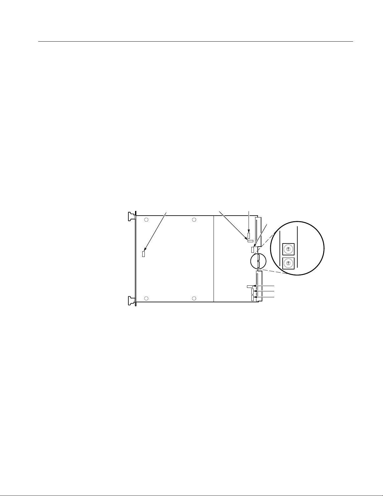
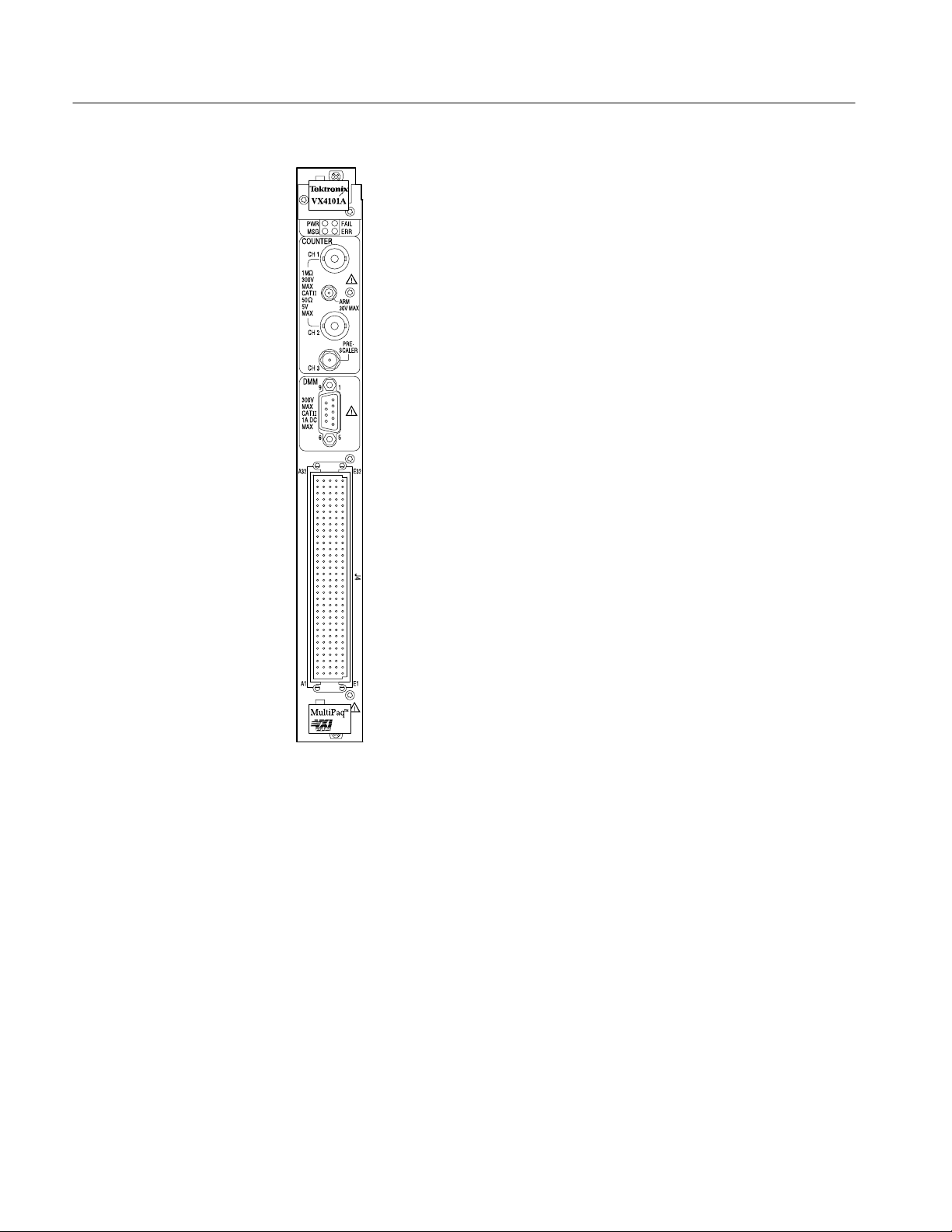
Figure 1–1 shows the VX4101A switches and fuses, and Figure 1–2 shows the
front panel.
Switches as viewed
F652 F651F01
from the rear of instrument
(labels are on the back shield)
F75
LOGICAL
ADDRS
HI
LO
F1351
F1352
F1451
Figure 1–1: VX4101A VXIbus Connectors, Fuses, and Switch Locations
VX4101A MultiPaq Instrument User Manual
1–7
Page 30
Product Description
Controls and Indicators
1–8
Figure 1–2: VX4101A Front Panel
The following logical address switches must be correctly set to ensure proper
operation. Refer to Figure 1–1 for their physical locations.
Logical Address Switches. The VX4101A supports VXI dynamic addressing. It is
shipped with the switches set to FF so that the Slot 0 will automatically assign
an address to the module.
Each functional module in a VXIbus System must be assigned a unique logical
address, from 1 to decimal 255 (hexadecimal FF).
VX4101A MultiPaq Instrument User Manual
Page 31

Product Description
NOTE. If you do not want to use dynamic addressing, align the desired switch
position with the arrow on the module shield.
The physical address of the instrument is on a 64 byte boundary. If the Logical
Address switch representing the most significant digit (LA-HI) of the logical
address is set to position X and the switch representing the least significant digit
(LA-LO) of the logical address is set to position Y, then the base physical
address of the module will be [(40
L.A. HI LO decimal hexadecimal
A
16
15
L.A. is the Logical Address
0
16
1
16
16
A
16
5
16
(64 * 10) + 49152 = 49792 (4016 * A16) + C00016 = C280
(64 * 21) + 49152 = 50496 (4016 * 1516) + C00016 = C540
× XY16) + C00016]. For example:
16
Base Physical Address
16
16
LEDs
Front Panel Connectors
The VX4101A has four LEDs visible on its front panel. These LEDs are labeled
as follows:
H Power LED – this LED is On if all six fuses for the six power buses are
intact. Any single fuse being blown results in the LED turning OFF
H Fail LED – this LED is normally OFF. During power-on or reset self-test,
the LED will be ON for the duration of the test. If the VX4101A detects a
failure during normal operation, the LED will come ON and the SYSFAIL
line on the backplane will be true
H Message LED – this LED flickers ON when the VX4101A is being
addressed on the VME backplane by its commander
H ERR LED – this LED is normally OFF. However, it may blink on and off to
indicate error conditions. The most common reason is a command syntax
error has been detected. Other error conditions that will cause the LED to
blink are discussed elsewhere in this manual. Sending the “SYSTem:ERRor?” query to the instrument will return the cause of the error. When all
errors in the queue have been retrieved, the error LED will return to the OFF
state
Refer to Appendix B:Input/Output Connections for more information.
VX4101A MultiPaq Instrument User Manual
1–9
Page 32

Product Description
Fuses
IEEE-488 Address
The VX4101A has 6 fuses that limit the amount of current that each module can
draw from the VXI backplane +5, -5.2, +24, -24, +12, and -12 V power pins.
These fuses protect the module in case of an accidental shorting of the power bus
or any other situation where excessive current might be drawn.
If any fuse opens, the module will assert SYSFAIL* on the VXIbus.
If the +5 V fuse opens, the VXIbus Resource Manager will be unable to assert
SYSFAIL INHIBIT to disable SYSFAIL*.
If any fuse opens, remove the fault before replacing the fuse. Replacement fuse
information is given in Appendix H: Replaceable Parts. Refer to the Separator
page, following page C-10, before performing any service to this product.
In order to use and program the VX4101A in an IEEE-488.2 environment, you
must know the IEEE-488 address of the module. Different manufacturers of
IEEE-488 interface devices have different algorithms for equating a logical
address with an IEEE-488 address. Consult the operating manual of the
IEEE-488 module being used.
Self-Test
VX4101A MultiPaqt
Instrument Self-Test
The VX4101A performs an interface self-test at power-on. This test ensures that
the VXIbus interface is fully functional and ready for communication with the
controller and that each instrument is initialized and ready for operation.
Built-In Test is provided by extensive self-tests which can be invoked via IEEE
488.2 and SCPI commands and queries.
The following are highlights of each test performed:
The self-test for the VX4101A MultiPaqtInstrument tests the following
components:
H CPU RAM
H CPU timers, including periodic trigger
H Internal CPU interrupts
H Software triggers
1–10
VX4101A MultiPaq Instrument User Manual
Page 33

Product Description
Counter Self-Test
Digital Input and Output
Self-Test
DMM Self-Test
The self-test for the Counter tests the following components:
H The two 4 Kb Counter measurement buffers.
H Logic registers
H The analog front end pre-amp offset, pre-amp inverter, and pre-amp gain
digital to analog converters (DACs).
H A 2.5 MHz signal is routed in through a test source and checked for
accuracy.
The self-test for the Digital Input and Digital Output includes a test of the Digital
Output hardware, as well as read/write/verify tests on shared memory and
read/write control registers.
The DMM self-test includes RAM testing, power supply and DMM reference
testing, amplifier and analog to digital converter testing, and control circuitry
testing. The self-test for the DMM tests the following components:
H The two 4 Kb DMM measurement buffers
H Logic registers
DAC Self-Test
Relay Drivers Self-Test
SurePatht Module
Self-Test
H Measurements of Ground are taken at the 30 mV DC range, 3 VDC range,
and 300 mV AC/DCV range
H The 2.75 V reference is tested in the 3 V range
The DAC performs the following self-test procedure:
H Read/write/verify test on shared memory
H Read/write/verify on all read/write control registers
There is no self-test for the Relay Drivers.
There is no automatic self-test for SurePath
query to test the control logic and data path for both the VX4101A and the
SurePathtcard in use. For more information on the TEST:ALL? query, see SCPI
Commands for the SurePath Modules in this manual
t modules. You use the TEST:ALL?
VX4101A MultiPaq Instrument User Manual
1–11
Page 34

Product Description
Accessories
T able 1–2: Standard Accessories
The following tables list the standard and optional accessories for the VX4101A:
Tektronix part
number
VX1784S 1 CONN HOODED; DE–9 FEMALE SOCKET TK2548
071–0049–XX 1 MANUAL,TECH:USERS,VX4101A TK2548 071–0049–XX
071–0051–XX 1 MANUAL,TECH:REFERENCE,VX4101A TK2548 071–0050–XX
063–2598–00 1 VXIplug&play 16-bit driver 063–2598–XX
063–2822–00 1 VXIplug&play 32-bit driver 063–2822–XX
Qty Name and description Mfr. Code
Mfr.
part number
T able 1–3: Optional Accessories
Tektronix part
number
VX1630 1 CABLE, ANALOG; 160 PIN CONN W/160 COND CBL
VX1630M 1 MOD KIT; VX4101 DMM MOD KIT FOR VX1630 CABLE, 3
VX1630S 1 160 PIN CON KIT; BAK SHL, PIN HOUSNG, 200 PINS
VX1729 1 CABLE,INTCON; COAX,VX1729;RFD,50 OHM,RG188,
VX1730 1 CABLE, ADAPTER; SMB SNAP ON PLUG TO PLUG
VX1760 1 SMA–BNC MALE; LE COAX CABLE, RFD50–OHM,
174–1428–00 1 CABLE ASSY:COAX,RFD,50 OHM,60.0L,SMA,STR,BOTH
012–0057–01 1 CA ASSY ,RF:COAXIAL,RFD,50 OHM,43 L,BNC,MALE 060D9 012–0057–01
003–1493–00 1 HAND TOOL:DISASSEMBLY TOOL FOR CRIMP & POKE
003–1494–00 1 HAND TOOL:HAND TOOL FOR LOOSE CRIMP & POKE
Qty Name and description Mfr. Code
TWISTED PAIRS, DE–9P MALE SUBMINIATURE, 24L
10 FT ,BNC,MALE X SMB,STR
1784S RG188, 10FT, BNC MALE–SMA, STR
060D9 174–1428–00
ENDS,MALE
6V439 471 555
CONT ACTS
6V439 014 374
CONT ACTS
Mfr. part number
1–12
VX4101A MultiPaq Instrument User Manual
Page 35

Performance Options
Product Description
You can purchase the following options to enhance performance of the
VX4101A:
T able 1–4: VX4101A Performance Options
Description Option Number
500 MHz Counter Channel One and
Channel Two
3 GHz Counter prescaler Channel
Three
Eight Channel DAC 1A
32 Bit Digital I/O with Eight Relay
Drivers
TCXO 1T
About the VXIplug&play Software
The VXIplug&play software included with the VX4101A consists of two
components:
H Device drivers
H Soft Front Panels (SFPs)
VXIplug&play device drivers enable you to operate the VX4101A under
program control.
The graphical user interfaces of the SFPs emulate the physical controls and
displays typically found on monolithic instruments. The instrument drivers call a
common set of I/O control functions that are independent of instrument types,
interface types, operating systems, programming languages, and networking
mechanisms.
1C
2C
1D
The installation program installs the VXIplug&play drivers for the framework
appropriate for your processing environment. The frameworks were developed as
established by the VXIplug&play Alliance. The possible frameworks are as
follows:
H WIN
H WINNT
H WIN95
VX4101A MultiPaq Instrument User Manual
1–13
Page 36

Product Description
Using the VXI plug&play
Software
Double clicking on the appropriate instrument icon launches the soft front panel
(SFP). The SFP displays a representation of the traditional controls and
indicators for an instrument. By selecting the appropriate controls on the SFP,
you can verify that the instrument has been correctly installed and is functional,
and perform almost all of the functions of the instrument. The SFP will:
H Control the instrument
H Display data
H Provide command line query and response (talk/listen)
H Provide error and event reporting
See Installation for instructions on installing and running the SFP and using the
C driver for program control. Detailed descriptions of the VXIplug&play drivers
are given in on-line Help and text files on the disk shipped with the instrument.
1–14
VX4101A MultiPaq Instrument User Manual
Page 37

Installation
This section contains the information you will need to install the VX4101A
MultiPaqtInstrument and its associated software, and to verify that the
instrument is functioning properly. This includes the following:
H Installing the VX4101A module in the mainframe
H Installing the VXIplug&play software
H Running a functional check
H Using the soft front panels (SFPs) included with the instrument
At the end of the section, you will find a checklist to summarize your installation
choices.
Installing the Module in the Mainframe
Installing the VX4101A in a Tektronix mainframe meets all instrument cooling
requirements.
Tools Required
Requirements and
Cautions
A slotted screwdriver set is required for proper installation.
The VX4101A is a C-size VXIbus instrument module and therefore can be
installed in any C- or D-size VXIbus mainframe slot other than Slot 0. To install
the module in a D-size mainframe, consult the operating manual for the
mainframe. Refer to Controls and Indicators for information on selecting and
setting the Logical Address switch of the module. This switch defines the
programming address of your module.
CAUTION. Note that there are two printed ejector handles on the card. To avoid
installing the card incorrectly, make sure the ejector marked “VX4101A” is at
the top. Installing it incorrectly may damage the DIN connectors on the module.
VX4101A MultiPaq Instrument User Manual
1–15
Page 38

Installation
NOTE. If the VX4101A is inserted in a slot with any empty slots to the left of the
module, the VME daisy-chain jumpers must be installed on the backplane in
order for the VXI Module to operate properly. Check the manual of the mainframe being used for instructions on jumper settings. If the jumpers are not
installed properly, there will be no interrupts and bus masters will not operate
properly. Jumpers are not necessary for auto-configuring backplane designs
such as those in Tektronix mainframes.
Module Installation
Procedure
Follow these steps to install the VX4101A:
CAUTION. The VX4101A Module is a piece of electronic equipment and therefore
has some susceptibility to electrostatic damage (ESD). ESD precautions must be
taken whenever the module is handled.
1. Record the revision levels, serial numbers (located on the label on the top
shield of the VX4101A), and switch settings on the Installation Checklist.
2. Verify that the switches are set to the correct values. Refer to Controls and
Indicators for more information on setting switches.
3. Make sure that the mainframe power is Off.
4. Insert the module into one of the instrument slots of the mainframe (see
Figure 1–3).
1–16
Figure 1–3: Module Installation
VX4101A MultiPaq Instrument User Manual
Page 39

CAUTION. Verify that the mainframe is able to provide adequate cooling and
power with this module installed. Refer to the mainframe Operating Manual for
instructions. If the mainframe cannot cool the unit adequately, the unit may not
operate properly and may be damaged.
Installing the VXIplug&play Software
Each VXIplug&play instrument includes either a 3 1/2 inch diskette or CD-
ROM storage media containing the SFPs and device drivers with which you can
control the instrument interactively. The SFPs are capable of controlling the
instrument immediately following a successful installation, without requiring a
specific application development environment. The soft front panels and the
supporting software were developed in conformance with the guidelines of the
VXIplug&play Systems Alliance.
All VXIplug&play products are classified within a particular framework, as
developed by the VXIplug&play Systems Alliance to categorize operating
systems, programming languages, and I/O software libraries. The framework
supported by the driver distributed with this VXI module is printed on the label
of the media.
Installation
About the Device Drivers
Installation Procedure
The source code as well as the dynamic link library (DLL) are distributed so that
you have the flexibility of using either of them in the end application.
The device driver distributed with the Tektronix VX4101A complies with all
current VXIplug&play requirements. The device driver uses VISA calls that are
portable across platforms and development environments. Tektronix uses only
the ANSI C implementation in instrument driver source code. No platform-specific libraries are included in the driver. The driver source code will compile
using MSVC, Borland, Symantec or Watcom compilers without having to use
foreign libraries, other than the VISA Dynamic Link Library (DLL). All driver
.DLL files are located in:
VXIPNP\<Framework>\BIN
Use the following procedure to install the VXIplug&play software:
1. Insert the media containing the driver files in the appropriate drive.
2. Locate the file Setup.exe, as follows:
H On a 3 1/2 inch floppy disk, the file is on disk 1
H On a CD-ROM, the file will be in the tkvx4101 directory
VX4101A MultiPaq Instrument User Manual
1–17
Page 40

Installation
3. Launch setup.exe as follows:
H In Windows or Windows NT/3.x, use the File menu and select Run.
Then, browse to find setup.exe or type the drive letter and program name
H In Windows 95 or or Windows NT/4.x, use Start and select Run. Browse
to locate setup.exe and click on OK
4. Follow the directions of the installation program.
Following installation, driver files (see list below) will be found in locations
defined by the VXIplug&play Alliance. Where required, modifications to your
autoexec.bat and system.ini files may be automatically completed.
Driver Files
The instrument driver for the VX4101A is distributed with a number of C source
code files, header files, dynamic link libraries and other supporting files. A
breakdown of the modules that the files control are as follows:
VX4101. This is the high level “controller” portion of the driver. This part of the
driver does the actual communication with the instrument. The tkvx4101.c or
tkvx4101.dll files have functions which perform VISA function calls. The other
modules, making up the total driver, call functions in the tkvx4101 to get system
configuration information and to communicate to each specific instrument.
Device-Specific Files. The files supporting the specific instruments are as follows:
T able 1–5: Instrument-Specific Files
Prefix Controls instrument
tkmpdmm DMM
tkmpctr Counter
tkmpscan SurePatht scanners
tkmpdac Digital to Analog Converter
tkmpdrv Relay Drivers
tkmpdigi Digital Input
tkmpdigo Digital Output
1–18
File Locations. For the VX4101A driver, the following files will be in the
VXIPNP\<Framework>\TKVX4101 directory:
tkvx4101.c
tkvx4101.fp
tkvx4101.mak
tkvx4101.def
VX4101A MultiPaq Instrument User Manual
Page 41

tkvx4101.hlp
tksf4101.exe
Supporting driver files will be located in the following directories:
VXIPNP\<Framework>\support\tkmpdmm:
tkmpdmm.c
tkmpdmm.fp
tkmpdmm.mak
tkmpdmm.def
tkmpdmm.hlp
VXIPNP\<Framework>\support\tkmpctr:
tkmpctr.c
tkmpctr.fp
tkmpctr.mak
tkmpctr.def
tkmpctr.hlp
Installation
VXIPNP\<Framework>\support\tkmpscan:
tkmpscan.c
tkmpscan.fp
tkmpscan.mak
tkmpscan.def
tkmpscan.hlp
VXIPNP\<Framework>\support\tkmpdac:
tkmpdac.c
tkmpsdac.fp
tkmpdac.mak
tkmpdac.def
tkmpdac.hlp
VXIPNP\<Framework>\support\tkmpdigo:
tkmpdigo.c
tkmpdigo.fp
tkmpdigo.mak
tkmpdigo.def
tkmpdigo.hlp
VXIPNP\<Framework>\support\tkmpdigi:
tkmpdigi.c
tkmpdigi.fp
tkmpdigi.mak
VX4101A MultiPaq Instrument User Manual
1–19
Page 42

Installation
tkmpdigi.def
tkmpdigi.hlp
VXIPNP\<Framework>\support\tkmprdrv:
tkmprdrv.c
tkmprdrv.fp
tkmprdrv.mak
tkmprdrv.def
tkmprdrv.hlp
VXIPNP\<Framework>\support\tkfdc:
tkfdc.c
tkfdc.fp
tkfdc.mak
tkfdc.def
tkfdc.hlp
The directories listed above contain several *.uir (User Interface Resource) files
that support the GUI executables (CVI files).
The following files are installed in the VXIPNP\<Framework>\INCLUDE
directory:
tkvx4101.h
tkmpdac.h
tkmpdigo.h
tkmpdigi.h
tkmprdrv.h
tkmpdmm.h
tkmpctr.h
tkmpscan.h
tkvx4101.bas
tkmpdac.bas
tkmpdigo.bas
tkmpdigi.bas
tkmprdrv.bas
tkmpdmm.bas
tkmpctr.bas
tkmpscan.bas
tkfdc.bas
The VXIPNP\<Framework>\BIN directory includes the following files:
tkvx4101.dll
tkmpdmm.dll
tkmpctr.dll
tkmpscan.dll
tkmpdac.dll
1–20
VX4101A MultiPaq Instrument User Manual
Page 43

Installation
tkmprdrv.dll
tkmpdigo.dll
tkmpdigi.dll
tkfdc.dll
The VXIPNP\KB directory includes the following files:
tkvx4101.kb
tkmpdmm.kb
tkmpctr.kb
tkmpscan.kb
tkmpdac.kb
tkmprdrv.kb
tkmpdigo.kb
tkmpdigi.kb
tkfdc.lib
The VXIPNP\<Framework>\LIB\MSC\ directory includes the following files:
tkvx4101.lib
tkmpdmm.lib
tkmpctr.lib
tkmpscan.lib
tkmpdac.lib
tkmprdrv.lib
tkmpdigo.lib
tkmpdigi.lib
tkfdc.lib
The .DLL files are tested in LabWindows/CVI, LabView, HPVEE, Visual Basic,
MSVC/C++ and Borland C/C++ before distribution. If you want to modify the
driver algorithms, all files are distributed to facilitate rebuilding the .DLL file
with the modifications.
NOTE. Tektronix recommends that you back up your original source files before
modifying the driver files
CAUTION. The Soft Front Panel (SFP) distributed with this driver is built using
the distributed .DLL files. Any modification to the .DLL files used by the SFP
could make it unusable. Re-installing the driver will write over any modified
files with the original files and restore SFP operation.
Installation parameters will vary depending on the mainframe being used. Be
sure to consult the mainframe operating manual before installing and operating
the module.
VX4101A MultiPaq Instrument User Manual
1–21
Page 44

Installation
Powering-On the VX4101A
The VX4101A instrument runs its interface test and is ready for communication
within five seconds. The VXIbus Resource Manager can add an additional delay.
The Power LED will be on. The Failed LED will be off. The default condition of
the module after power-on is listed in the *RST command description. For
information on the *RST command, see IEE488.2 commands.
The power-on sequence of the VX4101A meets the timing requirements of the
VXIbus specification and permits communications to begin even if the instrument has not completely initialized. At either power-on or a VXIbus reset, the
VX4101A initializes the VXIbus interface and all hardware and firmware
necessary to begin communication.
Preparing the Instrument
to Receive Commands
At this point, the VX4101A can receive the word serial Begin Normal Operations. A subset of instrument commands are available at this point to enable you
to query instrument status. For a full explanation of these commands, consult the
Syntax and Commands section. The available commands are as follows:
T able 1–6: Commands Available at Power-On
Command Syntax Command Type Description
*CLS IEEE 488.2 Clears all event status registers
and queues.
*ESE IEEE 488.2 Sets the contents of the IEEE
488.2 Standard Event Status
Enable Register.
*ESE? IEEE 488.2 Queries the contents of the IEEE
488.2 Standard Event Status
Enable Register.
*ESR IEEE 488.2 Sets the contents of the IEEE
488.2 Standard Event Status
Register.
*ESR? IEEE 488.2 Queries the contents of the IEEE
488.2 Standard Event Status
Register.
*RST IEEE 488.2 Resets VX4101A components to
their reset values.
1–22
NOTE: See the command summary for the *RST command in the section IEEE 488.2
Commands for the specific reset values.
*SRE IEEE 488.2 Sets the contents of the IEEE
488.2 Service Request Enable
Register.
VX4101A MultiPaq Instrument User Manual
Page 45

Installation
T able 1–6: Commands Available at Power-On (Cont.)
Command Syntax DescriptionCommand Type
*SRE? IEEE 488.2 Queries the contents of the IEEE
488.2 Service Request Enable
Register.
*STB? IEEE 488.2 Queries the contents of the IEEE
488.2 Status Byte Register.
ST ATus:OPERation:CONDition? Status and Events
Reporting System
ST ATus:OPERation:ENABle Status and Events
Reporting System
ST ATus:OPERation:ENABle? Status and Events
Reporting System
ST ATus:OPERation[:EVENt]? Status and Events
Reporting System
ST ATus:OPERation:NTRansition Status and Events
Reporting System
ST ATus:OPERation:NTRansition? Status and Events
Reporting System
ST ATus:OPERation:PTRansition Status and Events
Reporting System
ST ATus:OPERation:PTRansition? Status and Events
Reporting System
ST ATus:PRESet Status and Events
Reporting System
Returns the current operational
status of the VX4101A
Sets the Operational Enable
Register for the VX4101A
Queries the Operational Enable
Register for the VX4101A
Returns contents of Operational
Event Register for the VX4101A.
Sets the Operational Negative
Transition Filter for the VX4101A.
Queries the Operational Negative
Transition Filter for the VX4101A.
Sets the Operational Positive
Transition Filter for the VX4101A
Queries the Operational Positive
Transition Filter for the VX4101A
Clears the enable registers of all
Operational Status Registers, sets
all Positive Transition Filters, and
clears all Negative Transition
Filters
ST ATus:QUEue:ENABle Status and Events
ST ATus:QUEue[:NEXT]? Status and Events
ST ATus:QUEue:ENABle? Status and Event
ST ATus:QUEStionable[EVENt]? Status and Event
ST ATus:QUEStionable:CONDition?
ST ATus:QUEStionable:ENABle Status and Event
VX4101A MultiPaq Instrument User Manual
Reporting System
Reporting System
Reporting System
Reporting System
Status and Event
Reporting System
Reporting System
Allows you to specify which errors
and events, by error number,
should be placed in the error/
event queue
Returns next item from error/event
queue in FIFO order
Queries the Questionable Enable
Register for the VX4101A
Returns contents of Questionable
Event Register for the VX4101A
Returns contents of Questionable
Condition Register for the
VX4101A
Sets the Questionable Enable
Register for the VX4101A
1–23
Page 46

Installation
T able 1–6: Commands Available at Power-On (Cont.)
Command Syntax DescriptionCommand Type
ST ATus:QUEStionable:ENABle? Status and Event
Reporting System
Queries the Questionable Enable
Register for the VX4101A
ST ATus:QUEStionable:PTRansition
ST ATus:QUEStionable:PTRansition?
ST ATus:QUEStionable:NTRansition
ST ATus:QUEStionable:NTRansition?
SYSTem:ERRor? VX4101A MultiPaq
SYSTem:OPTions? VX4101A MultiPaq
SYSTem:READy? VX4101A MultiPaq
NOTE: Polling the instrument, i.e. querying it as fast as possible, might slow the completion of
the second initialization stage. You should have a delay of at least one second between
SYST em:READy? queries.
SYST em:SNUMber? VX4101A MultiPaq
SYSTem:VERSion? VX4101A MultiPaq
Status and Event
Reporting System
Status and Event
Reporting System
Status and Event
Reporting System
Status and Event
Reporting System
Instrument Commands
Instrument Commands
Instrument Commands
Instrument Commands
Instrument Commands
Sets the Questionable Positive
Transition Filter for the VX4101A
Queries the Questionable Positive
Transition Filter for the VX4101A
Sets the Questionable Negative
Transition Filter for the VX4101A
Queries the Questionable Negative Transition Filter for the
VX4101A
Returns in first-in first-out order
any error messages which have
been queued for any instruments
Returns the options for which the
VX4101A is currently configured
Queries for completion of the
power-on initialization sequence
for all instruments
This query returns the serial
number of the VX4101A
Returns the firmware version of
the VX4101A
1–24
NOTE. Until initialization is complete, the VX4101A will recognize only a limited
set of commands listed above. Attempting to enter any other command will
return a Command Not Found Error.
Querying the Instrument. If you are using SCPI commands to control the
instrument, use the following query to determine if the VX4101A has completed
its initialization sequence:
VX4101A MultiPaq Instrument User Manual
Page 47

Installation
The format and syntax for the command strings are described in the Command
Syntax section. A complete description if each command in alphabetical order is
in the Command Descriptions section.
Using VXIplug&play Device Drivers. If you are using instrument drivers to control
the VX4101A, instrument initialization occurs automatically. A SYStem:READy? query is sent upon execution of tkvx4101.init. For more information on
VXI plug&play instrument drivers, see the Installation section of this manual or
the online help accompanying the instrument.
LEDs at Power-On. At power-on following a successful interface test, the front
panel LEDs will be in the following states:
Power LED On
Fail Off
Message LED Off
ERR LED Off
SYSFAIL* Operation
Functional Check
SYSFAIL* will operate under the following circumstances:
If any fuse opens, the module will assert SYSFAIL* on the VXIbus.
If the +5 V fuse opens, the VXIbus Resource Manager will be unable to
assert SYSFAIL INHIBIT to disable SYSFAIL*.
NOTE. If a +5 V fuse opens, remove the fault before replacing the fuse.
Replacement fuse information is given in the Specifications section of the
manual.
A VXIbus hard reset occurs when another device, such as the VXIbus Resource
Manager, asserts the backplane SYSRESET* line. A VXIbus soft reset occurs
when another device, such as the Slot 0 Controller, sets the Reset Bit in the
VX4101A Control Register.
Self-Test
VX4101A MultiPaq Instrument User Manual
The VX4101A has a two level hierarchy of self-tests. At power-on or at a
VXIbus hard or soft reset, the instrument runs an extensive interface test. IEEE
1–25
Page 48

Installation
488.2 commands can be used to run more extensive self-tests of instrument
specific functions. During the interface test, or during a hard or soft reset, the
following actions take place:
1. The backplane SYSFAIL* line is asserted, indicating that the module is not
ready for communication.
2. A test of the VXIbus interface logic is performed.
3. Each instrument is configured to its *RST initial state.
4. On successful completion of the interface test, the backplane SYSFAIL* line
is negated and the VX4101A enters the VXIbus PASSED state (ready for
normal operation). If the interface test is not successful, the backplane
SYSFAIL* line remains asserted and the VX4101A enters the VXIbus
FAILED state.
Instrument Self-Tests. Instrument specific self-tests can be run at any time during
normal operations. To run self-test solely on the active instrument, send the
TEST:ALL? query. To test all instruments on the VX4101A, send the *TST?
query. See the instrument specific Syntax and Commands section for each
instrument for more detailed information on each self-test.
Operational Check
During a commanded self-test:
1. The backplane SYSFAIL* line is not asserted.
2. At the end of a successful instrument self-test, the instrument is placed in its
*RST (power-on) configuration.
3. At the end of a successful *TST?, the entire VX4101A will be placed in its
*RST (power-on) state.
This section tells you how to do an operational check of the VX4101A instruments using the soft front panel (SFP). Depending on the configuration you have
purchased, the operational check includes the following procedures:
H Standard configuration
H Option 1D configuration
H Option 1A configuration
1–26
VX4101A MultiPaq Instrument User Manual
Page 49

Installation
Operational Check for
Standard Configuration
To perform the operational check, do the following:
1. Double click on the TKVX4101A icon to start the SFP. The Tektronix
VX4101A MultiPaq SFP displays on the screen:
2. Launch the DMM by clicking on the DMM icon.
3. Click on Stopped and the DMM will take a DC Voltage measurement.
4. Close the DMM and launch the Counter by clicking on the icons.
5. Using the center pull-down ring control select DC Volts and click on the
Stopped button. The Counter will take a DC Voltage measurement.
6. Close the Counter and launch SurePath.
VX4101A MultiPaq Instrument User Manual
1–27
Page 50

Installation
7. Any SurePatht modules that are installed immediately to the right of the
VX4101A in the card cage will appear in the list box. Select the module
number that you want to use to close a relay.
NOTE. If there are no SurePatht modules in the system, the list box will be
empty and a Demo button will be available to the right of the list box. Use the
Demo button to show how the VX4101A works with SurePathtmodules.
Option 1D Operational
Check
8. Close SurePatht and do one of the following:
H Exit the Soft Front Panel
H Perform the operational check(s) for the options 1D or 1A
If you have purchased option 1D, your VX4101A includes the following
instruments:
H Digital Input
H Digital Output
H Relay Drivers
1. Perform the Option 1D operational check by launching the following
instruments:
a. Digital Input
1–28
VX4101A MultiPaq Instrument User Manual
Page 51

b. Digital Output:
c. Relay Driver:
Installation
Option 1A Operational
Check
2. Close the Digital Input, Digital Output, and Relay Driver and do one of the
following:
H Exit the Soft Front Panel
H Perform the operational check(s) for option 1A
If you purchased Option 1A, your VX4101A includes the Digital to Analog
Converter (DAC) . Perform the operational check as follows:
1. Launch the DAC:
2. Close the the DAC and exit the Soft Front Panel
VX4101A MultiPaq Instrument User Manual
1–29
Page 52

Installation
Installation Checklist
Revision Level: __________
Serial No.: __________
Mainframe Slot Number: __________
Switch Settings:__________
VXIbus Logical Address Switch: __________
Cable Installed (if any): __________
VXIplug&play software installed: __________
Notes
1–30
Performed by: _______________________ Date: _____________
VX4101A MultiPaq Instrument User Manual
Page 53

Operating Basics
Page 54

Page 55

About Global and Instrument Commands
The SCPI command set included with the VX4101A controls both overall
functions of the MultiPaqt instrument, and commands with unique behaviors
for each individual instrument associated with the
command set includes the following types of commands:
H Global commands
H Instrument commands
For detailed descriptions of global commands and specific commands for each
instrument module, see Syntax and Commands.
About Global Commands
Global commands and queries have the same behavior regardless of which
instrument you select. Examples of global commands include *RST, *IDN?, and
INSTrument:SELect.
MultiPaqtInstrument. The
About Instrument Commands
Instrument commands and queries have different behavior depending upon
which instrument you select. An example of an instrument class query is
MEASure:VOLT:DC?. This query is valid for both the DMM and the Counter,
but each instrument uses them differently.
The SCPI INSTrument:SELect command enables the VX4101A to differentiate
the same command, such as MEAS:VOLT:DC?, from its unique functionality
with each instrument. This command permits the MEASure command to be
directed to a specific instrument. An example of how each instrument uses the
associated INSTRument command is described in Syntax and Commands for
each each instrument.
NOTE. Only one instrument can be selected at a time. This is referred to as the
active instrument. The active instrument is the only device able to receive
commands. Other instruments can be executing previously entered commands or
queries, such as scan or measure commands, in parallel with the active
instrument.
VX4101A MultiPaq Instrument User Manual
2–1
Page 56

About Global and Instrument Commands
2–2
VX4101A MultiPaq Instrument User Manual
Page 57

VX4101A Operational Modes
The VX4101A MultiPaqtInstrument incorporates multiple instruments in a
single C-Size VXIbus slot. This maximizes functionality while minimizing cost
and space. The innovative design enables you to use each instrument of the
VX4101A as a conventional instrument compliant with IEEE 488.2 protocols.
You can also override IEEE 488.2 protocols and query multiple instruments
simultaneously. The two operational modes are as follows:
H Synchronous mode
H Asynchronous mode
For an example of how to use Asynchronous mode, see Using the VX4101A
MultiPaqtInstrument.
About Synchronous Mode
The Synchronous mode of the VX4101A is based on strict IEEE-488.2
compliance. In the 488.2 model, all instrument activity is sequential.
The IEEE 488.2 standard requires that a query be completed prior to the receipt
of any new commands or queries. A query is completed after the controller has
read the response. For more information on 488.2 compliance, see Chapter 6,
Message Exchange Control Protocol, of the IEEE 488.2 Standard.
Under 488.2 protocols, the other instruments are unavailable during a query. The
488.2 Message Exchange Protocol Enforcer (MEPE) restricts commands and
queries to another instrument module from being sent while a query is in
progress.
NOTE. The default settings for the VX4101A are fully IEEE-488.2 compliant.
About Asynchronous Mode
The multiple instrument architecture of the VX4101A enables you to send
commands to one instrument while receiving query responses from other
instruments. You receive the responses non-sequentially, which decreases test
times and lowers system costs. The instrument accomplishes this with an
alternate mode of operation, the Asynchronous Protocol.
VX4101A MultiPaq Instrument User Manual
2–3
Page 58

VX4101A Operational Modes
Asynchronous Protocol allows asynchronous query and command of instruments. When you enable the Asynchronous Mode, the VX4101A stores
responses in a queue. When you request data from this queue via a VXI read,
you receive responses in first-in, first-out (FIFO) order, regardless of which
instrument produced the response. Since these responses can be returned in a
different order than the queries, the VX4101A uses a different method of
associating a response with the associated query. This is described in a later
section entitled Response Formats.
The Asynchronous Protocol ensures that the response queue never blocks the
parser, as follows:
1. One entry in the queue is reserved for the overflow message.
2. If the queue becomes full, any subsequent writes to the queue will result in a
loss of the message.
If a message has been lost in this fashion, then the next VXIbus read will
result in transmission of the error message in the buffer overflow. Data
which is already in the response queue will remain there until it is read.
Asynchronous Mode
Commands
The 488.2 synchronization commands, *WAI, *OPC, and *OPC? are handled as
global synchronization devices by the Asynchronous Protocol. This allows you
to explicitly control the order of commands to multiple instruments on a single
device.
NOTE. Although it is possible to switch back and forth between strict 488.2
enforcement and the Asynchronous Protocol during instrument operation,
Tektronix recommends that you choose one mode or the other and leave the
instrument in that mode until it is reset. Switching back and forth during
operation could cause the instrument to enter an undesirable state under some
circumstances.
This section lists and describes the SCPI command set used in the Asynchronous
Protocol. The command structure is as follows:
This command allows you to choose between strict 488.2 protocol enforcement
and the Asynchronous Mode. The default state of this feature will be SYNChro-
nous, which implies strict 488.2 enforcement. An argument of ASYNchronous
enables the Asynchronous Mode. Both query and command are supported.
2–4
VX4101A MultiPaq Instrument User Manual
Page 59

VX4101A Operational Modes
If the currently selected language is SYNChronous, any attempt to use an
Asynchronous Mode command or query will generate the following error
message:
-210,“Settings conflict;Execute <:SYST:LANG ASYN> first”
SYSTem:RQUeue:SNUMber:STATe ON"|OFF"|1|0
This command turns the <sequence #> style of tags on or off. See the section
Response Formats for detailed information. Both query and command are
supported.
SYSTem:RQUeue:SNUMber[:SET] <seq #>
This command sets the next <sequence #> to be used. See the section Response
Formats for detailed information. Both query and command are supported.
SYSTem:RQUeue:QMODe [[ NEXT ] | ALL]
This command selects the instrument’s query mode while using the Asynchronous Protocol. Both command and query are supported.
Asynchronous Query
Responses
The default is the NEXT mode. In this mode, a VXIbus read is interpreted as
having been preceded by an implicit SYSTem:RQUeue[:NEXT]? query request-
ing the next entry from the queue. For every VXIbus read supplied, one response
will be returned from the response queue.
In the ALL mode, a VXIbus read is interpreted as having been preceded by an
implicit SYSTem:RQUeue:ALL? query requesting all entries currently residing in
the response queue. For every VXIbus read supplied, all entries in the response
queue will be returned in FIFO order, as one message separated by a semicolon.
The response queue is emptied as described under the SYSTem:RQUeue:ALL?
query.
When using Asynchronous Mode, query responses can be returned in a different
order than their associated queries. Each response must be tagged with a unique
identifier associating the response with the correct query. The general form of a
query response in the Asynchronous mode is as follows:
<tag>,<response>
The <tag> field can have two possible user-selectable formats:
H Sequence name
H Sequence number
VX4101A MultiPaq Instrument User Manual
2–5
Page 60

VX4101A Operational Modes
Sequence Name Format
This format shows each instrument name in ASCII format. In the default, the
<tag> field is defined as follows:
<instrument name>:<canonical query string>
The <instrument name> is the same name which would be used by the
command INSTrument:SELect <instrument name>. For global queries not
associated with a specific instrument, the <instrument name> used is VX4101A.
The <canonical query string> is based upon the original query which generated
this response. The canonical form is the query string expanded to include all
default nodes, with each node represented in its short form in upper case ASCII.
For example, if the MEAS:FREQ? query had been issued to the Counter, the
response from the queue using this format would be:
Counter:MEAS:FREQ?", 1.00000000000000E+07
When the VX4101A is using the Asynchronous Protocol and the response queue
is empty, a VXI word serial read will cause the VX4101A to return a default
message. This ensures that a query will not tie up the VXI backplane.
The <response> field is identical to the query response returned by the
instrument under strict IEEE 488.2 enforcement.
Sequence Number Format
NOTE. For queries taking a significant amount of time to return, it is possible to
use a software function, such as a service request generated by activity in the
SCPI Status registers, rather than polling for the response. This determines
when a response is available.
When there is no data in the response queue, the following response will be
generated in this mode:
VX4101A:RQU?,EMPTY
When there is an overflow in the response queue, the following response will be
generated in this mode:
VX4101A:RQU?,OVERFLOW
The second <tag> field format, which is selected with SYSTem:SNUMber:STATe
ON, is as follows:
<instrument number>:<sequence number>
The <instrument number> is the same number which would be used by the
command INSTrument:NSELect <instrument number>. For global queries not
associated with a specific instrument, the instrument number used is 0. The
sequence number is a one-up number assigned to a query as it is received by the
2–6
VX4101A MultiPaq Instrument User Manual
Page 61

VX4101A Operational Modes
card. As a query is received, it is assigned the current sequence number. The next
query received will have a sequence number one larger than the last.
NOTE. Note that sequence numbers are global to the card and have no direct
correlation with the instrument number.
The sequence number defaults to zero on power-on. To set the sequence number
to a desired value, use the following command:
SYSTem:RQUeue:SNUMber[SET]<sequence number>
After the instrument receives this command, the next received query will be
assigned the <sequence number> specified in the command. Each subsequent
sequence number will increment by 1 each time a query is received.
The query SYSTem:RQUeue:SNUMber[:SET]? can be used to determine what
the next sequence number will be. Since the response to this query will contain a
sequence number itself (assuming numerical tags are enabled), the response to
this query will be the sequence number which will be used by the next query
received.
For example, if the message is the sixth message in the queue and the Counter
identification number is 3, the response for the example above would be:
3:6,1.00000000000000E+07
The sequence number formats enable you to identify the instruments according
to your own unique requirements. Using the longer ASCII format allows you to
type commands into a talker/listener to get easily readable feedback about the
source of the current response. The more terse numerical format is easier to parse
in automated test software.
When there is no data in the response queue, the following response will be
generated in numeric mode:
0:Ć1,EMPTY
When the response queue has overflowed, the following response will be
generated in numeric mode:
0:Ć2,OVERFLOW
VX4101A MultiPaq Instrument User Manual
2–7
Page 62

VX4101A Operational Modes
2–8
VX4101A MultiPaq Instrument User Manual
Page 63

About Instrument Triggering
For digital multimeters, scanners, and sources such as the DAC and Digital I/O,
it is common to think of the devices as triggering to start an operation. For
counters, on the other hand, it is more common to think of the counter as arming
to take a measurement.
Triggering and arming the VX4101A and its associated instrument modules can
be considered to be the same operation. Any differences will be noted. For
example, in addition to the STARt arming source, the Counter implements a
STOP arming source. Counting is enabled when the start source is asserted and
disabled when the stop source is asserted.
Trigger Sources
For the SurePath master control, triggers are implemented in firmware, while
for the other instruments, the triggers are implemented in hardware. For this
reason, the SurePath timers have less resolution and accuracy than the other
instrument triggers. Since the SurePath trigger times are of the same order as
typical settling delays, impact to instrument performance is negligible.
T able 2–1: VX4101A Global Trigger Sources
Trigger Source
HOLD Instrument trigger source is disconnected from all trigger sources. If
you INITiate an instrument with a trigger source of HOLD, the
instrument will only enter the triggered state upon receipt of a
TRIGger:IMMediate command. This trigger is fixed.
IMMediate Device enter the triggered state immediately after receiving the INITiate
command. This trigger is fixed.
BUS Trigger source is either a word serial trigger command or the 488.2
common command *TRG. This trigger is delayable.
EXTernal This trigger source is derived from the front panel MultiPaq External
Trigger In, Pin24B signal. This input signal is common to all
instruments. This trigger is delayable.
TTL Trigger<0-7> One of the VXIbus TTL trigger lines. This trigger is delayable. TTLT
sources cannot be routed to other TTLT sources.
COMMand<0-4> One of five software command triggers. TRIG:FIR<N> is used to send
these triggers. This trigger is delayable.
TIMer Trigger source is the programmable periodic timer. This trigger is fixed.
SUREP ATH Trigger is generated whenever a scan line has switched and settled.
This trigger is delayable.
VX4101A MultiPaq Instrument User Manual
2–9
Page 64

About Instrument Triggering
T able 2–1: VX4101A Global Trigger Sources (Cont.)
Trigger Source
DMM Trigger is generated whenever the DMM has completed a measure-
ment. This trigger is delayable.
COUNTER Trigger is generated whenever the Counter has completed a
measurement. This trigger is delayable.
CTR_EXT ARM This trigger is the digital representation of the analog signal input into
the Counter front panel arm signal. This trigger is delayable.
DAC This trigger can have one of three modes, depending on how the DAC
is configured in trigger mode: it is generated either after each sample is
output, at the end of the current segment, or at the end of the
sequence.
This trigger is delayable.
DIGI This trigger is generated either after each sample is collected or when
the specified data has been collected. This trigger is delayable.
DIGO This trigger can have one of three modes, depending on how the
trigger mode is configured: it is generated after each sample is output,
at the end of a current segment, or at the end of the sequence. This
trigger is delayable.
T able 2–2: VX4101A Counter-Specific Trigger Sources
Trigger Source
CTR_CHAN2 The signal on channel two of the Counter can start a measurement on
channel one of the counter. This source is fixed and can only be used
as an ARM:STARt source on channel one of the Counter.
INTernal This fixed source is only valid as an ARM:STOP source and is used to
specify that other internal settings on the Counter (either the aperture
or delay-by-events counter) will be used to stop the Counter.
LEVel This fixed source is valid as an ARM:STOP source. It is used to specify
that the ARM:STARt source is level-sensitive instead of edge-sensitive.
The Counter will remain armed as long as the start source is asserted.
2–10
VX4101A MultiPaq Instrument User Manual
Page 65

About Instrument Triggering
Additional
Instrument-Specific
Trigger Sources
In addition to the above trigger sources, the Digital Multimeter (DMM), Digital
to Analog Converter (DAC), Digital Input, and Digital Output use the following
fixed source:
T able 2–3: VX4101A Fixed Trigger Sources for the DMM, DAC, Digital Input and
Digital Output
Trigger Source
HANDshake Derived from one of the front panel REQUEST signals. There is one
source for each instrument. When you select the handshake or trigger
source, the operation triggers on the leading edge of a programmable
polarity pulse of this signal. When the operation ends, the instrument
generates an acknowledge signal on the front panel ACKNOWLEDGE
STROBE signal associated with the generating instrument. Y ou can
also program the polarity of the ACKNOWLEDGE STROBE pulse.
For information on handshake pin assignments, see Appendix
B:Input/Output Connections. See Appendix A: Specifications for
additional information.
VX4101A Trigger Architecture
Figure 1 shows the trigger architecture of the VX4101A. Note that not all trigger
modes and sources are common to all instruments. Most trigger sources can be
routed to any of the VXIbus TTL trigger lines or to an external trigger output on
the front panel. The two types of trigger sources are as follows:
H Fixed trigger sources are always in pass-through mode
H Delayable trigger source supports three trigger modes: pass-through, delay
by time, and delay by trigger
VX4101A MultiPaq Instrument User Manual
2–11
Page 66

About Instrument Triggering
ARM:ST ARt Sources for Counter ARM:STOP Sources for Counter
BUS
EXTernal
TTLTrg<0-7>
COMMand<0-4>
SUREPATH
DMM
COUNTER
CTR_DIV_BY_N
CTR_EXTARM
DAC
DIGI
DIGO
HOLD
BUS
TIMer
EXT ernal
COMMand<0-4>
SUREPATH
DMM
COUNTER
CTR_DIV_BY_N
CTR_EXTARM
DAC
DIGI
DIGO
IMMediate
HOLD
TIMer
CHANnel2
Pass through
Delay-by-time
16-bit
1 MHz
Delay-by-triggers
(ECOunt)
16-bit
VXIbus TTL Trigger Sources
OUTP:TTLT<N>:SOUR
SurePath Trigger Sources
IMMediate
HOLD
COUNTER
ARM:STARt
IMMediate
HOLD
TIMer
BUS
TTLTrg<0-7>
COMMand<0-4>
SUREPATH
DMM
COUNTER
CTR_DIV_BY_N
CTR_EXTAR
DAC
DIGI
DIGO
Internal
Level
Pass through
Delay-by-time
16-bit
1 MHz
Delay-by-triggers
(ECOunt)
16-bit
COUNTER
ARM:ST op
VX4101A Trigger Output Sources
HOLD
BUS
TIMer
EXT ernal
TTLTrg<0-7>
COMMand<0-4>
SUREPATH
DMM
COUNTER
CTR_DIV_BY_N
CTR_EXTARM
DAC
DIGI
DIGO
OUTP:EXT :SOUR
DMM, DAC, Digital Input, and Digital Output Trigger Sources
Generated after
IMMediate
Operation is Complete
HANDshake
(strobe)
HANDSHAKE (request)
EXT ernal
TTLTrg<0-7>
COMMand<0-4>
SUREPATH
COUNTER
CTR_DIV_BY_N
CTR_EXTARM
2–12
BUS
DMM
DAC
DIGI
DIGO
TIMer
Pass through
Delay-by-time
16-bit
1 MHz
Delay-by-triggers
(ECOunt)
16-bit
SUREPATH
TRIG:STARt
BUS
EXT ernal
TTLTrg<0-7>
COMMand<0-4>
SUREPATH
DMM
COUNTER
CTR_DIV_BY_N
CTR_EXTARM
DAC
DIGI
DIGO
VX4101A MultiPaq Instrument User Manual
HOLD
TIMer
Pass through
Delay-by-time
16-bit
1 MHz
Delay-by-triggers
(ECOunt)
16-bit
DMM/DAC/
DIGI/DIGO
TRIG:STARt
Page 67

About Fast Data Channel (FDC) Operation
The following section tells you about using the Fast Data Channel (FDC), a
high-speed protocol for data transfer, with the VX4101A MultiPaqInstrument.
The VXIplug&play driver provided with the VX4101A implements FDC and
does not require full knowledge of the protocol. The description that follows is
only for users who choose not to use the driver.
NOTE. For more information on using VXIplug&play drivers to implement FDC,
see the online help files accompanying the driver software.
About FDC
Fast Data Channel (FDC) is a communications protocol for transferring data
between a VXIbus Commander device and its Servant device. The protocol is
standardized, approved by the VXIbus Consortium in a standard known as
VXI-10. It is supported by VXIbus instrument hardware and software vendors.
FDC was recognized as a supported protocol by the VXIplug&Play Alliance in
1996.
The FDC Process
FDC is a bi-directional, block oriented, data transfer mechanism that uses shared
memory and is well suited for transferring large buffers of data between a host
and a servant device. Bit flags in the FDC header word allow transfer of data
larger than the FDC buffer memory. Drivers supporting the protocol must exist
on each Host/Servant pair employing FDC.
The FDC protocol defines the establishing of FDC channels, setting up and
coordinating of the data transfers, channel termination, and error handling. In
order to use the FDC protocol for accessing instrumentation data, you must use
your application code to establish FDC channels, invoke FDC I/O drivers to
actuate the data transfer, close the the channels at termination, and handle any
errors that resulted from the data transfer. Vendor supplied I/O libraries are
generally required.
In a typical VXIbus instrumentation system, the Commander device is your host
computer, and the Servant device is the instrument. A typical user test application employing FDC would contain many of the following operations:
1. Establish a communication session with the instrument
VX4101A MultiPaq Instrument User Manual
2–13
Page 68

About Fast Data Channel (FDC) Operation
2. Configure and open the FDC channel
3. Transfer data via the FDC channel
4. Close the FDC channel
5. Terminate the instrument session
NOTE. The Commander/Servant hierarchical structure of the VXIbus architecture
requires the Commander device to initiate communication with the Servant
device.
Establish Communication Session
Open FDC Channels
Transfer Data Blocks
Close FDC Channels
Terminate Communication Session
Figure 2–1: Typical FDC Process
2–14
VX4101A MultiPaq Instrument User Manual
Page 69

About Fast Data Channel (FDC) Operation
Establishing a
Communications Session
Opening and Configuring
an FDC
Transferring Data Via the
FDC Channel
Before VXIbus instruments can communicate with each other, you must
establish an I/O linkage between the instruments. The complexity of this
communications session varies with the host environment, but typically involves
Operating System calls that return I/O driver reference handles. You must use
both Word Serial Protocol (WSP) as well as Fast Data Channel I/O drivers to set
up, configure, and terminate FDC channels. Only actual data buffer transfers use
the physical FDC channel.
After the WSP and FDC I/O drivers are established between the Commander and
Servant Device (typically a host computer and the instrument), an FDC channel
has to be configured and opened for operation. Configuring the channel defines
the transfer characteristics, such as access protocols, data width, and others.
Opening the channel identifies the particular FDC channel to be used, its
location in shared memory, and its maximum size.
NOTE. Multiple FDC channels may be established concurrently between a
Commander and Servant pair.
Data can be downloaded from the host to the instrument as well as extracted
from the instrument and transferred back to the host. Prior to the actual data
transfer, the host must define the direction of the data transfer. The transfer
operations work as follows:
Transferring Data from the Host to the Instrument. Source instruments are
candidates for FDC data transfers from the host to the instrument. In this
scenario, a buffer of data is transferred from the host application to the instrument for processing.
Data Transfers from the Instrument to the Host. Measurement instruments are
candidates for FDC data transfers from the instrument to the host. In this
scenario, a buffer of data is transferred from the instrument back to the host for
processing.
Bi-Directional Transfers. FDC channels can be bi-directional. For example, some
applications might require retrieval of blocks of data from a source instrument,
transmit blocks of data to a measurement instrument, or repeatedly transmit and
receive data between instruments.
VX4101A MultiPaq Instrument User Manual
2–15
Page 70

About Fast Data Channel (FDC) Operation
Closing the FDC Channel
Terminating the
Instrument Session
When your application program completes its FDC data transfer, you must close
the FDC channel to recover the system resources required to maintain the
channel, as well as to put the I/O connection in an appropriate state to re-establish a channel for the next FDC transfer.
This activity terminates the I/O session between the VXIbus instruments and
releases the I/O driver’s system resources.
FDC Operation with the DMM and DAC
The VX4101A MultiPaqInstrument uses FDC protocol only with the Digital
Multimeter (DMM) and the Digital to Analog Converter (DAC). The DMM is a
measurement device and generates data that is transferred back to the host. The
DAC is a source device and accepts data from the host. The DAC can also be
programmed to return data back to the host.
About Physical and
Logical Channels
The VX4101A FDC incorporates both physical and logical channels. The FDC
I/O drivers on the host and instrument device communicate with each other via
the physical FDC channel established between them.
Depending on the host application and the instrument configuration, you should
refer to the FDC channel in your application program with a logical channel
number. The logical channel number should always be the same for each
instrument that employs FDC.
FDC SCPI Commands
Each instrument’s logical FDC channel numbers range from 1 to the number of
FDC channels used by the instrument.
NOTE. Since the DMM and DAC each only support one FDC channel, their
logical FDC channel number is always 1.
To support the logical channel, however, your application software must retrieve
configuration information from the Servant device channel to supply to the
Host’s FDC drivers prior to using the FDC channel.
The VX4101A supports the FDC protocol with the VXI:FDC SCPI Subsystem.
The following commands comprise the FDC command set:
VXI[:SERVant]:FDC?
Returns comma separated list of physical FDC channel numbers assigned to
the VX4101A.
VXI[:SERVant]:FDC:SEL [<channel number>]
2–16
VX4101A MultiPaq Instrument User Manual
Page 71

About Fast Data Channel (FDC) Operation
Selects the FDC logical channel number.
VXI[:SERVant]:FDC:SEL?
Returns the FDC current logical FDC channel number.
VXI[:SERVant]:FDC:OPEN <mode> [,<channel number>]
Opens the selected FDC channel in the selected mode (Read Only, Write
Only or Read/Write).
VXI[:SERVant]:FDC:CLOSe [<channel number>]
Closes the selected FDC channel.
VXI[:SERVant]:FDC:CONFiguration?
Returns configuration data on FDC channel.
VXI[:SERVant]:FDC:BUFFer <buffer size>
Defines the size of data for a source instrument to return.
FDC Example
NOTE. See the Syntax and Commands section for the DMM or the DAC for a full
explanation of the VXI:FDC command subsystem.
The following scenario and example code demonstrates how you can use the
FDC data transfer capabilities of the VX4101A.
In this scenario, the Unit Under Test (UUT) is a device that processes a variety of
waveforms. You must write a production test that sequences through various
patterns to verify that the device processes the waveforms properly. The
VX4101A DAC instrument will be the source of the waveform pattern to the
UUT.
Because of the large amount of data to construct the waveforms, you will use
FDC to transmit the raw data from the host machine to the DAC. You will use a
VXIbus embedded computer as the host machine and will run the Commanderside FDC drivers supplied by the embedded computer’s VISA software.
NOTE. Please refer to the National Instrument’s NI-VISA Programmer’s
Reference Manual for a complete description of the command syntax used in
these examples.
VX4101A MultiPaq Instrument User Manual
2–17
Page 72

About Fast Data Channel (FDC) Operation
Establishing a
Communications Session
Configuring the FDC
Channel
You must establish the I/O linkage between the host and the VX4101A DAC.
You use both Word Serial Protocol (WSP) and FDC I/O drivers. Two communications sessions will be required: one for WSP and one for FDC.
Command Syntax. You use the following command syntax:
viOpen (session, resource name, access mode, timeout, vi);
Example Code. You can use the following code to open and close the FDC
session:
errs = viOpen (visaRM, VX4101Desc, VI_NULL,VI_NULL, &fdc);
errs = viOpen (visaRM, VX4101Desc, VI_NULL, VI_NULL , &wsp);
Successful execution of these commands returns the associated I/O driver
reference handle in the parameter pointed to by wsp or fdc.
In this section, you will prepare the FDC channel to transmit data.
Before Y ou Begin. Before the channel can be configured, the host needs to know
which physical FDC channels are supported by the instrument. You can retrieve
this information from the instrument by issuing the following query:
VXI:FDC?
This query returns a comma separated list of integers that represent the numeric
values of the physical FDC channels supported by the instrument.
Command Syntax. This is an ASCII command and is sent through the WSP
channel using the VISA functions, viRead and viWrite. Use the following the
syntax to program FDC to read and write data:
viRead (session, buff, max count, return count);
viWrite (session, buff, length(buff), return count);
Example Code for Configuring the FDC Channel. You can use the following code
to prepare the FDC channel to transmit data:
errs = viWrite (wsp, "VXI:FDC?", 8, &RetCnt);
errs = viRead (wsp, buff, sizeof(buff), &RetCnt);
fdc_physical_channel = atoi(buff);
2–18
VX4101A MultiPaq Instrument User Manual
Page 73

About Fast Data Channel (FDC) Operation
Since the DMM and DAC only have 1 FDC channel, the list returned by either
device contains a single channel value. This physical FDC channel number is
passed to the host FDC drivers through the Host session with a viSetAttribute
command. Use the following command syntax:
viSetAttribute (vi, attribute, attribute state);
Example Code for Passing Values to the Drivers. You can use the following
sample code to pass the channel values to the FDC drivers:
errs = viSetAttribute (fdc, VI_ATTR_FDC_CHNL,
fdc_physical_channel);
The Commander and Servant FDC drivers are now assigned to the same physical
channel.
Other Attributes
Opening the FDC Channel
Other FDC attributes may also be specified. The host computer vendor’s FDC
support documentation will detail all the configuration parameters required for
your FDC driver implementation.
After the FDC drivers are configured, you must command the servant device to
open the logical FDC channel associated with its physical channel. The
FDC:SEL? query returns the currently selected logical fdc channel:
errs = viWrite (wsp, "VXI:FDC:SEL?", 12, &RetCnt);
errs = viRead (wsp, buff, sizeof(buff), &RetCnt);
fdc_logical_channel = atoi(buff);
NOTE. For the VX4101A DAC and DMM, the above query always returns a 1.
You do not need to use this query.
The Open command opens the selected FDC channel in the selected mode, in
this case, Read/Write.
Example Code for Opening the Channel.
sprintf(buff,"VXI:FDC:OPEN RW %u",fdc_logical_channel);
errs = viWrite (wsp, buff, strlen(buff), &RetCnt);
The VX4101A is comprised of a number of independently operating instruments.
The previous OPEN command requires the servant device to set up and initialize
some of the instrument’s internal resources. The time it takes to complete this
VX4101A MultiPaq Instrument User Manual
2–19
Page 74

About Fast Data Channel (FDC) Operation
process varies with the VX4101A configuration and behavior at the time the
OPEN command is issued. To ensure that an opened FDC channel is not used to
transfer data until it is ready to do so, you should poll the FDC channel to
determine if it is ready for data transfers.
The configure query returns the state of the currently selected FDC channel. In
this case, the channel state must be READ_WRITE before data transfer can
reliably commence.
Example Code for Querying the Channel.
while(strncmp(buff,”READ_WRITE”,10))
{
errs = viWrite (wsp, "VXI:FDC:CONF?", 13, &RetCnt);
errs = viRead (wsp, buff, sizeof(buff), &RetCnt);
buff[RetCnt] = 0;
Transferring Data
}
After configuring and opening the FDC channel, data transfers can begin. You
can use FDC to quickly and efficiently program an output waveform.
Using ASCII Values. The VX4101A DAC can also be programmed for an output
waveform with easy to use, but slow, ASCII values. When programmed in
ASCII, the DAC converts the ASCII voltage values to binary data prior to
driving its output hardware. When programmed with FDC, the data transferred to
the DAC must already be in a binary format suitable for driving the hardware.
In a typical application, you develop waveform patterns with ASCII data. Then,
using FDC, the instrument reads back the binary representations of the waveform
patterns. During the execution of the production test, the binary representations
of the waveforms can be downloaded to the DAC with FDC. This provides a
mechanism to rapidly and efficiently transmit a variety of different waveforms
from the DAC to the Unit Under Test.
The DAC is specialized for outputting waveforms in real time. In order to read
back its output buffers, you must define the amount of data to return. Reception
of the return count command signals the DAC to present its output data to the
FDC drivers. In the following example code, assume the DAC has already been
programmed with ASCII voltage values. The BUFF command defines the return
count of the data that was read back and the viRead command invokes the host
FDC driver’s read function to retrieve the data via FDC.
2–20
VX4101A MultiPaq Instrument User Manual
Page 75

About Fast Data Channel (FDC) Operation
Example Code for Retrieving Data. Use the following example code to retrieve the
data:
errs = viWrite (wsp, "VXI:FDC:BUFF 1024", 17, &RetCnt);
errs = viRead(fdc, buff, sizeof(buff), &RetCount);
Once the waveform has been returned to the host in binary format, the data can
be re-sent to the VX4101A DAC with the host FDC driver’s write function.
Example Code for Re-Sending Data.
errs = viWrite (fdc, buff, strlen(buff), &RetCnt);
Closing the FDC Channels
Terminating the
Communication Session
Reading and writing the FDC channel can be repeated until you have completed
testing the unit. At that point the program could close down the FDC channels in
preparation for connecting and testing another device.
Example Code for Closing the FDC Channels. You can use the following code to
close the FDC channels:
errs = viWrite (wsp, "VXI:FDC:CLOSE",13, &RetCnt);
When all testing is complete, you can terminate the I/O sessions and shut down
the test equipment. Use the following command syntax:
viClose(vi);
Example Code for Terminating the Communication Session. You can use the
following code to terminate the session:
errs = viClose (fdc);
errs = viClose (wsp);
VX4101A MultiPaq Instrument User Manual
2–21
Page 76

About Fast Data Channel (FDC) Operation
2–22
VX4101A MultiPaq Instrument User Manual
Page 77

Using the VX4101A MultiPaqt Instrument
This section includes guidelines and procedures for the following operations of
the VX4101A MultiPaqtInstrument:
H Using Asynchronous Mode
Using Asynchronous Mode
Using Asynchronous Mode, the VX4101A can return responses in a different
chronological order than their associated queries. To keep track of the actual
order in which the responses are returned, the VX4101A MultiPaqtInstrument
assigns a unique tag to each response. You can define two different formats in
which to receive tags:
H ASCII format, which provides feedback in a more easily readable format
H Numeric format, which is more terse, but is easier to parse in automated test
software
For more information on VX4101A query formats, see VX4101A Operations.
Starting Sequence
Number
In the following example the instrument is set up to return queries using ASCII
tags.
This example shows how you can use the Asynchronous Protocol to send
multiple queries without intervening VXIbus reads and still associate queries and
responses, regardless of the order in which they are sent and received.
NOTE. This example assumes that a 1 MHz signal is connected to channel 1 of
the counter and a 0.1 Volt DC signal is connected to the DMM.
Prerequisites In order to get the responses shown in the following procedures,
the instrument must have previously performed a word serial read.
NOTE. In the strict 488.2 example, sending the word serial read prematurely
could cause a bus timeout. In the Asynchronous Protocol examples, performing a
word serial read would simply cause the default empty message to be returned.
1. Enter the following command to select Asynchronous Mode:
VX4101A MultiPaq Instrument User Manual
2–23
Page 78

Using the VX4101A Multipaq Instrument
2. Enter the following query for error conditions:
SYST:ERR?
After a VXIbus read, the instrument returns the following response (note the
<tag> field preceding the response):
"VX4101A:SYST:ERR?",0,"No error"
3. Send the following two queries without performing an intervening VXIbus
read:
*IDN?
INST:CAT?
Two VXIbus reads in succession will return the following responses:
"VX4101A:*IDN?",Tektronix, VX4101A, B010101, Firmware
v.2.0.0/SCPI:95.0
"VX4101A:INST:CAT?",VX4101A,SurePath,DMM,Counter,DAC,DIGI,
DIGO,RDriv
4. Enter the following command to select the DMM:
INST:SEL DMM
5. Send the following query to set up and acquire a 10V DC measurement:
MEAS:ARR:VOLT:DC? 10,MIN,MAX
NOTE. This measurement takes approximately 35 seconds to complete.
6. Without attempting to read the response to the DMM query, immediately
select the Counter with the following command:
INST:SEL Counter
7. Send the following query to measure the frequency of the signal on channel
one of the Counter:
MEAS:FREQ?
8. A VXIbus read will return the result of the counter measurement:
2–24
"Counter:MEAS:SCAL:FREQ?",1.00000000000000E+06
9. Another VXIbus read returns a message indicating that the message queue is
empty:
"VX4101A:RQU?","EMPTY
VX4101A MultiPaq Instrument User Manual
Page 79

Using the VX4101A Multipaq Instrument
10. Approximately 30 seconds after the DMM measurement was initiated, the
results will be ready. At this point a VXIbus read will return these results:
"DMM:MEAS:ARR:VOLT:DC?",#3130+1.00000E-01,+1.00000E-01,+1.000
00E-01,+1.00000E-01,+1.00000E-01,+1.00000E-01,+1.00000E-01,+1
.00000E-01,+1.00000E-01,+1.00000E-01
11. Another VXIbus read returns a message indicating that the message queue is
once again empty:
"VX4101A:RQU?","EMPTY
VX4101A MultiPaq Instrument User Manual
2–25
Page 80

Using the VX4101A Multipaq Instrument
2–26
VX4101A MultiPaq Instrument User Manual
Page 81

Using the Counter
This chapter contains procedures and hardware tips for using the Counter for the
following measurements:
H Measuring frequency
H Measuring time interval
H Measuring rise time
What You Should Know About
See the Appendix Counter Architecture for a block diagram of how the Counter
front end is constructed.
Measuring Frequency
In this procedure, you will make a frequency measurement using a 10 nS
aperture.
1. Select the Counter:
INST:SEL COUNTER
2. Set the input 1 coupling to DC:
INPut:COUPling DC
3. Set input 1 impedance to 50 W:
INPut:IMPedance 50
4. Set the aperture to 10 nanoseconds:
SENSe:FREQ:APER 1e-8
5. Configure the Counter to read frequency:
SENSe:FUNCtion "FREQuency"
6. Initiate the configuration and take the measurement:
INIT
7. Retrieve the measured data:
FETCh?
VX4101A MultiPaq Instrument User Manual
2–27
Page 82

Using the Counter
Measuring Time Interval
In this procedure, you will make a time interval measurement using external
gating.
1. Select the Counter:
INST:SEL COUNTER
2. Set the input 1 coupling to DC:
INPut:COUPling DC
3. Set input 1 impedance to 50 W:
INPut:IMPedance 50
4. Set the input 1 signal lowpass filter state On:
INPut:FILT ON
5. Select the start arming source to be used after the Counter is initiated:
ARM:SOURce CTR_EXTARM
6. Select the start arming source to be used when the Counter is initiated:
ARM:STOP:SOURce COUNTER
7. Select the Time Interval function without changing most of the Counter
setup:
SENSe:FUNCtion "TINTerval"
NOTE. Input coupling and impedance are not changed.
8. Set the aperture to minimum:
SENS:APER MIN
9. Initiate the configured measurement:
INIT
NOTE. Need application specific delay to allow time for triggers to occur.
2–28
10. Retrieve the measured data:
FETC?
VX4101A MultiPaq Instrument User Manual
Page 83

Measuring Rise Time
Using the Counter
In this procedure, you will make a rise time measurement using a 10 ns aperture
time.
Programming Example
1. Select the Counter:
INST:SEL COUNTER
2. Set input 1 coupling to DC:
INPut:COUPling DC
3. Set input 1 impedance to 50 W:
INPut:IMPedance 50
4. Sets the aperture to 10 nanoseconds:
SENSe:RTIMe:APER 1e-8
or
SENSe:RISE:TIME:APER 1e-8
5. Configure the Counter to read signal Rise Time:
SENSe:FUNCtion "RTIMe"
or
SENSe:FUNCtion "RISE:TIME"
6. Initiate the configuration and take the measurement:
INIT
7. Retrieve the measured data:
FETCh?
VX4101A MultiPaq Instrument User Manual
2–29
Page 84

Using the Counter
Measuring Time Interval with Delay
Programming Example
1. Select the Counter:
INST:SEL COUNTER
2. Set input 1 coupling to DC:
INPut:COUPling DC
3. Set input 1 impedance to 50 W:
INPut:IMPedance 50
4. Set the input 1 signal lowpass filter state to On:
INPut:FILT ON
5. Set the input 1 to an expected peak-to-peak input voltage and an expected
input offset voltage:
INPut1:SETup 2,1
6. Set input 2 coupling to DC:
INPut2:COUPling DC
7. Set input 2 impedance to 50 W:
INPut2:IMPedance 50
8. Set the input 2 signal lowpass filter state to On:
INPut2:FILT ON
9. Set the Input 2 to an expected peak to peak input voltage and an expected
input offset voltage:
INPut2:SETup 2,1
10. Select the Time Interval with delay by time function:
SENSe[1,2]:FUNCtion "TINT:DEL:TIME"
NOTE. This command will not change most of the setup for the Counter. Input
coupling and impedance are not changed
11. Set the delay to 1 msec:
SENS:TINT:DELay: 1e-3
2–30
VX4101A MultiPaq Instrument User Manual
Page 85

Using the Counter
This will return the time interval from the first edge on channel one to the
first edge on channel two that is at least 1 msec later.
12. Set the aperture to minimum:
SENS:APER MIN
13. Initiate the configured measurement:
INIT
14. Place the result of the measurement in the output buffer so you can read it:
FETch?
15. Set the time interval with delay by events:
SENSe12:FUNCtion "TINT:DEL:EVEN"
16. Set the number of events to 10:
SENSe:TINTerval:DELay:EVENTS 10
This will return the time interval from the first edge of channel one to the
tenth edge on channel two.
17. Initiate the configured measurement:
INIT
18. Place the results of the measurement in the output buffer so you can read
them:
FETC?
VX4101A MultiPaq Instrument User Manual
2–31
Page 86

Using the Counter
2–32
VX4101A MultiPaq Instrument User Manual
Page 87

Using the Digital Input
This section includes guidelines and procedures for the following operations of
the Digital Input:
H Program the Digital Input
H Read the current input
H Read points using external handshake
What You Should Know About
Start-Up
Shared Pin Assignments
with Digital Output
Digital Output Source
Upon start-up, all Digital Input pins are active.
Since both the Digital Input and Output share the same pins, the Digital Input
detects any voltage applied to the Digital Output. The 32 pins of the Digital
Input physically share the same pins with the Digital Output. If you are using
both the Digital Input and Digital Output, each common pin will be set to low if
either the Digital Output or your connection to the Digital Input drives it low.
If the Digital Output source is external and no external voltage is applied, the
Digital Input level of unconnected Digital inputs will be affected by other
connected Digital Inputs.
Pin Usage for Only the Digital Input. If you are not using the Digital Output, then
you should select one of the following internal excitation values:
H 5 VDC
H 12 VDC
H 24 VDC
Select the level based on whether the measured inputs are nominal 5 VDC or
less, 12 VDC or less, or higher than 12 VDC.
About Triggering
VX4101A MultiPaq Instrument User Manual
You can program the Digital Input to trigger as follows:
H Normal triggers
H On a pattern
2–33
Page 88

Using the Digital Input
Programming the Digital Input
This section describes how to program the Digital Input using the described
command set.
1. Select the Digital Input as the active instrument:
INST:SEL DIGI
2. Set the return format to hexadecimal:
FORMAT HEX
3. Enable all bits as input:
SENSE:PSELECT:DIGLOBAL ENAB
4. Set up the Digital Input to take 1000 postmatch measurements:
sens:arr 1000
5. Set up the threshold value to 2.8 V:
sense:threshold 2.8
6. Set the match pattern:
trig:matc #h00007e38
7. Set the mask for the match pattern:
trigger:mask #h0000FFFF
8. Start the measurements:
initiate
NOTE. Until the match occurs, the instrument will not take the 1000 post-match
measurements. You must manually enter the match pattern in order to use this
example.
9. Query the amount of prematch data
FETch:COUNt?
10. Retrieve all postmatch data:
FETch?
2–34
VX4101A MultiPaq Instrument User Manual
Page 89

Reading Current Input
Using the Digital Input
This procedure will show you how to read current input to the Digital Input.
1. Select the Digital Input as the active instrument:
INST:SEL DIGI
2. Set the data format to hexadecimal:
FORMat HEX
3. Enable all input bits:
INPut:PSelect:DIGLobal ENAB
4. Set up the read operation:
CONF:DIGL 2.5
5. Initiate measurement:
INIT
6. Retrieve the most recent values:
FETch?
Reading Points Using the External Handshake Feature
This procedure will show you how to read input points using handshake signals.
1. Select the Digital Input as the active instrument:
INST:SEL DIGI
2. Set the data format to hexadecimal:
FORMat HEX
3. Set up the read:
CONF:DIGL 2.5
4. Set up the instrument to make 20 measurements:
sense:arr 20
5. Program the instrument for one trigger and handshake:
trig:mode once
VX4101A MultiPaq Instrument User Manual
2–35
Page 90

Using the Digital Input
6. Program the instrument for the external handshake:
trig:source handshake
7. Manually send 20 external input strobes
8. Retrieve the number of measurements taken:
fetch:count?
9. Retrieve the data taken by the measurements:
Fetch?
2–36
VX4101A MultiPaq Instrument User Manual
Page 91

Using the Digital Output
This section includes guidelines and procedures for the following operations of
the Digital Output:
H Outputing one 32-bit word
H Outputing a sequence
What You Should Know About
About Segments and
Sequences
Shared Pins With the
Digital Input
You should understand the following definitions:
Segments: a programmable number of points
Sequence: a programmable number of segments
The Digital Output is connected to the Digital Input. The 32 pins of the Digital
Input physically share the same pins with the Digital Output.
Pin Usage With Digital Input and Output T ogether. Common pins used by both the
Digital Input and Digital Output will be driven low if either instrument drives it
low.
NOTE. If you are using the Digital Input and want to use a pin only as an input,
you must reset the Digital Output for pin to the default state of High.
VX4101A MultiPaq Instrument User Manual
2–37
Page 92

Using the Digital Output
Outputing One 32-Bit Word
This procedure will show you how to continuously output a 32-bit word at a
specified frequency with the Digital Output.
1. Select the Digital Output:
2. Load the first memory location:
3. Load the sample rate at the specified frequency:
4. Set the trace length:
5. Specify continuous output:
INST:SEL DIGO
TRACe 1,<data>
TRACe:SRATe <sample output frequency>
TRACe:Points 1
INIT:CONTinuous ON
6. Begin the sampling operation:
TRIGger:IMMEDiate
2–38
VX4101A MultiPaq Instrument User Manual
Page 93

Outputing a Sequence
Using the Digital Output
This procedure will show you how to output a sequence of x segments of y
points with the Digital Output. The internal clock is set to 1 kHz.
1. Select the Digital Output:
INST:SEL DIGO
2. Define the number of data points:
TRACe (1:Y),<data 1,...,data Y>
3. Set the output sample frequency to 1 kHz:
TRACe:SRATe 1000
4. Set the segment length to the number of data points Y:
TRACe:Points Y
5. Set the sequence number:
TRIG:MODE SEQuence, <number of segments>
6. Initiate the configuration:
INIT:IMM
VX4101A MultiPaq Instrument User Manual
2–39
Page 94

Using the Digital Output
2–40
VX4101A MultiPaq Instrument User Manual
Page 95

Using the Digital Multimeter
This section shows you how to make the following types of measurements with
the Digital Multimeter (DMM):
H DC Voltage
H AC Voltage
H Resistance
H Current
What You Should Know About
MEASure and CONFigure
Commands
The following command subsystems enable you to take measurements:
H MEASure
H CONFigure
The MEASure subsystem requires less specific knowledge of the DMM. The
MEASure commands configure the instrument for the measurement, initiates the
measurement, and returns the data.
The CONFigure command configures the instrument for a specific measurement
and allows more specific instrument parameters to be set before a measurement
is made. For example, you can control aperture settings and initialization. You
use CONFigure along with two other command subsystems:
H INIT
H FETCh?
The INIT command initiates the measurement. The FETCh? commands return
the measured data. MEASure can be used in place of the CONF, INIT, and
FETCh? commands in the measurement procedures below.
The READ? query initiates a measurement and returns the measured data in one
step. READ? can be used in place of INIT and FETCh? in the procedures below.
Selecting the Input
Impedance
VX4101A MultiPaq Instrument User Manual
The VX4101A has a default 10 MW input impedance (± 5%) following power up
for all voltage ranges. This input impedance is the result of the 10 MW resistance
ladder in the VX4101A provided for attenuation of voltages greater than 3 VDC.
This is usually not an issue for most measurements. However, if the signal you
are measuring has a source or output impedance of greater than 100 W, you
2–41
Page 96

Using the Digital Multimeter
might receive errors resulting from this impedance. A voltage divider circuit is
created by the measurement source impedance and the VX4101A input
impedance. For example, a 1000 W source impedance loaded by the VX4101A
10 MW input impedance will result in a .01% error.
For voltage measurements less than 3 VDC, this error may be essentially
eliminated by sending the command INPut:IMPedance 10e9. Since an attenuator
is not required for the lower voltage ranges, this command is provided to switch
out that attenuator, if desired.
About Low Level DC
Measurements
The VX4101A in the 30 mV DC measurement range has a resolution of 100 nV.
The accuracy at 0 VDC is between 8 mV and 15 mV depending on aperture
selection. At this low level of operation, the primary contributions to the error in
ambient temperature applications are the DC low range input amplifier voltage
and current noise and drift with time and temperature, and thermal EMF drops in
the range changing relays. These errors are minimized with the use of low drift
amplifiers and low thermal EMF relays in the VX4101A.
Cabling and aperture selection are vital in order to attain these measurement
accuracies. The primary source of additional error when you make an actual
measurement is normal mode power line noise. Normal mode power line noise is
differential noise between the high and low input that can easily be coupled into
your cabling. Since it is differential noise between the high and low input it
looks to the DMM like an actual input voltage.
To minimize these errors at low-level measurements, you should use shielded
twisted pair cabling to connect to the DMM. Since the VX4101A has a floating
front end, the low input of the VX4101A is not grounded. If your measurement
is referenced to ground, the best place to provide the ground reference is at your
equipment. If the measurement is referenced to ground, it is probably already
grounded within your unit somewhere. The DMM low side should not be
grounded. This will only create a ground loop adding potential error. Finally,
using an aperture that is a power line period multiple will provide significant
power line rejection as discussed in About Power Line Noise, below.
2–42
Low level errors are also minimized by using the autozero capability of the
VX4101A. Autozero minimizes long term drift errors in the input amplifier by
comparing a null reading taken during autozero with a reference null reading
taken when the VX4101A was last calibrated and compensating for any
difference. The autozero function also eliminates a portion of temperature drift
errors in applications where the temperature drifts slowly.
VX4101A MultiPaq Instrument User Manual
Page 97

Using the Digital Multimeter
About Power Line Noise
and Common Mode
Rejection
Three sets of common mode specifications are provided for the VX4101A:
H DC Common Mode Rejection
H AC Common Mode Rejection
H AC Effective Common Mode Rejection
Power line noise is generally at a frequency of 60 Hz or 50 Hz depending on the
power system prevalent in the area of the world where you are located. 400 Hz is
often prevalent in avionics applications. The VX4101A minimizes errors due to
power line noise at these frequencies. This rejection is provided by a combination of the VX4101A floating front end and the resulting common mode
rejection, and by the aperture programming provided.
Power line errors (typically injected into the measurement cabling) are of two
types, differential mode errors and common mode errors. Differential mode
errors, as described above, may be reduced by proper cabling and by selection of
aperture. Common mode errors are those equally injected onto both lines of the
measurement cabling. They are reduced by proper cabling, by selection of
aperture, and by the VX4101A AC common mode rejection.
Proper aperture selection for power line noisy environments may be easily
selected by using the SENS:NPLC command. This permits selection of apertures
that are an integer number of power line cycles. The VX4101A is initially
shipped assuming operation in a 60 Hz environment. For 50 Hz and 400 Hz (a
multiple of 50 Hz), the CALibrate:LFRequency command is provided to select
multiples of 50 Hz periods when the SENS:NPLC command is used. The
CAL:LFR command is included in the CALibrate command subsystem so the
latest selection may be stored in non-volatile memory on the VX4101A. As
such, you need only send the command once on receipt of your equipment,
although you may find it easier just to include it in the initialization sequence of
your test program.
Normal mode rejection specifications are specified at the particular frequency of
interest within some tolerance. You can reject frequencies outside that tolerance,
if they are high enough, by choosing an aperture that is a multiple of that
frequency, or for broadband noise by choosing as large an aperture as is
consistent with test time requirements. The amount of rejection for any
frequency and aperture may be determined by integrating the noise signal over
the aperture time and determining the resulting DC error.
VX4101A MultiPaq Instrument User Manual
2–43
Page 98

Using the Digital Multimeter
Making a DC Volt Measurement
This procedure will show you how to make a DC measurement with the DMM.
Hardware Tips
Programming Example
DC voltage measurements are made by connecting to pins 6 V+ and 1 V– of the
D-sub connector.
Do the following to perform a DC voltage measurement on the DMM:
1. Select the DMM:
INST:SEL DMM
2. Configure the DMM to take a DC measurement in the 30 V range with
minimum resolution:
CONF:VOLT:DC 30, MIN
3. Initiate the measurement:
INIT
4. Retrieve the measurement results:
FETCh?
Making AC Volt Measurements
Hardware Tips
Programming Example
2–44
AC voltage measurements are made by connecting to pins 6 (V+) and 1 (V–) of
the D-sub connector. The following measurement example is AC coupled. Any
DC component is blocked.
The default range change time for AC measurements is very slow, approximately
2 seconds, to permit accurate measurements of low frequencies (below 100 Hz).
If you know the frequency you are measuring is above 100 Hz, you can use the
SENSe:BANDwidth command to speed up range changes and autoranging.
60 Hz may also be measured in the Fast Bandwidth Mode if an additional .3%
error is added to the accuracy spec.
1. Select the DMM:
INST:SEL DMM
2. Configure the DMM to take a AC Volt measurement in the 30 volt range
with minimum resolution:
CONF:VOLT:AC 30, MIN
VX4101A MultiPaq Instrument User Manual
Page 99

NOTE. To make a DC coupled AC voltage measurement, use ACDC in place of
AC in the CONF:VOLT:AC command
3. Initiate and acquire the AC V measurement:
INIT
4. Return the AC V measurement:
FETCh?
Making a 2-Wire Resistance Measurement
Using the Digital Multimeter
Hardware Tips
Programming Example
It is possible to make both 4-wire and 2-wire measurements. The hardware
considerations for both types of measurements are as follows:
2-Wire Measurements. 2-wire resistance measurements are made by connecting to
pins 6 (R+) and 1 (R–) of the D-sub connector. For making 4-wire resistance
measurements pins 9 (R+) and 5 (R–) are also used.
4-Wire Measurements. 4-wire measurements are useful when making low-resistance or null resistance measurements. The additional two wires eliminate
cabling resistance in the measurement. For effective use of the four-wire
measurement, connect the pins as follows:
H Connect pins 6 and 9 as close as possible to the positive side of the
resistance to be measured
H Connect pins 1 and 5 as close as possible to negative side of the resistance
1. Select the DMM:
INST:SEL DMM
2. Configure the DMM to take a resistance measurement in the 30 Ohm range
with minimum resolution:
CONF:RES 30, MIN
3. Initiate and acquire the resistance measurement and retrieve results:
READ?
VX4101A MultiPaq Instrument User Manual
2–45
Page 100

Using the Digital Multimeter
Making a Current Measurement
Hardware Tips
Programming Example
Current measurements are made by connecting to pins 7 (I+) and 3 (I–) of the
D-sub connector.
Making a current measurement results in a voltage drop, known as burden
voltage, across the VX4101A current terminals. The voltage drop may affect
your circuit for which you are measuring current. Check the burden specification
in Appendix A to determine if this is a concern.
1. Select the DMM:
INST:SEL DMM
2. Configure the DMM to take a Current measurement in the 1.0 Amp range
with minimum resolution:
CONF:CURR 1.0, MIN
3. Initiate and acquire the measurement:
INIT
4. Retrieve the measurement results:
FETCh?
2–46
VX4101A MultiPaq Instrument User Manual
 Loading...