

Page 1

User Manual
VocalLink Pro Software
VocalLink Basic Software
071-0824-01
www.tektronix.com
Page 2

Copyright © Tektronix, Inc. All rights reserved. Lice nsed software products
are owned by Tektronix or its suppliers and are protected by United States
copyright laws and international treaty provisions.
Use, duplication, or disclosure by the Government is subject to restrictions as
set forth in subparagraph (c)(1)(ii ) of the Rights in Technical Data and
Computer Software clause at DFARS 252.227-7013, or subparagraphs (c)(1)
and (2) of the Commercial Computer Software -- Restricted Rights clause at
FAR 52.227-19, as applicable .
Tektronix products are covered by U.S. and foreign pate nts, issued and
pending. Information in this publication supercedes that in all previously
published material. Specifications and price change privileges reserved.
Tektronix, Inc., P.O. Box 500, Beaverton, OR 97077
TEKTRONIX and TEK are registered trademarks of Tektronix, Inc.
VocalLink is a trademark of Tektronix, Inc.
Page 3

Table of Contents
Preface v............................................
Manual Convention v..................................
Contacting Tektronix vii................................
Getting Started
Product Description 1--1..................................
System Requirements 1--2................................
TekVISA 1--3........................................
Ethernet 1--3........................................
GPIB 1--3...........................................
RS-232 1--3.........................................
Connect the Headset 1--4................................
Sound Card Verification 1--5..............................
Installing VocalLink Software 1--6........................
Installing TekVISA Software 1--7..........................
Calibrating the Microphone 1--9...........................
Uninstall 1--11...........................................
Operating Basics
Main Screen Overview 2--1...............................
Data Window 2--2....................................
Meter 2--2..........................................
Menu Bar 2--3.......................................
Diagnostic Window 2--5...............................
Creating Macros (Pro Version Only) 2--6...................
Creating a Macro 2--6.................................
Creating Several Macros 2--11...........................
Using GPIB and Macro Control Commands 2--12...............
GPIB Commands (not available for the TDS 7000) 2--12.....
Macro Control Commands 2--13..........................
VocalLink Software User Manual
i
Page 4

Table of Contents
Reference
Voice Command Set (Basic and Pro Versions) 3--1...........
Configuration Dialog Boxes 3--6...........................
General Tab 3--6....................................
Recognition Tab 3--8.................................
Audio Tab 3--11......................................
Macros Tab 3--12.....................................
General Adjustments and Indicators 3--13..................
Troubleshooting VocalLink Problems 3--14...................
Calibration routine warns of bad settings 3--14..............
You can not hear playback 3--14..........................
VocalLink does not respond when I spea k a comm and 3--15....
VocalLink activates falsely when I am not talking to it 3--16...
VocalLink recognizes the wrong command 3--16.............
VocalLink is slow to respond 3--16........................
Appendix A: RS-232
Setting RS-232 Default Values A--1.........................
TDS3000 Series Oscilloscopes A--1......................
TDS500, TDS600, and TDS700 Series A--2................
RS-232 General Hints A--2................................
RS-232 Cable Issues A--3.................................
RS-232 Cable Examples A--5..............................
TDS3000 Series Oscilloscope to PC (DB9 to DB9 ) A--5.....
Connecting Two Like Devices (DCE to DCE or DTE to DTE)
Using Null Modem Cable A--6.......................
Appendix B: GPIB
Appendix C: TekVISA
Choosing a VISA File C--1................................
Managing Two VISA Files C--2.........................
Configuring TekVISA for AD007 GPIB-LAN or TDS3EM C--2..
Index
ii
VocalLink Software User Manual
Page 5

List of Figures
Figure 1--1: Microphone calibration message 1--9............
Figure 1--2: Audio dialog box 1--10.........................
Figure 2--1: Main Screen 2--1.............................
Figure 2--2: Meter 2--2..................................
Figure 2--3: Menu Bar 2--3...............................
Figure 2--4: Diagnostic window 2--5.......................
Figure 2--5: Macro dialog box 2--6.........................
Figure 2--6: Macro editor dialog box 2--7..................
Figure 2--7: Macro command errors 2--9...................
Table of Contents
Figure 2--8: Export window 2--11..........................
Figure 3--1: General tab dialog box 3--6....................
Figure 3--2: Recognition tab dialog box 3--8.................
Figure 3-- 3: Audio tab dialog box 3--11......................
Figure 3--4: Macro dialog box 3--12.........................
VocalLink Software User Manual
iii
Page 6

Table of Contents
List of Tables
Table 2--1: Macro command set 2--10......................
Table 3--1: Basic and Pro Voice Command Sets 3--2..........
Table A--1: Pin assignments for TDS3000 Series oscilloscopes
(DB9 to DB9) A--5...................................
Table A--2: Pin assignments for DB25 Female to DB25 Female
Null Modem Cable A--6..............................
Table B--1: Common GPIB Errors B--1....................
iv
VocalLink Software User Manual
Page 7

Preface
This manual contains information about the VocalLink software
package for use with compatible Tektronix oscilloscopes. There are
two versions of software:
H VocalLink Basic
H VocalLink Pro
The instruments supported by VocalLink software are listed in the
CD Rom booklet that came with your software.
This manual supports VocalLink Pro and Basic software packages on
Windows 95, 98, 2000, or NT 4.0 (Service Pack 3 or greater).
Manual Convention
This manual applies to both VocalLink Basic and VocalLink Pro
software, unless stated otherwise.
The paths for menu choices are shown in this format: File > Dialog.
This means select the File menu and then select Dialog.
VocalLink Software User Manual
v
Page 8

Preface
The following table lists the documents provided and the purpose of
each document.
Documentation Set
Document Purpose and description
User manual The user manual describes the application,
procedures, contacting Tektronix, and many
other aspects of the product. Use this manual
together with the online help.
Software license
Agreement envelope
Software keycode sticker Printed on this label is a 19-character software
CD-ROM jewel case insert The CD-ROM case contains product overview
Business reply card This card must be completed and returned to
The envelope contains the CD-ROM and
software key. The Tektronix Software License
Agreement is printed on this envelope. Breaking
the envelope seal means that you agree with the
terms outlined in the agreement.
installation keycode that you are required to
enter when you install this software. The
software keycode label is located on the CD
case. You will be asked to enter this keycode
each time you install this software. You will not
be able to install the software without it. Do not
lose this label.
and installation information for each product on
the CD-ROM.
register your product.
vi
VocalLink Software User Manual
Page 9

Contacting Tektronix
Phone 1-800-833-9200*
Address Tektronix, Inc.
Department or name (if known)
14200 SW Karl Braun Drive
P.O. Box 500
Beaverton, OR 97077
USA
Preface
Web site www.tektronix.com
Sales
support
Service
support
Technical
support
* This phone number is toll free in North America. After office
hours, please leave a voice mail message.
Outside North America, contact a Tektronix sales office or
distributor; see the Tektronix web site for a list of offices.
1-800-833-9200, select option 1*
1-800-833-9200, select option 2*
Email: techsupport@tektronix.com
1-800-833-9200, select option 3*
6:00 a.m. -- 5:00 p.m. Pacific time
VocalLink Software User Manual
vii
Page 10

Preface
viii
VocalLink Software User Manual
Page 11

Getting Started
Page 12

Page 13

Getting Started
Welcome to VocalLink. VocalLink is an easy-to-learn and easy-touse speech recognition interface between your PC and a supported
oscilloscope. Without touching an oscilloscope or even being in the
room, you can obtain measurements and control the functions of the
oscilloscope using an extensive set of verbal commands.
The Pro version has a macro capability that lets you combine a group
of voice commands, plus enter GPIB command strings, then execute
the macro with a few words. These macros simplify using the
oscilloscope without sacrificing its sophistic ated capabilities.
Product Description
VocalLink is a software application that insta lls on a PC running
Windows 95, 98, 2000, and NT 4.0 operating systems that connects
to the following Tektronix oscilloscopes. The VocalLink package
contains software, headset, microphone, and a user manual.
There are two versions of VocalLink software:
H Basic -- This version accepts the basic set of verbal commands to
obtain measurements from the Tektronix oscilloscope.
H Pro -- This version has the same features as the Basic version,
plus an extended set of Macro commands that allow you to create
a macro to obtain measurements, use GPIB command strings, and
control the function of the oscilloscope. T he macro GPIB
commands are not available for use on the T DS7000 series.
The instruments supported by VocalLink are listed in the CD Rom
booklet that came with your software.
VocalLink Software User Manual
1- 1
Page 14

Getting Started
System Requirements
To install and run VocalLink software, you must have a Windows
based PC with the following minimum configuration.
TDS7000 series oscilloscopes meet the system requirements to
operate VocalLink software.
H Microsoft Windows 95, 98, 2000, or Windows NT 4.0
H 166 MHz Pentium processor
H 32 MB RAM
H Sound card with an amplifier
H Noise-cancelling microphone headset (supplied)
H CD-ROM drive, 4X or better
H Super VGA monitor or better
H 20 MB of disk space
H TekVISA software (supplied) or other VISA software
H Install one of the following: GPIB controller card and cable,
AD007 GPIB-LAN Adapter, RS-232 COM port (TDS3000 only),
or a 10baseT Ethernet LAN.
NOTE. For optimum performance, y ou need 233 MHz and 64 MB of
RAM.
On minimum-configured machine s, close all othe r programs before
running VocalLink software.
1- 2
VocalLink Software User Manual
Page 15

Getting Started
TekVISA
Refer to page C--1 for information about TekVISA or VISA files.
Ethernet
When using the Tektronix AD007 GPIB-LAN Adapter, you can
connect directly to a 10BaseT LAN (local area network) with an
RJ-45 UTP c able (provided with your AD007 GPIB-LAN Adapter).
For a complete list of the system requirements for the AD007
Adapter, refer to your AD007 GPIB-LAN Adapter User Manual.
When using the TDS3EM Ethernet communication m odule, refer to
the TDS3000 and TDS3000B Series Programmer Manual for
connecting the TDS3000 and TDS3002 Series oscilloscope to a
10BaseT Ethernet LAN. The TDS3000B Series oscilloscope has a
built-in Ethernet.
Once you have connected to the network, follow the steps on page
C--2 to use the TekVISA Configuration Utility to enable TekVISA to
locate the instrument.
GPIB
If you are using VocalLink software with GPIB communications, you
need an IEEE-488.2 GPIB Interface Ca rd, GPIB driver software
(usually included with the GPIB interface card), and a GPIB cable.
Follow the manufacturer’s instructions when installing these
components. See page B--1 for common GPIB problems.
RS-232
If your instrument is capable of communicating using RS-232 see
page A--1 for how to set default values for your oscilloscope and for
general hints and a discussion of cable issues.
VocalLink Software User Manual
1- 3
Page 16

Getting Started
Connect the Headset
A headset unit is provided as a standard accessory with your
VocalLink software. Plug the headset into your sound card.
NOTE. Some sound cards may have ports for line-in and microphonein, but the line-in port is not used wit h the VocalLink softwa re.
Follow these steps to connect your he adset:
1. Using your sound card documentation, identify the
microphone-in port and the line-out port on your sound card.
2. Plug the red microphone jack from the headset into the
microphone-in port on the back of your sound card.
3. Plug the black speaker jack from the headset into the line-out
port on the back of the sound card.
1- 4
VocalLink Software User Manual
Page 17

Sound Card Verification
You must have a sound card installed. It is recommended that you
check for and test the recording and playback capabilities of any
sound card before you launch the VocalLink software.
If you already have a sound card, make sure the drivers for your
sound card are installed. If possible, obtain and install the latest
drivers from your sound card manufacturer. Many manufactures have
a web site containing their latest drivers.
If you can not use the following procedure, refer to your Windows
application manual to test your sound card for record and playback
capabilities.
Checking for a Sound Card. To check if your sound card is
operating properly, follow these steps:
Getting Started
1. Select the Start > Run menu, type in sndvol32 and select Ok.
2. Select the Options > Properties menu, and verify that the correct
sound device is selected in the Mixer Device menu.
3. Close the volume control windows.
Testing Recording and Playback. To test the sound card recording
and playback capabilities, follow these steps.
1. In Windows, select the Start > Run menu, type sndrec32,and
then select Ok. Windows displays the Sound Recorder property
sheet.
2. Put on your headset (see page 1--4 for he adset installation).
3. Select Help > Help topics > Record a sound from the contents
tab and follow the procedure.
4. Select Help > Help topics > Playasoundfrom the contents tab
and follow the procedure.
VocalLink Software User Manual
1- 5
Page 18

Getting Started
If you see activity on the Record display but do not hear anything,
your playback volume settings are too low.
If you see no activity in the display window during recordi ng or
playback:
H Your sound card is installed incorrectly. Check your sound card
documentation. You may need to reinstall your sound card.
H Your sound card and microphone are incompatible. If you are
using an older sound card it may not provide an adequate
“phantom” power supply (amplifier) for the microphone. In this
case, you can buy a new sound card or a phantom power supply
for the microphone. Also, ve rify that you are using the latest
drivers for your sound card.
Installing VocalLink Software
This section describes how to install the Basic or Pro VocalLink
software products.
NOTE. To install the Basic or Pro VocalLink software, you must have
the 19-character keycode located on a label attached to the outside
of your CD-ROM case which was shipped in the Software License
Agreement envelope.
Follow the steps below to install VocalLink software.
1. Insert the CD-ROM into the CD-ROM drive. Typically, the
CD-ROM drive automatically runs the VocalLink installation
program. If it does not, run the Setup.exe file located in the CD’s
root directory.
The main installation screen shows multiple tabs, one for each
software product. Locate the VocalLink software product. Each
product tab provides product overview material and an
installation program.
1- 6
VocalLink Software User Manual
Page 19

Getting Started
2. To install only the VocalLink software, select the VocalLink tab.
The installer displays the product screen.
3. Select Install. The installation wizard guides you through the
process of installing the VocalLink software components:
H TekVISA
H VocalLink software
Installing T ekVISA Software
You are prompted to install TekVISA software, which includes
the Tektronix version of Visa32. Visa32 is a component that
VocalLink needs to communicate with your instruments.
The VocalLink installer detects if you have another version of
Visa32 already installed on your PC. You can choose to use the
existing version, or you can replace the existing version with the
provided TekVISA. If you are using Visa32 with other programs,
refer to TekVISA on page C--1 for more information.
Follow these steps to install TekVISA software:
a. The Tektronix VISA installer starts when you load the
VocalLink software. When you have read the preliminary
information, select Next.
b. In the Choose TekVISA Destination Location dialog box,
select Next to accept the de fault location (recommended),
or enter the directory location where you want Tektronix
VISA installed and then select Next.
c. In the Choose VXI Plug & Play Destination Location
dialog box, select Next to accept the default location
(recommended), or enter the directory location where you
want TekVISA VXI Plug and Play components installed
and then select Next.
d. In the Setup Type dialog box, select Full Setup Type to
install all required VISA files (recommended), or select
Custom Setup Type to choose which components to
install.
VocalLink Software User Manual
1- 7
Page 20

Getting Started
4. The VocalLink install program displays the Software Licence
Agreement dialog box. Read the agreement text, then select yes
to install the software.
5. In the User Information dialog box, enter in your name, your
company name, VocalLink product serial number (19-cha racter
Keycode), and then select next.
e. The Start Copying Files dialog box displays the directory
location of where VISA and VXI Plug & Play files will be
installed. If this information is correct, select Next. If you
want to change this information, use the Back button.
f. When the TekVISA installation is complete, the Setup
Complete dialog box appears. Select Finish to dismiss this
dialog box and then proceed to install the VocalLink
software.
6. Confirm the values in the Registration confirmation dialog box.
If everything is correct, select yes; otherwise select no to return
to the previous dialog box.
7. In the Choose Destination dialog box, select next to install the
VocalLink software to the default location, or select the browse
button to enter a different installation location.
8. The installer program writes the VocalLink software to your PC.
When the installer is complete, select finish to exit the install
program.
1- 8
VocalLink Software User Manual
Page 21
Calibrating the Microphone
You must calibrate the VocalLink software for the volume of your
voice. You also may need to recalibrate for each new voice or
changes in the environment, or VocalLink may experience problems
recognizing words or command phrases.
NOTE. The following selections and adjustments for V ocalLink software
have additional tuning tips listed in the Help > Tuning menu.
Follow these steps to calibrate the m icrophone:
1. Power on your oscilloscope.
2. Select the Start > Programs >Tektronix > VocalLink menu.
VocalLink software remains busy for a few seconds on start up
while it polls for an available instrument.
Getting Started
When an instrument is connected, it is listed in the data window.
For example, in Figure 1--1, the Tektronix TDS754D v6. 0e was
connected. If several instruments are connected on your network,
VocalLink will choose the first instrument it finds, unless you
have specified an instrument in the General dialog box under
Instruments (see page 3--6).
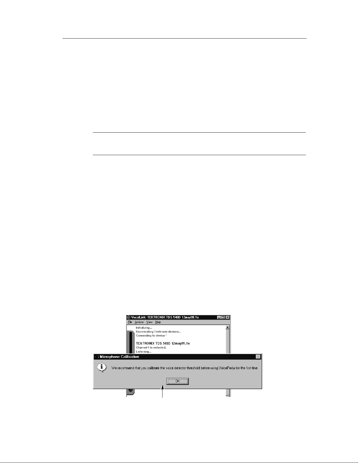
When you launch VocalLink software for the first time, the
Microphone Calibration message box will appear (see Figure 1--1).
Message box
Figure 1- 1: Microphone calibration message
VocalLink Software User Manual
1- 9
Page 22
Getting Started
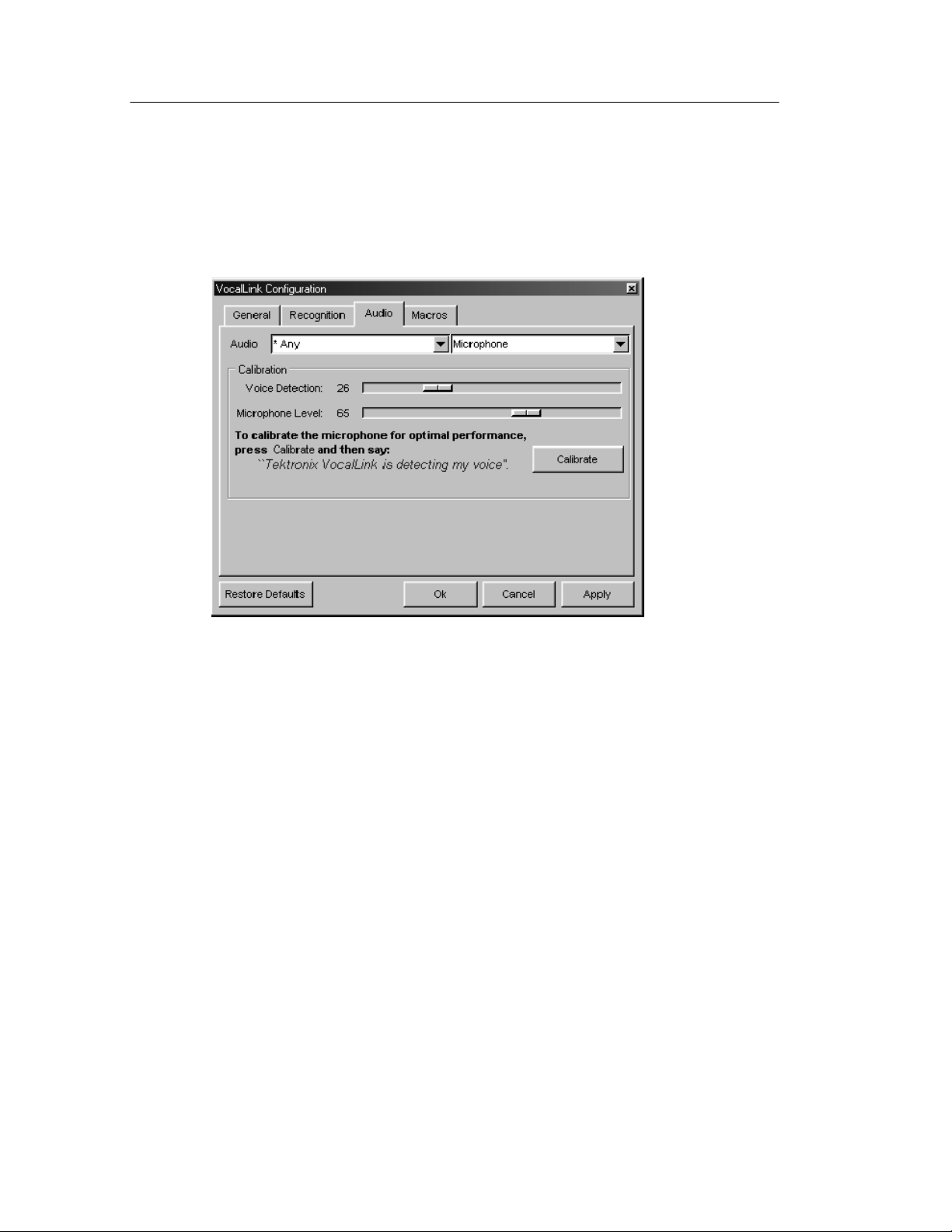
3. Select OK. The Configuration dialog box for the Audio tab is
displayed.
Figure 1- 2: Audio dialog box
4. Put the headset on, and adjust the microphone. The microphone
should be two-finger widths from the corner of your mouth. Refer
to your headset instructions for more details.
5. Follow the bold instructions on the Audio tab (see Figure 1--2) to
calibrate the VocalLink software. Pronounce each word clearly
using normal conversational speech and volume. Select Ok.
1- 10
VocalLink Software User Manual
Page 23

Getting Started
NOTE. When you calibrate the Voice Detection and Microphone
levels, the Windows microphone controls are also automatically
adjusted.
Press the Restore Default button if you want to revert to the default
settings and the Cancel button to recalibrate your voi ce.
If VocalLink requires further calibration, the prompt, “resay the
calibration,” appears up to three times. See troubleshooting on
page 3--14 if you cannot clear this message.
6. You are now ready to say voice commands:
H The voice command set for Basic and Pro is listed on
page 3--1 and in the Help > Commands menu.
Uninstall
To uninstall VocalLink, select the Add/Remove program in the
Microsoft Windows Control Panel . This runs the Uninstall wiz ard,
which takes you through the VocalLink uninstall process.
NOTE. TekVISA must be uninstalled separately.
H To create macro commands see page 2--6.
H For best results, pause before speaking any command.
H If you do not hear any playback when a response for a
measurement is returned, see troubleshooting on page 3--14.
VocalLink Software User Manual
1- 11
Page 24

Getting Started
1- 12
VocalLink Software User Manual
Page 25

Operating Basics
Page 26

Page 27
Operating Basics
This section describes VocalLink software features common to both
the Basic and Pro software, unless stated otherwise.
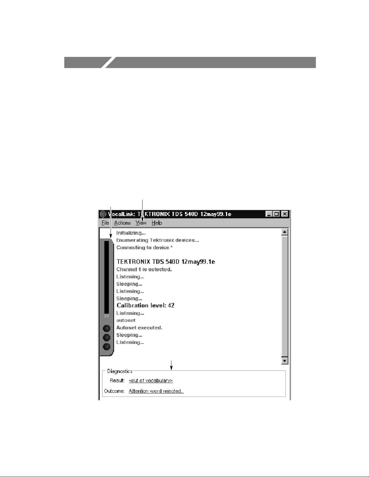
Main Screen Overview
The VocalLink window consists of an indicator bar, a menu bar, a
data window, and a diagnostic window. Figure 2--1 shows each area
of the VocalLink window.
Indicator
bar
Menu bar
(Data Window)
Diagnostics
Window
Figure 2- 1: Main Screen
VocalLink Software User Manual
2- 1
Page 28
Operating Basics
Data Window
The Data window contains a history of your inputs along with the
responses returned from VocalLink software (see Figure 2--1 on
page 2--1). To show or hide the history window, select the
View > Text menu.
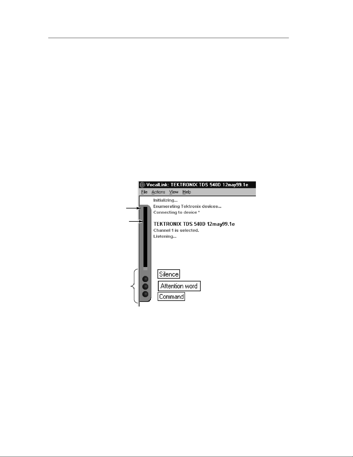
Meter
The meter contains visual information related to voice recognition.
Within the meter are the microphone level gauge and three
recognition lights: Silence, Attention word, and Command (see
Figure 2--2). To show or hide the meter, select the View > Meter
menu.
Meter
Microphone level
indicator:
High voice level
(red)
Low voice level
(green)
Recognition
lights
Figure 2- 2: Meter
Microphone Level. The microphone levels are shown in two colors.
Red is for a high-voice detection level and green a low-voice
detection level.
2- 2
VocalLink Software User Manual
Page 29

There are three flashing recognition lights:
Operating Basics
Recognition lights
Meaning
Silence Flashes green when a sound is
recognized.
Attention word Flashes green or red. Green indi-
cates an attention word* was
recognized and red that the first
sound was not recognized as a
attention word.
Command Flashes green if the command was
recognized and red if the command
was not recognized.
* An attention word activates the voice recognition software
causing it to receive VocalLink commands (see page 3- 9).
Menu Bar
The menu bar contains menus and associated submenus available in
VocalLink (see Figure 2--3). You access the menu bar using standard
Windows menu processes. The menus and submenus are listed in
more detail on page 2--3. To hide the menu bar, select the
View > Menubar menu. To show the menu bar, right select in your
window, and then select the View > Menubar menu. If you do not
have a mouse do not hide the menu bar.
Menu bar
menus
Figure 2- 3: Menu Bar
VocalLink Software User Manual
2- 3
Page 30

Operating Basics
The following table briefly describes the contents of each menu.
Menus
File >
Meaning
Print Opens a dialog box that prints the data
window to the current printer.
Preferences Opens the VocalLink configurations dialog
box with the following tabs:
General: Selects the language, device,
and the speech synthesizer feedback
levels (see page 3--6).
Recognition: Sets the behavior of the
recognition software (see page 3--8).
Audio: Calibrates the microphone and
chooses an audio device (see
page 3--11).
Macro: Lists the macros you create
(see page 3--12).
Exit Exits the VocalLink application and saves all
your settings.
2- 4
Actions >
Listen Toggles the microphone between sleeping
Calibrates
microphone
View > Menubar
Text Window Displays the history text in the Main Window.
Meter Displays the meter in the Main Window.
Diagnostics Displays the diagnostic window in the Main
Always On Top Places the VocalLink application in front of
(microphone ignores all sound) and listening
(identifies command phrases).
Opens the audio dialog box that lets you
calibrate the microphone.
Displays the menu bar in the Main window.
window.
any other application window.
VocalLink Software User Manual
Page 31

Operating Basics
Menus
Help >
Commands Shows a list of all the VocalLink commands
Tuning VocalLink Tuning Tips
About VocalLink VocalLink version
Meaning
Diagnostic Window
The diagnostic window provides command phrase results, voice
playback, and diagnostic information about your spoken command.
To show or hide the diagnostic window, select the View > Diagnostic
menu. The diagnostic window is displayed at the bot tom of the
VocalLink window (see Figure 2--4).
NOTE. The following selections and adjustments for V ocalLink software
have additional tips listed in the Help > Tuning menu.
There are two entries displayed in the diagnostic window: Result and
Outcome. To the right of Result is the result of your spoken
command phrase to VocalLink recognition software. To the right of
Outcome is the decision made by the VocalLink recognition software
about your command phrase.
When you select on the link:
H Result — your spoken command is played back to you
H Outcome — troubleshooting methods are displayed and
explained based on a listed diagnostic feedback. There may be
several possible outcomes for your spoken command phrase.
select here
Figure 2- 4: Diagnostic window
VocalLink Software User Manual
Diagnostic window
2- 5
Page 32

Operating Basics
Creating Macros (Pro Version Only)
Macros allow you to combine multiple commands from the Macro
command set (see page 2--10), plus program sequences of GPIB
command strings (not available for TDS7000), then invoke them
using a voice command. You can use several macros concurrently
and share macros with other users (see Figure 2--5).
Creating a Macro
To create a macro from the available Macro command set, follow
these steps:
1. In the VocalLink Configuration dialog box, open the Macro tab
dialog box (File > Prefere nces menu).
2. Press the New butt on. T he Macro Edi tor window appears.
NOTE. To abandon an editing session, select Cancel at any time.
Macros
Macro
Macro
Macro
Macro
2- 6
Figure 2- 5: Macro dialog box
VocalLink Software User Manual
Page 33

Operating Basics
3. Enter a name for your macro in the Name field (see Figure 2--6).
By default, the macro name is the same as the file name.
Macro
Macro name
Added commands
Numeric entry
box
Command
selection box
with menus
Figure 2- 6: Macro editor dialog box
NOTE. The Macro command set is listed in the left pane of the Macro
Editor window and in this section on page 2--10. The Macro
command set is an equivalent to the voice command set.
VocalLink Software User Manual
2- 7
Page 34

Operating Basics
4. Add a command to the right pane by selecting an available
command twice in the left pane.
If you want to delete a macro command from the right pane,
select that command and press the delete key.
5. Check the box on the left side of the right pane if you want audio
playback (see Figure 2--6).
NOTE. Each command line you enter is numbered in the right pane,
to allow macro control for goto and conditional jumps.
6. After adding macro commands to the right pane, select or enter
the appropriate command values in the selection box menus (see
Figure 2--6). For example, the command to set trigger mode has a
menu that displays auto and normal. You would select one of
these choices.
If a number is needed, enter a number in scientific notation in the
entry box to the right of the command. For example, i f you want
to set the timebase for 2 microseconds, you must enter 2e--6.
7. In the Macro Editor dia log box, select t he Act ion > Validate
Macro menu to check that the macro executes correctly. A
selection box is highlighted if an error is detected (see Fig-
ure 2--7). A description of the error also appea rs under the left
pane. Correct the error, if necessary.
8. To save this macro, select Ok. By default, the macro is enabled
and inserted at the next available macro listing in the Macro
dialog box.
In the Macro dialog box (see Figure 2--5) you can assign a
different number to your new macro. Select your macro name
from the menu in the macro 1 field or in whatever numerical
sequence you prefer.
2- 8
VocalLink Software User Manual
Page 35

Macro
Operating Basics
9. To enable your new macro, use the execute test command and the
macro number. For example say, “Daisy execute test 1.”
NOTE. If the macro is disabled, an error message appears:
macro <n> disabled.
Make sure that your macro is selected in the Macro dialog box (see
macro 1 in Figure 2--5 on page 2--6).
Description of error or
omission
Selected command
line allows playback
Figure 2- 7: Macro command errors
VocalLink Software User Manual
Highlighted box
indicates an error or
omission
2- 9
Page 36

Operating Basics
Table 2- 1: Macro command set
Macro
2- 10
VocalLink Software User Manual
Page 37

Operating Basics
Creating Several Macros
The Export command allows you to save several more macros to a
file. You can display only four macros in the Macro dialog box (see
page 2--6).
1. When you are editing a macro and the Macro Editor window is
open, select the File > Export menu and the Macro File window
appears.
Macro
Enter file name
Figure 2- 8: Export window
2. Enter your file name and select Save.
To open a macro file, select the File > Import menu.
VocalLink Software User Manual
2- 11
Page 38

Operating Basics
Using GPIB and Macro Control Commands
Within the Macro commands set are the GPIB commands and the
Macro Control commands. Brief descriptions of the commands
follow.
GPIB Commands (not available for the TDS 7000)
The GPIB commands are located in the macro command list under
Miscellaneous. Once you place the GPIB command in the right-hand
pane, you can enter a GPIB command string directly into the GPIB
command field.
VocalLink Software does not validate or interpret the GPIB
command string. The line result is the number returned by the GPIB
command. If you selected the GPIB macro command line, you can
activate the GPIB command string to playback the line number (see
Figure 2--7).
Macro command
gpib write This command allows the user to
gpib query This command is similar to the
Definition
enter any valid GPIB command
string.
GPIB write command, except
that this command expects a
string to be returned by the command. This result is printed to
the Main window.
2- 12
VocalLink Software User Manual
Page 39

Operating Basics
Macro Control Commands
The Macro Control commands allow you to change the exec ution of
an instrument setting or measurement. You can use the Macro
Control commands to also set up measurement routines for other
users. A file, called Sample.mac, showing an example using control
commands is provided with your Vocal Link software.
Macro command Definition
goto line This command jumps to either an
available line or the end of the macro.
if result@line condition number goto
line
play prompt This command allows you to record
wait for continue This command allows you to pause
This command allows conditional
jumps that compare two values, and, if
true, allows a jump, or, if false,
executes the next command.
your own spoken instructions. For
example, you can tell the user to move
the probe or speak the name of a
macro.
the execution of a macro until the user
saystheattentionwordfollowedby
continue. For example, “Daisy continue,” causes the macro to continue
execution. The user can use other
voice commands while the program is
waiting for “continue.” Nested macros
are allowed when using this command.
VocalLink Software User Manual
2- 13
Page 40

Operating Basics
2- 14
VocalLink Software User Manual
Page 41

Reference
Page 42

Page 43

Reference
This chapter contains reference information.
H Voice Command Set for both Basic and Pro software
H Configuration dialog boxes
H Troubleshooting guide
V oice Command Set (Basic and Pro Versions)
The following voice command set for Basic and Pro VocalLink
software is also listed in the Help > Commands menu.
You must use an attention word before each command phrase.
You would say the command phrase [Daisy] scale/voltage up [up] as
“Daisy scale up” to increase the scale or “Daisy scale up up” to
increase the scale more.
The attention word [Daisy] can be replaced with other attention
words (see page 3--9). A bracket [ ] indicates an optional word and
a parentheses ( ) indicates you must choose between two or more
words. Not all commands are possible on all oscilloscopes. If a
command is not available an error message is displayed on the main
screen.
VocalLink Software User Manual
3- 1
Page 44

Reference
Table 3- 1: Basic and Pro Voice Command Sets
Vertical
[Daisy] voltage (1/2/5/10/20/50/100/200/500) [pico/nano/micro/milli] volt
[Daisy] scale (1/2/5/10/20/50/100/200/500) [pico/nano/micro/milli] [volt/ampere]
[Daisy] scale up [up]
[Daisy] voltage up [up]
[Daisy] scale down [down]
[Daisy] voltage down [down]
Timebase
[Daisy] get timebase
[Daisy] timebase (1/2/5/10/20/50/100/200/500) [pico/nano/mi c ro/milli] second
[Daisy] timebase up [up]
[Daisy] timebase down [down]
[Daisy] get timebase settings Pro only
[Daisy] (increase/decrease) record length Pro only
Position
[Daisy] position up [up]
[Daisy] position down [down]
[Daisy] position zero
Trigger
[Daisy] get trigger settings
[Daisy] get trigger level
[Daisy] get trigger state
[Daisy] trigger [level] up [up]
3- 2
VocalLink Software User Manual
Page 45

Reference
Table 3- 1: Basic and Pro Voice Command Sets (Cont.)
Trigger
[Daisy] trigger [level] down [down]
[Daisy] trigger [level] zero
[Daisy] trigger level 50 percent
[Daisy] trigger level [minus] (1/2/5/10/20/50/100/200/500 [milli/micro] volt /ampere
[Daisy] trigger slope (fall/rise)
[Daisy] trigger mode (auto/normal)
[Daisy] force trigger
[Daisy] trigger source (channel 1/2/3/4/ auxiliary/ line) Pro only
[Daisy] trigger coupling (AC/DC) Pro only
[Daisy] trigger coupling (high/low frequency) [rejection] Pro only
[Daisy] trigger coupling noise [rejection] Pro only
[Daisy] trigger type edge Pro only
[Daisy] trigger [level] (ECL/TTL) Pro only
Channel
[Daisy] get channel [1/2/3/4] settings
[Daisy] get channel
[Daisy] show channel (1/2/3/4)
[Daisy] hide channel (1/2/3/4)
[Daisy] select channel (1/2/3/4)
VocalLink Software User Manual
3- 3
Page 46

Reference
Channel (Cont.)
[Daisy] channel offset [minus] (0/1/2/ 5/10/20/50/100/200/500) [pico/nano/micro/
milli] [volt/ampere]
[Daisy] coupling (AC/DC/ground)
[Daisy] channel bandwidth (20/100/250/full) [megahertz] Pro only
[Daisy] channel impedance (50 ohm /1 mega ohm) Pro only
[Daisy] channel offset up [up] Pro only
[Daisy] channel offset down [down] Pro only
Measure
[Daisy] (measure/display) peak to peak
[Daisy] (measure/display) frequency
[Daisy] (measure/display) mean
[Daisy] (measure/display) period
[Daisy] (measure/display) RMS
[Daisy] (measure/display) rise time
[Daisy] (measure/display) fall time
[Daisy] (measure/display) positive pulse width
[Daisy] (measure/display) negative pulse width
[Daisy] (measure/display) maximum
[Daisy] (measure/display) minim um
[Daisy] (measure/display) duty cycle
[Daisy] measure snapshot
[Daisy] Remove [all] measurements
3- 4
VocalLink Software User Manual
Page 47

Reference
Acquire
[Daisy] freerun
[Daisy] stop
[Daisy] get acquire (settings/state/mode) Pro only
[Daisy] acquire mode (sample/peak detect/high resolution) Pro only
[Daisy] acquire mode (average/envelope) Pro only
[Daisy] stop after (button/single acquisition)
*
Pro only
[Daisy] repetitive signal (on/off) Pro only
Miscellaneous
[Daisy] autoset
[Daisy] clear menu
[Daisy] hardcopy
[Daisy] save wave
[Daisy] go to sleep
[Daisy] (raise/lower interface)
[
(TDS7000)
[Daisy] initialize Pro only
Macros (Pro)
[Daisy] execute test (1/2/3/4) Pro only
[Daisy] continue Pro only
*
This command sets the acquisition stop after mode to either RUNSTOP
or SEQUENCE.
[
Raise Interface moves the window to the front and Lower Interface
moves the window to the back of all other windows.
VocalLink Software User Manual
3- 5
Page 48

Reference
Configuration Dialog Boxes
There are four Configuration dialog boxes: General, Recognition,
Audio, and Macros.
NOTE. The following selections and adjustments for VocalLink
software have additional tuning tips listed in the Help > Tuning
menu.
General Tab
The General dialog box contains selections and adjustments for
Language, Instrument, and Speech Synthesizer (see Figure 3--1). Use
this dialog box to control the playback behavior. To a ccess the
General tab dialog box, select t he File > Preferences menu.
3- 6
Figure 3- 1: General tab dialog box
VocalLink Software User Manual
Page 49

Reference
Language. You can select the available languages from thi s menu.
Instrument. You can select which instrument VocalLink connects to.
The refresh button updates the list of instruments available through
the VISA interface.
Pitch. You can lower or raise the pitch of the voice playback. The
pitch is measured in Hertz.
Slide right for aSlide left for a
lower pitch higher pitch
Speech Rate. You can change the number of words per minute tha t
the voice synthesizer speaks. The speech rate number is a multiplier;
for example, 2 is twice the natural rate of speech and 0.5 is half the
natural rate.
Slide right for fasterSlide left for slower
speech rate speech rate
VocalLink Software User Manual
3- 7
Page 50

Reference
Recognition Tab
The Recognition dialog box contains selections and adjustments for
the User Level, Attention word, Recognizer, Attention Level, and
Command Level controls. Use this dialog box to change the behavior
of the voice recognition software (see Figure 3--2). To locate the
Recognition tab dialog box select the File > Preferences menu.
NOTE. The following selections and adjustments for Basic and Pro
VocalLink software have additional tuning tips listed in the Help >
Tuning menu.
3- 8
Figure 3- 2: Recognition tab dialog box
VocalLink Software User Manual
Page 51

Reference
User Level. This setting allows a shorter or longer period of silence
at the end of a word before voice recognition occurs. For example, a
novice user will speak slower and need m ore time to respond. If you
are familiar with the software and want shorter pauses and faster
response time, then choose the advanced setting.
User Level Selection Effect
Novice Slower recognition (Default)
Advanced Faster recognition
Attention Words. This menu lists the attention words. Select one or
choose all (*). When all (*) attention words are chosen, then any one
of them can start the beginning of a command phrase.
Daisy TekScope Sally Rosie *(all)
NOTE. If all attention words are enabled voice recognition errors
may increase.
Recognizer. This menu lists voice-recognition engine choices. The
default recognition engine has the fastest performance and requires
the least amount of system resources; therefore, it should be used on
lower performance computers. The other recognition engine
demands increasingly more system resources but is more accurate.
Recognizer selection PC performance
Fastest performance (Default)
Requires less system resources
Best recognition accuracy Require more system resources
VocalLink Software User Manual
3- 9
Page 52

Reference
NOTE. When you load VocalLink, the Attention Level and the
Command Level adjustments are set to defaults.
If you choose to make further adjustment s, it is recommended that
you choose a more precise recognition threshold for attention words
than for command phrases and that you make small adjustments.
Accents and noisy environments can lower optimal performance;
however, set the attention and command levels to as a precise a
setting as is possible.
Attention Level. This slide adjustment controls the recognition
threshold for when an attention word is recognized. For example,
moving the slider to the far left may result in more recognition
errors.
Command Level. This slide adjustment controls the recognition
threshold for when a command phrase is recognized.
For example, moving the slider to the far left may result in
acceptance of inaccurat e c ommand phrases. Moving the slider to the
far right requires you to be more precise when speaking.
Less precise attention
word recognition
Less precise phrase
recognition
More precise attention
word recognition
More precise phrase
recognition
3- 10
VocalLink Software User Manual
Page 53

Reference
Audio Tab
The Audio dialog box contains selections and adjustments for the
Audio, Voice Detection, and Microphone Level controls. Use this
dialog box to calibrate the microphone. To access the Audio tab
dialog box, select the File > Preferences menu.
NOTE. The following selections and adjustments for VocalLink
software have additional tuning tips listed in the Help > Tuning
menu.
Figure 3- 3: Audio tab dialog box
Audio. You may select other sound devices from this menu, if any.
The default is *Any.
Voice Detection. The amplification threshold is automatically set
when you calibrate VocalLink software.
Microphone Level. The recording level is automatically set when
you calibrate VocalLink software.
VocalLink Software User Manual
3- 11
Page 54

Reference
Macros Tab
The Macros dialog box (see Figure 3--4) can display four macros that
you initiate. You can create more than four macros by saving the
macros to a file. See page 2--6 for a list of macro commands and
page 2--10 to create a macro. To access the macros tab dialog box,
select the File > Preferences menu.
Macros
Macros
Macros
Macro
Macro
Macro
Macro
Figure 3- 4: Macro dialog box
Create Macros. This field displays the current ma cro. You can
create a new macro by selecting the New but ton. When your macro
is displayed in the Create Macros field you can edit or delete it by
selecting the Edit or Delete buttons. The Create Macros menu button
lists your macros.
3- 12
Assign Macros. You can display four macros in the Assign Macros
window. Selecting a box to the left of the word macro enables the
macro. By default the file name is the same as the macro name
defined in each macro field. The Macros menu buttons list your
macros.
VocalLink Software User Manual
Page 55

Reference
General Adjustments and Indicators
Review the following information to ensure successful voice
recognition.
Voice Detection Adjustment. After calibrating the VocalLink
software, you may nee d to adjust the Voice Detection level.
If you must speak l ouder for the voice recogn ition to activate:
1. Select the File > Preferences menu
2. In the Audio tab, lower the Voice Detection value by dragging
the slider to the left.
NOTE. The Microphone Level is adjusted only if your Voice Detection
levels are at their highest or lowest values.
For finer playback or voice recognition adjustments, review the
General and Recognition tab dialog boxes on pages 3--6 and 3--8.
Meter. The Meter on the main screen (see page 2--2) displays green
for a softer voice and red for a louder voice. These colors indicate
your voice detection levels. This is another way to determine if your
voice detection values need adjustment.
Speak into the microphone and watch the red and green graphic al
responses to your voi ce on the main screen. Are your graphical
responses mostly red or mostly green?
Green with a flash of red generally indicates a proper voice detection
level. A constant red level indicates the level is too high. For more
information about recognition lights see page 2--3.
VocalLink Software User Manual
3- 13
Page 56

Reference
Troubleshooting VocalLink Problems
This section contains troubleshooting symptoms common to both the
Basic and Pro VocalLink software. Troubleshooting is also available
in your online help the Help > Diagnostics menu.
NOTE. The following selections and adjustments for VocalLink
software have additional tuning tips listed in the Help > Tuning
menu.
Calibration routine warns of bad settings
Possible problems:
H Your microphone is not properly connected (See page 1--4).
H Your sound card is not installed correctly
Quick check. Verify that the sound card and the latest drivers are
installed. See page 1--5.
H Your recording levels are incorrect.
Quick check. Verify tha t the m icrophone is selected in the
recording properties panel. See page 1--5.
You can not hear playback
Possible problems:
H Your speaker or headset is not properly connected.
Quick check. Verify that the microphone is plugged into mic-in
and not line-in. See page 1--4.
H Your sound card is not installed correctly
Quick check. Verify that the sound card and the latest drivers are
installed. See page 1--5.
3- 14
VocalLink Software User Manual
Page 57

H Your playback levels are incorrect:
Quick Check. Verify that the playback volume is not muted in
the Windows playback properties panel.
In Windows, select the Start > Run menu, type sndvol32,
and then ensure that mute is not selected under the Microphone column.
H If you hear a distorted recording:
Your recording level is too high; adjust the recording volume.
VocalLink does not respond when I speak a command
Possible problems:
H Attention and/or command thresholds are too high.
Reference
Quick check. Observe the meter on the main screen to see if the
attention light is flashing green. If it is, then the attention
threshold is set correctly; you may need to adjust the Command
level threshold. If it is not, adjust the attention threshold.
See page 3--10 to adjust rejection thresholds for Attention and
Command levels.
H The speech detector needs calibrating.
See page 1--9 to calibrate the speech detector.
VocalLink Software User Manual
3- 15
Page 58

Reference
VocalLink activates falsely when I am not talking to it
Possible problems:
H Attention thresholds are too low.
See page 3--10 to adjust rejection thresholds for attention levels.
H The speech detector needs calibrating.
See page 1--9 to calibrate the speech detector.
VocalLink recognizes the wrong command
Possible problems:
H Hears too much or too little; the speech detector needs recalibrat-
ing.
See page 1--9, Calibrating speech detector.
H You are speaking the command incorrectly.
See command list on page 3-- 1, or the the Help > Commands
menu.
VocalLink is slow to respond
Possible problems:
H VocalLink does not detect that you have finished speaking right
away; speech detector needs recalibrating.
See page 1--9 to recalibrate the speech detector.
H The User level setting may need to be changed. See page 3--9 to
determine if you are an advanced or novice user.
H Your PC is at or below the minimum requirements (see page 1--2
for a list of requirements).
H There are other programs running or your machine is low on
resources.
3- 16
VocalLink Software User Manual
Page 59

Replaceable Parts List
Page 60

Page 61

Replaceable Parts List
This section contains a list of the replaceable components for the
VocalLink product.
Parts Ordering Information
Replacement parts are available through your local Tektronix field
office or representative.
Changes to Tektronix products are sometimes made to accommodate
improved components as they become available and to give you the
benefit of the latest improvements. Therefore, when ordering parts, it
is important to include the following information in your order:
H Part number
H Instrument type or model number
H Instrument serial number
H Instrument modification number, if applicable
If you order a part that has been replaced with a different or
improved part, your local Tektronix field office or representative will
contact you concerning any change in part number.
Using the Replaceable Parts List
The tabular information in the Replaceable Parts List is arranged for
quick retrieval. Following is a brief description of the columns.
H Column 1, Tektronix part number
H Column 2, Quantity
H Column 3, Name and description
H Column 4, Mfr. code is the name of the actual manufacturer.
H Column 5, Manufacturer or vender part number.
VocalLink Software User Manual
4- 1
Page 62

Replaceable Parts List
Abbreviations
Abbreviations conform to American Nati onal Standard ANSI
Y1.1--1972.
Mfr. Code to Manufacturer Cross Index
The table titled Manufacturers Cross Index shows codes, names, and
addresses of manufacturers or vendors of components listed in the
parts list.
Manufacturers cross index
Mfr.
code Manufacturer Address
80009 TEKTRONIX INC 14150 SW KARL BRAUN DR
PO BOX 500
TK2548 XEROX CORPORATION 14181 SW MILLIKAN WAY BEAVERTON, OR
TK6108
KENT H LANDSBERG CO 27929 SW 95TH, SUITE 101 WILSONVILLE,
City, state, zip
code
BEAVERTON, OR
97077--0001
97005
OR 97070
Replaceable electrical parts list
Tektronix
part number
071--0824--01 1 MANUAL,TECH:USER,VCLNKB TK2548 071--0824-- 01
116--1007-- 00 1 HEADSET TK6108 116--1007--00
Qty Name & description
Mfr.
code
Mfr. part
number
4- 2
VocalLink Software User Manual
Page 63

Appendices
Page 64

Page 65

Appendix A: RS-232
This section provides instructions to set the default RS-232 values on
various Tektronix oscilloscopes and some general troubleshooting
help.
Setting RS-232 Default Values
Refer to the following information for RS-232 interface connections
for your specific oscilloscope family.
TDS 3000 Series Oscilloscopes
If you are using a TDS 3000 Serie s oscilloscope, you can use the Set
RS-232 Parameters to Default Values button to set the RS-232
settings on the oscilloscope to the default values.
Follow the steps below to access the Set RS232 Parameters to
Defaults button.
1. Push the Utility button on the oscilloscope.
2. Push the bottom left bezel button (System Config) on the
oscilloscope repeatedly until I/O is selected.
3. Select RS-232.
4. Push the fifth bezel button on the oscilloscope (labeled Set RS232
Parameters to Default).
You can examine the Error Log for clues about your RS-232
interface connection. Follow the steps below to access the Error Log:
1. Push the Utility button on the oscilloscope.
2. Push the bottom left bezel button on the oscilloscope repeatedly
until Diag is selected.
VocalLink Software User Manual
A- 1
Page 66

Appendix A: RS-232
3. Push the bezel button on the oscilloscope labeled Error Log.
Check the lines in the Error Log titled RS-232 Line Snapshot and
RS-232 Errors. Refer to the programmer manual for your oscilloscope for information about interpreting the information in the Error
Log.
TDS500, TDS600, and TDS700 Series
The TDS500, TDS600, and TDS700 Series oscilloscopes may
support RS-232 printers but c annot be controlled over the RS-232
interface. VocalLink Software can only communicate with these
series of oscilloscopes using a GPIB interface connection.
RS-232 General Hints
H Make sure the communication parameters are set correctly on the
oscilloscope. Baud rates should be the same, Parity should be
None, Data Bits should be 8, and Stop Bits should be 1.
Soft flagging should never be used for waveform and hardcopy
transfers. This is because waveform data and hardcopy output
contain binary characters which can easily include the XON and
XOFF characters used to implement soft flagging. Soft flagging
should only be used for transferring stored setups since stored
setup information generally consists of printable ASCII text.
H Although it generally should not matter if the EOL characters are
the same, set the EOL to CRLF to be sure there are no problems.
A- 2
VocalLink Software User Manual
Page 67

Appendix A: RS-232
H Not all instruments support full RS-232 communications. Some
instruments only support GPIB c ommunication, while others
support limited RS-232 functions, such as printer functions.
H If you are able to connect to an instrument but unable to transfer
waveforms successfully, you may have a cable that is not wired
correctly for hard flagging.
If you can successfully transfer settings to and from the
instrument at the fastest supported baud rate, hard flagging is
probably working. If not, try soft flagging. If you can successfully
transfer settings using soft flagging but not with ha rd fla gging,
there is a good chance the hard flagging li nes of your cable are
not connected properly.
RS-232 Cable Issues
If the information provided so far in this section fails to resolve your
RS-232 problems, try the following information:
H You might be using an incompatible RS-232 cable. There is no
such thing as a standard RS-232 cable , so you may need to use an
ohmmeter to verify that your cable is wired correctly. Many
cables do not have all of the pins connected.
H Determine whether the PC and oscilloscope are DTE (Data
Terminal Equipment) or DCE (Data Communications Equipment)
devices. This information is in the documentation provided with
your oscilloscope and with your PC.
VocalLink Software User Manual
A- 3
Page 68

Appendix A: RS-232
H If you are connecting a DTE device to a DCE device you will
need a straight-through cable. This is a cable that has the same
pin assignments on both ends of the cable.
H If you are connecting two devices of the same type, you need a
null modem cable. This is a cable whose lines are crossed such
that the inputs of one device are connected to the outputs of the
other.
CAUTION. Do not connect the output lines of two same-type devices
to each other. Doing so will damage one or both of the devices.
H For hard flagging to work, the RTS (Request To Send) and CTS
(Clear To Send) lines must be connected. Use an ohmmeter to
verify that they are actually connected since not all cables
connect these lines. The RTS line is sometimes referred to as
RFR.
H The DCD (Data Carrier Detect) line is not used by VocalLink so
it does not matter whether or not it is c onnected. The DCD line i s
sometimes referred to as RLSD.
A- 4
VocalLink Software User Manual
Page 69

RS-232 Cable Examples
The information in this section provides correct wiring and pin
assignments for RS-232 interface connections with each type of
oscilloscope.
TDS3000 Series Oscilloscope to PC (DB9 to DB9 )
Table A--1 lists the correct wiring for connecting a TDS3000 Series
oscilloscope with 9 pins to a 9 pin serial port on a DTE PC. These
oscilloscopes are DTE devices.
Table A- 1: Pin assignments for TDS3000 Series oscilloscopes (DB9 to
DB9)
Appendix A: RS-232
DB9
connector pin
number (to
TDS line
(RxD) 2 3 (TxD)
(TxD) 3 2 (RxD)
(DTR) 4 6 (DSR)
(GND) 5 5 (GND)
(DSR) 6 4 (DTR)
(RTS) 7 1, 8
(CTS) 8 7 (RTS)
1
Pins 1 and 8 are wired together.
oscilloscope)
DB9
connector
pin number
(to PC)
1
DB9 signal name
(CTS)
VocalLink Software User Manual
A- 5
Page 70

Appendix A: RS-232
Connecting Two Like Devices (DCE to DCE or DTE to DTE)
Using Null Modem Cable
Table A--2 lists the correct wiring for connecting two like devices
together using a DB25 female to DB25 female cable.
Table A- 2: Pin assignments for DB25 Female to DB25 Female Null
Modem Cable
DB25female25pin
connector
Chassis Ground 1 1 Chassis Ground
(TxD) 2 3 (RxD)
DB25
female pin
number
PC pin Line name
(RxD) 3 2 (TxD)
(RTS) 4 5 (CTS)
(CTS) 5 4 (RTS)
(DSR DCD) 6,8
(DTR) 20 6,8
(Signal GND) 7 7 (Signal GND)
1
Pins 6 and 8 are wired together.
1
20 (DTR)
1
(DCR DCD)
A- 6
VocalLink Software User Manual
Page 71

Appendix B: GPIB
Most GPIB problems are caused by general errors. Table B--1 lists
common GPIB problems.
T able B- 1: Common GPIB Errors
Problem Solution
Loose cable Make sure cables are securely connected to both
Wrong GPIB address Make sure you have selected the correct address.
the PC and the oscilloscope.
Verify the GPIB address of your instrument. The
address is an instrument function, so refer to your
instrument user manual for instructions on how to
check and set the instrument’s GPIB address.
Multiple devices using
the same GPIB address
Timeout value too slow Set the timeout value to a faster time.
Windows GPIB Drivers
not Installed
Old version of GPIB
drivers
Make sure each instrument connected to the GPIB
bus has a unique GPIB address.
Install the proper Windows GPIB drivers.
If possible, obtain and install the latest drivers from
your GPIB manufacturer. Many manufactures have
a web site containing their latest drivers.
VocalLink Software User Manual
B- 1
Page 72

Appendix B: GPIB
If you experience problems using GPIB com munication, use the
steps below to try to resolve the proble m. Usually, proble ms have a
simple cause such as an incorrect address or faulty cable. If the
procedures below or other GPIB-related help information does not
fix the problem, contact Tektronix Technical Support for further
help. See page vii for information on how to contact Tektronix.
First, make sure you are using the proper equipment to establish the
GPIB connection:
H GPIB Interface card (IEEE Std 488.2) Version C.12 or later
H GPIB Cable
After verifying you are using the proper GPIB equipment, follow the
steps below.
1. Disconnect all GPIB cables from the PC.
2. Run the hardware diagnostics supplied with the GPIB card.
3. Run the software diagnostics supplied with the card.
4. If the GPIB diagnostics fail, or if you have difficulty running
them, contact the technical support of the card manufacturer.
5. If the GPIB diagnostics pass, contact Tektronix.
B- 2
VocalLink Software User Manual
Page 73

Appendix C: TekVISA
Appendix C provides information about VISA files, and how to
configure the TekVISA utility when using AD007 GPIB-LAN or
TDS3EM communication modules.
Choosing a VISA File
TekVISA is the Tektronix version of VISA software. Typical ly, only
one version of VISA (Visa32.dll file ) is located in your C:/windows/
system at a time. If you have another company’s VISA on your
system, then you must choose between TekVISA and that other
VISA. VocalLink software will only use a VISA file called
Visa32.dll.
To choose between TekVISA and another VISA, you will need to
consider further information. Choosing a VISA File, will help you
with this decision.
If you decide to have two VISA files, Managing Two VISA Files (see
page C--2) will guide you through the renaming process for these
VISA files.
If you choose to overwrite the existing Visa32.dll file, the installation
process will delete any other Visa32.dll file in your System directory
of Windows and replace it with the TekVISA Visa32.dll file.
NOTE. Review the following information when choosing between
TekVISA and another company’s VISA.
H The AD007 GPIB-LAN Adapter and the Tektronix TDS3EM
requires TekVISA.
H The VocalLink software may work with a VISA from another
company, provided their VISA software supports the int erface
types with which you are working. If you choose to use a VISA
from another company and find it does not work with the
VocalLink Software User Manual
C- 1
Page 74

Appendix C: TekVISA
VocalLink software, you can install TekVISA later using the
VocalLink installer.
H TekVISA does not support VXI Mainframe communication.
Managing Two VISA Files
To keep two different VISA files, you will need to rename the
existing VISA file and then copy the other VISA file you want to use
to your system.
In the following example, you have t wo VISA files (one is from
National Instruments, one is TekVISA), and the current VISA file is
the National Instruments (NI).
To overwrite the NI VISA file, follow these steps:
1. Rename the NI VISA file to Visa32_ni.dll
2. Copy the TekVISA Visa32.dll file into the Window’s System
directory.
VocalLink can now use the TekVISA Visa32.dll file.
Configuring TekVISA for AD007 GPIB-LAN or TDS3EM
Check that your instrument is connected to the LAN and is assigned
a valid IP address. If you do not know the IP address check with your
network administrator.
Follow the steps below to add the IP address of the instrument to the
TekVISA configuration program.
1. Select Start > Programs > TekVISA > VISA Configuration to run
the TekVISA configuration program. The program will take a few
moments to locate current resources.
2. Select the Add button in the Remote Hosts pane to open the Add
Remote Host dialog box.
3. Enter the IP address of your instrument in the Host Name field.
For example, 128.23.304.45. Do not enter or change the values in
the other fields.
C- 2
VocalLink Software User Manual
Page 75

Appendix C: TekVISA
4. Select the OK button. The configuration program closes the Add
Remote Host dialog box and searches the LAN for the specified
address.
5. The configuration program updates the TekVISA Configuration
dialog box with the VISA resource for the newly-added
instrument.
NOTE. The VISA Configuration program labels Ethernet and GPIB
resources as GPIBx::x::xxx; this is OK. The RS--232 resources are
labeled as ASRL::INSTR
6. If the VISA Configuration program does not locate your
instrument, verify with the network administrator that:
H The instrument has a valid IP address
H The instrument IP address is loaded into the instrument.
H The instrument is powered on and connected to the LAN.
VocalLink Software User Manual
C- 3
Page 76

Appendix C: TekVISA
C- 4
VocalLink Software User Manual
Page 77

Index
Page 78

Page 79

Index
A
About this manual set, v
Accents, 3--10
Actions menu
calibrates microphone, 2--4
listen, 2--4
AD007 GPIB--LAN, 1--3
Address, Tektronix, vii
Attention level, 3--10
Attention word, 3--9
Audio tab
calibrate the microphone, 3--11
microphone level, 3--11
select sound card, 3--11
voice detection, 3--11
B
Basic, installing, 1--6
C
Calibrates microphone, 1--9, 2--4
Command level, 3 --10
Command set
Macro(Pro),2--10
voice, 3--1
Configuration dialog boxes
audio, 3--11
general tab, 3--6
Macro(Pro),3--12
recognition tab, 3--8
Contacting Tektronix, vii
D
Default RS--232 parameter, settings
for the TDS 3000 series, A--1
Diagnostic window, troubleshoot-
ing, 2--5
Diagnostics, online, 2--5
F
File menu
preferences, 2--4
print, 2--4
G
General tab
languages, 3--7
pitch, 3--7
speech rate, 3--7
GPIB
common errors, B--1
National Instruments, 1--3
resolving problems, B --2
gpib commands, write, query, 2--12
H
Headset, connect, 1--4
Help menu
commands, 2--5
readme, 2--5
VocalLink Software User Manual
Index- 1
Page 80

Index
I
Installing
basic, 1--6
keycode, 1--6
Pro, 1--6
TekV ISA, 1 -- 7
Instrument, 3--7
K
Keycode
for installation, vi
installation, 1--6
L
Languages, 3--7
Microphone, calibration, 1--9
Microphone level, 3--11
N
National Instruments, IEEE inter-
face card, 1--3
P
Phone number, Tektronix, vii
Pitch, 3--7
Pro, installation, 1--6
Pro and Basic version, voice com-
mand set, 3 --1
Product support, contact informa-
tion, vii
M
Macro (Pro), control commands,
2-- 13
Macro (Pro) command set, 2--10
Macro (Pro) control commands,
2-- 13
Macro tab
assign Macro, 3--12
create Macro, 3--12
Macro tab (Pro), dialog box, 3--12
Main screen
data window, 2--2
menu bar, 2--3
meter, 2--2
microphone Level, 2--2
overview, 2--1
Manual, how to use the set, vi
Menu bar, 2--3
R
Recognition engines, 3--9
Recognition lights, meanings , 2--3
Recognition tab
accents, 3--10
attention level, 3--10
attention words, 3--9
command level, 3--10
noisy environments, 3 --10
recognizer engines, 3--9
user level, 3--9
Registration card, vi
Requirements, system, 1 -- 2
RS-232
cable examples by product fami-
ly, A--5
cable issues, A--3
default values, 1--3
Index- 2
VocalLink Software User Manual
Page 81

Index
S
Service support, contact informa-
tion, vii
Software license, vi
Sound Card
checking for a sound card, 1--5
test recording and playback, 1--5
Speech rate, 3--7
System requirements, 1--2
T
TDS 3000 series, RS-232 connec-
tion, A--1
TDS 500 series, RS-232 connec-
tion, A--2
TDS 600 series, RS-232 connec-
tion, A--2
TDS 700 series, RS-232 connec-
tion, A--2
TDS3EM ethernet module, 1--3
Technical s upport, contact informa-
tion, vii
TekVISA, 1 --3, C--1
installation, 1--7
switching Visa32.dll files, C--1
Test (Pro)
creating, 2--6
errors, 2--9
exporting, 2--11
gpib commands, 2 --12
importing, 2--11
Troubleshooting
online diagnostics, 2--5
RS--232 cable issues, A--3
RS--232 general hints, A--2
VocalLink problems, 3 --14
U
Uninstalling, 1--11
URL, Tektronix, vii
User Levels, 3--9
V
View menu
always on top, 2--4
diagnostics, 2--4
menubar, 2--4
meter, 2--4
text window, 2--4
VISA, C--1
Visa32.dll files, C--1
VocalLink software, general adjust-
ments, 3--13
Voice command set, Pro and Basic
version, 3--1
Voice detection, 3--11
W
Web site address, Tektronix, vii
VocalLink Software User Manual
Index- 3
Page 82

Index
Index- 4
VocalLink Software User Manual
 Loading...