

Tektronix Using Keithley DriverLINX with the KPCI-3140 Board (from DOCS-850A13) (0.5 Mb) User manual

Keithley KPCI-3140 Series

Information in this document is subject to change without notice. T he software
described is this document is furnished under a license agreement. The software may
be used or copied only in accordance with the terms of the agreement.
SCIENTIFIC SOFTWARE TOOLS, INC. SHALL NOT BE LIABLE FOR ANY
SPECIAL, INCIDENTAL, OR CONSEQUENTIAL DAMAGES RELATED TO
THE USE OF THIS PRODUCT. THIS PRODUCT IS NOT DESIGNED WITH
COMPONENTS OF A LEVEL OF RELIABILITY SUITABLE FOR USE IN LIFE
SUPPORT OR CRITICAL APP LICATIONS.
This document may not, in whole or in part, be copied, photocopied, reproduced,
translated or reduced to any electronic medium or machine readable form without
prior written consent from Scientific Software Tools, Inc.
Keithley KPCI-3140 Series: Using DriverLINX with Your Hardware
Copyright 2000 by Scientific Software Tools, Inc.
All rights reserved.
First Printing.
SST 28-0100-3
DriverLINX, SSTNET, and LabOBJX are registered trademarks and
DriverLINX/VB is a trademark of Scientific Software Tools, Inc.
MetraByte is a trademark of Keithley Instruments, Inc.
Microsoft and Windows are registered trademarks and Visual C++ and Visual Basic
are trademarks of Microsoft Corporation.
Borland is a registered trademark and Borland C++ and Delphi are trademarks of
Borland International, Inc.
All other brand and product names are trademarks or registered trademarks of their
respective companies.

Contents
Preface 5
Software License and Software Disclaimer of Warranty...........................................................5
About DriverLINX.....................................................................................................................7
About This User’s Guide...........................................................................................................7
Conventions Used in This Manual.............................................................................................9
Configuring the KPCI-3140 Series 11
Introduction..............................................................................................................................11
Configure DriverLINX Device Dialog ....................................................................................12
Using the KPCI-3140 Series with DriverLINX 19
Introduction..............................................................................................................................19
KPCI-3140 Series Hardware Features.....................................................................................19
DriverLINX Hardware Model for KPCI-3140 Series..............................................................20
Connecting Signals to the KPCI-3140 Series ..........................................................................24
Device Subsystem....................................................................................................................28
Digital Input Subsystem...........................................................................................................29
Digital Output Subsystem........................................................................................................44
Device Subsystem Page.............................................................................................13
Digital Input Subsystem Page....................................................................................14
Digital Output Subsystem Page.................................................................................16
Counter/Timer Subsystem Page.................................................................................18
DriverLINX Subsystems............................................................................................20
DriverLINX Modes ...................................................................................................20
DriverLINX Operations and Events..........................................................................22
Logical Channels.......................................................................................................23
Buffers.......................................................................................................................23
Digital Input Subsystem Signals................................................................................24
Digital Output Subsystem Signals.............................................................................26
Counter/Timer Subsystem Signals.............................................................................26
Device Modes............................................................................................................28
Device Operations .....................................................................................................28
Digital Input Modes...................................................................................................29
Digital Input Operations............................................................................................29
Digital Input Timing Events......................................................................................30
Digital Input Start Events ..........................................................................................34
Digital Input Stop Events...........................................................................................35
Digital Input Channels...............................................................................................38
Digital Input Buffers..................................................................................................41
Digital Input Messages..............................................................................................43
Digital Output Modes................................................................................................44
Digital Output Operations..........................................................................................44
Digital Output Timing Events....................................................................................45
Using DriverLINX with Your Keithley KPCI-3140 Series Contents • 3

Digital Output Start Events........................................................................................50
Digital Output Stop Events........................................................................................51
Digital Output Channels ............................................................................................54
Digital Output Buffers...............................................................................................57
Digital Output Messages............................................................................................58
Counter/Timer Subsystem........................................................................................................59
Counter/Timer Channel Usage...................................................................................60
Clock Sources and Modes..........................................................................................60
Gate Settings..............................................................................................................62
Counter/Timer Tasks .................................................................................................62
Counter/Timer Messages...........................................................................................64
Uninstalling DriverLINX 65
How do I uninstall DriverLINX?.............................................................................................65
Troubleshooting 69
Solving Problems.....................................................................................................................69
Solving Problems Recognizing and Installing Drivers..............................................69
Solving Problems Configuring the Drivers................................................................70
Solving Problems Loading Drivers............................................................................70
Generating a DriverLINX Configuration Report..................................................................... 73
What is in the Report? ...............................................................................................73
How do I Generate the Report? .................................................................................73

Preface
Software License and Software Disclaimer of Warranty
This is a legal document which is an agreement between you, the Licensee, and Scientific Software Tools, Inc. By opening this
sealed diskette package, Licensee agrees to become bound by the terms of this Agreement, which i nclude the Software License and
Software Disclaimer of Warranty.
This Agreement constitutes the complete Agreement between Licensee and Scientific Software Tools, Inc. If Licensee does not
agree to the terms of this Agreement, do not open the diskette package. Promptly return the unopened diskette package and the other
items (including written materials, binders or other containers, and hardware, if any) that are part of this product to Scientific Software
Tools, Inc. for a full refund. No refunds will be given for products that have opened disk packages or missing components.
Licensing Agreement
Copyright. The software and documentation is owned by Scientific Software Tools, Inc. and is protected by both United States
copyright laws and international treaty provisions. Scientific Software Tools, Inc. authorizes the original purchaser only (Licensee) to
either (a) make one copy of the software solely for backup or archival purposes, or (b) transfer the software to a s ingle hard disk only.
The written materials accompanying the software may not be duplicated or copied for any reason.
Trade Secret. Licensee understands and agrees that the software is the proprietary and confidential property of Scientific Software
Tools, Inc. and a valuable trade secret. Licensee agrees to use the software only for the intended use under this License, and shall not
disclose the software or its contents to any third party.
Copy Restrictions. The Licensee may not modify or translate the program or related documentation without the prior written
consent of Scientific Software Tools, Inc. All modifications, adaptations, and merged portions of the software constitute the software
licensed to the Licensee, and the terms and conditions of this agreement apply to same. Licensee may not distribute copies, including
electronic transfer of copies, of the modified, adapted or merged software or accompanying written materials to others. Lic ensee agrees
not to reverse engineer, decompile or disassemble any part of the software.
Unauthorized copying of the software, including software that has been modified, merged, or included with other soft ware, or of the
written materials is expressly forbidden. Licensee may not rent, transfer or lease the software t o any third parties. Licensee agrees to
take all reasonable steps to protect Scientific Software Tools’ software from theft, disclosure or use contrary to the terms of the License.
License. Scientific Software Tools, Inc. grants the Licensee only a non-exclusive right to use the serialized copy of the software on a
single terminal connected to a single computer. The Licensee may not network the software or use it on more than one computer or
computer terminal at the same time.
Term. This License is effectiv e until terminated. This License will terminate automatically without notice from Scientific Software
Tools, Inc. if Licensee fails to comply with any term or condition of this License. The Licensee agrees upon such termination to return or
destroy the written materials and all copies of the software. The Licensee may terminate the agreement by returning or dest roying the
program and documentation and all copies thereof.
Using DriverLINX with Your Keithley KPCI-3140 Series Preface • 5

Limited Warranty
Scientific Software Tools, Inc. warrants that the software will perform substantially in accordance with the written materials and that
the program disk, instructional manuals and reference materials are free from defects in materials and workmanship under normal use for
90 days from the date of receipt. All express or implied warranties of the software and related materials are limited to 90 days.
Except as specifically set forth herein, the software and accompanying writt en materials (including i nstructions f or use) are provided
“as is” without warranty of any kind. Further, Scientific Software Tools, Inc. does not warrant, guarantee, or make any representa tions
regarding the use, or the results of the use, of the software or written materials in terms of correctness, accuracy , reliabil ity, current ness,
or otherwise. The entire risk as to the results and performance of the software is assumed by Licensee and not by Scientific Softwa re
Tools, Inc. or its distributors, agents or employees.
EXCEPT AS SET FORTH HEREIN, THERE ARE NO OT HER WARRANTIES, EITHER E XPRESS OR IMPL IED, I NCLUDING BUT
NOT LIMITED TO IMPLIED WARRANTIES OF MERCHANTABILITY AND FITNESS FOR A PARTICULAR PURPOSE, WITH
RESPECT TO THE SOFTWARE, THE ACCOMPANYING WRITTE N MATERIALS, AND ANY ACCOMPANYING HARDWARE.
Remedy. Scientific Software Tools’ entire liability and the Licensee’s exclusive remedy shall be, at Scientific Software Tools’ option,
either (a) return of the price paid or (b) repair or replacement of the software or accompanying materials. In the event of a defect in
material or workmanship, the item may be returned within the warranty period to Scientific Software Tools for a replacement without
charge, provided the licensee previously sent in the limited warranty registrat ion board to Scientific Software Tools, Inc., or can furnish
proof of the purchase of the program. This remedy is void if failure has resulted from accident, abuse, or misapplication. Any replacement
will be warranted for the remainder of the original warranty period.
NEITHER SCIENTIFIC SOFTWARE TOOLS, INC. NOR ANYONE ELSE WHO HAS BEEN INVOLVED IN THE CREATION,
PRODUCTION, SALE OR DELIVERY OF THIS PRODUCT SHALL BE LIABLE FOR ANY DIRECT, INDI RECT, CONSEQUENTIAL,
OR INCIDENTAL DAMAGES (INCLUDING DAMAGES FO R LOSS OF BUSINES S PROFI TS, BUSI NESS IN TERRUPTI ON, LOSS OF
BUSINESS INFORMATION AND THE LIKE) ARISING OUT OF THE USE OF OR THE INABILITY TO USE SUCH PRODUCT EVEN IF
SCIENTIFIC SOFTWARE TOOLS HAS BEEN ADVISED OF THE POSSIBILITY OF SUCH DAMAGES. BECAUSE SOME
JURISDICTIONS DO NOT ALLOW THE EXCLUSION OR LIMITATION OF LIABILITY FOR CONSEQUENTIAL OR INCIDENTAL
DAMAGES, OR LIMITATIONS ON DURATION OF AN IMPLIED WARRANTY, THE ABOVE LIMITATIONS MAY NOT APPLY TO
LICENSEE.
This agreement is governed by the laws of the Commonwealth of Pennsylvania.
6 • Preface Using DriverLINX with Your Keithley KPCI-3140 Series

About DriverLINX
Welcome to DriverLINX for Microsoft Windows, the high-performance realtime data-acquisition device drivers for Windo ws application development.
DriverLINX is a language- and hardware-independent application programming
interface designed to support hardware manufacturers’ high-speed analog, digital,
and counter/timer data-acquisition boards in Windows. DriverLINX is a multi-user
and multitasking data-acquisition resource manager providing more than 100
services for foreground and background data acquisition tasks.
Included with your DriverLINX package are the following items:
• The DriverLINX API DLLs and drivers supporting your data-
acquisition hardware
• Analog I/O Panel, a DriverLINX program that verifies the installation
and configuration of DriverLINX for your analog input/output board
and demonstrates several virtual bench-top instruments
• Source code for the sample programs
• The DriverLINX Application Programming Interface files for your
compiler
• DriverLINX On-line Help System
• DriverLINX Analog I/O Programming Guide
• DriverLINX Digital I/O Programming Guide
• DriverLINX Counter/Timer Programming Guide
• DriverLINX Technical Reference Manual
• Supplemental Documentation on DriverLINX and your data-
acquisition hardware
About This User’s Guide
The purpose of this manual is to help you quickly learn how to configure and use the
hardware features of Keithley’s KPCI-3140 Series boards with DriverLINX.
• For help installing and configuring your hardware and DriverLIN X,
please see the manual that accompanied your hardware.
• For more information on the DriverLINX API, please see the
DriverLINX Technical Reference Manual.
• For additional help programming your board, please examine the
source code examples on the Distribution Disks.
This manual contains the following chapters:
Configuring the KPCI-3140 Series
Shows how to configure the KPCI-3140 Series using the Configure DriverLINX
Device dialog box.
Using the KPCI-3140 Series with DriverLINX
Using DriverLINX with Your Keithley KPCI-3140 Series Preface • 7

Shows how to set up DriverLINX with the Edit Service Request dialog box to use
KPCI-3140 Series hardware features.
Uninstalling DriverLINX
Describes how to remove DriverLINX hardware drivers and other files.
Troubleshooting
Gives troubleshooting tips for insta lling, conf i guring, and loading DriverLINX
drivers.
8 • Preface Using DriverLINX with Your Keithley KPCI-3140 Series

Conventions Used in This Manual
The following notational conventions are used in this manual:
• A round bullet (•) identifies itemized lists.
• Numbered lists indicate a step-by-step procedure.
• DriverLINX Application Programming Interface and Windows macro
and function names are set in bold when mentioned in the text.
• DriverLINX indicates the exported function name of the device driver
DLL while DriverLINX indicates the product as a whole.
• DriverLINX Application Programming Interface identifiers, menu
items, and Dialog Box names are italicized when mentioned in the text.
• Italics are used for emphasis.
• Source code and data structure examples are displayed in Courier
typeface and bounded by a box with a single line.
Code
• A box with a double line bound tables of information.
Table
Concept
• Important concepts and notes are printed in the left margin.
Using DriverLINX with Your Keithley KPCI-3140 Series Preface • 9


Configuring the KPCI-3140 Series
Introduction
The installation program provides general instructions for installing and configuring
DriverLINX. This manual explains the steps and special features that apply to
Keithley’s KPCI-3140 Series boards.
Installing and configuring DriverLINX for a Keithley KPCI-3140 Series board
requires three steps:
1. Install DriverLINX. Follow the instruct ions given by the installation
program. The Read Me First instructions explain the components and
drivers you can install.
2. Configure DriverLINX. This creates a Logical Device, which stores
configuration information for your board. See “Configure DriverLINX
Device Dialog” on page 12 for configuration options specific to a
Keithley KPCI-3140 Series model.
Windows NT
3. Install your KPCI-3140 hardware. Follow the instructions in your
hardware man ua l.
After configuring DriverLINX, insta l ling your b oard and rest arting Windo ws, reopen
the DriverLINX Configuration Panel to make sure that DriverLINX loaded the
Logical Device for your board. If the Logical Device is not loaded, the Event Log
may have a message from the driver that explains why. You can check the Event Log
using the DriverLINX Event Viewer on the Windows Start Menu.
Under Windows NT 4.0, a Logical Device may not load because the operating
system does not always configure Plug-and-Play PCI devices properly. To work
around this , set your computer’s BIOS to config ure Plug-and-Play devices before it
starts the operating system. On various computers the BIOS setting is called “Plugand-Play Aware OS – Disabled” or “Plug & Play OS – No”.
Using DriverLINX with Your Keithley KPCI-3140 Series Configuring the KPCI-3140 Series • 11
Configure DriverLINX Device Dialog
DriverLINX uses a standardized configuration protocol for all data-acquisitio n
hardware. Configuration assigns an identifying device number to a specific KPCI3140 Series board in your computer and allows you to enable or disable bus
mastering.
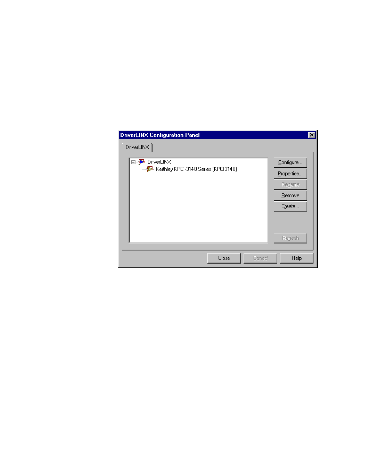
The installation program automatically starts the DriverLINX Configuration Panel.
To start it now, use the shortcut on the Windows Start Menu.
When you click the Configure… button on the DriverLINX Configuration Panel,
DriverLINX displays the Configure DriverLINX Device dialog. The dialog has a
page for each subsystem on the Keithley KPCI-3140 Series. The following sections
describe your choices in configuring DriverLINX to work with your board.
12 • Configuring the KPCI-3140 Series Using DriverLINX with Your Keithley KPCI-3140 Series
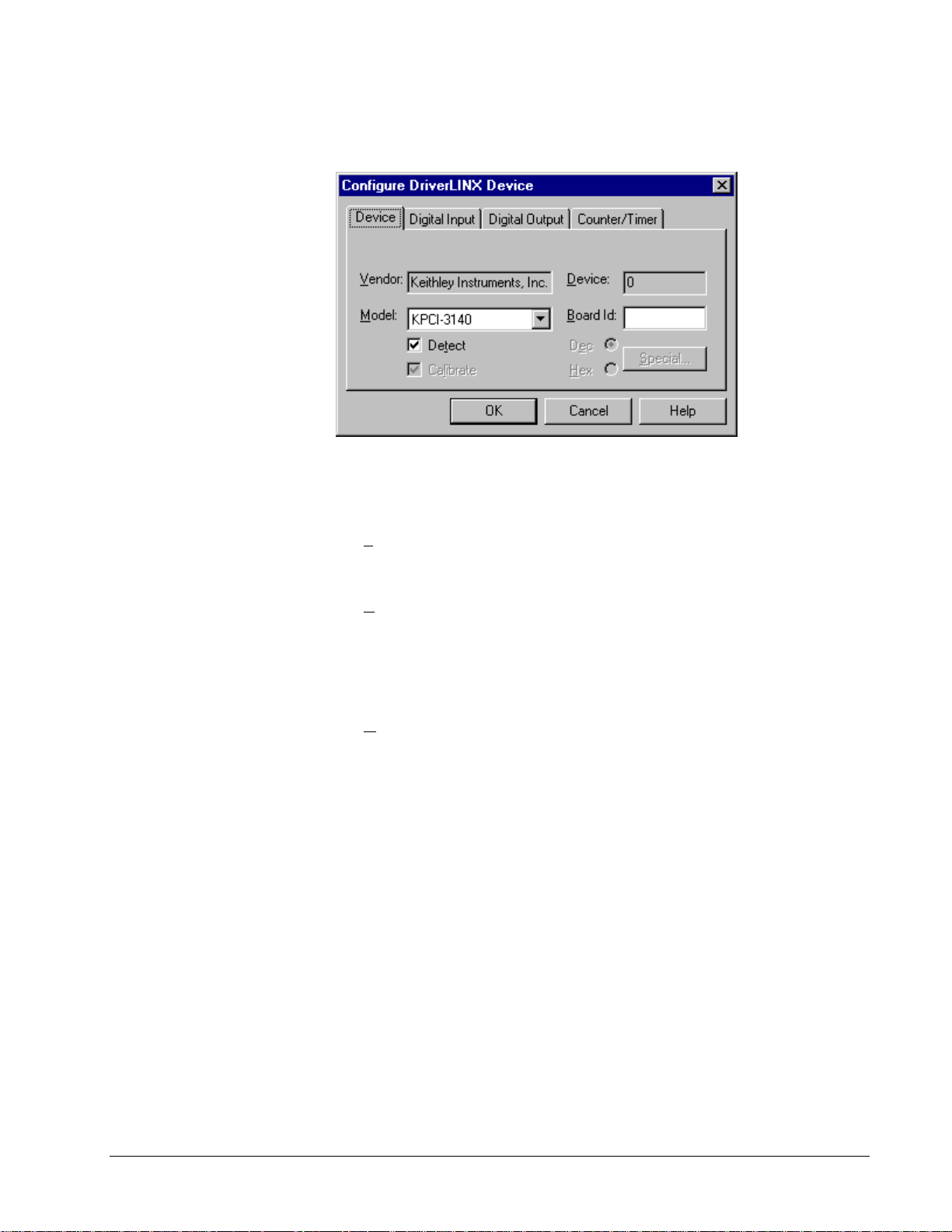
Device Subsystem Page
Use the Device subsystem page to tell DriverLINX the model name of your KPCI 3140 Series board.
Vendor
The Vendor property displays “Keithley Instruments, Inc.” It is a read-only property.
Device
Windows NT
Windows 95/98
The Device property designates the Logical Device you are configuring. It is a readonly property. To change it, first save (OK) or quit (Cancel) the current
configuration. Then select or create a new Logical Device using the DriverLINX
Configuration Panel.
Model
The Model property selects or indicates the hardware model of the board you’re
configuring.
Select the following model:
KPCI-3140
Windows 95 automatically determines the model of your board so DriverLINX
disables Model selection.
Board Id
The KPCI-3140 Series boards do not have unique serial numbers that DriverLINX
can use to match a Logical Device to a board while loading the driver. Under
Windows 95/98, DriverLINX can match a Logical Device to a board based on the
bus slot. Under Windows NT, DriverLINX matches Logical Devices in the sequence
that Windows enumerates them on the bus.
Windows NT
Using DriverLINX with Your Keithley KPCI-3140 Series Configuring the KPCI-3140 Series • 13
DriverLINX does not use the Board Id property.
Windows 95/98
DriverLINX assigns a Board Id based on bus slot.
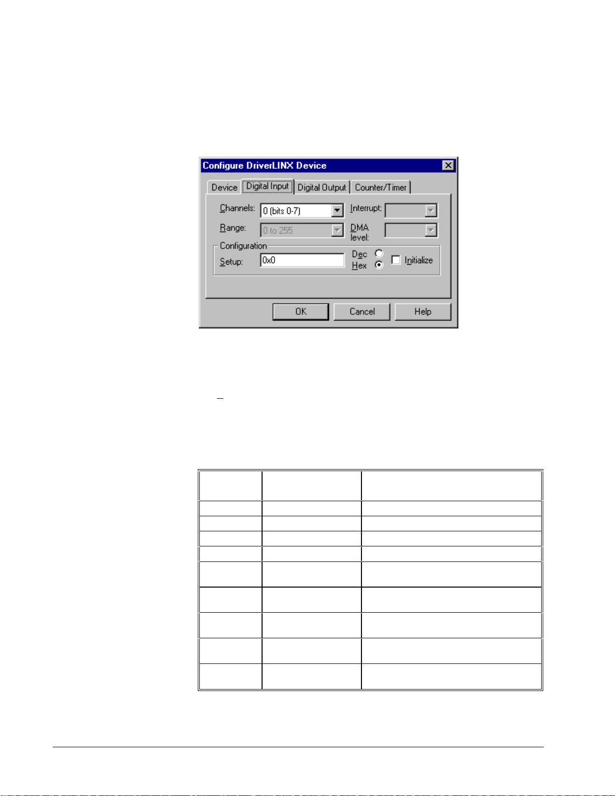
Digital Input Subsystem Page
Use the Digital Input subsystem page to set configurable digital channels as input or
output.
Channels
The Channels property allows you to select a Logical Channel for configuration or
viewing the channel’s range.
The KPCI-3140 Series supports both fixed and configurable digital channels.
DriverLINX defines the following Logical Channels for the KPCI-3140 Series
Digital Input Subsystem:
Model KPCI-3140
Logical
Channel
0 Digital Input/Output Digital I/O Bank A 0 … 7
1 Digital Input/Output Digital I/O Bank B 0 … 7
2 Digital Input/Output Digital I/O Bank C 0 … 7
3 Digital Input/Output Digital I/O Bank D 0 … 7
4
5
6
7
8 External Trigger (edge-
DriverLINX
Function
Digital Input (interrupt
register)
External Clock (patternsensitive)
External Clock (edgesensitive)
External Trigger
(pattern-sensitive)
sensitive)
KPCI-3100 Series External
Connector
Digital I/O Bank D 0 … 7
Digital I/O Bank D 0 … 7
Digital I/O Bank D 0 … 7
Digital I/O Bank D 0 … 7
Digital I/O Bank D 0 … 7
14 • Configuring the KPCI-3140 Series Using DriverLINX with Your Keithley KPCI-3140 Series

Range
The Range property specifies the supported digital input range for the selected
Logical Channel. This is a read-only property.
Interrupt
Windows automatically determines the interrupt level for the KPCI-3140 board.
DriverLINX disables this property.
DMA
The KPCI-3140 Series does not use DMA channels for direct memory transfers.
DriverLINX disables this property.
Configuration Setup
The Confi gur at i on Setup property specifies the hardware configuration of the digital
I/O ports. Logical Channels 0 through 1 are configurable as input or output. Enter 1
to initially configure the selected channel as input or 0 to configure it as output a nd
check the Initialize box.
Initialize
Checking the I n itia lize check box instructs DriverLINX to use the Configuration
Setup property to configure the selected digital I/O channel.
Using DriverLINX with Your Keithley KPCI-3140 Series Configuring the KPCI-3140 Series • 15

Digital Output Subsystem Page
Use the Digital Output subsystem page to change the default digital ou tp ut port
initialization values.
Channels
The Channels property allows you to select a Logical Channel for initialization or
viewing the channel’s range.
Model KPCI-3140
Logical
Channel
0 Digital Input/Output Digital I/O Bank A 0 … 7
1 Digital Input/Output Digital I/O Bank B 0 … 7
2 Digital Input/Output Digital I/O Bank C 0 … 7
3 Digital Input/Output Digital I/O Bank D 0 … 7
DriverLINX
Function
KPCI-3100 Series External
Connector
Range
The Range property specifies the supported digital output range for the selected
Logical Channel. This is a read-only property.
Interrupt
Windows automatically determines the interrupt level for the KPCI-3140 board.
DriverLINX disables this property.
DMA
The KPCI-3140 Series does not use DMA channels for direct memory transfers.
DriverLINX disables this property.
Initialization Value
The Initialization Value property specifies the digital output value DriverLINX will
write to the selected Logical Channel upon hardware initialization. DriverLINX only
writes this value if you enable the Initialize check box.
16 • Configuring the KPCI-3140 Series Using DriverLINX with Your Keithley KPCI-3140 Series

Initialize
Checking the I n itia lize check box instructs DriverLINX to use the Initialization
Value property for digital output port initialization.
Dec
This check box converts the Initialization Value property to decimal.
Hex
This check box converts the Initialization Value property to hexadeci mal.
Using DriverLINX with Your Keithley KPCI-3140 Series Configuring the KPCI-3140 Series • 17

Counter/Timer Subsystem Page
Use the Count er/Timer subsystem page to view the clock source frequency.
Resolution
The Resolution property specifies the clock frequency of the master oscillator. All
models have a 20 MHz clock source for pacing input/output tasks and counter/timer
functions.
Interrupt
Windows automatically determines the interrupt level for the KPCI-3140 board.
DriverLINX disables this property.
18 • Configuring the KPCI-3140 Series Using DriverLINX with Your Keithley KPCI-3140 Series

Using the KPCI-3140 Series with
DriverLINX
Introduction
See the Counter/Timer,
Digital I/O or Analog I/O
Programming Guides for an
overview of DriverLINX
programming.
This chapter shows you how to set up and use KPCI-3140 Series hardware features
with DriverLINX.
The descriptions here use the Edit Service Request dialog for language and API
independence. For the correct syntax with the language you’re using, please see the
DriverLINX Technical Reference Manuals. For DriverLINX examples in your
programming language, please see the source code examples in the subdirectories of
your DriverLINX installation directory or on the original distribution media.
KPCI-3140 Series Hardware Features
The KPCI-3140 Series offers your data-acquisition application a wide variety of
useful features. Digital I/O ports support pre- and post-triggering. Eight of the
counter/timers are user-accessible. DriverLINX accesses these features through its
hardware independent Applications Programming Interface (API).
The following table is a cross-reference between hardware features and the
DriverLINX features that access them.
Hardware Feature DriverLINX Feature
Digital Input/Output Ports
Digital Port Configuration Initial Configuration:
• Digital Input Subsystem
• Digital Output Subsystem
• Configuration Setup
Application Configuration:
• Digital Input Digital Channel
Configuration
• Digital Output Digital Channel
Configuration
Using DriverLINX with Your Keithley KPCI-3140 Series Using the KPCI-3140 Series with DriverLINX • 19

Hardware Feature DriverLINX Feature
Digital triggering Digital Input:
• Digital Start Event (Post-
Triggering)
• Digital Stop Event (Pre-
Triggering)
Digital Output:
• Digital Start Event (Post-
Triggering)
• Digital Stop Event (Pre-
Triggering)
User-accessible counter/timers
• Counter/Timer Subsystem
DriverLINX Hardware Model for KPCI-3140 Series
DriverLINX provides a portable, hardware-independent API for data-acquisition
boards while still allowing applications to access unique or proprietary hardware
features of specific products. To achieve this goal, DriverLINX maps a hardwareindependent, or abstract, data-acquisition model onto KPCI-3140 Series hardware
capabilities.
The following sections describe how DriverLINX implements KPCI-3140 Series
hardware features as Subsyste ms, Modes, Operations, Events, Logical Channels,
Buffers, and Messages.
DriverLINX Subsystems
The KPCI-3140 Series supports the following DriverLINX subsystems:
1. Device—refers to a KPCI-3140 Series board as a whole.
2. Digital Input—refers to the digital input ports as well as 1-bit digital
control signals and external clock inputs.
3. Digital Output—refers to the digital output ports.
4. Counter/Timer—refers to the onboard counter/timer channels for
pacing digital input/output or performing measuring and waveform
generation functions.
DriverLINX Modes
Applications use modes in Service Requests to advise DriverLINX on their preferred
hardware data transfer technique. The DriverLINX modes fall into two general
classes:
• Foreground or synchronous modes. The calling application does not
regain control until DriverLINX completes the Service Request.
DriverLINX supports this mode for simple, single value I/O operations
or software housekeeping functions that DriverLINX can complete
without a significant delay.
20 • Using the KPCI-3140 Series with DriverLINX Using DriverLINX with Your Keithley KPCI-3140 Series

• Background or asynchronous mo des. The calling application regains
control as soon as DriverLINX initiates the task. The calling
application must synchronize with the data-acquisition task using status
polling or DriverLINX’s messages (preferred). DriverLINX supports
this mode for buffered data transfers or for commands that require a
significant time to complete.
DriverLINX supports four modes with the KPCI-3140 Series for its commands
(Service Requests).
• Polled Mode—This is a foreground or synchronous operation.
DriverLINX supports this mode for simple, single-value I/O operations
that the data-acquisition board can complete without significant delay.
• Interrupt Mode—This is a background or asynchronous operation.
DriverLINX transfers data between the computer’s memory and the
data-acquisition board using hardware interrupts and programmed I/O
transfers.
• Other Mode—This is a foreground or synchronous operation.
DriverLINX supports this mode for initialization, configuration,
calibration, data conversion, and timebase operations.
The following table summarizes the data acquisition modes that DriverLINX
supports for each subsystem with the Keithley KPCI-3140 Series.
Subsystem Polled Interrupt Other
Digital Input
Digital Output
Counter/Timer
Device
√√√
√√√
√√√
√
KPCI-3140 Series Supported DriverLINX Modes.
Using DriverLINX with Your Keithley KPCI-3140 Series Using the KPCI-3140 Series with DriverLINX • 21

DriverLINX Operations and Events
Applications construct DriverLINX data-acquisition tasks by combining a small
number of DriverLINX operations and events in many possible ways. The following
table summarizes the operations and events that DriverLINX supports for the
Keithley KPCI-3140 Series. Later sections for each DriverLINX subsystem will
describe the operations and events in more detail.
Note: In addition to the operations shown in the table below, all subsystems allow
the MESSAGE operation in any Mode.
Subsystem Operation Events
Mode Timing Start Stop
Digital Input
Polled Start null null, cmd null, TC
Interrupt Start, Stop,
Status
Other Initialize,
Configure
Digital Output
Polled Start null null, cmd null, TC
Interrupt Start, Stop,
Status
Other Initialize,
Configure
rate, dig cmd, dig cmd, TC, dig
DIO Setup
rate, dig cmd, dig cmd, TC, dig
DIO Setup
Counter/Timer
Polled Start, S top,
Status
Interrupt Start, Stop,
Status
Other Initialize,
Configure
Device
Other Initialize,
Capabilities
Allowed Operations and Events for KPCI-3140 Series Subsystems and Modes.
null, rate null, cmd null, TC
rate cmd, dig cmd, TC, dig
rate
The following list explains the Event abbreviations in the preceding table:
• null—Null or None Event specifies when a Service Request does not
require an event
• cmd—Command Event specifies when DriverLINX starts or stops a
task on software command
• TC—Terminal Count Event specifies when DriverLINX processes all
data buffers once
• rate—Rate Event specifies how DriverLINX paces or clocks data
transfer
22 • Using the KPCI-3140 Series with DriverLINX Using DriverLINX with Your Keithley KPCI-3140 Series

• dig—Digital Event specifies a trigger, clock, or other co ntrol signa l to
pace, start, or stop a task
• DIO Setup—DIO Setup Event assigns a digital channel to either the
Digital Input or Digital Output Subsystem.
Logical Channels
DriverLINX designates the individually addressable hardware channels for each
subsystem as “Logical Channels.” Generally, the zero-based Logical Channel
numbering sequence closely follows the hardware manufacturer’s channel
numbering scheme.
In some cases, however, DriverLINX assigns Logical Channel numbers to hardware
features that users don’t commonly think of as “channels.” For instance, DriverLINX
commonly models external hardware clock input lines, external hardware trigger
input lines, and external interrupt inputs as 1-bit digital Logical Cha nnels. In other
cases, DriverLINX models subsystem-specific features, such as internal pacer
clocks, as members of a more general-purpose set of counter/timer channels.
For a list of DriverLINX assigned Logical Channel numbers, see the notes on each
supported subsystem.
Buffers
Applications usually use data buffers to exchange data between the application and
the data-acquisition hardware. When using data buffers, please note the following
points about DriverLINX’s data buffers:
• DriverLINX supports data-acquisition tasks with 1 to 255 data buffers
per task.
• DriverLINX imposes no size limits on a single buffer, although the
operating system or some hardware products may have size restrictions.
• User applications must allow DriverLINX to allocate all data buffers to
guarantee application portability to different hardware and opera ting
systems and to insure that the hardware can physically access the buffer
memory.
• User applications usually don’t have concurrent or immediate access to
the in-use data buffer while DriverLINX is executing a data-acquisition
task.
Using DriverLINX with Your Keithley KPCI-3140 Series Using the KPCI-3140 Series with DriverLINX • 23

Connecting Signals to the KPCI-3140 Series
The Keithley hardware manual descri bes the data a nd control signals for the K PCI3140 Series and the connector pinouts for these signals. This section summarizes
how DriverLINX numbers the I/O data signals and how DriverLINX uses the control
connections for external clock, trigger, and gating inputs.
Digital Input Subsystem Signals
The Digital Input Subsystem has four programmable digital input/output ports, one
of which can be used for ti ming or triggering. It also ha s an interrup t status register
that DriverLINX models a digital input channel. DriverLINX maps the se signals to
Logical Channels as shown in the following table:
Model KPCI-3140
Logical
Channel
0 Digital Input/Output Digital I/O Bank A 0 … 7
1 Digital Input/Output Digital I/O Bank B 0 … 7
2 Digital Input/Output Digital I/O Bank C 0 … 7
3 Digital Input/Output Digital I/O Bank D 0 … 7
4 Digital Input (interrupt
5
6
7
8
DriverLINX
Function
register)
External Clock (pattern-
sensitive)
External Clock (edge-
sensitive)
External Trigger
(pattern-sensitive)
External Trigger (edge-
sensitive)
KPCI-3100 Series External
Connector
Digital I/O Bank D 0 … 7
Digital I/O Bank D 0 … 7
Digital I/O Bank D 0 … 7
Digital I/O Bank D 0 … 7
Digital I/O Bank D 0 … 7
How DriverLINX maps digital input hardware channels to Logical Channels.
Notes:
• If a channel is configured for output, reading it using the Digital Input
subsystem returns the last value written.
• The External Trigger and External Clock channels are not available for
reading but are available for clocking and triggering.
• Applications can assign a configurable channel to either digital
subsystem using a Configure operation. (See “Di gital Channe l
Configuration” on page 29.)
Digital Input Pacing, Triggering and Gating Signals
Digital input tasks are either polled mode or interrupt mode. In interrupt mode, the
Digital Input subsystem can use several control signals that DriverLINX defines as
external clocks and triggers as shown in the following table:
24 • Using the KPCI-3140 Series with DriverLINX Using DriverLINX with Your Keithley KPCI-3140 Series

Connector Name DriverLINX Usage
Digital I/O Bank D 0…7 External trigger:
• Digital Start Event (Post-Triggering)
• Digital Stop Event (Pre-Triggering)
External pacer clock:
• Digital Timing Event
User Clock Inputs
How DriverLINX uses digital input control signals.
• Divider-Rate Generator: External Clocking
Using DriverLINX with Your Keithley KPCI-3140 Series Using the KPCI-3140 Series with DriverLINX • 25

Digital Output Subsystem Signals
The Digital Output Subsystem has four programmable digital input/output ports.
DriverLINX maps these signals to Logical Channels as shown in the following table:
Model KPCI-3140
Logical
Channel
0 Digital Input/Output Digital I/O Bank A 0 … 7
1 Digital Input/Output Digital I/O Bank B 0 … 7
2 Digital Input/Output Digital I/O Bank C 0 … 7
3 Digital Input/Output Digital I/O Bank D 0 … 7
How DriverLINX maps digital output hardware channels to Logical Channels.
Notes:
Digital Output Pacing, Triggering and Gating Signals
Digital output tasks are either polled mode or interrupt mode. In interrupt mode, the
Digital Output subsystem can use several control signals that DriverLINX defines as
external clocks and triggers as shown in the following table:
DriverLINX
Function
KPCI-3100 Series External
Connector
• If a channel is configured for output, reading it (using the Digital Input
subsystem) returns the last value written.
• Applications can assign a configurable channel to either digital
subsystem using a Configure operation. (See “Di gital Channe l
Configuration” on page 29.)
Connector Name DriverLINX Usage
Digital I/O Bank D 0…7 External trigger:
• Digital Start Event (Post-Triggering)
• Digital Stop Event (Pre-Triggering)
External pacer clock:
• Digital Timing Event
User Clock Inputs
How DriverLINX uses digital input control signals.
• Divider-Rate Generator: External Clocking
Counter/Timer Subsystem Signals
The Counter/Timer subsystem has a Logical Channel for each of the counter/timer
chip’s twelve counter/timers. The first eight have external clock, gate and output pins
but support only counter/timer tasks. The last four have only clock inputs but do
support pacing tasks on other subsystems.
26 • Using the KPCI-3140 Series with DriverLINX Using DriverLINX with Your Keithley KPCI-3140 Series

DriverLINX maps these signals as shown in the following table:
Model KPCI-3140
Logical
Channel
0
1 Pacing and
2 Pacing and
3
4 Pacing and
5 Pacing and
6
7 Pacing and
8 Pacing
9 Pacing
10 Pacing
11 Pacing
*
Interrupts from Digital I/O Bank D 0 … 7 can start or stop any counter/timer.
How DriverLINX maps counter/timer hardware channels to Logical Channels.
DriverLINX
Function
Pacing and
Counter/Timer tasks
Counter/Timer tasks
Counter/Timer tasks
Pacing and
Counter/Timer tasks
Counter/Timer tasks
Counter/Timer tasks
Pacing and
Counter/Timer tasks
Counter/Timer tasks
KPCI-3100 Series External
Connector
User Clock Input 0
User Clock Output 0
External Gate 0
User Clock Input 1
User Clock Output 1
External Gate 1
User Clock Input 2
User Clock Output 2
External Gate 2
User Clock Input 3
User Clock Output 3
External Gate 3
User Clock Input 4
User Clock Output 4
External Gate 4
User Clock Input 5
User Clock Output 5
External Gate 5
User Clock Input 6
User Clock Output 6
External Gate 6
User Clock Input 7
User Clock Output 7
External Gate 7
*
Using DriverLINX with Your Keithley KPCI-3140 Series Using the KPCI-3140 Series with DriverLINX • 27

Device Subsystem
The following sections describe how DriverLINX implements Device Subsystem
features for the KPCI-3140 Series.
Device Modes
The Device Subsystem supports only DriverLINX’s Other mode for all operations.
Device Operations
The KPCI-3140 Series Device Subsystem supports the following DriverLINX
operations:
If another application is using
the same data-acquisition
board, DriverLINX will
prevent Device Initialization
from interfering with another
application’s data-acquisition
tasks.
• Initialize—DriverLINX aborts all data-acquisition tasks for every
subsystem controlled by the current application. DriverLINX then
initializes each subsystem.
• Capabilities—DriverLINX provides hardware-specific and
configuration information in the form of a Logical Device Descriptor
database. (If you are using the DriverLINX ActiveX controls, access
the Logical Device Descriptor with a DriverLINXLDD control rather
than with this operation.)
28 • Using the KPCI-3140 Series with DriverLINX Using DriverLINX with Your Keithley KPCI-3140 Series

Digital Input Subsystem
The following sections describe how DriverLINX imple ments Digital Input
Subsystem features for the KPCI-3140 Series.
Digital Input Modes
The Digital Input Subsystem supports the following modes:
• Polled—For single-value or scan digital input samples.
• Interrupt—For buffered transfers using programmed I/O.
• Other—For subsystem initialization and configuration.
Digital Input Operations
The KPCI-3140 Series Digital Input Subsystem supports the following DriverLINX
operations:
• Initialize—aborts any active interrupt data-acquisition tasks and stops
• Configure—assigns a configurable digital channel to the input
• Start—initiates a data-acquisition task using the Mode, Timing, Start,
the associated clocks. However, DriverLINX prevents one application
from interfering with another application’s data-acquisition tasks.
subsystem.
and Stop Events, the Logical Channels, and the Buffers the application
specified in the Service Request.
• Status—reports the buffer position of the next sample that DriverLINX
will write into a buffer.
• Stop—terminates a digital input data-acqui sition task.
• Message—displays a pop-up dialog box for the user containing the text
for the current DriverLINX error message.
Digital Channel Configuration
The KPCI-3140 Series has four configurable digital channels. To use a digital
channel as an input, you must first assign it to the Digital Input Subsys tem using the
“Configure DriverLINX Device Dialog” (page 12) or by using a Configure
operation.
To configure a digital channel, submit a service request with following settings :
• Subsystem—Digital Input or Digital Output
• Mode—Other
• Operation—Configure
• Timing Event—DIO Setup
• DIO Setup Channel—Logical Channel number
• DIO Setup Mode—DIO BASIC
Using DriverLINX with Your Keithley KPCI-3140 Series Using the KPCI-3140 Series with DriverLINX • 29

For more information, see the following topics in the Digital I/O Programming
Guide:
• Configuring a Digital Port at Run Time
• Determining the Digital Port Configuration
Example: For a programming example, see DIOCNFIG in your DrvLINX4\Source
folder.
Digital Input Timing Events
Timing Events specify how the hardware paces or clocks the reading of Digital Input
samples. DriverLINX uses the Timing Event to program when the KPCI-3140 Series
reads the next digital input sample from the ports.
The KPCI-3140 Series supports the following Timing Events:
• None—Input requires no pacing as DriverLINX is reading only a
single value or scan.
• Rate—The KPCI-3140 Series supports fixed rate sampling using
internal and external clocks.
• Digital—The KPCI-3140 Series supports sampling using digital input
lines.
None or Null Timing Event
The Null Event specifies that the task does not need a clock to determine when to
read the next sample.
Rate Timing Event
The KPCI-3140 Series supports the following Rate Event for digital input:
• Rate Generator—Generates a fixed rate clock with equal time
intervals between tics.
• Divider—Generates a fixed rate clock by dividing an external input
frequency.
KPCI-3140 Series boards have a fixed 40 MHz master clock frequency. The sample
period range depends on the counter/timer. The 24-bit Interval Timers limit the
period to
period to
details.
1224− tics, or 419430 µs (2.39 Hz), and the 16-bit User Clocks limit the
1216− tics, or 1638 µs (611 Hz). Consult your hardware manual for
30 • Using the KPCI-3140 Series with DriverLINX Using DriverLINX with Your Keithley KPCI-3140 Series

Rate Generator: Internal Clocking
An internally clocked Rate Generator produces a fixed rate clock with equal time
intervals between tics.
Period
Use an internally clocked rate generator when you want to acquire all digital input
scans at equally spaced time intervals.
For hardware independence,
specify the clock channel
using the symbolic constant,
DEFAULTTIMER, which
always maps to the default
Logical Channel for digital
output timing.
How to set up the KPCI-3140 Series for fixed rate sampling using an internal clock.
• Specify internal clocking using a Rate Generator on any available
channel with the Internal1 Clock source.
• The Period property specifies the time interval between samples in tics.
• The KPCI-3140 Series does not support gating the Logical Channels 8-
11. Therefore, only Disabled and NoConnect settings are valid for the
Gate property for these channels.
Divider-Rate Generator: External Clocking
A divided, externally clocked Rate Generator produces a rate clock with unknown
time intervals between tics.
Period (ext clk)
Use a divider-rate generat or when you want to synchronize samples with a recurr ent,
higher frequency, external signal. In this mode you will need a specified number of
external clock tics for each sample or scan you want to acquire.
Using DriverLINX with Your Keithley KPCI-3140 Series Using the KPCI-3140 Series with DriverLINX • 31

How to set up the KPCI-3108 Series for rate sampling using a divided external clock.
Be sure that the external
clock source is TTL
compatible, 0 V minimum to
+5 V maximum!
• Specify external clocking using a Divider Generator on Channel 0-7
with an External, or External+ Clock source.
• Users should connect the external clock signal to the associated User
Clock Input line.
• Specify the divisor for the external frequency in the Period property.
• The Gate property specifies how the gate signal affects the operation of
the pacer clock. Valid settings for the TGIN gate are Enabled,
Disabled, NoConnect, High Level and Low Leve l.
Digital Timing Event
DriverLINX supports Digital Events for timing based on patterns or edges of
external clock sources.
Period (ext clk)
Use an externally clocked rate generator when you want to synchronize digital input
samples with a recurrent external signal. You need a separate external clock tic for
each sample or scan you want to acquire.
32 • Using the KPCI-3140 Series with DriverLINX Using DriverLINX with Your Keithley KPCI-3140 Series

How to set up for external rate samp l in g using a digital event.
• Specify the Channel as 5 for pattern-sensitive clocki ng or 6 for edge-
sensitive clocking. For hardware-independence, you can speci fy the
hardware pattern-sensitive, external clock channel by the symbolic
constant, DI_EXTCLK.
Unlike most hardware, the edge-sensitive setting sa mples upon any
change in any of the masked lines. For compatibility with the singleline, edge-sensitive clocking supported by other hardware, use a
pattern-sensitive, 1-bit clock with a Not equals match setting.
• Users should connect the external clock signals to the selected lines of
Digital I/O Bank D.
• Specify the Mask property as any value between 0 and 255 to indicate
that DriverLINX should only compare the selected 1-bit digital input
values against the Pattern property.
• For pattern-sensitive clocking, specify the Match property as Equals
or Not equals. For edge-sensitive clocking, specify the Ma tch
property as Not equals.
• For pattern-sensitive clocking, specify the Pattern property as any
subset of the Mask bits. The edge-sensitive channel do es not use the
Pattern property—specify 0 in this case.
• The channel Simultaneous property determines whether the driver
samples a single channel or an entire scan in each clock event. If you
check Simultaneous, the driver samples all of the channels in the scan.
Using DriverLINX with Your Keithley KPCI-3140 Series Using the KPCI-3140 Series with DriverLINX • 33

Digital Input Start Events
Start Events specify when the KPCI-3140 Series hardware starts reading digital input
data.
The KPCI-3140 Series supports the following Start Events for digital input:
• None—Use this event when the DriverLINX oper a tion does not require
a Start Event.
• Command—DriverLINX starts the task on software command, i.e., as
soon as DriverLINX finishes programming the KPCI-3140 hardware
for the task.
• Digital—The hardware starts acquiring samples when the hardware
detects the digital channel input satisfies the condition specified in the
Start Event.
None or Null Start Event
The Null Event specifies that the task does not need a Start Event to begin the task.
Command Start Event
The Command Event starts data acquisition as soon as DriverLINX has completed
programming the KPCI-3140 Series hardware with the task parameters.
Digital Start Event (Post-Triggering)
The KPCI-3140 can acquire digital input samples after the hardware detects a digital
trigger condition. Use post-triggering when you want to synchro nize the start of data
acquisition with an external signal.
How to set up the KPCI-3140 Series for post-triggered digital input.
34 • Using the KPCI-3140 Series with DriverLINX Using DriverLINX with Your Keithley KPCI-3140 Series

Digital Start Events contain mask, pattern, and match fields. The mask is logically
ANDed with the digital input data on the Logical Channel and then compared with
the pattern for a match/mismatch.
• Specify the Channel as 7 for pattern-sensitive triggering or 8 for edge-
sensitive triggering. For hardware-independence, you can specify the
hardware pattern-sensitive, external trigger channel by the symbolic
constant, DI_EXTTRG.
Unlike most hardware, the edge-sensitive setting triggers upo n any
change in any of the masked lines. For compatibility with the singleline, edge-sensitive trigger supported by other hardware, use a patternsensitive, 1-bit trigger with a Not equals match setting.
• Users should connect the external trigger signals to the selected lines of
Digital I/O Bank D.
• Specify the Mask property as any value between 0 and 255 to indicate
that DriverLINX should only compare the selected 1-bit digital input
values against the Pattern property.
• For pattern-sensitive triggering, specify the Match property as Equals
or Not equals. For edge-sensitive triggering, specify the Match
property as Not equals.
• For pattern-sensitive triggering, specify the Pattern property as any
subset of the Mask bits. The edge-sensitive channel do es not use the
Pattern property—specify 0 in this case.
• Specify the Delay property as 0; the hardware does not support delayed
triggering.
Digital Input Stop Events
Stop Events specify when the KPCI-3140 Series hardware stops reading digital input
data.
The KPCI-3140 Series supports the following Stop Events for digital input:
• None—Use this event when the DriverLINX oper a tion does not require
a Stop Event.
• Command—DriverLINX stops the task on software command, i.e.,
when the application issues a Service Request with a Stop operation.
• Terminal count—DriverLINX stops the task after the KPCI-3140
Series hardware has filled all the data buffers once.
• Digital—The hardware stops acquir ing samples when the hardware
detects the digital Logical Channel input satisfies the condition
specified in the Stop Event.
None or Null Stop Event
The Null Event specifies that the task does not need a Stop Event to end the task.
Command Stop Event
The Command Event stops data acquisition when the user application c hanges the
Operation property in the Service Request to Stop and resubmits the Service Request
to DriverLINX.
Using DriverLINX with Your Keithley KPCI-3140 Series Using the KPCI-3140 Series with DriverLINX • 35

In Stop-on- Command mod e, DriverLINX continuously cycles through all the data
buffers, filling them with digital input data from the data-acquisitio n hardware.
Terminal Count Stop Event
The Terminal Count Event stops data acquisition after DriverLINX ha s r ead the
digital input data into all the data buffers once. Use terminal count when you want to
read a fixed amount of data.
Digital Stop Event (Pre-Triggering)
The KPCI-3140 can acquire digital input samples until the hardware detects a digital
trigger condition. Use pre-triggering when you want to synchronize the end of data
acquisition with an external signal.
How to set up the KPCI-3140 Series for pre-triggered digital input.
Digital Stop Events contain mask, pattern, and match fields. The mask is logically
ANDed with the digital input data on the Logical Channel and then compared with
the pattern for a match/mismatch.
• Specify the Channel as 7 for pattern-sensitive triggering or 8 for edge-
sensitive triggering. For hardware-independence, you can specify the
hardware pattern-sensitive, external trigger channel by the symbolic
constant, DI_EXTTRG.
Unlike most hardware, the edge-sensitive setting triggers upo n any
change in any of the masked lines. For compatibility with the singleline, edge-sensitive trigger supported by other hardware, use a patternsensitive, 1-bit trigger with a Not equals match setting.
• Users should connect the external trigger signals to the selected lines of
Digital I/O Bank D.
• Specify the Mask property as any value between 0 and 255 to indicate
that DriverLINX should only compare the selected 1-bit digital input
values against the Pattern property.
36 • Using the KPCI-3140 Series with DriverLINX Using DriverLINX with Your Keithley KPCI-3140 Series

Note:
• For pattern-sensitive triggering, specify the Match property as Equals
or Not equals. For edge-sensitive triggering, specify the Match
property as Not equals.
• For pattern-sensitive triggering, specify the Pattern property as any
subset of the Mask bits. The edge-sensitive channel do es not use the
Pattern property—specify 0 in this case.
• Specify the Delay property as 0; the hardware does not support delayed
triggering.
When the hardware detects the trigger, DriverLINX sends a StopEvent
message (or event) that identifies sample following the trigger. Fo r
more information, see “Digital Input Messages” on page 43 .
Using DriverLINX with Your Keithley KPCI-3140 Series Using the KPCI-3140 Series with DriverLINX • 37

Digital Input Channels
The KPCI-3140 Series allows applications to specify the digital channels using three
techniques:
• Start Channel—Acquire data from a single channel.
• Start/Stop Channel Range—Acquire data from a consecutive range of
channels.
• Channel List—Acquire data from a list of channels.
Digital Input Logical Channels
The KPCI-3140 Series supports four configurable digital channels. DriverLINX
defines the following Logical Channels for the KPCI-3140 Series Digital Input
Subsystem:
Model KPCI-3140
Logical
Channel
0 Digital Input/Output Digital I/O Bank A 0 … 7
1 Digital Input/Output Digital I/O Bank B 0 … 7
2 Digital Input/Output Digital I/O Bank C 0 … 7
3 Digital Input/Output Digital I/O Bank D 0 … 7
4 Digital Input (interrupt
5 External Clock (pattern-
6 External Clock (edge-
7 External Trigger
8 External Trigger (edge-
DriverLINX
Function
register)
sensitive)
sensitive)
(pattern-sensitive)
sensitive)
KPCI-3100 Series External
Connector
Digital I/O Bank D 0 … 7
Digital I/O Bank D 0 … 7
Digital I/O Bank D 0 … 7
Digital I/O Bank D 0 … 7
Digital I/O Bank D 0 … 7
The KPCI-3140 boards have four 8-bit banks of programmable digital I/O lines.
Users can configure a port as input or output using the DriverLINX Configuration
Panel. Application can o verride a po rt’s configura t ion using a Configure service
request. For details, see “Digital Channel Configuration” on page 29.
Bank D lines set a flag and raise an interrupt upon any rising or failing signal ed ge
when they are used as timing or triggering signals. For maximum application
flexibility, applications can read the interrupt flag register as Logical Channel 4
(along with other channels if desired) using a polled or interrupt mode task.
To support DriverLINX’s hardware-independent API, the driver defines additional
Logical Channels (5 t hrough 8) for Bank D. Channels 5 and 6 are timing event
channels, while 7 and 8 are start and stop event channels. At each interrupt, the
driver inspects the interrupt register and compares the Port D reading with event
parameters in the service request. For the pattern-sensitive channels (5 and 7) , the
driver responds to the event if the masked reading and pattern meet the match
38 • Using the KPCI-3140 Series with DriverLINX Using DriverLINX with Your Keithley KPCI-3140 Series

condition. For the edge-sensitive channels (6 and 8), the driver responds to the event
if any of the masked lines have their interrupt flags set.
Notes:
• When using the external clock or trigger channels, Logical Channel 3 is
normally configured as an input port. If not, interrupts occur when
values are written to the port rather than in response to external signals.
• The DriverLINX symbolic channels, DI_EXTTRG and DI_EXTCLK,
map to the pattern-sensitive channels so they behave similarly to
hardware that has a single, edge-sensitive trigger or external clock
input. By matching the pattern, the driver ensures the triggers occur
only on the selected edge and clocks occur on only one edge of an
external clock pulse.
Using DriverLINX with Your Keithley KPCI-3140 Series Using the KPCI-3140 Series with DriverLINX • 39

Single Channel Digital Input
In single channel mode, the KPCI-3140 Series acquires all data from one channel.
How to set up the KPCI-3140 Series for sampling on a single channel.
Multi-channel Digital Input Range
In multi-channel range mode, the KPCI-3140 Series acquires data from a
consecutive range of digital channels.
• The Stop Channel must be greater than the Start Channel.
How to set up the KPCI-3140 Series for sampling on a consecutive range of channels.
40 • Using the KPCI-3140 Series with DriverLINX Using DriverLINX with Your Keithley KPCI-3140 Series

Multi-channel Digital Input List
In multi-channel list mode, the KPCI-3140 Series acquires data from an arbitrary list
of digital channels.
How to set up the KPCI-3140 Series to sample from an arbitrary list of channels.
Digital Input Buffers
DriverLINX supports single-value, single-scan and buffered digital input.
• For single-value input, specify the Number of buffers as 0. The buffer
for a single value is the ioValue property.
• For single-scan input, specify the Number of buffers as 1 and the
number of Samples equal to the number of channels.
• For buffered input, specify the Number of buffers from 1 to 255 and
the number of Samples as desired.
Using DriverLINX with Your Keithley KPCI-3140 Series Using the KPCI-3140 Series with DriverLINX • 41

How to set up the KPCI-3140 Series to read digital samples using data buffers.
Buffer Usage
DriverLINX fills buffers sequentially until the task stop s. During the task, only
complete buffers are available to the application. Except for tasks that stop on
terminal count, the last buffer may be only partially full. Use a Status operation to
determine the location of the last sample.
42 • Using the KPCI-3140 Series with DriverLINX Using DriverLINX with Your Keithley KPCI-3140 Series

Digital Input Messages
For digital input operations, DriverLINX can report the following messages to the
application:
DriverLINX
Explanation
Message
Service Start DriverLINX has started the acqu i sition task.
Service Done DriverLINX has completed the acquisition task.
Start Event DriverLINX has detected the h ardware start event.
Stop Event DriverLINX has detected the hardware stop even t.
Buffer Filled DriverLINX has filled a buffer.
Data Lost DriverLINX has detected a data overrun
Critical Error DriverLINX h as encountered an unexpected hard ware or
software condition.
DriverLINX Event messages for digital input.
For detailed explanations of these messages see one of the following references:
• DriverLINX Technical Reference Manual for C/C++ users
• DriverLINX/VB Technical Reference Manual for VB or Delphi users
Using DriverLINX with Your Keithley KPCI-3140 Series Using the KPCI-3140 Series with DriverLINX • 43

Digital Output Subsystem
The following sections describe how DriverLINX implements Digital Output
Subsystem features for the KPCI-3140 Series.
Digital Output Modes
The Digital Output Subsystem supports the following modes:
• Polled—For single-value or scan digital output samples.
• Interrupt—For buffered transfers using programmed I/O.
• Other—For subsystem initialization and configuration.
Digital Output Operations
The KPCI-3140 Series Digital Output Subsystem supports the following
DriverLINX operations:
• Initialize—aborts any active interrupt data-acquisition tasks and stops
the associated clocks. However, DriverLINX prevents one application
from interfering with another application’s data-acquisition tasks.
• Configure—assigns a configurable digital channel to the output
subsystem.
• Start—initiates a data-acquisition task using the Mode, Timing, Start,
and Stop Events, the Logical Channels, and the Buffers the application
specified in the Service Request.
• Status—reports the buffer position of the next sample that DriverLINX
will read from a buffer.
• Stop—terminates a digital output data-acquisition task.
• Message—displays a pop-up dialog box for the user containing the text
for the current DriverLINX error message.
Digital Output Initialization
By default, Digital Output Subsystem initialization writes zeros to the all the digital
I/O ports configured for output. You can specify a different initial output value using
the Configure DriverLINX Device dialog. See “Digital Output Subsystem Page” on
page 16.
Digital Channel Configuration
The KPCI-3140 Series has four configurable digital channels. To use a digital
channel as an output, you must first assign it to the Digital Output Subsystem using
the “Configure DriverLINX Device Dialog” (page 12) or by using a Configure
operation. See “Digital Channel Configuration” on page 29 for more information on
the configure operation.
44 • Using the KPCI-3140 Series with DriverLINX Using DriverLINX with Your Keithley KPCI-3140 Series

Digital Output Timing Events
Timing Events specify how the hardware paces or clocks writing Digital Output
samples. DriverLINX uses the Timing Event to program when the KPCI-3140 Series
writes the next digital output sample to the ports.
The KPCI-3140 Series supports the following Timing Events for digital output:
• None—Output requires no pacing as DriverLINX is writing only a
single value or scan.
• Rate—The KPCI-3140 Series supports fixed rate sampling using
internal and external clocks.
• Digital—The KPCI-3140 Series supports sampling using digital input
lines.
None or Null Timing Event
The Null Event specifies that the task does not need a clock to determine when to
write the next sample.
Rate Timing Event
The KPCI-3140 Series supports the following Rate Event for digital input:
• Rate Generator—Generates a fixed rate clock with equal time
intervals between tics.
• Divider—Generates a fixed rate clock by dividing an external input
frequency.
KPCI-3140 Series boards have a fixed 40 MHz master clock frequency. The sample
period range depends on the counter/timer. The 24-bit Interval Timers limit the
period to
period to
details.
1224− tics, or 419430 µs (2.39 Hz), and the 16-bit User Clocks limit the
1216− tics, or 1638 µs (611 Hz). Consult your hardware manual for
Using DriverLINX with Your Keithley KPCI-3140 Series Using the KPCI-3140 Series with DriverLINX • 45

Rate Generator: Internal Clocking
An internally clocked Rate Generator produces a fixed rate clock with equal time
intervals between tics.
Period
Use an internally clocked rate generator when you want to acquire all digital input
scans at equally spaced time intervals.
For hardware independence,
specify the clock channel
using the symbolic constant,
DEFAULTTIMER, which
always maps to the default
Logical Channel for digital
output timing.
How to set up the KPCI-3140 Series for fixed rate sampling using an internal clock.
• Specify internal clocking using a Rate Generator on any available
channel with the Internal1 Clock source.
• The Period property specifies the time interval between samples in tics.
• The KPCI-3140 Series does not support gating the Logical Channels 8-
11. Therefore, only Disabled and NoConnect settings are valid for the
Gate property for these channels.
Divider-Rate Generator: External Clocking
A divided, externally clocked Rate Generator produces a rate clock with unknown
time intervals between tics.
Period (ext clk)
Use a divider-rate generator when you want to synchronize sample s with a recurr ent,
higher frequency, external signal. In this mode you will need a specified number of
external clock tics for each sample or scan you want to acquire.
46 • Using the KPCI-3140 Series with DriverLINX Using DriverLINX with Your Keithley KPCI-3140 Series

How to set up the KPCI-3108 Series for rate sampling using a divided external clock.
Be sure that the external
clock source is TTL
compatible, 0 V minimum to
+5 V maximum!
• Specify external clocking using a Divider Generator on Channel 0-7
with an External, or External+ Clock source.
• Users should connect the external clock signal to the associated User
Clock Input line.
• Specify the divisor for the external frequency in the Period property.
• The Gate property specifies how the gate signal affects the operation of
the pacer clock. Valid settings for the TGIN gate are Enabled,
Disabled, NoConnect, High Level and Low Leve l.
Digital Timing Event
DriverLINX supports Digital Events for timing based on patterns or edges of
external clock sources.
Period (ext clk)
Use an externally clocked rate generator when you want to synchronize digital input
samples with a recurrent external signal. You need a separate external clock tic for
each sample or scan you want to acquire.
Using DriverLINX with Your Keithley KPCI-3140 Series Using the KPCI-3140 Series with DriverLINX • 47

How to set up for external rate samp l in g using a digital event.
• Specify the Channel as 5 for pattern-sensitive clocki ng or 6 for edge-
sensitive clocking. For hardware-independence, you can speci fy the
hardware pattern-sensitive, external clock channel by the symbolic
constant, DI_EXTCLK.
Unlike most hardware, the edge-sensitive setting sa mples upon any
change in any of the masked lines. For compatibility with the singleline, edge-sensitive clocking supported by other hardware, use a
pattern-sensitive, 1-bit clock with a Not equals match setting.
• Users should connect the external clock signals to the selected lines of
Digital I/O Bank D.
• Specify the Mask property as any value between 0 and 255 to indicate
that DriverLINX should only compare the selected 1-bit digital input
values against the Pattern property.
• For pattern-sensitive clocking, specify the Match property as Equals
or Not equals. For edge-sensitive clocking, specify the Ma tch
property as Not equals.
• For pattern-sensitive clocking, specify the Pattern property as any
subset of the Mask bits. The edge-sensitive channel do es not use the
Pattern property—specify 0 in this case.
• The channel Simultaneous property determines whether the driver
samples a single channel or an entire scan in each clock event. If you
check Simultaneous, the driver samples all of the channels in the scan.
48 • Using the KPCI-3140 Series with DriverLINX Using DriverLINX with Your Keithley KPCI-3140 Series

Using DriverLINX with Your Keithley KPCI-3140 Series Using the KPCI-3140 Series with DriverLINX • 49

Digital Output Start Events
Start Events specify when the KPCI-3140 Series hardware starts writing digital
output data.
The KPCI-3140 Series supports the following Start Events for digital output:
• None—Use this event when the DriverLINX oper a tion does not require
a Start Event.
• Command—DriverLINX starts the task on software command, i.e., as
soon as DriverLINX finishes programming the KPCI-3140 hardware
for the task.
• Digital—The hardware starts writing samples when the hardware
detects the digital channel input satisfies the condition specified in the
Start Event.
None or Null Start Event
The Null Event specifies that the task does not need a Start Event to begin the task.
Command Start Event
The Command Event starts data acquisition as soon as DriverLINX has completed
programming the KPCI-3140 hardware with the task parameters.
Digital Start Event (Post-Triggering)
The KPCI-3140 can write samples after the hardware detects a digital trigger
condition. Use post-triggering when you want to synchronize the start of data
acquisition with an external signal.
How to set up the KPCI-3140 Series for post-triggered digital output.
50 • Using the KPCI-3140 Series with DriverLINX Using DriverLINX with Your Keithley KPCI-3140 Series

Digital Start Events contain mask, pattern, and match fields. The mask is logically
ANDed with the digital input data on the Logical Channel and then compared with
the pattern for a match/mismatch.
• Specify the Channel as 7 for pattern-sensitive triggering or 8 for edge-
sensitive triggering. For hardware-independence, you can specify the
hardware pattern-sensitive, external trigger channel by the symbolic
constant, DI_EXTTRG.
Unlike most hardware, the edge-sensitive setting triggers upo n any
change in any of the masked lines. For compatibility with the singleline, edge-sensitive trigger supported by other hardware, use a patternsensitive, 1-bit trigger with a Not equals match setting.
• Users should connect the external trigger signals to the selected lines of
Digital I/O Bank D.
• Specify the Mask property as any value between 0 and 255 to indicate
that DriverLINX should only compare the selected 1-bit digital input
values against the Pattern property.
• For pattern-sensitive triggering, specify the Match property as Equals
or Not equals. For edge-sensitive triggering, specify the Match
property as Not equals.
• For pattern-sensitive triggering, specify the Pattern property as any
subset of the Mask bits. The edge-sensitive channel do es not use the
Pattern property—specify 0 in this case.
• Specify the Delay property as 0; the hardware does not support delayed
triggering.
Digital Output Stop Events
Stop Events specify when the KPCI-3140 Series hardware stops writing digital
output data.
The KPCI-3140 Series supports the following Stop Events for digital output:
• None—Use this event when the DriverLINX oper a tion does not require
a Stop Event.
• Command—DriverLINX stops the task on software command, i.e.,
when the application issues a Service Request with a Stop operation.
• Terminal count—DriverLINX stops the task after the KPCI-3140
Series hardware has written all the data buffers once.
• Digital—The hardware stops writi ng samples when the hardware
detects the digital Logical Channel input satisfies the condition
specified in the Stop Event.
None or Null Stop Event
The Null Event specifies that the task does not need a Stop Event to end the task.
Terminal Count Stop Event
The Terminal Count Event stops data acquisition a fter DriverLI NX has written the
digital output data from all the data buffers once. Use terminal count when you want
to write a fixed amount of data.
Using DriverLINX with Your Keithley KPCI-3140 Series Using the KPCI-3140 Series with DriverLINX • 51

Digital Stop Event (Pre-Triggering)
The KPCI-3140 can write digital output samples until the hardware detects a digital
trigger condition. Use pre-triggering when you want to synchronize the end of data
acquisition with an external signal.
How to set up the KPCI-3140 Series for pre-triggered digital output.
Digital Stop Events contain mask, pattern, and match fields. The mask is logically
ANDed with the digital input data on the Logical Channel and then compared with
the pattern for a match/mismatch.
• Specify the Channel as 7 for pattern-sensitive triggering or 8 for edge-
sensitive triggering. For hardware-independence, you can specify the
hardware pattern-sensitive, external trigger channel by the symbolic
constant, DI_EXTTRG.
Unlike most hardware, the edge-sensitive setting triggers upo n any
change in any of the masked lines. For compatibility with the singleline, edge-sensitive trigger supported by other hardware, use a patternsensitive, 1-bit trigger with a Not equals match setting.
• Users should connect the external trigger signals to the selected lines of
Digital I/O Bank D.
• Specify the Mask property as any value between 0 and 255 to indicate
that DriverLINX should only compare the selected 1-bit digital input
values against the Pattern property.
• For pattern-sensitive triggering, specify the Match property as Equals
or Not equals. For edge-sensitive triggering, specify the Match
property as Not equals.
• For pattern-sensitive triggering, specify the Pattern property as any
subset of the Mask bits. The edge-sensitive channel do es not use the
Pattern property—specify 0 in this case.
52 • Using the KPCI-3140 Series with DriverLINX Using DriverLINX with Your Keithley KPCI-3140 Series

Note:
• Specify the Delay property as 0; the hardware does not support delayed
triggering.
When the hardware detects the trigger, DriverLINX sends a StopEvent
message (or event) that identifies sample following the trigger. Fo r
more information, see “Digital Output Messages” on page 58.
Using DriverLINX with Your Keithley KPCI-3140 Series Using the KPCI-3140 Series with DriverLINX • 53

Digital Output Channels
The KPCI-3140 Series allows applications to specify the digital channels using three
techniques:
• Start Channel—Write data to a single channel.
• Start/Stop Channel Range—Write da ta to a consecutive range of
channels.
• Channel List—Write data to a list of channels.
Digital Output Logical Channels
The Digital Output subsystem has four configurable digital input/output channels.
DriverLINX maps these signals to Logical Channels as shown in the following table:
Model KPCI-3140
Logical
Channel
0 Digital Input/Output Digital I/O Bank A 0 … 7
1 Digital Input/Output Digital I/O Bank B 0 … 7
2 Digital Input/Output Digital I/O Bank C 0 … 7
3 Digital Input/Output Digital I/O Bank D 0 … 7
How DriverLINX maps digital output hardware channels to Logical Channels.
DriverLINX
Function
KPCI-3100 Series External
Connector
Notes:
• If a channel is configured for output, reading it using the Digital Input
subsystem returns the last value written.
• Applications can assign a configurable channel to either subsystem
using a Configure operation. (See “Digital Channel Configuration” on
page 29.)
Single Channel Digital Output
In single channel mode, the KPCI-3140 Series writes all data from one channel.
54 • Using the KPCI-3140 Series with DriverLINX Using DriverLINX with Your Keithley KPCI-3140 Series

How to set up the KPCI-3140 Series for writing to a single channel.
Multi-channel Digital Output Range
In multi-channel range mode, the KPCI-3140 Series acquires all data from a
consecutive range of digital channels.
• The Stop Channel must be greater than the Start Channel.
How to set up the KPCI-3140 Series for writing to a consecutive range of channels.
Using DriverLINX with Your Keithley KPCI-3140 Series Using the KPCI-3140 Series with DriverLINX • 55

Multi-channel Digital Output List
In multi-channel list mode, the KPCI-3140 Series acquires all data from an arbitrary
list of digital channels.
How to set up the KPCI-3140 Series to write to an arbitrary list of channels.
56 • Using the KPCI-3140 Series with DriverLINX Using DriverLINX with Your Keithley KPCI-3140 Series

Digital Output Buffers
DriverLINX supports single-value, single-scan and buffered digital output.
• For single-value output, specify the Number of buffers as 0. The
buffer for a single value is the ioValue property.
• For single-scan output, specify the Number of buffers as 1 and the
number of Samples equal to the number of channels.
• For single-scan output, specify the Number of buffers as 1 and the
number of Samples equal to the number of channels.
How to set up the KPCI-3140 Series to store samples in buffers.
Buffer Usage
DriverLINX writes buffers sequentially until the task stops. D urin g the task, only
empty buffers are available to the application. Except for tasks that stop on terminal
count, the last buffer may be only partially used. Use a Status operation to determine
the location of the last sample.
Using DriverLINX with Your Keithley KPCI-3140 Series Using the KPCI-3140 Series with DriverLINX • 57

Digital Output Messages
For digital output operations, DriverLINX can repor t the following messages to the
application:
DriverLINX
Explanation
Message
Service Start DriverLINX has started the acqu i sition task.
Service Done DriverLINX has completed the acquisition task.
Start Event DriverLINX has detected the h ardware start event.
Stop Event DriverLINX has detected the hardware stop even t.
Buffer Filled DriverLINX has emptied a buffer.
Data Lost DriverLINX has detected a data overrun
Critical Error DriverLINX has encountered an unexpected hardware or
software condition.
DriverLINX Event messages for digital output.
For detailed explanations of these messages see one of the following references:
• DriverLINX Technical Reference Manual for C/C++ users
• DriverLINX/VB Technical Reference Manual for VB or Delphi users
58 • Using the KPCI-3140 Series with DriverLINX Using DriverLINX with Your Keithley KPCI-3140 Series

Counter/Timer Subsystem
The KPCI-3140 Series provides counter/timers for digital input/output pacing as well
as independent counter/timer tasks. The KPCI-3140 Series uses the same proprietary
counter/timer chip as the KPCI-3100 Counter/Timer board.
The KPCI-3140 Series also has external interrupt inputs via Digital I/O Bank D. The
driver can start or stop Counter/Timer tasks in response to these inputs. See “Digital
Input Subsystem Signals” on page 24 for connection details.
The KPCI-3140 has eight 16-bit general-purpose counter/timers that support a wide
variety of counting and generation functions. DriverLINX designates these counters
as Logical Channels 0 through 7. Each counter/timer has a clock input, a gate input
and a counter output.
The KPCI-3140 also has four 24-bit dedicated counter/timers. These can be used to
generate TimerTic messages or to pace buffered digital input or output. DriverLINX
designates these counters as Logical Channels 8 through 11. These channels have no
external connections.
Model KPCI-3140
Logical
Channel
0 Pacing and
1 Pacing and
2
3 Pacing and
4 Pacing and
5
6 Pacing and
7 Pacing and
8 Pacing
9 Pacing
10 Pacing
11 Pacing
*
Interrupts from Digital I/O Bank D 0 … 7 can start or stop any counter/timer.
DriverLINX
Function
Counter/Timer tasks
Counter/Timer tasks
Pacing and
Counter/Timer tasks
Counter/Timer tasks
Counter/Timer tasks
Pacing and
Counter/Timer tasks
Counter/Timer tasks
Counter/Timer tasks
KPCI-3100 Series External
Connector
User Clock Input 0
User Clock Output 0
External Gate 0
User Clock Input 1
User Clock Output 1
External Gate 1
User Clock Input 2
User Clock Output 2
External Gate 2
User Clock Input 3
User Clock Output 3
External Gate 3
User Clock Input 4
User Clock Output 4
External Gate 4
User Clock Input 5
User Clock Output 5
External Gate 5
User Clock Input 6
User Clock Output 6
External Gate 6
User Clock Input 7
User Clock Output 7
External Gate 7
*
Using DriverLINX with Your Keithley KPCI-3140 Series Using the KPCI-3140 Series with DriverLINX • 59

An application specifies operating parameters for a counter/timer using a Rate Event
for the timing event in a service request. A Rate Event has clock source, mode and
gate properties. DriverLINX defines many useful generic counter/timer functions
that can be performed with most counter/timer chips. Alternatively, you can use
DriverLINX to program the board in specific modes of the proprietary, KPCI-3140
compatible, counter/timer chip. See the DriverLINX Counter/Timer User’s Guide for
detailed information on programming the KPCI-3140 counter/timer chip.
The following sections discuss usage of Rate Event properties for both input/output
task and counter/timer tasks.
Counter/Timer Channel Usage
The following table shows which Logical Chan nels are available for timing tasks on
each subsystem.
Counter/Timer Logical Channel Usage
Counter/Timer Channel
Subsystem 01234567891011
Digital Input
Digital Output
Counter/Timer
Avail = Available; Def = Default.
Avail Avail Avail Avail Avail Avail Avail Avail
Avail Avail Avail Avail Avail Avail Avail Avail Avail
Avail Avail Avail Avail Avail Avail Avail Avail Avail Avail Avail
Def
For portability across drivers, applications can specif y the default timing channel
using the symbolic constant DEFAULTTIMER, rather than a specific channel
number.
Avail Avail Avail
Def
Def
Avail Avail
A Counter/Timer Subsystem Task can read the current value of any of the 16-bit
counter/timers (Logical Channels 0-7) by referencing the channel in the service
request’s channel list or range.
Clock Sources and Modes
DriverLINX defines one internal and several external clock sources, and several
modes for Rate Events on the KPCI-3140 Series. Some apply only to pacing while
other are only for certain counter/timer tasks. The following tables lists the clock
sources and the modes to which they apply for use with each subsystem:
Digital Input / Digital Output
Name Source Modes
Internal 1 Internal 40 MHz RateGen
External
External-
External A/D Clock Input RateGen
60 • Using the KPCI-3140 Series with DriverLINX Using DriverLINX with Your Keithley KPCI-3140 Series

Counter/Timer
Name Source Modes*
Internal 1 Internal 40 MHz RateGen
TCn-1 Output of previous counter/timer** Divider
External User Counter Input 0 VDCGen
External+ User Counter Input 1 SqWave
User Counter Input 2 Freq
User Counter Input 3 Freq32
User Counter Input 4 Count
User Counter Input 5 Count32
User Counter Input 6 Count64
User Counter Input 7 PulseWd
PulseGen
OneShot
*Some modes use multiple counter/timers so they do not app ly to all channel s. See
the Counter/Timer Programming Guide for details.
**Applies only to channels 1 through 3 and 5 through 7.
For portability across hardware with different drivers, applicatio ns ca n use the
Sec2Tics function to determine the tic period of Internal 1.
Using DriverLINX with Your Keithley KPCI-3140 Series Using the KPCI-3140 Series with DriverLINX • 61

Gate Settings
The Gate setting specifies how the gate signal affects the operation of the internal or
external clock. The following settings are valid, depending on the subsystem:
Counter/Timer Channel
Gate Setting 01234
Enabled selects the gate’s
default enabled mode. On the
KPCI-3140 Series this is either
High Level or Rising Edge,
depending on the rate mode.
Disabled allows the clock to
run independently of the gate
signal.
No Connect normally allows
the clock to run independently
of the gate signal.
High Level enables the clo ck
only while the gate signal is
high.
Low Level enables the clock
only while the gate signal is
low.
High Edge enables the clock
after the first rising edge in the
gate signal.
Low Edge enables the clock
after the first falling edge in the
gate signal.
√√√√√√√√
√√√√√√√√√√√√
√√√√√√√√√√√√
√√√√√√√√
√√√√√√√√
√√√√√√√√
√√√√√√√√
567891011
Note: No Connect specifies that if the application is running with a board that
cannot disable its gate, then the user should leave the gate unconnected so that it
does not interfere with the data-acquisition task. This is mode is accepted by all
DriverLINX drivers.
Counter/Timer Tasks
Counter/timer tasks, as distinguished from input/output task pacing, perform various
counting, measuring, and wave and pulse generation functions. Counter /timer
hardware varies widely in complexity and utility. To simplify most counter/timer
tasks while allowing applications to access to features of particular chips,
DriverLINX allows applications to specify either function-oriented task or hardwareoriented tasks.
62 • Using the KPCI-3140 Series with DriverLINX Using DriverLINX with Your Keithley KPCI-3140 Series

DriverLINX’s function-oriented tasks that the KPCI-3140 Series can perform are
• Event Counting
Repetitive 16, 32 or 64-bit event counting with optio nal level gating
Non-repetitive 16, 32 or 64-bit event counting without gating
• Frequency Measurement
Non-repetitive, 16 or 32-bit frequency measurement with optional level
gating (these functions require external interconnections)
• Pulse Width Measurement
Non-repetitive measurement of high or low pulses with optional level
gating
• Pulse Generation
Non-repetitive pulse generation
• Frequency Generation with optional level gating
Variable duty cycle wa veform generation
Square wave genera tion
Periodic pulse trains
For more information on these functions, see in “Using Task-Oriented Functions”
the Counter/Timer Programming Guide.
DriverLINX’s TimerTic task simply starts a single counter/timer usi ng an internal or
external clock source. It sends the application a TimerTic message after a specified
number of clock pulses. For more information see in “Using a Counter/Timer to
Generate Clock Messages” the Counter/Timer Programming Guide.
CHAN_SE_DIG=2^13
This constant is defined in
drvlinx.h.
DriverLINX’s hardware-oriented tasks start one or more counter/timers as a group.
Applications can program the KPC1-3140 Series-compatible counter/timer chip in
specific hardware modes. The counter/timer chip’s modes are
• 0—Non-retriggerable One-shot
• 1—Retriggerable One-shot
• 2—Continuous Increment
Applications can configure one or more counter/timers and interconnect them with
the KPCI-3140 circuitry. For more information see in “Configuring a Counter/Timer
Channel” the Counter/Timer Programming Guide.
DriverLINX then starts the group of counter/timers at the same time Application can
then periodically poll for the current count or use interrupt mode to buffer counter
readings. For more information see in “Status Polling a Counter/Timer” the
Counter/Timer Programming Guide.
Reading Digital Input Channels with the Counter/Timer
Subsystem
The KPCI-3140 Series can sample digital input channels along with counter/timer
channels. To use this feature, simply add the digital input logical channel numbers to
the channel-gain list of a counter/timer service request. For each entry, set the gain
equal to the special value, CHAN_SE_DIG. Instead of returning a counter/timer
channel’s count in the data buffer, the driver returns the eight-bits data value from
the digital input channel in the low byte of the buffer location. The high byte of the
buffer location is set to zero.
Using DriverLINX with Your Keithley KPCI-3140 Series Using the KPCI-3140 Series with DriverLINX • 63

Counter/Timer Messages
For counter/timer operations, DriverLINX can report the following messages to the
application:
DriverLINX
Explanation
Message
Service Start DriverLINX has started the counter/timer task.
Start Event DriverLINX has detected the h ardware start event.
Stop Event DriverLINX has detected the hardware stop even t.
Buffer Filled DriverLINX has filled a buffer.
Data Lost DriverLINX has detected a data overrun
Service Done DriverLINX has completed the counter/timer task.
Critical Error DriverLINX h as encountered an unexpected hard ware or
software condition.
DriverLINX Event messages for counter/timer tasks.
For detailed explanations of these messages see one of the following references:
• DriverLINX Technical Reference Manual for C/C++ users
• DriverLINX/VB Technical Reference Manual for VB or Delphi users
64 • Using the KPCI-3140 Series with DriverLINX Using DriverLINX with Your Keithley KPCI-3140 Series

Uninstalling DriverLINX
How do I uninstall DriverLINX?
DriverLINX consists of three separate component installations:
• DriverLINX for Keithley KPCI-3140 Series
• DriverLINX Programming Interfaces
• DriverLINX Documentation
You can uninstall the last two installations at any time without interfering with
compiled applications that require DriverLINX drivers. To uninstall the latter
components, run the “Add/Remove Programs” tool in the Windows Control Panel.
To uninstall DriverLINX drivers for the Keithley KPCI-3140 Series, you must
• Disable the DriverLINX driver.
• Shut down your computer to remove the hardware.
• Reboot your computer to unload the driver.
• Run the DriverLINX uninstall program.
How to Disable a DriverLINX Driver in Windows NT
1. From the Windows Start menu, select “Settings”, then “Control Panel”.
Left click on the DriverLINX Configuration icon in the Contro l Panel.
2. Select the KPCI-3140 devices you want to disable.
3. Right click on each device and select “Disabled” on the popup menu.
4. Repeat steps 2-3 for each KPCI-3140 card that you are uninstalling.
5. Close the DriverLINX Configuration Panel.
6. When finished, shut down your computer and physically remove any
installed KPCI-3140 hardware.
7. Reboot Windows.
8. To finish uninstalling, see “How to Remove DriverLINX for Keithley
KPCI-3140 Series” on page 67.
Using DriverLINX with Your Keithley KPCI-3140 Series Uninstalling DriverLINX • 65

How to Disable a DriverLINX Driver in Windows 95/98
1. From the Windows Start menu, select “Settings”, then “Control Panel”.
Left click on the System icon in the Control Panel. Select the “Device
Manager” tab in the System Properties dialog.
2. Left click the “+” icon next to “DriverLINX drivers” to display the
installed Keithley KPCI-3140 devices.
3. Select the KPCI-3140 device you want to disable.
4. Click the “Remove” button.
5. In the “Confirm Device Removal” dialog, select “OK”.
6. Repeat steps 3-5 for each KPCI-3140 card or driver that you
uninstalling.
7. When finished, click “Close”, shut down your computer, and physically
remove any installed KPCI-3140 hardware.
8. Reboot Windows.
9. To finish uninstalling, see “How to Remove DriverLINX for Keithley
KPCI-3140 Series” on page 67.
66 • Uninstalling DriverLINX Using DriverLINX with Your Keithley KPCI-3140 Series

How to Remove DriverLINX for Keithley KPCI-3140 Series
1. From the Windows Start menu, select “Settings”, then “Control Panel”.
Left click on the Add/Remove Programs icon in the Control P anel.
2. Select “DriverLINX for Keithley KPCI-3140 Series” in the
Add/Remove Programs Properties dialog.
3. Click the “Add/Remove…” button.
4. Answer “Yes” to “Are you sure you want to remove ‘DriverLINX for
Keithley KPCI-3140 Series’ and all of its components?” in the Confirm
File Deletion dialog.
5. The DriverLINX uninstall program will proceed.
The uninstall program will not remove the folder, “\DrvLINX4\System”. This fold er
contains copies of any \Windows\System or \Windows\System32 files that the
original DriverLINX installation updated.
Using DriverLINX with Your Keithley KPCI-3140 Series Uninstalling DriverLINX • 67


Troubleshooting
Solving Problems
Correct operation of your KPCI-3140 hardware requires successful completion of
three steps.
1. Windows recognizes KPCI-3140 hardware and installs drivers.
2. You configure the KPCI-3140 drivers using the DriverLINX
Configuration Panel.
3. Windows loads the KPCI-3140 drivers into memory.
If you are having a problem installing or configuring your KPCI-3140 product,
review the following notes. If these notes do not solve your prob l em, or your
problem is not described, then contact technical support and fully describe your
problem.
Solving Problems Recognizing and Installing
Drivers
Windows must recognize the KPCI-3140 hardware and then install KPCI-3140
drivers for the hardware.
• For Windows to automatically recognize the KPCI-3140 hardware, you
must install a KPCI-3140 product into your machine and restart the
computer.
• For Windows to install KPCI-3140 drivers, you must install the KPCI-
3140 driver software on the DriverLINX CD.
If you installed the KPCI-3140 hardware before you installed the DriverLINX
software, Windows 95/98 may install the KPCI-3140 hardware without drivers. To
fix this, you must instruct Windows to reinstall the P lu g-and-Play driver. Follow the
notes below for instructions.
Fixing Problems Installing Hardware Before Software on
Windows 95/98
If you installed the KPCI-3140 hardware before installing the DriverLINX software,
Windows 95/98 may install the hardware incorrectly.
1. Start Windows Device Manage r.
Using DriverLINX with Your Keithley KPCI-3140 Series Troubleshooting • 69

2. Search for “DriverLINX drivers”. If you do not see it, go to step 4.
3. Click on the “+” icon next to “DriverLINX drivers” and search for
“PCI Card”. If you find “PCI Card”, go to step 6, otherwise go to the
next step.
4. Search for “Other devices”.
5. Click on the “+” icon next to “Other devices” and search for “PCI
Card”.
6. Select “PCI Card”.
7. Click “Remove” in the Device Manager.
8. Highlight “Computer” in the Device Manager and click “Refresh”.
9. Windows should re -i nsta l l your har d war e und er “Dr ive r LI NX dr iver s” .
10. Answer “Yes” to “Do you want to restart your computer now?”
11. After rebo oting your computer, you must configure DriverLINX. See
“Configuring the KPCI-3140 Series” on page 11.
Solving Problems Configuring the Drivers
Windows automatically assigns hardware resources for the KPCI-3140 Series, but
you must still configure the KPCI-3140 drivers before using them. The DriverLINX
configuration only requires that you assign each KPCI-3140 product a unique
Logical Device number. And, on Windows NT, you must manually select the
hardware model of your KPCI-3140 Series board. See “Configuring the KPCI-3140
Series” on page 11 for more information.
Solving Problems Loading Drivers
Before the KPCI-3140 drivers can load, you must
1. Install the DriverLINX software.
2. Install the KPCI-3140 hardware into your computer.
3. Configure DriverLINX.
4. Reboot your computer.
If you have not completed the above steps, please do so before proceeding.
On both Windows NT and Windows 95/98, the operating system will automatically
assign hardware resources to the KPCI-3140 cards. Automatic resource assignment
can fail sometimes on
• Older PCI computers.
• Computers with ISA cards installed.
• Computers with no free hardware resources.
• Computers running Windows NT 4.0 with a BIOS setting designating
the operating system as Plug-and-Play Aware.
Sorting through all possibilities can be a challenge due to the sheer number of
combinations of PCI hardware designs, PC plug-in boards, and versions of
Windows. The following sections will help you gather informat ion about why a
driver may have failed to load. This information is essential for you or technical
support to solve your problem.
70 • Troubleshooting Using DriverLINX with Your Keithley KPCI-3140 Series

Did the DriverLINX Driver Load?
1. Run “DriverLINX Configuration” fr om Windows Control Panel.
2. Select the “DriverLINX” tab.
3. Click the “+” icon next to DriverLINX to expand the list of drivers, if
necessary.
4. Select “Keithley KPCI-3140 Series”. Click “+”, if necessary, to expand
the list.
5. Select the line with the number of the Logical Device you configured.
If the number does not exist on Windows NT or, on Windows 95/98,
you see only a hardware description, you did not configure the dr iver.
See “Configuring the KPCI-3140 Series” on page 11.
6. Click the “Properties…” button and then select the “General” tab.
7. Do you see “Status: Device Loaded”? If not, did you reboot the
computer after configuring? If not, reboot now and repeat the above
steps.
8. If you rebooted the computer after configuring and Windows did not
load your device, see “Checking for Device Errors” on page 71.
Checking for Device Errors
When a DriverLINX kernel driver cannot load, it usually writes an explanation into
the system event log. You can view this log under Windows 95/98 or Windows NT
using the DriverLINX Event Viewer.
Windows 95/98 maintains additional driver infor mation in the Device Manager. Also
see “Getting More Driver Information on Windows 95/98” on page 72.
1. Run “DriverLINX Event Viewer” from the DriverLINX folder.
2. Click on the “+” icon next to “DriverLINX” in the left panel.
3. Select the abbreviation for your driver.
4. Does the first line in the right panel show a current error?
5. Double click on the error line to see more detail and an explanatory
message.
6. If you cannot resolve the problem yourself, please provide this error
information when contacting technical support.
Using DriverLINX with Your Keithley KPCI-3140 Series Troubleshooting • 71

Getting More Driver Information on Windows 95/98
Windows 95/98 reports additio nal infor mation about device status using the Device
Manager. To access this utility,
1. Right click on “My Computer” and then select “Properties”.
2. Select “Device Manager” and “View devices by type
3. Does “DriverLINX drivers” appear in the list? If not, see “Solving
Problems Recognizing and Installing Drivers” on page 69.
4. Click the “+” next to “DriverLINX drivers”.
5. Does your KPCI-3140 product appear in the list? If not, see “Solving
Problems Recognizing and Installing Drivers” on page 69.
6. Does the icon next to your KPCI-3140 product display an exclamation
point (!)? If no, Windows has loaded your KPCI-3140 driver.
7. Select the line with the “!” and then click “Properties”.
8. The General tab will show the reason why the driver did not load.
9. The Resources tab will show if Windows detected an unreso lvable
hardware conflict.
Getting More Driver Information on Windows NT
On Windows NT, the only reasons that a driver does not load are
• You did not install the driver software.
• You did not correctly configure the driver.
• You changed the driver startup parameters.
• Your BIOS setting designates the opera ting system as Plug-and-Play
aware. (Applies only to Window NT 4.0).
An incorrectly configured driver will report the reasons that it failed to lo ad into the
Windows Event Log. See “Checking for Device Errors” on page 71 for more
information.
Under Windows NT 4.0, a Logical Device may not load because the operating
system does not always configure Plug-and-Play PCI devices properly. This may
result in unexpected or no Event Log entries. To work around this, set your
computer’s BIOS to configure Plug-and-Play devices before it starts the operating
system. On various computers the BIOS setting is called “Plug-and-Play Aware OS –
Disabled” or “Plug & Play OS – No”.
On Windows NT, DriverLINX drivers load automatically during system boot. An
administrator can change the startup command for any NT driver to either “manual”
or “disabled”.
1. Run “DriverLINX Configuration” fr om Windows Control Panel.
2. Select the “DriverLINX” tab.
3. Click the “+” icon next to DriverLINX to expand the list of drivers, if
necessary.
4. Select “Keithley KPCI-3140 Series”. Click “+”, if necessary, to expand
the list.
5. Select the line with the number of the Logical Device that did not load.
72 • Troubleshooting Using DriverLINX with Your Keithley KPCI-3140 Series

6. Right click the mouse to see a popup menu.
7. Select “Automatic” to instruct Windows to load the driver the next time
you reboot.
Generating a DriverLINX Configuration Report
Your DriverLINX installation includes a troubleshooting tool that generates a report
of your DriverLINX configuration. If you call Technical Support, after reading
“Solving Problems” on page 69, they may ask you to generate and e-mail this report
to help you solve installation and configuration pro blems.
What is in the Report?
The troubleshooting tool analyzes your computer to obtain information about
DriverLINX and operating system software that would assist Technical Support in
troubleshooting a problem you are having. It includes information on DriverLINX
files, environment variables, registry entries, hardware and the operating system.
How do I Generate the Report?
You can easily generate the report by clicking the shortcut in this topic in the help
file. Once the troubleshooting tool generates the report, you will have the
opportunity to review it and make deletions, if desired, before e-mailing it to
Technical Support. If you do not have direct access to e-mail, you can save the report
to a disk file and send a copy later. A Technical Support engineer will guide you
through these steps when you are asked to send a report.
Using DriverLINX with Your Keithley KPCI-3140 Series • 73
 Loading...