

Page 1

Keithley KPCI-3130 Series
Page 2

Information in this document is subject to change without notice. The software
described is this document is furnished under a license agreement. The software may
be used or copied only in accordance with the terms of the agreement.
SCIENTIFIC SOFTWARE TOOLS, INC. SHALL NOT BE LIABLE FOR ANY
SPECIAL, INCIDENTAL, OR CONSEQUENTIAL DAMAGES RELATED TO
THE USE OF THIS PRODUCT. THIS PRODUCT IS NOT DESIGNED WITH
COMPONENTS OF A LEVEL OF RELIABILITY SUITABLE FOR USE IN LIFE
SUPPORT OR CRITICAL APPLICATIONS.
This document may not, in whole or in part, be copied, photocopied, reproduced,
translated or reduced to any electronic medium or machine readable form without
prior written consent from Scientific Software Tools, Inc.
Keithley KPCI-3130 Series: Using DriverLINX with Your Hardware
Copyright 2000 by Scientific Software Tools, Inc.
All rights reserved.
Second Printing.
SST 32-1000-1
DriverLINX, SSTNET, and LabOBJX are registered trademarks and
DriverLINX/VB is a trademark of Scientific Software Tools, Inc.
MetraByte is a trademark of Keithley Instruments, Inc.
Microsoft and Windows are registered trademarks and Visual C++ and Visual Basic
are trademarks of Microsoft Corporation.
Borland is a registered trademark and Borland C++ and Delphi are trademarks of
Borland International, Inc.
All other brand and product names are trademarks or registered trademarks of their
respective companies.
Page 3

Contents
Preface 5
Software License and Software Disclaimer of Warranty............................................................5
About DriverLINX.....................................................................................................................7
About This User’s Guide...........................................................................................................7
Conventions Used in This Manual.............................................................................................9
Configuring the KPCI-3130 Series 11
Introduction..............................................................................................................................11
Configure DriverLINX Device Dialog.....................................................................................12
Using the KPCI-3130 Series with DriverLINX 25
Introduction..............................................................................................................................25
KPCI-3130 Series Hardware Features .....................................................................................25
DriverLINX Hardware Model for KPCI-3130 Series..............................................................26
Connecting Signals to the KPCI-3130 Series...........................................................................31
Device Subsystem....................................................................................................................36
Analog Output Subsystem........................................................................................................37
Device Subsystem Page.............................................................................................13
Analog Output Subsystem Page.................................................................................16
Digital Input Subsystem Page....................................................................................18
Digital Output Subsystem Page .................................................................................21
Counter/Timer Subsystem Page.................................................................................23
DriverLINX Subsystems............................................................................................26
DriverLINX Modes ...................................................................................................26
DriverLINX Operations and Events..........................................................................28
Logical Channels.......................................................................................................30
Buffers.......................................................................................................................30
Analog Output Subsystem Signals.............................................................................31
Digital Input Subsystem Signals................................................................................32
Digital Output Subsystem Signals..............................................................................33
Counter/Timer Subsystem Signals.............................................................................35
Device Modes............................................................................................................36
Device Operations .....................................................................................................36
Analog Output Modes................................................................................................37
Analog Output Operations.........................................................................................37
Analog Output Pacing, Triggering and Gating Options.............................................37
Analog Output Timing Events...................................................................................37
Analog Output Start Events .......................................................................................38
Analog Output Stop Events........................................................................................38
Analog Output Channels............................................................................................39
Analog Output Channel Gains...................................................................................41
Analog Output Buffers...............................................................................................42
Keithley KPCI-3130 Series Preface • 3
Page 4

Analog Output Data Coding.......................................................................................42
Analog Output Messages ...........................................................................................44
Checking for DAC Overload .....................................................................................44
Digital Input Subsystem...........................................................................................................45
Digital Input Modes...................................................................................................45
Digital Input Operations.............................................................................................45
Digital Input Pacing, Triggering and Gating Options................................................46
Digital Input Timing Events.......................................................................................46
Digital Input Start Events...........................................................................................48
Digital Input Stop Events...........................................................................................50
Digital Input Channels...............................................................................................52
Digital Input Buffers..................................................................................................56
Digital Input Messages...............................................................................................57
Digital Output Subsystem.........................................................................................................58
Digital Output Modes ................................................................................................58
Digital Output Operations..........................................................................................58
Digital Output Pacing, Triggering and Gating Options..............................................59
Digital Output Timing Events....................................................................................59
Digital Output Start Events........................................................................................60
Digital Output Stop Events........................................................................................60
Digital Output Channels.............................................................................................60
Digital Output Buffers...............................................................................................64
Digital Output Messages............................................................................................64
Counter/Timer Subsystem........................................................................................................66
Uninstalling DriverLINX 67
How do I uninstall DriverLINX? .............................................................................................67
Troubleshooting 71
Solving Problems.....................................................................................................................71
Solving Problems Recognizing and Installing Drivers...............................................71
Solving Problems Configuring the Drivers................................................................72
Solving Problems Loading Drivers............................................................................72
Generating a DriverLINX Configuration Report......................................................................75
What is in the Report?................................................................................................75
How do I Generate the Report?..................................................................................75
Glossary of Terms 77
4 • Keithley KPCI-3130 Series
Page 5

Preface
Software License and Software Disclaimer of Warranty
This is a legal document which is an agreement between you, the Licensee, and S cientific Software Tools, Inc. By opening this
sealed diskette pack age, Licensee agrees to become bound by t he terms of this Agreement , which include the Software License and
Software Disclaimer of Warranty.
This Agreement constitutes the c omplete Agreement between Licensee and Scientific S oftware Tools, Inc. If Licensee does not
agree to the terms of this Agreement, do not open the diskette pack age. Promptly return t he unopened diskette pac kage and the other
items (including writt en materials, binders or ot her containers, and hardware, if any ) that are part of this product to Sc ientific Software
Tools, Inc. for a full refund. No ref unds will be given for products that have opened disk packages or missing components.
Licensing Agreement
Copyright. The software and documentation is owned by Scientific Software Tools, Inc . and is protected by both United States
copyright laws and internati onal treaty provisions. Scientif ic Software Tools, Inc. authorizes the original purchaser only (Licensee) to
either (a) make one copy of the s oftware solely f or backup or archival purpos es, or (b) transfer t he software to a single hard disk only.
The written materials acc om panying the software may not be duplicated or copied for any reason.
Trade Secret. Licensee understands and agrees that t he software is the proprietary and conf idential property of Scienti fic Soft ware
Tools, Inc. and a valuable trade secret. Licensee agrees t o use the soft ware only for the int ended use under this Lic ense, and shall not
disclose the soft ware or i t s contents to any third part y.
Copy Restrictions. The Licensee may not modify or translate the program or relat ed documentation without the prior written
consent of Scientific Software Tools, Inc. All modifications, adaptat ions, and merged porti ons of the sof tware consti tute the s oftware
licensed to the Licensee, and the terms and condit ions of this agreem ent apply to sam e. Licensee may not distribute c opies, inc luding
electronic transfer of copies, of the m odified, adapt ed or merged sof tware or accom panying writt en material s to others . Licens ee agrees
not to reverse engineer, decompil e or di sassemble any part of the s of tware.
Unauthorized copying of the s oftware, incl uding software that has been modified, merged, or included wit h other software, or of the
written materials is expressly forbidden. Licensee may not rent, trans fer or lease the software to any t hird parties. Licensee agrees to
take all reasonable steps to protect Scientific Software Tools’ software from theft, disclosure or use contrary to the terms of the Licens e.
License. Scientific Software Tools, Inc. grants the Licensee only a non-exclus ive right t o use the serializ ed copy of t he software on
a single terminal connected t o a single computer. The Licensee may not net work the software or use it on more than one com puter or
computer terminal at the s ame time.
Term. This License is eff ective until terminated. This License will terminate automatically without not ice from Scientific Software
Tools, Inc. if Lic ensee f ails to c ompl y wit h any t erm or c onditi on of thi s Lic ense. The Lic ens ee agrees upon s uch t erminat ion to ret urn or
destroy the written materials and all copies of the sof tware. The Licensee may t erminate the agreement by returning or des troying the
program and documentation and all copies thereof.
Keithley KPCI-3130 Series Preface • 5
Page 6

Limited Warranty
Scientific Software Tools, Inc. warrants that the s oftware will perform subst antially in accordance wit h the written materials and t hat
the program disk, instruc tional manuals and ref erence materials are free f rom defects in materials and workmanship under normal use
for 90 days from the date of receipt. All express or im pl i ed warranties of the software and related materials are limited to 90 days.
Except as specifical ly set forth herein, the sof tware and accom panying writ ten material s (incl uding inst ructions for use) are prov ided
“as is” without warranty of any kind. Further, Sci entific Software Tools , Inc. does not warrant, guarantee, or make any represe ntations
regarding the use, or the results of the use, of the soft ware or writt en mat erials in t erms of correc tnes s , ac curac y, reliabi lit y, current ness ,
or otherwise. The entire risk as to the results and performance of the soft ware is assumed by Licens ee and not by Scientifi c Software
Tools, Inc. or its distributors, agents or employees.
EXCEPT AS SET FORTH HEREIN, THE RE ARE NO OTHER WARRANT IE S, EI THER EXPRESS OR IMPLIED, INCLUDING BUT
NOT LIMITED TO IMPLIED WARRANTIES OF MERCHANTABILITY AND FITNESS FOR A PARTICULAR PURPOSE, WITH
RESPECT TO THE SOFTWARE, THE ACCOMPANYING WRITTEN MATERIALS, AND ANY ACCOMP ANYING HARDWARE.
Remedy. Scientific Soft ware Tools’ ent ire liability and t he Licens ee’s ex clus ive remedy s hall be, at Sc ientific S oftware Tools’ opt ion,
either (a) return of the price paid or (b) repair or replacement of the software or accompanying materials . In the event of a defect in
material or workmanship, t he item may be returned within the warranty period to S cientific Software Tools f or a replacement without
charge, provided the licensee prev iously sent in the limited warranty registration board to Sc ientific S oftware Tools, Inc ., or can furnis h
proof of the purchase of the program. This remedy is void if failure has resulted from accident, abuse, or misapplication. Any
replacement will be warranted for the remainder of the original warranty period.
NEITHER SCIENTIFIC SOFTWARE TOOLS, INC. NOR ANYONE ELSE WHO HAS BEEN INVOLVED IN THE CREATION,
PRODUCTION, SALE OR DELIV ERY OF THIS PRODUCT SHALL BE LIABLE FOR ANY DIRECT, INDIRECT, CONSEQUENTI AL,
OR INCIDENTAL DAMAGES (INCLUDING DAMAGES FOR LOSS OF BUSINESS PROFITS, BUSINESS INTERRUPTION, LOSS OF
BUSINESS INFORMATION AND THE LIKE) ARISING OUT OF THE USE OF OR THE INABILITY TO USE SUCH PRODUCT EVEN
IF SCIENTIFIC SOFTWARE TOOLS HAS BEEN ADVISED OF THE POSSIBILITY OF SUCH DAMAGES. BECAUSE SOME
JURISDICTIONS DO NOT ALLOW THE EXCLUSION OR LIMITATION OF LIABILITY FOR CONSEQUENTIAL OR INCIDENTAL
DAMAGES, OR LIMITATIONS ON DURATION OF AN IMPLI ED WARRANTY, THE ABOVE LIMITATIONS MAY NOT APPLY TO
LICENSEE.
This agreement is governed by the laws of the Commonwealth of Pennsylvania.
6 • Preface Keithley KPCI-3130 Series
Page 7

About DriverLINX
Welcome to DriverLINX for Microsoft Windows, the high-performance realtime data-acquisition device drivers for Windows application development.
DriverLINX is a language- and hardware-indepe ndent applic ation programming
interface designed to support hardware manufacturers’ high-speed analog, digital,
and counter/timer data-acquisition boards in Windows. DriverLINX is a multi-user
and multitasking data-acquisition resource manager providing more than 100 services
for foreground and background data acquisition tasks.
Included with your DriverLINX package are the following items:
• The DriverLINX API DLLs and drivers supporting your data-
acquisition hardware
• Analog I/O Panel, a DriverLINX program that verifies the installation
and configuration of DriverLINX for your analog output board and
demonstrates several virtual bench-t op instruments
• Source code for the sample programs
• The DriverLINX Application Programming Interface files for your
compiler
• DriverLINX On-line Help System
• DriverLINX Analog I/O Programming Guide
• DriverLINX Technical Reference Manual
• Supplemental Documentation on DriverLINX and your data-acquisition
hardware
About This User’s Guide
The purpose of this manual is to help you quickly learn how to configure and use t he
hardware features of Keithley’s KPCI-3130 Series boards with DriverLINX.
• For more information on the DriverLINX API, please see the
DriverLINX Technical Reference Manual.
• For additional help programming your board, please examine the source
code examples on the Distribution Disks.
This manual contains the following chapters:
Configuring the KPCI-3130 Series
Shows how to configure the KPCI-3130 Series using the Configure DriverLINX
Device dialog box.
Using the KPCI-3130 Series with DriverLINX
Shows how to set up DriverLINX with the Edit Service Request dialog box to use
KPCI-3130 Series hardware features.
Uninstalling DriverLINX
Describes how to remove DriverLINX hardware drivers and other files.
Troubleshooting
Keithley KPCI-3130 Series Preface • 7
Page 8

Gives troubleshooting tips for installing, configur ing, and loading D riverLINX
drivers.
8 • Preface Keithley KPCI-3130 Series
Page 9

Conventions Used in This Manual
The following notational conventions are used in this manual:
• A round bullet (•) identifies itemized lists.
• Numbered lists indicate a step-by-step procedure.
• DriverLINX Application Programming Interface and Windows macro
and function names are set in bold when mentioned in the text.
• DriverLINX indicates the exported function name of the device driver
DLL while DriverLINX indicates the product as a whole.
• DriverLINX Application Programming Interface identifiers, menu
items, and Dialog Box names are italicized when mentioned in the text.
• Italics are used for emphasis.
• Source code and data structure examples are displayed in Courier
typeface and bounded by a box with a single line.
Code
• A box with a double line bound tables of information.
Tables
Concept
• Important concepts and notes are printed in the left margin.
Keithley KPCI-3130 Series Preface • 9
Page 10

Page 11

Configuring the KPCI-3130 Series
Introduction
The installation program provides general instructions for installing and configuring
DriverLINX. This manual explains the steps and special features that apply to
Keithley’s KPCI-3130 Series boards.
Installing and configuring DriverLINX for a Keithley KPCI-3130 Series board
requires three steps:
1. Install DriverLINX. Follow the instructions given by the installation
program. The Read Me First instructions explain the components and
drivers you can install.
2. Configure DriverLINX. This creates a Logical Device, which stores
configuration information for your board. See “Configure Dri verLINX
Device Dialog” on page 12 for configuration options specific to a
Keithley KPCI-3130 Series model.
Windows NT
3. Install your KPCI-3130 hardware. Follow the instructions in your
hardware manual.
After configuring DriverLINX, instal l ing your board and restarting Windows, reopen
the DriverLINX Configuration Panel to make sure that DriverLINX loaded the
Logical Device for your board. If the Logical Device is not loaded, the Event Log
may have a message from the driver that explains why. You can check the Event Log
using the DriverLINX Event Viewer on the Windows Start Menu.
Under Windows NT 4.0, a Logical Device may not load because the operating
system does not always configure Plug-and-Play PCI devices properly. To work
around this, set your computer’s BIOS to configure Plug-and-Play devi ces before it
starts the operating system. On various computers the BIOS setting is called “Plugand-Play Aware OS – Disabled” or “Plug & Play OS – No”.
Keithley KPCI-3130 Series Configuring the KPCI-3130 Series • 11
Page 12

Configure DriverLINX Device Dialog
DriverLINX uses a standardized configuration protocol for all data-acquisition
hardware. Configur ation assigns an identi fying device number to a specific KPCI3130 Series board in your computer and allows you to set the emulated analog output
resolution and data format.
The installation program automatically starts the DriverLINX Configuration Panel.
To start it now, use the shortcut on the Windows Start Menu.
When you click the Configure… button on the DriverLINX Configuration Panel,
DriverLINX displays the Configure DriverLINX Device dialog. The dialog has a
page for each subsystem on the Keithley KPCI-3130 Series. The following sections
describe your choices in configuring DriverLINX to work with your board.
12 • Configuring the KPCI-3130 Series Keithley KPCI-3130 Series
Page 13

Device Subsystem Page
Use the Device subsystem page to tell DriverLINX the model name of your KPCI3130 Series board, and, optionally, the emulated analog output resolution and data
format and to enable digital I/O testing.
Vendor
The Vendor property displays “Keithley Instruments, Inc.” It is a read-only property.
Device
Windows NT
Windows 2000
Windows 95/98
The Device property designates the Logical Device you are configuring. It is a readonly property. To change it, first save (OK) or quit (Cancel) the current
configuration. Then select or create a new Logical Device using the DriverLINX
Configuration Panel.
Model
The Model property selects or indicates the hardware model of the board you’re
configuring.
Select one of the following models:
KPCI-3130
KPCI-3132
Windows 95/98 automatically determines the model of your board so DriverLINX
disables Model selection.
Board Id
The Board Id property associates this Logical Device with a specific board.
DriverLINX automatically enters the KPCI-3130’s serial number in this field.
DriverLINX use s the board’s ser ial number to uniquely recognize boards if you have
installed multiple boards of the same model into your computer.
Keithley KPCI-3130 Series Configuring the KPCI-3130 Series • 13
Page 14
Windows NT
Windows 2000
Under Windows NT or Windows 2000, Board Id is initially blank. DriverLINX will
use the Model setting to match this Logical Device to the first available board and
then enter that board’s serial number.
Windows 95/98
Windows 95/98 automatically determines which board to associate with this Logical
Device. DriverLINX enters the serial number of the board when it starts the
configuration.
Detect
The Detect property enables and disables DriverLINX’s hardware detection and
testing algorithms. For maximum system reliability, always leave this check-box
marked.
Calibrate
The Calibrate property enables and disables hardware auto-calibration. This option is
grayed-out for the KPCI-3130 Series because it does not support automatic
calibration.
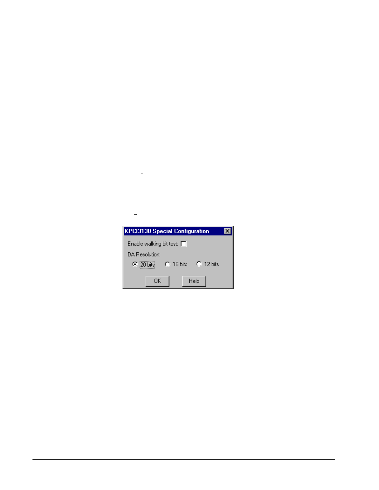
Special…
The Special… button displays the following dialog box of KPCI-3130 Series-specific
configuration options:
Enable walking bit test (Model KPCI-3130 only)
DriverLINX can perform a Walking-Bit Test when it next loads this Logical Device.
The Walking-Bit Test checks your KPCI-3130 Series board for internal digital
input/output line damage.
To perform the Walking-Bit Test:
1. Enable the test using the check box.
2. Remove the cable from your board
3. Restart your computer.
½ If the driver finds a damaged line, it makes an entry in the Event Log
and does not load the Logical Device.
½ If the test passes, the driver loads the Logical Device and clears the
check box so the test does not run again.
Important: You must remove the cable from your board for a successful test.
14 • Configuring the KPCI-3130 Series Keithley KPCI-3130 Series
Page 15

DA Resolution
DA resolution determines the data coding format and data width of digital-to-analog
samples. For the KPCI-3130 Series, the normal resolution for analog-output data
coding is 20 bits. DriverLINX provides three options for analog-output resolutions
for compatibility with application written for other hardware.
Resolution Format Width Usage
20 Bits Right-justified
two’s complement
16 Bits Two’s complement 2 Bytes Compatible with
12 Bits Right-justified
two’s complement
*You would need one of these settings only for applications that do not use
DriverLINX’s hardware-independent data conversion functions.
4 Bytes Normal setting
applications that
assume samples
are two bytes
wide*
2 Bytes Compatible with
applications that
assume a rightjustified, 12-bit,
two’s complement
format*
Keithley KPCI-3130 Series Configuring the KPCI-3130 Series • 15
Page 16

Analog Output Subsystem Page
Use the Analog Output subsystem page to set or view the initial output voltages.
Channels
Lists the analog output channels on the board and selects a channel for the Volts and
Initialize properties.
Model KPCI-3130
Physical
Connector Name Logical
Channel
1 OUT1, GND 0
2 OUT2, GND 1
3 OUT3, GND 2
4 OUT4, GND 3
5 OUT5, GND 4
6 OUT6, GND 5
7 OUT7, GND 6
8 OUT8, GND 7
Model KPCI-3132
Physical
Connector Name Logical
Channel
1 OUT1, GND 0
2 OUT2, GND 1
Range
Channel
Channel
The KPCI-3130 Series has a single, fixed analog output range or +/-10V.
DriverLINX grays out this property in the configuration dialog.
16 • Configuring the KPCI-3130 Series Keithley KPCI-3130 Series
Page 17

Volts
The Initialization Value property specifies the analog output value DriverLINX will
write to the selected Logical Channel upon hardware initialization. DriverLINX only
writes this value if you enable the Initialize check box.
Interrupt
Windows automatically determines the interrupt level for the KPIC-3130 Series
board. DriverLINX disables this property.
DMA
The KPCI-3130 Series does not use DMA channels for direct memory transfers.
DriverLINX disables this property.
Initialize
Checking the Initialize check box instructs DriverLINX to use the Volts property for
to initialize the selected analog output channel.
Keithley KPCI-3130 Series Configuring the KPCI-3130 Series • 17
Page 18

Digital Input Subsystem Page
Use the Digital Input subsystem page to set configurable digital channels as input or
output.
Channels
The Channels propert y allows you to select a Logi cal Channel for configuration or
viewing the channel’s range.
The KPCI-3130 Series supports both fixed and configurable digital channels.
DriverLINX defines the following Logical Channels for the KPCI-3130 Series
Digital Input Subsystem:
Model KPCI-3130
Logical
Channel
0 Digital Input/Output Bit 0, DGND … Bit 7, DGND
1 Digital Input/Output Bit 8, DGND … Bit 15, DGND
2 Digital Input/Output Bit 16, DGND … Bit 23, DGND
3 Digital Input/Output Bit 24, DGND … Bit 31, DGND
4 Digital Input/Output
5 Reserved
6 External Clock
7 External Trigger
Model KPCI-3132
DriverLINX
Function
(read DAC overload
flags)
(sample on DAC
overload)
(trigger on DAC
overload)
KPCI-3130 Series External
Connector
S1H,S1L … S8H, S8L
S1H,S1L … S8H, S8L
S1H,S1L … S8H, S8L
Logical DriverLINX KPCI-3130 Series External
18 • Configuring the KPCI-3130 Series Keithley KPCI-3130 Series
Page 19

Channel Function Connector
0 Reserved
1 Reserved
2 Reserved
3 Reserved
4 Digital Input/Output
(read DAC overload
flags)
5 Reserved
6 External Clock
(sample on DAC
overload)
7 External Trigger
(trigger on DAC
overload)
S1H,S1L … S2H, S2L
S1H,S1L … S2H, S2L
S1H,S1L … S2H, S2L
Range
The Range property specifies the supported digital input range for the selected
Logical Channel. This is a read-only property.
Interrupt
Windows automatically determines the interrupt level for the KPIC-3130 board.
DriverLINX disables this property.
DMA
The KPCI-3130 Series does not use DMA channels for direct memory transfers.
DriverLINX disables this property.
Configuration Setup
The Configuration Setup property specifies the hardware configuration of the digital
I/O ports. Logical Channels 0 through 3 are configurable as input or output. A setup
value of 1 initially configures the selected channel as input; 0 initially configures it as
output.
To specify an initial configuration:
1. Select the Channel to configure
2. Select Dec (decimal) or Hex (hexadecimal)
3. Enter a Setup value
4. Check the Initialize box
5. Repeat for each channel
After completing the device configuration, click OK and restart Windows to reload
the device with the new configuration.
Note: Channels configured as output can have initial output values other than the
hardware default. See “Initialization Value” on page 22.
Keithley KPCI-3130 Series Configuring the KPCI-3130 Series • 19
Page 20

Initialize
Checking the Initialize check box instructs DriverLINX to use the Configuration
Setup property to configure the selected digital I/O channel.
20 • Configuring the KPCI-3130 Series Keithley KPCI-3130 Series
Page 21

Digital Output Subsystem Page
Use the Digital Output subsystem page to change the default digital output port
initialization values.
Channels
The Channels property allows you to select a Logical Channel for initialization or
viewing the channel’s range.
Models KPCI-3130
Logical
Channel
0 Digital Input/Output Bit 0, DGND … Bit 7, DGND
1 Digital Input/Output Bit 8, DGND … Bit 15, DGND
2 Digital Input/Output Bit 16, DGND … Bit 23, DGND
3 Digital Input/Output Bit 24, DGND … Bit 31, DGND
4 Digital Input/Output
Models KPCI-3132
Logical
Channel
0 Reserved
1 Reserved
2 Reserved
3 Reserved
4 Digital Input/Output
DriverLINX
Function
(reset DAC overload
flags)
DriverLINX
Function
(reset DAC overload
flags)
KPCI-3130 Series External
Connector
S1H,S1L … S8H, S8L
KPCI-3130 Series External
Connector
S1H,S1L … S2H, S2L
Keithley KPCI-3130 Series Configuring the KPCI-3130 Series • 21
Page 22

Range
The Range property specifies the supported digital output range for the selected
Logical Channel. This is a read-only property.
Interrupt
Windows automatically determines the interrupt level for the KPIC-3130 board.
DriverLINX disables this property.
DMA
The KPCI-3130 Series does not use DMA channels for direct memory transfers.
DriverLINX disables this property.
Initialization Value
The Initialization Value property specifies the digital output value DriverLINX will
write to the selected Logical Channel upon hardware initialization. DriverLINX only
writes this value if you enable the Initialize check box.
To specify an initial output value:
1. Select the Channel to initialize
2. Select Dec (decimal) or Hex (hexadecimal)
3. Enter an Initialization value
4. Check the Initialize box
5. Repeat for each channel
Initialize
Checking the Initialize check box instructs DriverLINX to use the Initialization
Value property for digital output port initialization.
Dec
This check box converts the Initialization Value property to decimal.
Hex
This check box converts the Initialization Value property to hexadecimal.
22 • Configuring the KPCI-3130 Series Keithley KPCI-3130 Series
Page 23

Counter/Timer Subsystem Page
Use the Counter/Timer subsystem page to set the default clock source frequency.
Resolution
The KPCI-3130 Series does not have a clock. DriverLINX provides a counter/timer
subsystem so that changes in DAC overload conditions can pace sampling the DAC
overload status registers Therefore, DriverLINX disables the Resolution property.
Interrupt
Windows automatically determines the interrupt level for the KPIC-3130 Series
board. DriverLINX disables this property.
Keithley KPCI-3130 Series Configuring the KPCI-3130 Series • 23
Page 24

Page 25

Using the KPCI-3130 Series with
DriverLINX
Introduction
See the Analog I /O
Programming Guide for an
overview of DriverLINX
programming.
This chapter shows you how to set up and use KPCI-3130 Series hardware features
with DriverLINX.
The descriptions here use the Edit Service Request dialog for language and API
independence. For the corr ect syntax with the language you’re using, p lease see the
DriverLINX Technical Reference Manuals. For DriverLINX examples in your
programming language, p lease see the sourc e code examples in the subdirectories of
your DriverLINX installation directory or on the original distribution media.
KPCI-3130 Series Hardware Features
The KPCI-3130 Series offers your data-acquisition application stable, remotely
sensed analog outputs and 32-bits of digital input/output. DriverLINX accesses these
features thro ugh its hardware independent Applic ations Programming Interface
(API).
The following table is a cross-reference between hardware features and the
DriverLINX features that access them.
Hardware Feature DriverLINX Feature
Differential remote sensing of DAC
voltage
Calibration of analog output channels DriverLINX provides a stand-alone
Polled read of DAC status register.
Polled reset of DAC status register .
Interrupt mode sampling of DAC status
register.
KPCI-3130 Calibration Utility.
Page 26

Hardware Feature DriverLINX Feature
32 bits of digital I/O Four 8-bit Logical Channels,
individually configurable in either the
digital input or digital output
subsystems.
DriverLINX Hardware Model for KPCI-3130 Series
DriverLINX provides a portable, hardware-independent API for data-acquisition
boards while still allowing applications to access unique or proprietary hardware
features of specific products. To achieve this goal, DriverLINX maps a hardwareindependent, or abstract, data-acquisition model onto KPCI-3130 Series hardware
capabilities.
The following sections describe how DriverLINX implements KPCI-3130 Series
hardware features as Subsystems, Modes, Operations, Events, Logical Channels,
Buffers, and Messages.
DriverLINX Subsystems
The KPCI-3130 Series supports the following DriverLINX subsystems:
• Device—refers to a KPCI-3130 Series board as a whole.
• Analog Output—refers to the analog output channels.
• Digital Input—refers to the digital input/output ports as well the status
of the DAC sensing lines.
• Digital Output—refers to the digital input/output ports as well a virtual
output port to reset the status of the DAC sensing lines.
• Counter/Timer—refers to a virtual counter/timer channel for pacing
digital input tasks that read the overload register.
DriverLINX Modes
Applications use modes in Service Requests to advise DriverLINX on their preferred
hardware data transfer technique. The DriverLINX modes fall into two general
classes:
• Foreground or synchronous modes. The calling application doesn’t
regain control until DriverLINX completes the Service Request.
DriverLINX supports this mode for simple, single value I/O operations
or software housekeeping functions that DriverLINX can complete
without a significant delay.
• Background or asynchronous modes. The calling application regains
control as soon as DriverLINX initiates the task. The calling application
must synchronize with the data-acquisition task using status polling or
DriverLINX’s messages (preferred). DriverLINX supports this mode
for buffered data transfers or for commands that require a significant
time to complete.
26 • Using the KPCI-3130 Series with DriverLINX Keithley KPCI-3130 Series
Page 27

DriverLINX supports four modes with the KPCI-3130 Series for its commands
(Service Requests).
• Polled Mode—T his is a foreground or synchronous operation.
DriverLINX supports this mode for simple, single-value or single-scan
I/O operations that the data-acquisition board can complete without
significant delay.
• Interrupt Mode—Thi s is a background or asynchronous operation.
DriverLINX transfers data between the computer’s memory and the
data-acquisition board using hardware interrupts and programmed I/O
transfers.
• Other Mode—This is a foreground or synchronous opera tion.
DriverLINX supports this mode for initialization, configuration,
calibration, data conversion, and timebase operations.
Page 28

The following table summarizes the data acquisition modes that DriverLINX
supports for each subsystem with the Keithley KPCI-3130 Series.
Subsystem Polled Interrupt DMA Other
Analog Ou tput ¥¥
Digital Input ¥¥ ¥
Digital Output ¥¥
Counter/Timer ¥
Device ¥
KPCI-3130 Series Supported DriverLINX Modes.
DriverLINX Operations and Events
Applications construct DriverLINX data-acquisition tasks by combining a small
number of DriverLINX operations and events in many possible ways. The following
table summarizes the operations and events that DriverLINX supports for the
Keithley KPCI-3130 Series. Later sections for each DriverLINX subsystem will
describe the operations and events in more detail.
28 • Using the KPCI-3130 Series with DriverLINX Keithley KPCI-3130 Series
Page 29

Note: In addition to the operations shown in the table below, all subsystems allow
the MESSAGE operation in any Mode.
Subsystem Operation Events
Mode Timing Start Stop
Analog Output
Polled Start null null, cmd null, TC
Other Initialize
Digital Input
Polled Start null null, cmd null, TC
Interrupt Start, Stop,
Status
Other Initialize,
Configure*
Digital Output
Polled Start null null, cmd null, TC
Other Initialize,
Configure*
rate, dig cmd, dig cmd, TC, dig
DIO Setup*
DIO Setup*
Counter/Timer
Other
Device
Other Initialize,
Capabilities
Allowed Operations and Events for KPCI-3130 Series Subsystems and Modes.
*Model KPCI-3130 only.
Page 30

The following list explains the Event abbreviations in the preceding table:
• null—Null or None Event specifies when a Service Request doesn’t
require an event
• cmd—Command Event specifies when DriverLINX starts or stops a
task on software command
• TC—Terminal Count Event specifies when DriverLINX processes all
data buffers once
• rate—Rate Event specifies how DriverLINX paces or clocks data
transfer
• dig—Digital Event specifies a trigger, clock, or other control signal to
pace, start, or stop a task
• DIO Setup—DIO Setup Event assigns a digital channel to either the
Digital Input or Digital Output Subsystem.
Logical Channels
DriverLINX designates the individually addressable hardware channels for each
subsystem as “Logical Channels.” Generally, the zero-based Logical Channel
numbering sequence closely follows the hardware manufacturer’s cha nnel numbering
scheme.
In some cases, however, DriverLINX assigns Logical Channel numbers to hardware
features that users don’t commonly think of as “channels.” For instance, DriverLINX
commonly models external hardware clock input lines, external hardware trigger
input lines, and external interrupt inputs as 1-bit digital Logical Channels. In other
cases, DriverLINX models subsystem-specific features, such as internal pacer clocks,
as members of a more general-purpose set of counter/timer channels.
For a list of DriverLINX assigned Logical Channel numbers, see the notes on each
supported subsystem.
Buffers
Applications usually use data buffers to exchange data between the application and
the data-acquisition hardware. When using data buffers, please note the following
points about DriverLINX’s data buffers:
• DriverLINX supports data-acquisition tasks with 0 to 255 data buffers
per task.
• DriverLINX i mposes no size limits o n a single buffer, alt hough the
operating system or some hardware products may have size restrictions.
• User applications must allow DriverLINX to allocate all data buffers to
guarantee application portability to different hardware and operating
systems and to insure that the hardware can physically access the buffer
memory.
• User applications usually don’t have concurrent or immediate access to
the in-use data buffer while DriverLINX is executing a data-acquisition
task.
30 • Using the KPCI-3130 Series with DriverLINX Keithley KPCI-3130 Series
Page 31

Connecting Signals to the KPCI-3130 Series
The Keithley hardware manual describes the data and control signals for the KPCI3130 Series and the connector pinouts for these signals. This section summarizes how
DriverLINX numbers the I/O data signals and how DriverLINX uses the control
connections for external clock, trigger, a nd gating inputs.
Analog Output Subsystem Signals
The Analog Output subsystem has 2 or 8 singled-ended analog output connections,
depending on the model.
DriverLINX maps these connections to Logical Channels as shown in the following
table:
Model KPCI-3130
Physical
Connector Name Logical
Channel
1 OUT1, GND 0
2 OUT2, GND 1
3 OUT3, GND 2
4 OUT4, GND 3
5 OUT5, GND 4
6 OUT6, GND 5
7 OUT7, GND 6
8 OUT8, GND 7
Model KPCI-3132
Physical
Connector Name Logical
Channel
1 OUT1, GND 0
2 OUT2, GND 1
DAC Overload Signals
Channel
Channel
Each analog output has positive and negative sense lines that set a flag in a register
and, optionally, raise an interrupt upon a DAC overload condition. DriverLINX
models the register as Digital Input channels 4 and 5for reading or Digital Output
channels 4 and 5 for resetting. An interrupt can start, stop or pace a Digital Input task
that samples the register.
Page 32

Digital Input Subsystem Signals
The Digital Input Subsystem, on model KPCI-3130, has a 32-bit digital input/output
port that DriverLINX models as four 8-bit Logical Channels. All models have a pair
of DAC overload sense lines for each analog output channel. DriverLINX models the
overload sense lines as three Logical Channels in the Digital Input subsystem: one to
read the overload status register, one the pace a task that samples the status register
and another to start or stop a status sampling task. DriverLINX maps these signals to
Logical Channels as shown in the following table:
Model KPCI-3130
Logical
Channel
0 Digital Input/Output Bit 0, DGND … Bit 7, DGND
1 Digital Input/Output Bit 8, DGND … Bit 15, DGND
2 Digital Input/Output Bit 16, DGND … Bit 23, DGND
3 Digital Input/Output Bit 24, DGND … Bit 31, DGND
4 Digital Input/Output
5 Reserved
6 External Clock
7 External Trigger
Model KPCI-3132
Logical
Channel
DriverLINX
Function
(read DAC overload
flags)
(sample on DAC
overload)
(trigger on DAC
overload)
DriverLINX
Function
KPCI-3130 Series External
Connector
S1H,S1L … S8H, S8L
S1H,S1L … S8H, S8L
S1H,S1L … S8H, S8L
KPCI-3130 Series External
Connector
0 Reserved
1 Reserved
2 Reserved
3 Reserved
4 Digital Input/Output
(read DAC overload
flags)
5 Reserved
6 External Clock
(sample on DAC
overload)
7 External Trigger
(trigger on DAC
overload)
32 • Using the KPCI-3130 Series with DriverLINX Keithley KPCI-3130 Series
S1H,S1L … S2H, S2L
S1H,S1L … S2H, S2L
S1H,S1L … S2H, S2L
Page 33

Notes:
• If a channel is configured for output, reading i t using the Digital Inp ut
subsystem returns the last value written.
• The External Clock and External Trigger channels are not available for
reading but are available for clocking and triggering.
• Applications can assign a configurable channel to either subsystem
using a Configure operation. (See “Digital Channel Configuration” on
page 45.)
Digital Input Pacing and Triggering Signals
A Digital Input task that samples Logical Channel 4, the DAC overload status
register can be started, stopped and paced by changes in the DAC overload status.
DriverLINX defines as external clocks and triggers as shown in the following table:
Connector Name DriverLINX Usage
S1H,S1L … S8H, S8L External pacer clock:
• Rate Generator: External Clocking
• Digital Timing Event
Start trigger:
• Post-Trigger Sampling with a Digital Event
Stop trigger:
• Pre-Trigger Sampling with a Digital Event
How DriverLINX uses digi tal input control signals.
Digital Output Subsystem Signals
The Digital Output Subsystem, on model KPCI-3130, has a 32-bit digital
input/output port that DriverLINX models as four 8-bit Logical Channels. All models
have a Logical Channel to reset bits in the DAC overload register. DriverLINX maps
these signals to Logical Channels as shown in the following table:
Models KPCI-3130
Logical
Channel
0 Digital Input/Output Bit 0, DGND … Bit 7, DGND
1 Digital Input/Output Bit 8, DGND … Bit 15, DGND
2 Digital Input/Output Bit 16, DGND … Bit 23, DGND
3 Digital Input/Output Bit 24, DGND … Bit 31, DGND
4 Digital Input/Output
DriverLINX
Function
(reset DAC overload
flags)
KPCI-3130 Series External
Connector
S1H,S1L … S8H, S8L
Page 34

Models KPCI-3132
Logical
Channel
0 Reserved
1 Reserved
2 Reserved
3 Reserved
4 Digital Input/Output
Notes:
• If a channel is configured for output, reading it (using the Digital Input
• Applications can assign a configurable channel to either subsystem
DriverLINX
Function
(reset DAC overload
flags)
subsystem) returns the last value written.
using a Configure operation. (See “Digital Channel Configuration” on
page 45.)
KPCI-3130 Series External
Connector
S1H,S1L … S2H, S2L
34 • Using the KPCI-3130 Series with DriverLINX Keithley KPCI-3130 Series
Page 35

Counter/Timer Subsystem Signals
DriverLINX defines a Counter/Timer subsystem for the KPCI-3130 to allow
applications to use the DAC Overload Sense Lines as external clock sources.
DriverLINX maps these signals as shown in the following table:
Model KPCI-3130
Logical
Channel
0 External Clock
DriverLINX
Function
(sample on DAC
overload)
KPCI-3130 Series External
Connector
+/- DAC Overload Sense Lines 0 … 7
Page 36

Device Subsystem
The following sections describe how DriverLINX implements Device Subsystem
features for the KPCI-3130 Series.
Device Modes
The Device Subsystem supports only DriverLINX’s Other mode for all operations.
Device Operations
The KPCI-3130 Series Device Subsystem supports the following DriverLINX
operations:
If another application is using
the same data-acquisition
board, DriverLINX will
prevent Device Initialization
from interfering with another
application’s data-acquisition
tasks.
• Initialize—DriverLINX aborts all data-acquisition tasks for every
subsystem controlled by the current application. DriverLINX then
initializes each subsystem.
• Capabilities—DriverLINX provides hardware-specific and
configuration information in the form of a Logical Device Descriptor
database. (If you are using the DriverLINX ActiveX controls, access
the Logical Device Descriptor with a DriverLINXLDD control rather
than with this operation.)
36 • Using the KPCI-3130 Series with DriverLINX Keithley KPCI-3130 Series
Page 37

Analog Output Subsystem
The following sections describe how DriverLINX implements Analog Output
Subsystem features for the KPCI-3130 Series.
Analog Output Modes
The Analog Output Subsystem supports the following modes:
• Polled—For single-value or single-scan analog output samples.
• Other—For subsystem initialization and data conversion.
Analog Output Operations
The KPCI-3130 Series Analog Output Subsystem supports the following
DriverLINX operations:
• Initialize—aborts all active analog output data-acquisition tasks.
However, DriverLINX prevents one application from interfering with
another application’s data-acquisition tasks.
• Start—initiates a data-acquisition task using the Mode, Timing, Start,
and Stop Events, the Logical Channels, and the Buffers the application
specified in the Service Request.
• Message—DriverLINX displays a pop-up dialog box for the user
containing the text for the current DriverLINX error message.
Analog Output Pacing, Triggering and Gating
Options
The KPCI-3130 Series’ highly stable analog outputs are designed for polled
operation only. Therefore, DriverLINX allows only polled single-value or single-scan
operations without any pacing, triggering or gating. DriverLINX does optimize
outputs by grouping channels with the same output values and updating them all in
the same operation. This can reduce the time required for a scan.
Analog Output Timing Events
Timing Events specify how the hardware paces or clocks the writing of analog output
samples. DriverLINX uses the Timing Event to program when the KPCI-3130 Series
writes the next analog output sample.
The KPCI-3130 Series supports the following Timing Events:
• None—Task requires no pacing as DriverLINX is writing only a single
value or scan.
None or Null Timing Event
The Null Event specifies that the task does not need a clock to determine when to
write the next sample.
Page 38

Analog Output Start Events
Start Events specify when the hardware starts acquiring analog output data.
The KPCI-3130 Series supports the following Start Events:
• None—Use this event when the DriverLINX operation does not require
a Start Event.
• Command—DriverLINX starts the task on software command, i.e., as
soon as DriverLINX finishes programming the KPCI-3130 hardware
for the task.
None or Null Start Event
The Null Event specifies that the task does not need a Start Event to begin the task.
Command Start Event
The Command Event starts data acquisition as soon as DriverLINX has completed
programming the data-acquisition hardware with the task parameters.
Analog Output Stop Events
Stop Events specify when the hardware stops acquiring analog output data.
The KPCI-3130 Series supports the following Stop Events:
• None—Use this event when the DriverLINX operation doesn’t require
a Stop Event.
• Terminal count—DriverLINX stops the task after the data-acquisition
hardware has filled all the data buffers once.
None or Null Stop Event
The Null Event specifies that the task does not need a Stop Event to end the task.
Terminal Count Stop Event
The Terminal Count Event stops data acquisition after DriverLINX has filled all the
data buffers once with analog output data. Use Terminal Count when you want to
write a single scan or fixed amount of data.
38 • Using the KPCI-3130 Series with DriverLINX Keithley KPCI-3130 Series
Page 39

Analog Output Channels
The KPCI-3130 Series allows applications to specify the analog channels using three
techniques:
• Start Channel—Write data to a single channel.
• Start/Stop Channel Range—Write da ta to a consecutive range of
channels.
• Channel List—Write data to a list of channels.
Single Channel Analog Output
In single channel mode, the KPCI-3130 Series writes data to one channel.
How to set up the KPCI-3130 S eri es for writing to a single c hannel .
Multi-channel Analog Output Range
In multi-channel range mode, the KPCI-3130 Series writes data to a consecutive
range of analog channels.
• The Stop Channel must be greater than the Start Channel.
Page 40
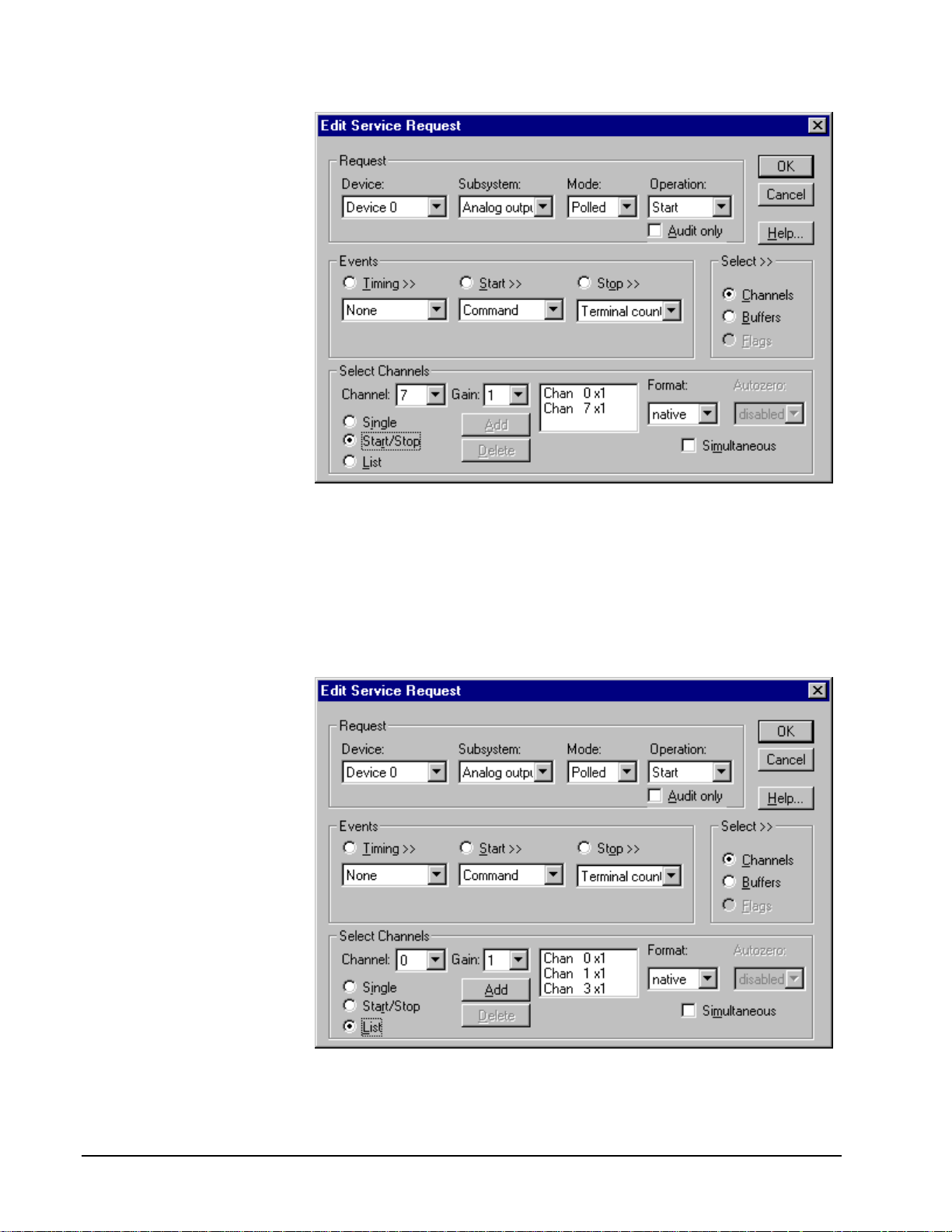
How to set up the KPCI-3130 S eri es for writing to a consec utive range of channels.
Multi-channel Analog Output List
In multi-channel list mode, the KPCI-3130 Series writes data to an arbitrary list of
analog channels.
• For the KPCI-3130 Series, a channel cannot appear more than once in
the list.
How to set up the KPCI-3130 S eri es to write to an arbitrary li st of channels.
40 • Using the KPCI-3130 Series with DriverLINX Keithley KPCI-3130 Series
Page 41

Analog Output Channel Gains
The KPCI-3130 Series models support a single analog output range. The following
table shows the correspondence between DriverLINX gains, the maximum output
signal range, and the gain code for each output range. Note: DriverLINX uses a
negative (-) gain value to signify a bipo lar (±) range.
Gain Range Gain Code
-1 ±10 V 0
Gains, Ranges, and Gain Codes for t he KPCI-3130 Series.
Use the DriverLINX Gain2Code method to easily convert between the gains in the
above table and hardware Gain Codes.
Special Flags for Channels
On the KPCI-3130 Series, each analog output channel in a task can have several
independent configuration options. DriverLINX uses special flags in the channel’s
gain property to indicate these options. For the KPCI-3130 Series the option are:
• Coupling—DC or ground
• DAC overload monitoring control
The KPCI-3130 Series provides remote differential sensing lines for each analog
output channel to determine when the voltage across the load does not match the
output voltage. DriverLINX allows you to control how an analog output task affects
DAC Overload monitoring using special flags in a channel’s gain property. (For a
complete list of DAC overload monitoring options, see “Checking for DAC
Overload” on page 44.)
Flag Set Meaning Clear Meaning (Default)
CHAN_COUPLING_DC
(2 * 2^11)
CHAN_COUPLING_GND
(3 * 2^11)
NO_OVLD_CLR (2^3)
+ CHAN_OEM_FLAG (2^15)
Uses the DC coupling mode. Uses the default coupling mode for
the device (DC for the KPCI-3130
Series).
Grounds the output pins. Uses the default c oupling mode for
the device (DC for the KPCI-3130
Series).
Does not clear the channel’s
overload status. Until it is cleared by
a digital output task, this channel can
be monitored for DAC overload only
by polling with a digital input task.
To use a gain flag, simply determine gain code for the desired gain using
Gain2Code and then add the applicable flags.
Clears the channel’s overload status.
This enables DAC overload
monitoring for this channel by a
paced digital input task.
Page 42
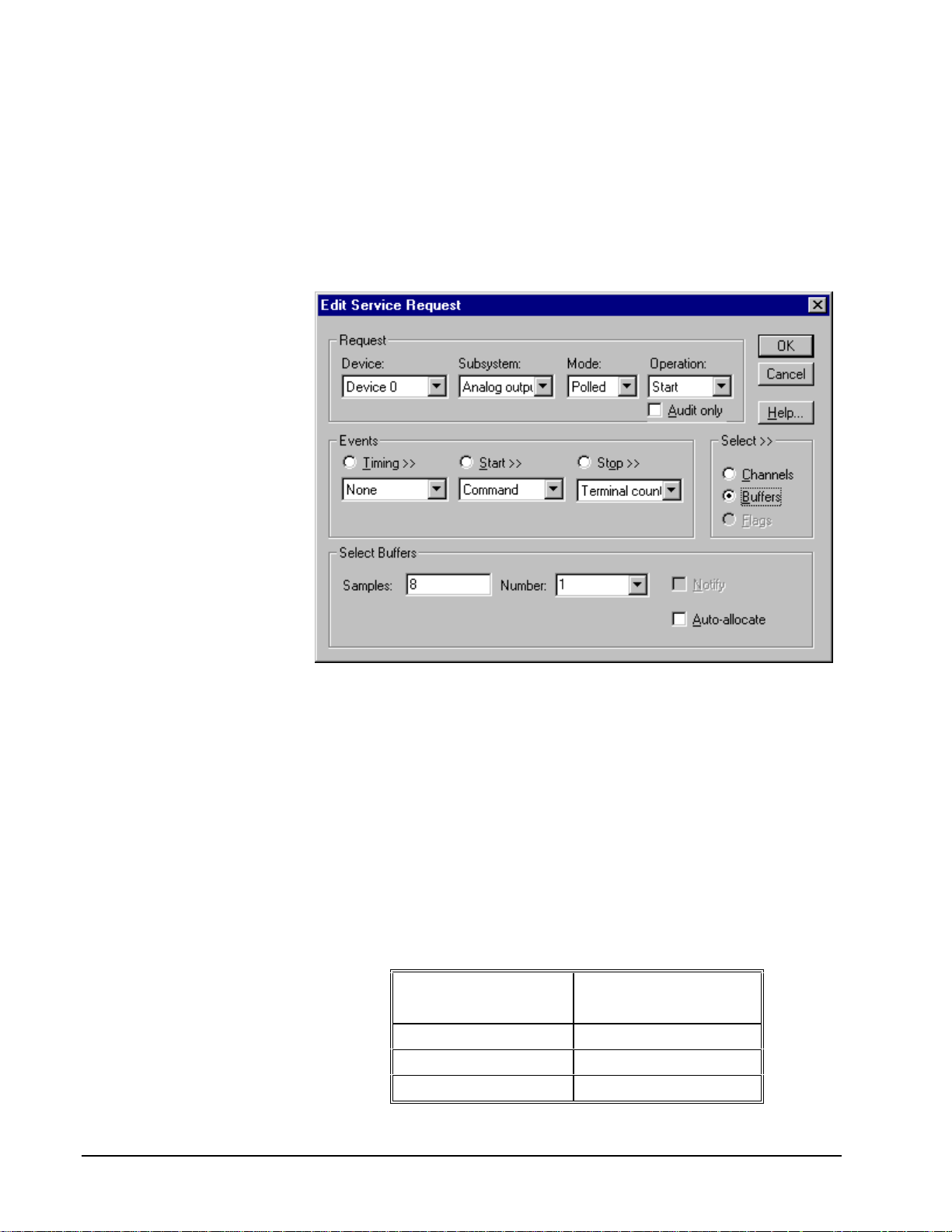
Analog Output Buffers
DriverLINX supports single-value and single-scan analog output.
• For single-value output, specify the Number of buffers as 0. The
buffer for a single value is the ioValue property.
• For a single-scan output, specify the Number of buffers as 1 and the
number of Samples equal to the number of channels in the channel
range or list.
How to set up the KPCI-3130 Series to store samples in buffers.
Buffer Size
For the single-scan analog output that the KPCI-3130 Series supports, an analog
output task can have only one buffer and it must hold exactly one scan of the
channels in the channel range or list. Each sample occupies two or four bytes,
depending on t he emulated resolution.
Analog Output Data Coding
KPCI-3130 Series uses a right-shifted, two’s complement binary format to encode
analog output data, as shown in the following table. DriverLINX refers to this coding
scheme as the “native” format.
Analog Output
Resolution
12 bits -4096 to 4095
16 bits -32768 to 32767
20 bits -524288 to 524287
Native Analog Output hardware c odes for the KPCI-3130 Series.
Analog Output
Hardware Code
42 • Using the KPCI-3130 Series with DriverLINX Keithley KPCI-3130 Series
Page 43

15
10
5
0
-5
-10
-15
-524288 0 524287
KPCI-3130 Series native A nal og Output Codes versus Voltage with a resolution of 20 bits.
20-bit
Resolution
DriverLINX refers to the default hardware analog-coding scheme as the “native”
format. For computer arithmetic in a hi gher level language, the 16-bit two’s
complement short integer or 32-bit two’s complement long integer format is
generally easier to use. Applications can use DriverLINX’s data conversion
operations to transform an entire data buffer from many common integer and
floating-poi nt formats to native format.
Page 44

Analog Output Messages
For analog output operations, DriverLINX can report the following messages to the
application:
DriverLINX
Explanation
Message
Service Start DriverLINX has started the acquisition task.
Service Done DriverLINX has completed the acquisition task.
Critical Error DriverLINX has encountered an unexpected hardware
or software condition.
DriverLINX Event mess ages for analog output.
For detailed explanations of these messages see one of the following references:
• DriverLINX Technical Reference Manual for C/C++ users
• DriverLINX/VB Technical Reference Manual for VB or Delphi users
Checking for DAC Overload
The KPCI-3130 Series provides remote differential sensing lines for each analog
output channel to determine when the voltage across the load does not match the
output voltage. DriverLINX offers several techniques to check for such a DAC
overload. An application can:
• Status poll at any time after settling
To check for DAC overload, simply sample digital input channel 4 or 5.
(See “Special Flags” on page 41.)
• Acquire a sample from the DAC overload status register upon each
overload that the board detects
To sample upon DAC overload, set up a paced task in the digital input
subsystem that samples digital input channel 4 or 5. (See “Digital Input
Timing Events” on page 46, “Digital Input Start Events” on page 48
and “Digital Input Stop Events” on page 50).
44 • Using the KPCI-3130 Series with DriverLINX Keithley KPCI-3130 Series
Page 45

Digital Input Subsystem
The following sections describe how DriverLINX implements Digital Input
Subsystem features for the KPCI-3130 Series.
Digital Input Modes
The Digital Input Subsystem supports the following modes:
• Polled—For single-value or scan digital input samples.
• Interrupt—For buffered transfers using programmed I/O.
• Other—For subsystem initialization.
Digital Input Operations
The KPCI-3130 Series Digital Input Subsystem supports the following DriverLINX
operations:
• Initialize—aborts any active interrupt data-acquisition tasks and stops
• Configure—assigns a configurable digital channel to the input
the clock. DriverLINX prevents one application from interfering with
another application’s data-acquisition tasks.
subsystem.
• Start—initiates a data-acquisition task using the Mode, Timing, Start,
and Stop Events, the Logical Channels, and the Buffers the application
specified in the Service Request.
• Status—reports the buffer position of the next sample that DriverLINX
will write into a buffer.
• Stop—terminates a digital input data-acquisition task.
• Message—DriverLINX displays a pop-up dialog box for the user
containing the text for the current DriverLINX error message.
Digital Channel Configuration
Model KPCI-3130 supports four configurable digital channels. To use them as inputs
you must first assign them to the Digital Input Subsystem using the “Configure
DriverLINX Device Dialog” (page 12) or by using a Configure operation. Only
channels 0 through 3 are configur able.
To configure a digital channel submit a service request with following settings:
• Subsystem—Digital Input or Digital Output
• Mode—Other
• Operation—Configure
• Timing Event—DIO Setup
• DIO Setup Channel—Channel number
• DIO Setup Mode—DIO BASIC
Page 46

Example: For a programming example, see DIOCNFIG in your DrvLINX4\Source
folder.
Digital Input Pacing, Tr i ggering and Gating
Options
The KPCI-3130 Series’ 32-bit digital input/output lines are designed for polled
operation only. However, as the KPCI-3130 Series User’s Manual describes, a DAC
overload can raise an interrupt. DriverLINX models this interrupt as an external
digital trigger and external pacing clock of tasks that read the DAC overload register.
Digital Input Timing Events
Timing Events specify how the hardware paces or clocks the reading of Digital Input
samples. DriverLINX uses the Timing Event to program when the KPCI-3130 Series
reads the next sample from the digital input subsystem.
For the KPCI-3130 Series, a timed digital input task can sample only the DAC
overload register channels (4 and 5). It is paced by changes in the DAC overload
status.
The KPCI-3130 Series supports the following Timing Events:
• None—Input requires no pacing as DriverLINX i s reading only a single
value.
• Rate—DriverLINX models the DAC overload interrupt as an external
clock for compatibility with applications written for other hardware.
• Digital—DriverLINX uses the DAC overload interrupt to pace the
acquisition of each sample.
None or Null Timing Event
The Null Event specifies that the task does not need a clock to determine when to
read the next sample.
Rate Timing Event
The KPCI-3130 Series supports only the Rate Generator mode for Rate Events for
digital input:
• Rate Generator—Generates a fixed rate clock with equal time
intervals between tics.
Rate Generator: External Clocki ng
An externally clocke d Rate Generator produces a rate clock with unknown time
intervals between tics.
Period (ext clk)
46 • Using the KPCI-3130 Series with DriverLINX Keithley KPCI-3130 Series
Page 47

Use an externally clocked rate generator when you want to synchronize digital input
samples with a recurrent external signal.
For the KPCI-3130 Series, a timed digital input task can sample only the DAC
overload register channels (4 and 5). It is paced by changes in the DAC overload
status.
How to set up the KPCI-3130 for fixed rate sampling using an ext ernal clock.
• Specify external clocking using a Rate Generator on Logical Channel
0 with an External or External+ Clock source. External and
External+ both specify sampling on a DAC overload condition.
• Users should connect the sense lines (SnH and SnL) for each analog
output channel being monitored.
• Specify a Period between 1 and
1232− tics that estimates the interval
between external clocks pulses (DAC overloads). For the KPCI-3130, a
tics is 1 µs. (This value is currently only for compatibility with other
drivers, where DriverLINX may use the Period value to optimize data
transfer between the driver and the application.)
• The Gate property is not applicable to the KPCI-3130; Values of
Disabled and NoConnect are accepted.
• The channel list can contain only digital input channels 4 and/or 5.
• If the start event is a digital event then the start event mask determines
which DAC channels pace the sampling for the task. Otherwise,
overloads on any channel in-use channel pace the sampling. For greater
flexibility in specifying which DAC overloads to use for pacing, use a
“Digital Timing Event” (see page 48).
Page 48

Digital Timing Event
DriverLINX supports Digital Events as aliases for externally clocked Rate
Generators. Use this technique for compatibility with data-acquisition products that
only support external clock sources.
For the KPCI-3130 Series, a timed digital input task can sample only the DAC
overload register channels (4 and 5). It is paced by changes in the DAC overload
status.
How to set up the KPCI-3130 for external rate sampling using a digit al event.
Digital Timing Events contain mask, pattern, and match fields. The mask is logically
ANDed with the digital input data on the Logical Channel and then compared against
the pattern for a match/mismatch.
• Specify external clocking using Logical Channel 4 or 5.
• Specify the Mask property with bits set for the corresponding DAC
channel to indicate that DriverLINX should sample upon each overload
of these DAC channels.
• Specify the Match property as Equals.
• Specify the Pattern property as a subset of the Mask.
• Users should connect the sense lines (SnH and SnL) for each analog
output channel in the Mask.
Digital Input Start Events
Start Events specify when the KPCI-3130 Series hardware starts reading digital input
data.
The KPCI-3130 Series supports the following Start Events for digital input:
48 • Using the KPCI-3130 Series with DriverLINX Keithley KPCI-3130 Series
Page 49

• None—Use this event when the DriverLINX operation doesn’t require
a Start Event.
• Command—DriverLINX starts the task on software command, i.e., as
soon as DriverLINX finishes programming the KPCI-3130 hardware
for the task.
• Digital—The KPCI-3130 starts acquiring digital input samples when
the board detects overloads in selected DAC channels.
None or Null Start Event
The Null Event specifies that the task does not need a Start Event to begin the task.
Command Start Event
The Command Event starts data acquisition as soon as DriverLINX has completed
programming the KPCI-3130 Series hardware with the task parameters.
Post-Trigger Sampling with a Digital Event
The KPCI-3130 Series can acquire digital input samples after a digital trigger
condition. Use post-triggering when you want to synchronize the start of data
acquisition with an external signal.
A Digital Start Event requires
an external timing source
because the KPCI-3130 does
not have a hardware clock.
How to set up the KPCI-3130 for post-triggered digital input.
Digital Start Events contain mask, pattern, and match fields. The mask is logically
AND with the digital input data on the Logical Channel and then compared against
the pattern for a match/mismatch.
Page 50

• Specify the Logical Channel as 4 or 5. DriverLINX checks for the Start
Event condition whenever the board raises a DAC overload interrupt.
• Specify the Mask property to indicate that DriverLINX should only
compare selected bits in the digital input value against the Pattern
property.
• Users should connect the sense lines (SnH and SnL) for each analog
output channel in the Mask.
• Specify the Match property as Equals triggers on any difference
between the masked digital input and the Pattern.
• Specify the Pattern property to compare with the masked digital input
value.
• The Delay property is not applicable to the KPCI-3130 Series; specify
the value as 0.
Digital Input Stop Events
Stop Events specify when the KPCI-3130 Series hardware stops reading digital input
data.
The KPCI-3130 Series supports the following Stop Events for digital input:
• None—Use this event when the DriverLINX operation doesn’t require
a Stop Event.
• Command—Dr iverLINX stops the task on software command, i.e.,
when the application issues a Service Request with a Stop operation.
• Terminal count—DriverLINX stops the task after the KPCI-3130
Series hardware has filled all the data buffers once.
• Digital—The KPCI-3130 Series stops the task when the board detects
that the digital input satisfies the condition specified in the Stop Event.
None or Null Stop Event
The Null Event specifies that the task does not need a Stop Event to end the task.
Command Stop Event
The Command Event stops data acquisition when the user application changes the
Operation property in the Service Request to Stop and resubmits the Service Request
to DriverLINX.
In Stop-on-Command mode , DriverLINX continuously cycles through al l the data
buffers, reading from the digital port on the KPCI-3130 Series.
Terminal Count Stop Event
The Terminal Count Event stops data acquisition after DriverLINX has read the
digital input data into all the data buffers once. Use terminal count when you want to
read a fixed amount of data.
50 • Using the KPCI-3130 Series with DriverLINX Keithley KPCI-3130 Series
Page 51

Pre-Trigger Sampling with a Digital Event
The KPCI-3130 can acquire digital input samples until the hardware detects a digital
trigger condition. Use pre-triggering when you want to synchronize the end of data
acquisition with an external signal.
A Digital Stop Event requires
an external timing source
because the KPCI-3130 does
not have a hardware clock.
How to set up the KPCI-3130 for pre-triggered digital input.
Digital Stop Events contain mask, pattern, and match fields. The mask is logically
AND with the digital input data on the Logical Channel and then compared against
the pattern for a match/mismatch.
• Specify the Logical Channel as 4 or 5. DriverLINX checks for the Start
Event condition whenever the board raises a DAC overload interrupt.
• Specify the Mask property to indicate that DriverLINX should only
compare selected bits in the digital input value against the Pattern
property. The Mask must be a subset of the analog output channels
monitored for the timing event (see “Digital Timing Event” on page 48
or “Rate Generator: External Clocking” on page 46).
• Specify the Match property as Equals to trigger on an exact match of
the digital pattern to the masked digital input.
• Users should connect the sense lines (SnH and SnL) for each analog
output channel in the Mask.
• Specify the Pattern property to compare with the masked digital input
value.
• The Delay property is not applicable to the KPCI-3130 Series; specify
the value as 0.
Page 52

Digital Input Channels
The KPCI-3130 Series allows applications to specify the digital channels using three
techniques:
• Start Channel—Acquire data from a single channel.
• Start/Stop Channel Range—Acquire data from a consecutive range of
channels.
• Channel List—Acquire data from a list of channels.
Digital Input Logical Channels
The KPCI-3130 Series supports both fixed and configurable digital channels.
DriverLINX defines the following Logical Channels for the KPCI-3130 Series
Digital Input Subsystem:
Model KPCI-3130
Logical
Channel
0 Digital Input/Output Bit 0, DGND … Bit 7, DGND
1 Digital Input/Output Bit 8, DGND … Bit 15, DGND
2 Digital Input/Output Bit 16, DGND … Bit 23, DGND
3 Digital Input/Output Bit 24, DGND … Bit 31, DGND
4 Digital Input/Output
5 Reserved
6 External Clock
7 External Trigger
Model KPCI-3132
Logical
Channel
DriverLINX
Function
(read DAC overload
flags)
(sample on DAC
overload)
(trigger on DAC
overload)
DriverLINX
Function
KPCI-3130 Series External
Connector
S1H,S1L … S8H, S8L
S1H,S1L … S8H, S8L
S1H,S1L … S8H, S8L
KPCI-3130 Series External
Connector
0 Reserved
1 Reserved
2 Reserved
3 Reserved
4 Digital Input/Output
(read DAC overload
flags)
5 Reserved
6 External Clock S1H,S1L … S2H, S2L
52 • Using the KPCI-3130 Series with DriverLINX Keithley KPCI-3130 Series
S1H,S1L … S2H, S2L
Page 53

(sample on DAC
overload)
7 External Trigger
(trigger on DAC
overload)
S1H,S1L … S2H, S2L
Page 54

Single Channel Digital Input
In single channel mode, the KPCI-3130 Series acquires all data from one channel.
How to set up the KPCI-3130 S eri es for sampling on a single channel.
Multi-channel Digital Input Range
In multi-channel range mode, the KPCI-3130 Series acquires all data from a
consecutive range of digital channels.
• The Stop Channel must be greater than the Start Channel.
54 • Using the KPCI-3130 Series with DriverLINX Keithley KPCI-3130 Series
Page 55
How to set up the KPCI-3130 S eri es for sampling on a consecutiv e range of channels.
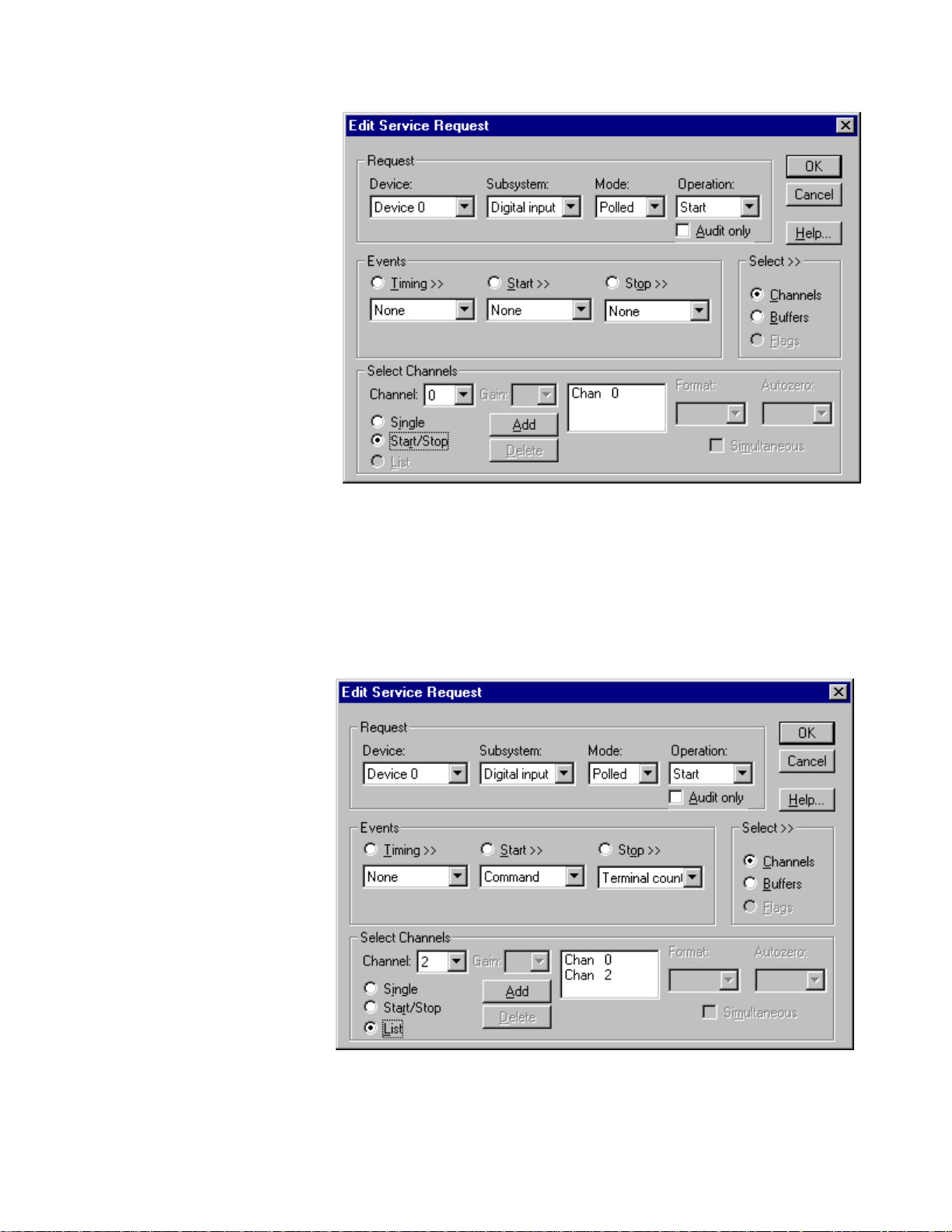
Multi-channel Digital Input List
In multi-channel list mode, the KPCI-3130 Series acquires all data from an arbitrary
list of digital channels.
How to set up the KPCI-3130 S eri es to sample from an arbitrary list of channels.
Page 56

Digital Input Buffers
DriverLINX supports single-value, single-scan and buffered digital input.
• For single-value input, specify the Number of buffers as 0. The buffer
for a single value is the ioValue property.
• For single-scan input, specify the Number of buffers as 1 and the
number of Samples equal to the number of channels.
• For buffered input, specify the Number of buffers from 1 to 255 and
the number of Samples as desired.
How to set up the KPCI-3130 S eri es to read digital samples using dat a buf fers.
Buffer Usage
DriverLINX fills buffers sequentially until the task stops. During the task only
complete buffers are available to the application. Except for tasks that stop on
terminal count, the last buffer may be only partially full. Use a Status operation to
determine the location of the last sample.
56 • Using the KPCI-3130 Series with DriverLINX Keithley KPCI-3130 Series
Page 57

Digital Input Messages
For digital input operations, DriverLINX can report the following messages to the
application:
DriverLINX
Explanation
Message
Service Start DriverLINX has started the acquisition task.
Service Done DriverLINX has completed the acquisition task.
Buffer Filled D r iverLINX has filled a digital input buffer.
Start Event DriverLINX has processed the interrupt for the start
event.
Stop Event DriverLINX has processed the interrupt for the stop
event.
Data Lost DriverLINX has detected a digital input data overrun
condition.
Critical Error DriverLINX has encountered an unexpected hardware
or software condition.
DriverLINX Event mess ages for digital input.
For detailed explanations of these messages see one of the following references:
• DriverLINX Technical Reference Manual for C/C++ users
• DriverLINX/VB Technical Reference Manual for VB or Delphi users
Page 58

Digital Output Subsystem
The following sections describe how DriverLINX implements Digital Output
Subsystem features for the KPCI-3130 Series.
Digital Output Modes
The Digital Output Subsystem supports the following modes:
• Polled—For single-value digital output samples.
• Other—For subsystem initialization.
Digital Output Operations
The KPCI-3130 Series Digital Output Subsystem supports the following DriverLINX
operations:
• Initialize—aborts any active interrupt data-acquisition tasks and stops
the clock. DriverLINX prevents one application from interfering with
another application’s data-acquisition tasks.
• Start—initiates a data-acquisition task using the Mode, Timing, Start,
and Stop Events, the Logical Channels, and the Buffers the application
specified in the Service Request.
• Message—DriverLINX displays a pop-up dialog box for the user
containing the text for the current DriverLINX error message.
Digital Output Initialization
By default, the Digital Output subsystem writes zero into the digital output port. You
can specify a different initial output value using the Configure DriverLINX Device
dialog. See “Digital Output Subsystem Page” on page 21.
Digital Channel Configuration
The KPCI-3130 supports several configurable digital channels. To use them as
outputs you must first assign them to the Digital Output Subsystem using the
“Configure DriverLINX Device Dialog” (page 12) or by using a Configure operation.
See “Digital Channel Configuration” on page 45 for more information on the
configure op eration.
58 • Using the KPCI-3130 Series with DriverLINX Keithley KPCI-3130 Series
Page 59

Digital Output Pacing, Triggering and Gating
Options
The KPCI-3130 Series’ 32-bit digital input/output lines are designed for polled
operation only. Therefore, DriverLINX allows only polled single-value or single-scan
operations without any pacing, triggering or gating.
Digital Output Timing Events
Timing Events specify how the hardware paces or clocks writing Digital Output
samples. DriverLINX uses the Timing Event to program when the KPCI-3130 Series
writes the next digital output sample from the port.
The KPCI-3130 Series supports the following Timing Events:
• None—Output requires no pacing as DriverLINX is writing only a
single value or single scan.
None or Null Timing Event
The Null Event specifies that the task does not need a clock to determine when to
write the next sample.
Page 60

Digital Output Start Events
Start Events specify when the KPCI-3130 Series hardware starts writing digital
output data.
The KPCI-3130 Series supports the following Start Events for digital output:
• None—Use this event when the DriverLINX operation doesn’t require
a Start Event.
• Command—DriverLINX starts the task on software command, i.e., as
soon as DriverLINX finishes programming the KPCI-3130 hardware
for the task.
None or Null Start Event
The Null Event specifies that the task does not need a Start Event to begin the task.
Command Start Event
The Command Event starts data acquisition as soon as DriverLINX has completed
programming the KPCI-3130 Series hardware with the task parameters.
Digital Output Stop Events
Stop Events specify when the KPCI-3130 Series hardware stops writing digital
output data.
The KPCI-3130 Series supports the following Stop Events for digital output:
• None—Use this event when the DriverLINX operation doesn’t require
a Stop Event.
• Terminal count—DriverLINX stops the task after the KPCI-3130
Series hardware has written all the data buffers once.
None or Null Stop Event
The Null Event specifies that the task does not need a Stop Event to end the task.
Terminal Count Stop Event
The Terminal Count Event stops data acquisition after DriverLINX has written the
digital output data from all the data buffers once. Use terminal count when you want
to write a fixed amount of data.
Digital Output Channels
The KPCI-3130 Series allows applications to specify the digital channels using three
techniques:
• Start Channel—Acquire data from a single channel.
• Start/Stop Channel Range—Acquire data from a consecutive range of
channels.
• Channel List—Acquire data from a list of channels.
60 • Using the KPCI-3130 Series with DriverLINX Keithley KPCI-3130 Series
Page 61

Digital Output Logical Channels
The Digital Output subsystem has a 32-bit digital input/output port that DriverLINX
models as four 8-bit Logical Channels (model KPCI-3130 only), as well as one or
two 8-bit Logical Channel to reset bits in the DAC overload register. DriverLINX
maps these signals to Logical Channels as shown in the following table:
Models KPCI-3130
Logical
Channel
0 Digital Input/Output Bit 0, DGND … Bit 7, DGND
1 Digital Input/Output Bit 8, DGND … Bit 15, DGND
2 Digital Input/Output Bit 16, DGND … Bit 23, DGND
3 Digital Input/Output Bit 24, DGND … Bit 31, DGND
4 Digital Input/Output
Models KPCI-3132
Logical
Channel
0 Reserved
1 Reserved
2 Reserved
3 Reserved
4 Digital Input/Output
How DriverLINX maps digital output hardware channels to Logical Channel s.
DriverLINX
Function
(reset DAC overload
flags)
DriverLINX
Function
(reset DAC overload
flags)
KPCI-3130 Series External
Connector
S1H,S1L … S8H, S8L
KPCI-3130 Series External
Connector
S1H,S1L … S2H, S2L
Notes:
• If a channel is configured for output, reading i t using the Digital Inp ut
subsystem returns the last value written.
• Applications can assign a configurable channel to either subsystem
using a Configure operation. (See “Digital Channel Configuration” on
page 45.)
Single Channel Digital Output
In single channel mode, the KPCI-3130 Series writes all data from one channel.
Page 62

How to set up the KPCI-3130 S eri es for writing to a single c hannel .
Multi-channel Digital Output Range
In multi-channel range mode, the KPCI-3130 Series acquires all data from a
consecutive range of digital channels.
• The Stop Channel must be greater than the Start Channel.
How to set up the KPCI-3130 S eri es for writing to a consec utive range of channels.
62 • Using the KPCI-3130 Series with DriverLINX Keithley KPCI-3130 Series
Page 63

Multi-channel Digital Output List
In multi-channel list mode, the KPCI-3130 Series acquires all data from an arbitrary
list of digital channels.
How to set up the KPCI-3130 S eri es to write to an arbitrary li st of channels.
Page 64

Digital Output Buffers
DriverLINX supports single-value and single-scan digital output.
• For single-value output, specify the Number of buffers as 0. The
buffer for a single value is the ioValue property.
• For single-scan output, specify the Number of buffers as 1 and the
number of Samples equal to the number of channels.
How to set up the KPCI-3130 Series to store samples in buffers.
Digital Output Messages
For digital output operations, DriverLINX can report the following messages to the
application:
DriverLINX
Message
Service Start DriverLINX has started the acquisition task.
Service Done DriverLINX has completed the acquisition task.
Critical Error DriverLINX has encountered an unexpected hardware
For detailed explanations of these messages see one of the following references:
• DriverLINX Technical Reference Manual for C/C++ users
• DriverLINX/VB Technical Reference Manual for VB or Delphi users
Explanation
or software condition.
DriverLINX Event mess ages for digital output.
64 • Using the KPCI-3130 Series with DriverLINX Keithley KPCI-3130 Series
Page 65

Page 66

Counter/Timer Subsystem
DriverLINX defines a counter/timer system for the KPCI-3130 Series only to model
sampling on a DAC overload condition. For information on how to set up a digital
input task to sample on a DAC overload condition, see “Digital Input Timing Events”
on page 46. For a list of all DAC-overload monitoring techniques see “Checking for
DAC Overload” on page 44.
66 • Using the KPCI-3130 Series with DriverLINX Keithley KPCI-3130 Series
Page 67

Uninstalling DriverLINX
How do I uninstall DriverLINX?
DriverLINX consists of three separate component installations:
• DriverLINX for Keithley KPCI-3130 Series
• DriverLINX Programming Interfaces
• DriverLINX Documentation
You can uninstall the last two installations at any time without interfering with
compiled applications that require DriverLINX drivers. To uninstall the latter
components, run the “Add/Remove Programs” tool in the Windows Control Panel.
To uninstall DriverLINX drivers for the Keithley KPCI-3130 Series, you must
• Disable the DriverLINX driver.
• Shut down your computer to remove the hardware.
• Reboot your computer to unload the driver.
• Run the DriverLINX uninstall program.
How to Disable a DriverLINX Driver in Windows NT
1. From the Windows Start menu, select “Settings”, then “Control Panel”.
Left click on the DriverLINX Configuration icon in the Control Panel.
2. Select the KPCI-3130 Series devices you want to disable.
3. Right click on each device and select “Disabled” on the popup menu.
4. Repeat steps 2-3 for each KPCI-3130 card that you are uninstalling.
5. Close the DriverLINX Configuration Panel.
6. When finished, shut down your computer and physically remove any
installed KPCI-3130 hardware.
7. Reboot Windows.
8. To finish uninstalling, see “How to Remove DriverLINX for Keithley
KPCI-3130 Series” on page 69.
Keithley KPCI-3130 Series Uninstalling DriverLINX • 67
Page 68

How to Disable a DriverLINX Driver in Windows 95/98
1. From the Windows Start menu, select “Settings”, then “Control Panel”.
Left click on the System icon in the Control Panel. Select the “Device
Manager” tab in the System Properties dialog.
2. Left click the “+” icon next to “DriverLINX drivers” to display the
installed Keithley KPCI-3130 devices.
3. Select the KPCI-3130 Series device you want to disable.
4. Click the “Remove” button.
5. In the “Confirm Device Removal” dialog, select “OK”.
6. Repeat steps 3-5 for each KPCI-3130 Series card or driver that you
uninstalling.
7. When finished, click “Close”, shut down your computer, and physically
remove any installed KPCI-3130 hardware.
8. Reboot Windows.
9. To finish uninstalling, see “How to Remove DriverLINX for Keithley
KPCI-3130 Series” on page 69.
68 • Uninstalling DriverLINX Keithley KPCI-3130 Series
Page 69

How to Remove DriverLINX for Keithley KPCI-3130 Series
1. From the Windows Start menu, select “Settings”, then “Control Panel”.
Left click on the Add/Remove Programs icon in the Control Panel.
2. Select “DriverLINX for Keithley KPCI-3130 Series” in the
Add/Remove Programs Properties dialog.
3. Click the “Add/Remove…” button.
4. Answer “Yes” to “Are you sure you want to remove ‘DriverLINX for
Keithley KPCI-3130 Series’ and all of its components?” in the Confirm
File Deletion dialog.
5. The DriverLINX uninstall program will proceed.
The uninstall program will not remove the folder, “\DrvLINX4\System”. This folder
contains copies of any \Windows\System or \Windows\System32 files that the
original DriverLINX installation updated.
Keithley KPCI-3130 Series Uninstalling DriverLINX • 69
Page 70

Page 71

Troubleshooting
Solving Problems
Correct operation of your KPCI-3130 hardware requires successful completion of
three steps.
½ Windows recognizes KPCI-3130 hardware and installs drivers.
1. You configure the KPCI-3130 drivers using the DriverLINX
Configuration Panel.
2. Windows loads the KPCI-3130 drivers into memory.
If you are having a problem installing or configuring your KPCI-3130 product,
review the following notes. If these notes do not solve your problem, or your problem
is not described, then contact technical support and fully describe your problem.
Solving Problems Recognizing and Instal ling
Drivers
Windows must recognize the KPCI-3130 hardware and then install KPCI-3130
drivers for the hardware.
• For Windows to automatically recognize the KPCI-3130 hardware, you
must install a KPCI-3130 product into your machine and restart the
computer.
• For Windows to install KPCI-3130 drivers, you must install the KPCI-
3130 driver software on the DriverLINX CD.
If you installed the KPCI-3130 hardware before you installed the DriverLINX
software, Windows 95/98/2000 may install the KPCI-3130 hardware without drivers.
To fix this, you must instruct Windows to reinstall the Plug-and-Play driver. Follow
the notes below for instructions.
Keithley KPCI-3130 Series Troubleshooting • 71
Page 72

Fixing Problems Installing Hardware Before Software on
Windows 95/98/2000
If you installed the KPCI-3130 hardware before installing the DriverLINX software,
Windows 95/98 may install the hardware incorrectly.
1. Start Windows Device Manager.
2. Search for “DriverLINX drivers”. If you do not see it, go to step 4.
3. Click on the “+” icon next to “DriverLINX drivers” and search for “PCI
Card”. If you find “PCI Card”, go to step 6, otherwise go to the next
step.
4. Search for “Other devices”.
5. Click on the “+” icon next to “Other devices” and search for “PCI
Card”.
6. Select “PCI Card”.
7. Click “Remove” in the Device Manager.
8. Highlight “Computer” in the Device Manager and click “Refresh”.
9. Windows should re-install your hardware under “DriverLINX drivers”.
10. Answer “Yes” to “Do you want to restart your computer now?”.
11. After reboo t ing your computer, you must configure DriverLINX. See
“Configuring the KPCI-3130 Series” on page 11.
Solving Problems Configuring the Dr i vers
Windows automatically assigns hardware resources for the KPCI-3130 Series, but
you must still configure the KPCI-3130 drivers before using them. The DriverLINX
configuration only requires that you assign each KPCI-3130 product a unique
Logical Device number. And, on Windows NT and Windows 2000, you must
manually select the hardware model of your KPCI-3130 Series board. See
“Configuring the KPCI-3130 Series” on page 11.
Solving Problems Loading Drivers
Before the KPCI-3130 drivers can load, you must
1. Install the DriverLINX software.
2. Install the KPCI-3130 hardware into your computer.
3. Configure Drive rLINX.
4. Reboot your computer.
If you have not completed the above steps, please do so before proceeding.
On both Windows NT and Windows 95/98, the operating system will automatically
assign hardware resources to the KPCI-3130 cards. Automatic resource assignment
can fail sometimes on
• Older PCI computers.
• Computers with ISA cards installed.
72 • Troubleshooting Keithley KPCI-3130 Series
Page 73

• Computers with no free hardware resources .
• Computers running Windows NT 4.0 with a BIOS setting designating
the operating system as Plug-and-Play Aware.
Sorting through all possibilities can be a challenge due to the she e r number of
combinations of PCI hardware designs, PC plug-in boards, and versions of Windows.
The following sections will help you gather information about why a driver may have
failed to load. This information is essential for you or technical support to solve your
problem.
Did the DriverLINX Driver Load?
1. Run “DriverLINX Configuration” from Windows Control P anel.
2. Select the “DriverLINX” tab.
3. Click the “+” icon next to DriverLINX to expand the list of drivers, if
necessary.
4. Select “Keithley KPCI-3130 Series”. Click “+”, if necessary, to expand
the list.
5. Select the line with the number of the Logical Device you configured. If
the number does not exist on Windows NT or, on Windows 95/98, you
see only a hardware d escription, you di d not configure the driver. See
“Configuring the KPCI-3130 Series” on page 11.
6. Click the “Properties…” button and then select the “General” tab.
7. Do you see “Status: Device Loaded”? If not, did you reboot the
computer after configuring? If not, reboot now and repeat the above
steps.
8. If you rebooted the computer after configuring and Windows did not
load your device, see “Checking for Device Errors” on page 73.
Checking for Device Errors
When a DriverLINX kernel driver cannot load, it usually writes an explanation into
the system event log. You can view this log under Windows 95/98 or Windows NT
using the DriverLINX Event Viewer.
Windows 95/98 maintains additional driver information in the Device Manager. Also
see “Getting More Driver Information on Windows 95/98” on page 74.
Keithley KPCI-3130 Series Troubleshooting • 73
Page 74

1. Run “DriverLINX Event Viewer” from the DriverLINX folder.
2. Click on the “+” icon next to “DriverLINX” in the left panel.
3. Select the abbreviation for your driver.
4. Does the first line in the right panel show a current error?
5. Double click on the error line to see more detail and an explanatory
message.
6. If you cannot resolve the problem yourself, please provide this error
information when contacting technical support.
Getting More Driver Information on Windows 95/98
Windows 95/98 reports additional information about device status using the Device
Manager. To access this utility,
1. Right click on “My Computer” and then select “Properties”.
2. Select “Device Manager” and “View devices by type
3. Does “DriverLINX drivers” appear in the list? If not, see “Solving
Problems Recognizing and Installing Drivers” on page 71.
4. Click the “+” next to “DriverLINX drivers”.
5. Does your KPCI-3130 product appear in the list? If not, see “Solving
Problems Recognizing and Installing Drivers” on page 71.
6. Does the icon next to your KPCI-3130 product display an exclamation
point (!)? If no, Windows has loaded your KPCI-3130 driver.
7. Select the line with the “!” and then click “Properties”.
8. The General tab will show the reason why the driver did not load.
9. The Resources tab will show if Windows detected an unresolvable
hardware conflict.
Getting More Driver Information on Windows NT
On Windows NT, the only reasons that a driver does not load are
• You did not install the driver software.
• You did not correctly configure the driver.
• You changed the driver startup parameters.
• Your BIOS set t ing designates the operating system as Plug-and-Pla y
aware. (Applies only to Window NT 4.0).
An incorrectly configured driver will report the reasons that it failed to load into the
Windows Event Log. See “Checking for Device Errors” on page 73 for more
information.
Under Windows NT 4.0, a Logical Device may not load because the operating
system does not always configure Plug-and-Play PCI devices properly. This may
result in unexpected or no Event Log entries. To work around this, set your
computer’s BIOS to configure Plug-and-Play devices before it starts the operating
system. On various computers the BIOS setting is called “Plug-and-Play Aware OS –
Disabled” or “Plug & Play OS – No”.
74 • Troubleshooting Keithley KPCI-3130 Series
Page 75

On Windows NT, DriverLINX drivers load automatically during system boot. An
administrator can change the startup command for any NT driver to either “manual”
or “disabled”.
1. Run “DriverLINX Configuration” from Windows Control P anel.
2. Select the “DriverLINX” tab.
3. Click the “+” icon next to DriverLINX to expand the list of drivers, if
necessary.
4. Select “Keithley KPCI-3130 Series”. Click “+”, if necessary, to expand
the list.
5. Select the line with the number of the Logical Device that did not load.
6. Right click the mouse to see a popup menu.
7. Select “Automatic” to instruct Windows to load the driver the next time
you reboot.
Generating a DriverLINX Configuration Report
Your DriverLINX installation includes a troubleshooting tool that generates a report
of your DriverLINX configuration. If you call Technical Support, after reading
“Solving Problems” on page 71, they may ask you to generate and e-mail this report
to help you solve installation and configuration problems.
What is in the Report?
The troubleshooting tool analyzes your computer to obtain information about
DriverLINX and operating system software that would assist Technical Support in
troubleshooting a problem you are having. It i ncludes information on DriverLIN X
files, environment variables, registry entries, hardware and the operating system.
How do I Generate the Repor t?
You can easily generate the report by clicking this shortcut . Once the
troubleshooting tool generates the report, you will have the opportunity to review it
and make deletions, if desired, before e-mailing it to Technical Support. If you do not
have direct access to e-mail, you can save the report to a disk file and send a copy
Keithley KPCI-3130 Series Troubleshooting • 75
Page 76

later. A Technical Support engineer will guide you through these steps when you are
asked to send a report.
76 • Troubleshooting Keithley KPCI-3130 Series
Page 77

Glossary of Terms
CHAN_OEM_FLAG
A flag that you add to a gain code to indicate that you are using OEM-specific gain
flags. (=2^15)
A/D
Abbreviation for Analog-to-Digital, a process that converts a continuous analog
signal into a discrete digital approximation of the analog signal.
ADC
Abbreviation for Analog-to-Digital Converter, the hardware that performs the A/D
conversion.
API
Abbreviation for Application Programming Interface. An API defines the syntax of
the data structures and functions of software services.
Buffer
A block of memory used to receive data from a data-acquisition device or to write
data to a data-acquisition device.
Bus mastering
Bus mastering is a mode that PCI devices use to perform DMA data transfers. Bus
mastering requires a compatible PCI device and motherboard. The KPCI-3130 Series
and most motherboards support bus mastering.
Clocking
A periodic pulse or signal that data-acquisition hardware uses to read or write the
next sample or block of samples. Also referred to as “pacing”.
D/A
Abbreviation for digital-to-analog, a process that converts a discrete digital value into
a continuous analog voltage representing that value.
Keithley KPCI-3130 Series Glossary of Terms • 77
Page 78

DAC
Abbreviation for digital-to-analog converter, the hardware that performs the D/A
conversion process.
DMA
Abbreviation for Direct Memory Access, a technique where the system board can
transfer data between a device and memory without using the CPU. In the PC, a
standard chip on the system board controls the transfer.
Event
For DriverLINX, an event is the occurrence of a signal that clocks, starts, or stops a
data-acquisition task.
In an ActiveX control, an event is a procedure in the client application called by the
control.
Gating
A signal that enables and disables another signal or data-acquisition task depending
on the value of the gate signal.
IRQ
Abbreviation for interrupt request. Peripheral hardware signals the CPU that it is
ready to transfer data.
ISR
Abbreviation for interrupt service routine, the software function inside a device
driver that handles interrupt requests.
Logical Device
DriverLINX’s designation for a specific data-acquisition board inside your computer.
Messages
In Windows and DriverLINX, a message notifies the application about the state of a
process. In DriverLINX’s ActiveX controls, DriverLINXSR and DriverLINXLDD,
messages fire a control event.
Modes
DriverLINX data-acquisition techniques.
Operations
Allowed DriverLINX data-acquisition commands.
Pacing
A periodic pulse or signal that data-acquisition hardware uses to read or write the
next sample or block of samples. Also referred to as “clocking”.
78 • Glossary of Terms Keithley KPCI-3130 Series
Page 79

Process
Refers to the collection of data and code segments and hardware resources that the
operating system assigns to one application.
Scan List
The channels sampled or written by a task, whether specified using a range or a list.
Service Request
A DriverLINX object or data structure that completely defines a data-acquisition
task.
Single-scan
A task that samples once from each channel in the scan list. Such a task requires a
buffer that holds exactly one scan.
Subsystem
DriverLINX subdivides a general-purpose data-acquisition device into six
subsystems—Device, Analog Input, Analog Output, Digital Input, Digital Output,
and Counter/Timer.
Triggering
The technique of using a pulse or signal to start or stop a data-acquisition task.
TTL
Abbreviation for transistor-transistor logic, a family of digital logic elements.
Keithley KPCI-3130 Series Glossary of Terms • 79
 Loading...