

Page 1

Keithley KPCI-3108 Series
Using DriverLINX with Your
Hardware
Page 2

Information in this document is subject to change without notice. The software
described is this document is furnished under a license agreement. The software may
be used or copied only in accordance with the terms of the agreement.
SCIENTIFIC SOFTWARE TOOLS, INC. SHALL NOT BE LIABLE FOR ANY
SPECIAL, INCIDENTAL, OR CONSEQUENTIAL DAMAGES RELATED TO
THE USE OF THIS PRODUCT. THIS PRODUCT IS NOT DESIGNED WITH
COMPONENTS OF A LEVEL OF RELIABILITY SUITABLE FOR USE IN LIFE
SUPPORT OR CRITICAL APPLICATIONS.
This document may not, in whole or in part, be copied, photocopied, reproduced,
translated or reduced to any electronic medium or machine readable form without
prior written consent from Scientific Software Tools, Inc.
Keithley KPCI-3108 Series: Using DriverLINX with Your Hardware
Copyright 1999, 2002 by Scientific Software Tools, Inc.
All rights reserved.
First Printing.
SST 26-0202-1
DriverLINX, SSTNET, and LabOBJX are registered trademarks and
DriverLINX/VB is a trademark of Scientific Software Tools, Inc.
MetraByte is a trademark of Keithley Instruments, Inc.
Microsoft and Windows are registered trademarks and Visual C++ and Visual Basic
are trademarks of Microsoft Corporation.
Borland is a registered trademark and Borland C++ and Delphi are trademarks of
Borland International, Inc.
All other brand and product names are trademarks or registered trademarks of their
respective companies.
Page 3

Contents
Preface 7
Software License and Software Disclaimer of Warranty............................................................7
About DriverLINX.....................................................................................................................9
About This User’s Guide...........................................................................................................9
Conventions Used in This Manual...........................................................................................11
Configuring the KPCI-3108 Series 13
Introduction..............................................................................................................................13
Configure DriverLINX Device Dialog.....................................................................................14
Using the KPCI-3108 Series with DriverLINX 27
Introduction..............................................................................................................................27
KPCI-3108 Series Hardware Features .....................................................................................27
DriverLINX Hardware Model for KPCI-3108 Series..............................................................28
Connecting Signals to the KPCI-3108 Series...........................................................................33
Device Subsystem....................................................................................................................39
Analog Input Subsystem ..........................................................................................................40
Device Subsystem Page.............................................................................................15
Analog Input Subsystem Page ...................................................................................20
Analog Output Subsystem Page.................................................................................21
Digital Input Subsystem Page....................................................................................22
Digital Output Subsystem Page .................................................................................24
Counter/Timer Subsystem Page.................................................................................26
DriverLINX Subsystems............................................................................................28
DriverLINX Modes ...................................................................................................28
DriverLINX Operations and Events..........................................................................30
Logical Channels.......................................................................................................32
Buffers.......................................................................................................................32
Analog Input Subsystem Signals................................................................................33
Analog Output Subsystem Signals.............................................................................35
Digital Input Subsystem Signals................................................................................36
Digital Output Subsystem Signals..............................................................................37
Counter/Timer Subsystem Signals.............................................................................37
Device Modes............................................................................................................39
Device Operations .....................................................................................................39
Analog Input Modes..................................................................................................40
Analog Input Operations............................................................................................40
Analog Input Pacing, Triggering and Gating Options................................................40
Analog Input Timing Events......................................................................................42
Analog Input Start Events..........................................................................................52
Analog Input Stop Events..........................................................................................55
Analog Input Channels...............................................................................................58
Keithley KPCI-3108 Series Contents • 3
Page 4

Analog Input Expansion Channels.............................................................................64
Analog Input Buffers .................................................................................................66
Analog Input Data Coding.........................................................................................67
Analog Input Messages..............................................................................................68
Analog Output Subsystem........................................................................................................69
Analog Output Modes................................................................................................69
Analog Output Operations.........................................................................................69
Analog Output Pacing, Triggering and Gating Options.............................................69
Analog Output Timing Events...................................................................................71
Analog Output Start Events .......................................................................................81
Analog Output Stop Events........................................................................................81
Analog Output Channels............................................................................................82
Analog Output Channel Gains ...................................................................................84
Analog Output Buffers...............................................................................................85
Analog Output Data Coding.......................................................................................85
Analog Output Messages ...........................................................................................87
Digital Input Subsystem...........................................................................................................88
Digital Input Modes...................................................................................................88
Digital Input Operations.............................................................................................88
Digital Input Pacing, Triggering and Gating Options................................................89
Digital Input Timing Events.......................................................................................89
Digital Input Start Events...........................................................................................93
Digital Input Stop Events...........................................................................................93
Digital Input Channels...............................................................................................94
Digital Input Buffers..................................................................................................97
Digital Input Messages...............................................................................................98
Digital Output Subsystem.........................................................................................................99
Digital Output Modes ................................................................................................99
Digital Output Operations..........................................................................................99
Digital Output Pacing, Triggering and Gating Options............................................100
Digital Output Timing Events..................................................................................100
Digital Output Start Events......................................................................................104
Digital Output Stop Events......................................................................................104
Digital Output Channels...........................................................................................104
Digital Output Buffers.............................................................................................108
Digital Output Messages..........................................................................................108
Counter/Timer Subsystem......................................................................................................110
Counter/Timer Channel Usage.................................................................................110
Clock Sources and Modes........................................................................................111
Gate Settings............................................................................................................113
Counter/Timer Tasks ...............................................................................................113
Counter/Timer Messages.........................................................................................115
Uninstalling DriverLINX 117
How do I uninstall DriverLINX? ...........................................................................................117
Troubleshooting 121
Solving Problems...................................................................................................................121
Solving Problems Recognizing and Installing Drivers.............................................121
Solving Problems Configuring the Drivers..............................................................122
Solving Problems Loading Drivers..........................................................................122
Generating a DriverLINX Configuration Report....................................................................125
What is in the Report?..............................................................................................125
4 • Contents Keithley KPCI-3108 Series
Page 5

How do I Generate the Report?...............................................................................125
Glossary of Terms 126
Keithley KPCI-3108 Series Contents • 5
Page 6

Page 7

Preface
Software License and Software Disclaimer of Warranty
This is a legal document whic h is an agreement between you, the Licensee, and Scientific Software Tools, Inc. By opening this
sealed diskette package, Licensee agrees to bec ome bound by the terms of this Agreement, which include the S oftware License and
Software Disclaimer of Warranty.
This Agreement constit utes the complete Agreement between Licensee and Scient ific Software Tools, Inc. If Licensee does not
agree to the terms of this Agreement, do not open the dis kette package. Promptly return the unopened diskette package and the other
items (including written materials , binders or other containers, and hardware, if any) that are part of this product to S cientific Software
Tools, Inc. for a full refund. No ref unds will be given for products that have opened disk packages or missing components.
Licensing Agreement
Copyright. The software and doc umentation is owned by Scient ific Software Tools, Inc. and is prot ected by both United States
copyright laws and int ernational treaty provisions. Scient ific Software Tools, Inc. authoriz es the original purchaser only (Licensee) to
either (a) make one copy of t he software solely for backup or archival purposes, or (b) transf er the software to a si ngle hard disk only.
The written materials acc om panying the software may not be duplicated or copied for any reason.
Trade Secret. Licensee understands and agrees that the sof tware is the propriet ary and confident ial property of Scientifi c Software
Tools, Inc. and a valuable t rade secret. Li censee agrees to us e the software only for the intended us e under this License, and shall not
disclose the soft ware or i t s contents to any third part y.
Copy Restrictions. The Licensee may not modify or trans late the program or related documentation without the prior written
consent of Scientific Software Tools, Inc. All modifications, adapt ations, and me rged portions of the s oftware const itute the s oftware
licensed to t he Licensee, and the terms and conditions of this agreement apply to same. Licens ee may not distribut e copies, inc luding
electronic transfer of c opies, of the modif ied, adapted or m erged software or ac company ing written m aterials to others. Licensee agrees
not to reverse engineer, decompil e or di sassemble any part of the s of tware.
Unauthorized copying of the soft ware, including sof tware that has been m odified, merged, or i ncluded with other s oftware, or of t he
written materials is ex pressly forbidden. Licens ee may not rent, transfer or leas e the software to any third parties. Licens ee agrees to
take all reasonable steps to protect Scientific Software Tools’ software from theft, disclosure or use contrary to the terms of the Licens e.
License. Scientific S oftware Tools, I nc. grants t he Licensee only a non-exclusiv e right to use the serialized copy of the software on
a single terminal connected t o a single computer. The Licens ee may not network the s oftware or use it on more t han one computer or
computer terminal at the s ame time.
Term. This Lic ense is effective until terminated. This License will terminate automatic ally without notice from Scientific Software
Tools, Inc. if Lic ensee fail s to com ply wit h any term or c ondition of this Licens e. The Licensee agrees upon such termination to ret urn or
destroy the written materi als and all copies of t he software. The Licensee may terminate the agreement by ret urning or destroying the
program and documentation and all copies thereof.
Keithley KPCI-3108 Series Preface • 7
Page 8

Limited Warranty
Scientific Software Tools, I nc. warrants that the software will perform subs tantially in acc ordance with the written mat erials and that
the program disk, instructi onal manuals and reference mat erials are free from defec ts in materials and workmanship under normal us e
for 90 days from the date of receipt. All express or im pl i ed warranties of the software and related materials are limited to 90 days.
Except as specif icall y set f orth herein, t he soft ware and accompany ing writt en materials (includi ng instruc tions f or use) are provided
“as is” without warranty of any kind. Further, Sc ientific Soft ware Tools, Inc. does not warrant , guarantee, or make any represe ntations
regarding the use, or the results of t he use, of the s of tware or writ ten mat erial s in terms of correct ness , acc uracy , reliabil ity, currentness,
or otherwise. The entire risk as to the results and perform ance of the software is as sumed by Licensee and not by Scienti fic Software
Tools, Inc. or its distributors, agents or employees.
EXCEPT AS SET F ORTH HE REI N, THE RE ARE NO OTHER WARRANT IE S, EI THER EXPRESS OR IMPLIED, INCLUDING BUT
NOT LIMITED TO IMPLIED WARRANTIES OF MERCHANTABILITY AND FITNESS FOR A PARTICULAR PURPOSE, WITH
RESPECT TO THE SOFTWARE, THE ACCOMPANYING WRITTEN MATERIALS, AND ANY ACCOMP ANYING HARDWARE.
Remedy. Scientific S oftware Tools’ ent ire liabilit y and the Licens ee’s ex clus ive remedy shall be, at Sc ientific Sof tware Tools’ opt ion,
either (a) return of the price paid or (b) repair or replac ement of the software or accompanying m aterials. In the event of a defect in
material or workmans hip, the item may be returned wit hin the warranty period to Scientific S oftware Tools for a replacement without
charge, provided the lic ensee previously s ent in the limited warrant y registration board t o Scientific Software Tools, I nc., or can furnis h
proof of the purchase of the program. This remedy is void if failure has resulted from accident, abuse, or misapplication. Any
replacement will be warranted for the remainder of the original warranty period.
NEITHER SCIENTIFIC SOFTWARE TOOLS, INC. NOR ANYONE ELSE WHO HAS BEEN INVOLVED IN THE CREATION,
PRODUCTION, SALE OR DELI VERY OF THIS PRODUCT S HALL BE LIABLE FOR ANY DIRE CT, INDIRECT, CONSEQUENTI AL,
OR INCIDENTAL DAMAGES (INCLUDING DAMAGES FOR LOSS OF BUSINESS PROFITS, BUSINESS INTERRUPTION, LOSS OF
BUSINESS INFORMATION AND THE LIKE) ARISING OUT OF T HE USE OF OR THE INABI LITY TO USE SUCH PRODUCT EVEN
IF SCIENTIFIC SOFTWARE TOOLS HAS BEEN ADVISED OF THE POSSIBILITY OF SUCH DAMAGES. BECAUSE SOME
JURISDICTIONS DO NOT ALLOW THE EXCLUSION OR LIMITATION OF LIABILITY FOR CONSEQUENTIAL OR INCIDENTAL
DAMAGES, OR LIMITATI ONS ON DURATION OF AN IMPLIED WARRANTY, THE ABOVE LIM ITATIONS MAY NOT APPLY TO
LICENSEE.
This agreement is governed by the laws of the Commonwealth of Pennsylvania.
8 • Preface Keithley KPCI-3108 Series
Page 9

About DriverLINX
Welcome to DriverLINX for Microsoft Windows, the high-performance realtime data-acquisition device drivers for Windows application development.
DriverLINX is a language- and hardware-indepe ndent applic ation programming
interface designed to support hardware manufacturers’ high-speed analog, digital,
and counter/timer data-acquisition boards in Windows. DriverLINX is a multi-user
and multitasking data-acquisition resource manager providing more than 100 services
for foreground and background data acquisition tasks.
Included with your DriverLINX package are the following items:
• The DriverLINX API DLLs and drivers supporting your data-
acquisition hardware
• Analog I/O Panel, a DriverLINX program that verifies the installation
and configuration of DriverLINX for your analog input/output board
and demonstrates several virtual bench-top instruments
• Source code for the sample programs
• The DriverLINX Application Programming Interface files for your
compiler
• DriverLINX On-line Help System
• DriverLINX 4.0 Installation and Configuration Guide
• DriverLINX Analog I/O Programming Guide
• DriverLINX Technical Reference Manual
• Supplemental Documentation on DriverLINX and your data-acquisition
hardware
About This User’s Guide
The purpose of this manual is to help you quickly learn how to configure and use t he
hardware features of Keithley’s KPCI-3108 Series boards with DriverLINX.
• For help installing and configuring your hardware and Dr iverLINX,
please see the manual that accompanied your hardware and the
DriverLINX 4.0 Installation and Configuration Guide for your version
of Windows.
• For more information on the DriverLINX API, please see the
DriverLINX Technical Reference Manual.
• For additional help programming your board, please examine the source
code examples on the Distribution Disks.
This manual contains the following chapters:
Configuring the KPCI-3108 Series
Shows how to configure the KPCI-3108 Series using the Configure DriverLINX
Device dialog box.
Using the KPCI-3108 Series with DriverLINX
Keithley KPCI-3108 Series Preface • 9
Page 10

Shows how to set up DriverLINX with the Edit Service Request dialog box to use
KPCI-3108 Series hardware features.
Uninstalling DriverLINX
Describes how to remove DriverLINX hardware drivers and other files.
Troubleshooting
Gives troubleshooting tips for installing, configur ing, and loading D riverLINX
drivers.
10 • Preface Keithley KPCI-3108 Series
Page 11

Conventions Used in This Manual
The following notational conventions are used in this manual:
• A round bullet (•) identifies itemized lists.
• Numbered lists indicate a step-by-step procedure.
• DriverLINX Application Programming Interface and Windows macro
and function names are set in bold when mentioned in the text.
• DriverLINX indicates the exported function name of the device driver
DLL while DriverLINX indicates the product as a whole.
• DriverLINX Application Programming Interface identifiers, menu
items, and Dialog Box names are italicized when mentioned in the text.
• Italics are used for emphasis.
• Source code and data structure examples are displayed in Courier
typeface and bounded by a box with a single line.
Code
• A box with a double line bound tables of information.
Tables
Concept
• Important concepts and notes are printed in the left margin.
Keithley KPCI-3108 Series Preface • 11
Page 12

Page 13

Configuring the KPCI-3108 Series
Introduction
The installation program provides general instructions for installing and configuring
DriverLINX. This manual explains the steps and special features that apply to
Keithley’s KPCI-3108 Series boards.
Installing and configuring DriverLINX for a Keithley KPCI-3108 Series board
requires three steps:
1. Install DriverLINX. Follow the instructions given by the installation
program. The Read Me First instructions explain the components and
drivers you can install.
2. Install your KPCI-3108 hardware. Follow the instructions in your
hardware manual.
Windows NT
3. Configure DriverLINX. This creates a Logical Device, which stores
configuration information for your board. See “Configure Dri verLINX
Device Dialog” on page 14 for configuration options specific to a
Keithley KPCI-3108 Series model. Configuration is automatic under
Windows 2000/XP but you may want to customize the settings.
After installing your b oard, configuring DriverLINX, and restarting Windows (if
required), reopen the DriverLINX Configuration Panel to make sure that
DriverLINX loaded the Logical Device for your board. If the Logical Device is not
loaded, the Event Log may have a message from the driver that explains why. You
can check the Event Log using the DriverLINX Event Viewer on the Windows Start
Menu.
Under Windows NT 4.0, a Logical Device may not load because the operating
system does not always configure Plug-and-Play PCI devices properly. To work
around this, set your computer’s BIOS to configure Plug-and-Play devi ces before it
starts the operating system. On various computers the BIOS setting is called “Plugand-Play Aware OS – Disabled” or “Plug & Play OS – No”.
Keithley KPCI-3108 Series Configuring the KPCI-3108 Series • 13
Page 14
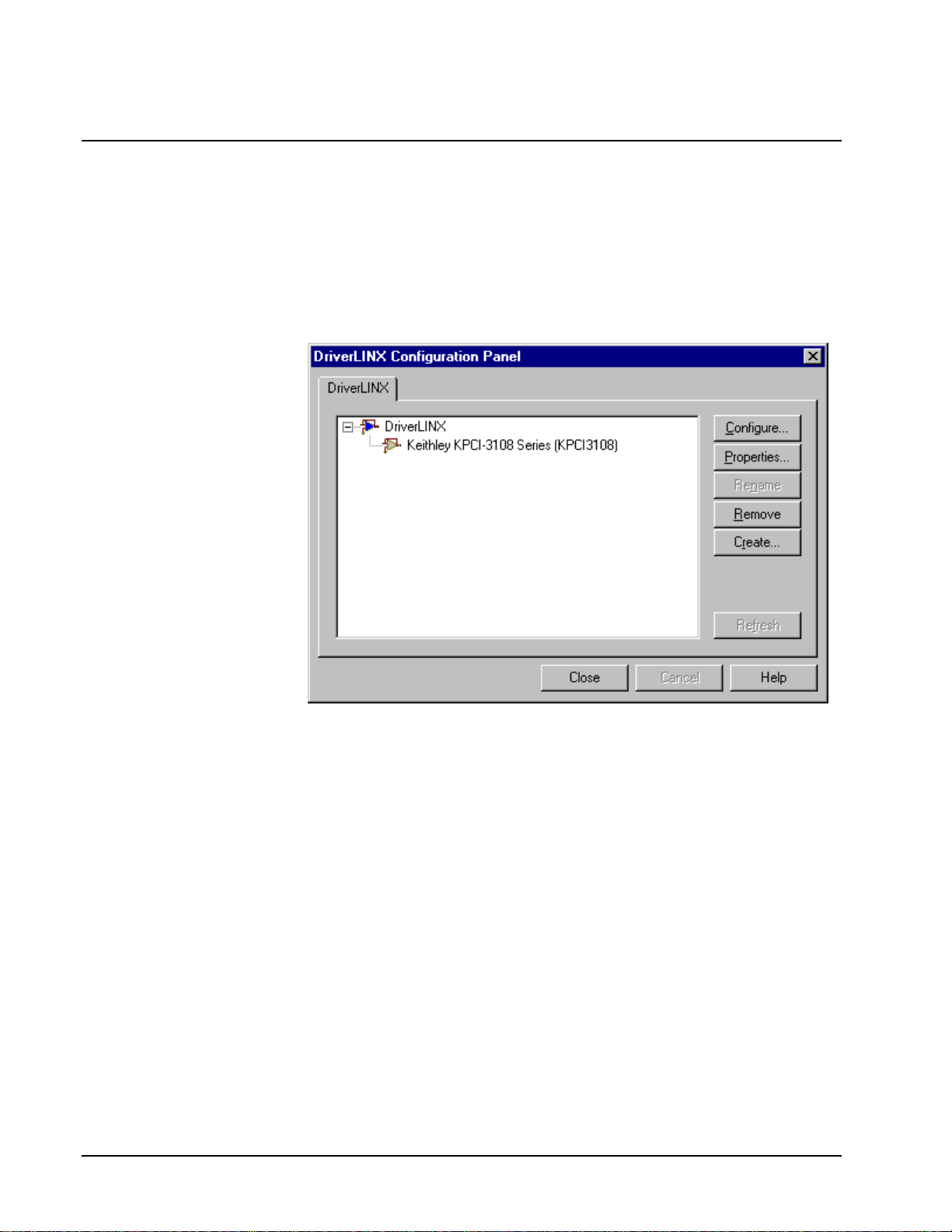
Configure DriverLINX Device Dialog
DriverLINX uses a standardized configuration protocol for all data-acquisition
hardware. Configur ation assigns an identi fying device number to a specific KPCI3108 Series board in your computer and allows you to enable or disable bus
mastering.
The installation program automatically starts the DriverLINX Configuration Panel.
To start it now, use the shortcut on the Windows Start Menu.
When you click the Configure… button on the DriverLINX Configuration Panel,
DriverLINX displays the Configure DriverLINX Device dialog. The dialog has a
page for each subsystem on the Keithley KPCI-3108 Series. The following sections
describe your choices in configuring DriverLINX to work with your board.
14 • Configuring the KPCI-3108 Series Keithley KPCI-3108 Series
Page 15

Device Subsystem Page
Use the Device subsystem page to tell DriverLINX the model name of, and,
optionally, the accessories connected to your KPCI-3108 Series board.
Vendor
The Vendor property displays “Keithley Instruments, Inc.” It is a read-only property.
Device
Windows NT
Windows 95/98
The Device property designates the Logical Device you are configuring. It is a readonly property. To change it, first save (OK) or quit (Cancel) the current
configuration. Then select or create a new Logical Device using the DriverLINX
Configuration Panel.
Model
The Model property selects or indicates the hardware model of the board you’re
configuring.
Select one of the following models:
KPCI-3108
KPCI-3107
Windows 95 automatically determines the model of your board so DriverLINX
disables Model selection.
Board Id
The Board Id property associates this Logical Device with a specific board.
DriverLINX automatically enters the KPCI-3108’s serial number in this field.
DriverLINX use s the board’s ser ial number to uniquely recognize boards if you have
installed multiple boards of the same model into your computer.
Windows NT
Keithley KPCI-3108 Series Configuring the KPCI-3108 Series • 15
Under Windows NT, Board Id is initially blank. DriverLINX will use the Model
setting to match this Logical Device to the first available board and then enter that
board’s serial number.
Page 16
Windows 95/98
Windows 95/98 automatically determines which board to associate with this Logical
Device. DriverLINX enters the serial number of the board when it starts the
configuration.
Detect
The Detect property enables and disables DriverLINX’s hardware detection and
testing algorithms. For maximum system reliability, always leave this check-box
marked.
Calibrate
The Calibrate property enables and disables hardware auto-calibration. This option is
grayed-out for the KPCI-3108 Series because it does not support automatic
calibration.
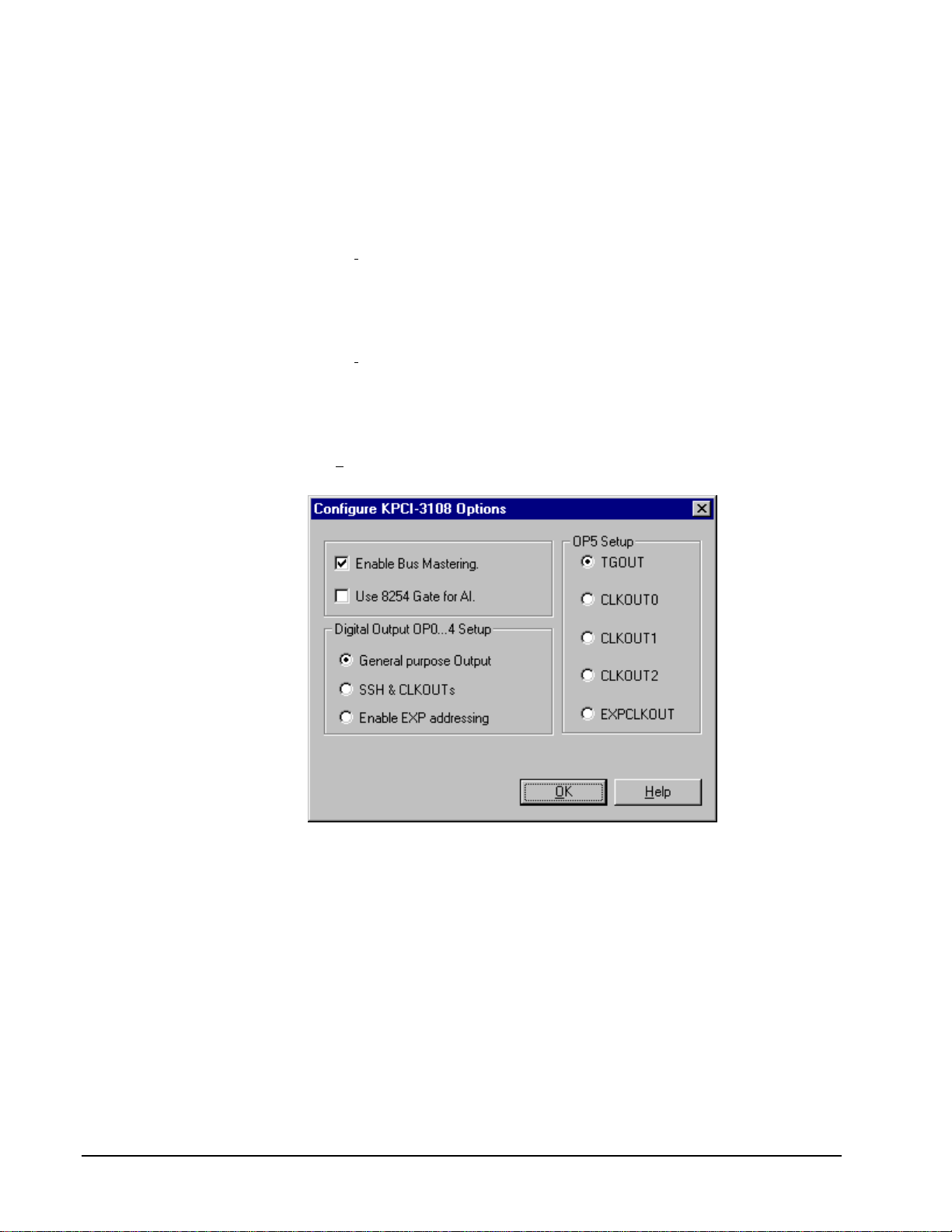
Special…
The Special… button displays the following dialog box of KPCI-3108 Series-specific
configuration options:
Enable Bus Mastering
Bus Mastering is a mode that PCI devices use to perform DMA data transfers. The
KPCI-3108 Series can use bus mastering on motherboards that support it. With bus
mastering disabled, the board will operate in interrupt mode when the Service
Request asks for DMA mode. For maximum throughput, enable bus mastering if your
motherboard supports it.
Motherboards compliant with revision 2.1 of the PCI specification support bus
mastering. Almost all newer motherboards support bus mastering but some require
BIOS settings to enable it for a particular PCI slot. Older motherboards may not
support bus mastering at all and may cause the system to hang, risking loss of
unwritten disk data and requiring you to reboot. Consult your computer
manufacturer’s documentation to determine if your motherboard supports bus
mastering.
16 • Configuring the KPCI-3108 Series Keithley KPCI-3108 Series
Page 17

To test bus-mastering, check the Enable Bus Mastering box, click OK as necessary to
exit the DriverLINX Configuration Panel and restart Windows. Close all other
applications, wait until all disk activity stops, and then run the DriverLINX AIO
Panel. If the AIO Panel can display an input signal then your motherboard is
compatible with your KPCI-3108 Series board. As long as your BIOS has enabled
bus mastering for the PCI slot your board is in, DriverLINX can use DMA mode.
Use 8254 Gate for AI
The KPCI-3108 Series supports analog input gating from two sources. The TGIN
signal directly controls the analog-to-digital converter and is programmable as active
high or low. Analog input is normally paced with the three-channel 8254
counter/timer chip. Two of the channels have an active high input available for
gating. For compatibility with other Keithley products, DriverLINX normally uses
the TGIN signa l when an applicatio n requests gating. However, you can configure
the device to use the counter/timer gate instead.
The two gate sources have the following features and advantages:
TGIN
• High or low level active
• Compatible with portable DriverLINX applications
C/T Gate
• High level active only
• TGIN pin is available for triggering with tasks that require both
triggering and gating
Digital Output OP0..4 Setup
The OP0 to OP4 pins output one of three groups of control or data signals.
DriverLINX does not automatically select a signal group but allows you to choose
which group the boa rd outputs through t hese connections.
Choose one the following groups of signals:
Group Signal Description Pin
General purpose I/O
GP0 Digital output data line OP0
GP1 Digital output data line OP1
GP2 Digital output data line OP2
GP3 Digital output data line OP3
GP4 Digital output data line OP4
Keithley KPCI-3108 Series Configuring the KPCI-3108 Series • 17
Page 18

Group Signal Description Pin
SSH control/Clock output
SSHO SSH control signal OP0
CLK0 Output of 8254 clock 0 (Logical Channel 1) OP1
CLK1 Output of 8254 clock 1 (Logical Channel 2) OP2
CLK2 Output of 8254 clock 2 (Logical Channels 0 and
3)
PCLK Emits a pulse for each analog input conversion OP4
Expansion accessory control
xA0 Expansion accessory address line OP0
xA1 Expansion accessory address line OP1
xA2 Expansion accessory address line OP2
xA3 Expansion accessory address line OP3
K Expansion accessory gain control OP4
OP3
Notes:
• It is important that you correctly configure digital channel 0 so that the
attached accessories or user hardware receive the intended signals.
• Any one of the clock signals is also available from the OP5 depending
on the Trigger/Clock Output Selection.
General purpose output
The General purpose output option enables writing 5-bits of digital data to the
OP0..4 pins. DriverLINX addresses these pins as Logical Channel 0 in the Digital
Output subsystem.
To enable the KPCI-3108’s 5-bit digital output, perform the following step in the
“Digital Output OP0..4 Setup” section of the Configure KPCI-3108 Options dialog
box:
1. Click the General purpose output option
Clock Output
To enable the KPCI-3108’s three 8254 counter outputs, perform the following step in
the “Digital Output OP0..4 Setup” section of the Configure KPCI-3108 Options
dialog box:
2. Click the SSH control & CLKOUTs option
Note: Any one of the clock signals is also available from the OP5 pin depending on
the OP5 Setup.
Expansion accessory control
You can expand the number of analog input channels connected to your KPCI-3108
Series board by using one or more expansion accessories. Each expansion accessory
18 • Configuring the KPCI-3108 Series Keithley KPCI-3108 Series
Page 19

is 1-to-16 multiplexer that replaces one onboard channel with sixteen expansion
channels. Configure your DriverLINX Logical Device to use the additional channels
by enabling the expansion accessory here.
To enable the KPCI-3108’s expansion accessory control signals and allow
applications to access expansion channels, perform the following steps:
1. In the “Digital Output OP0..4 Setup” section of the Configure KPCI-
3108 Options dialog box, click the Enable EXP addressing option
2. On the Analog Input Page, configure the subsystem for 16
single-ended channels
For information on programming a task to access expansion channels, see “Analog
Input Expansion Channels” on page 64.
OP5 Setup
The OP5 pin outputs one of se veral triggering and clock output signals. DriverLINX
does not automatically select an output signal but allows you to choose which signal
the board outputs through this connection.
Choose one of the following signals:
• TGOUT—Relays the TGIN signal when using external triggering or
gating, or is high during software-triggered analog input sampling
• CLK0—Output of 8254 clock 0 (Logical Channel 1)
• CLK1—Output of 8254 clock 1 (Logical Channel 2)
• CLK2—Output of 8254 clock 2 (Logical Channels 0 and 3)
• PCLK—Emits a pulse for each analog input conversion
Note: The clock signals are also available from the OP1 to OP3 pins when the
Digital Output OP0..4 Setup option is SSH control & CLKOUTs.
Keithley KPCI-3108 Series Configuring the KPCI-3108 Series • 19
Page 20

Analog Input Subsystem Page
Use the Analog Input subsystem page to choose between 16 single-ended or 8
differential analog input channels as a default configuration.
Channels
On the KPCI-3108 Series, each Analog Input channel can use single-ended or
differential termination modes. When configuring the Analog Input Subsystem, you
choose a default configuration for all channels. Applications can use the default
configuration or specify the termination mode for each channel that it uses. This
scheme supports applications that use KPCI-3108-specific features as well as those
that use only generic features. For applications that do specify the termination mode,
configure the subsystem for 16 channels.
For information on programming the termination mode, see “Analog Input Channels”
on page 58.
Range
The analog input ranges for the KPCI-3108 Series are fully software programmable.
DriverLINX grays out this property in the configuration dialog.
Interrupt
Windows automatically determines the interrupt level for the KPCI-3108 Series
board. DriverLINX disables this property.
DMA
The KPCI-3108 Series does not use DMA channels for direct memory transfers. PCI
devices use bus mastering for DMA. DriverLINX initially disables bus mastering for
your KPCI-3108 Series board. See “Special…” on page 16 for more information.
Calibrate
The KPCI-3108 Series supports semi-automatic calibration only. You can start the
calibration utility from the Windows Start menu. Additionally, applications can
request automatic zero-reference adjustments (offset calibration). For more
information, see “Analog Input Zero-Reference Adjustment” on page 63.
20 • Configuring the KPCI-3108 Series Keithley KPCI-3108 Series
Page 21

Analog Output Subsystem Page
Use the Analog Output subsystem page to set or view the initial output voltages.
Channels
Lists the analog output channels on the board and selects a channel for the Volts and
Initialize properties.
Range
The analog output ranges for the KPCI-3108 Series are fully software programmable.
DriverLINX grays out this property in the configuration dialog.
Volts
The Initialization Value property specifies the analog output value DriverLINX will
write to the selected Logical Channel upon hardware initialization. DriverLINX only
writes this value if you enable the In
itialize check box.
Interrupt
Windows automatically determines the interrupt level for the KPIC-3108 board.
DriverLINX disables this property.
DMA
The KPCI-3108 Series does not use DMA channels for direct memory transfers.
DriverLINX disables this property.
Initialize
Checking the Initialize check box instructs DriverLINX to use the Volts property for
to initialize the selected analog output channel.
Keithley KPCI-3108 Series Configuring the KPCI-3108 Series • 21
Page 22

Digital Input Subsystem Page
Use the Digital Input subsystem page to set configurable digital channels as input or
output.
Channels
The Channels proper ty allows you to select a Lo gical Channel for configuration or
viewing the channel’s range.
The KPCI-3108 Series supports both fixed and configurable digital channels.
DriverLINX defines the following Logical Channels for the KPCI-3108 Series
Digital Input Subsystem:
Logical Channel DriverLINX Function KPCI-3108 Series External
Connector
0 Standard Digital Input IP0 … IP5
1 Digital Input/Output Bit 0 … Bit 7
2 Digital Input/Output Bit 8 … Bit 15
3 Digital Input/Output Bit 16 … Bit 23
4 Digital Input/Output Bit 24 … Bit 31
5 External Clock XPCLK
6 External Trigger TGIN
Range
The Range property specifies the supported digital input range for the selected
Logical Channel. This is a read-only property.
Interrupt
Windows automatically determines the interrupt level for the KPIC-3108 board.
DriverLINX disables this property.
DMA
The KPCI-3108 Series does not use DMA channels for direct memory transfers.
DriverLINX disables this property.
22 • Configuring the KPCI-3108 Series Keithley KPCI-3108 Series
Page 23

Configuration Setup
The Configuration Setup property specifies the hardware configuration of the digital
I/O ports. Logical Channels 1 through 4 are configurable as i nput or output. Enter 1
to initially configure the selected channel as input or 0 to configure it as output.
Initialize
Checking the Initialize check box instructs DriverLINX to use the Configuration
S
etup property to configure the selected digital I/O channel.
Keithley KPCI-3108 Series Configuring the KPCI-3108 Series • 23
Page 24

Digital Output Subsystem Page
Use the Digital Output subsystem page to change the default digital output port
initialization values.
Channels
The Channels property allows you to select a Logical Channel for initialization or
viewing the channel’s range.
Logical Channel DriverLINX Function KPCI-3108 Series External
Connector
0 Standard Digital Output OP0 … OP4
1 Digital Input/Output Bit 0 … Bit 7
2 Digital Input/Output Bit 8 … Bit 15
3 Digital Input/Output Bit 16 … Bit 23
4 Digital Input/Output Bit 24 … Bit 31
Note: To use Logic al Channel 0, you configure pins OP0. .4 as General purpose
output on the Special… dialog.
Range
The Range property specifies the supported digital output range for the selected
Logical Channel. This is a read-only property.
Interrupt
Windows automatically determines the interrupt level for the KPIC-3108 board.
DriverLINX disables this property.
DMA
The KPCI-3108 Series does not use DMA channels for direct memory transfers.
DriverLINX disables this property.
24 • Configuring the KPCI-3108 Series Keithley KPCI-3108 Series
Page 25

Initialization Value
The Initialization Value property specifies the digital output value DriverLINX will
write to the selected Logical Channel upon hardware initialization. DriverLINX only
writes this value if you enable the In
itialize check box.
Initialize
Checking the Initialize check box instructs DriverLINX to use the Initialization
V
alue property for digital output port initialization.
Dec
This check box converts the Initialization Value property to decimal.
Hex
This check box converts the Initialization Value property to hexadecimal.
Keithley KPCI-3108 Series Configuring the KPCI-3108 Series • 25
Page 26

Counter/Timer Subsystem Page
Use the Counter/Timer subsystem page to set the default clock source frequency.
Resolution
The Resolution property specifies the default clock frequency of the master
oscillator. All models have a programmable 10 MHz, 5 MHz, 1 MHz or 100 kHz
clock source for pacing input/output tasks. This setting selects the default frequency.
Applications can use the default or specify a frequency for each task.
Interrupt
Windows automatically determines the interrupt level for the KPIC-3108 board.
DriverLINX disables this property.
26 • Configuring the KPCI-3108 Series Keithley KPCI-3108 Series
Page 27

Using the KPCI-3108 Series with
DriverLINX
Introduction
See the Analog I /O
Programming Guide for an
overview of DriverLINX
programming.
This chapter shows you how to set up and use KPCI-3108 Series hardware features
with DriverLINX.
The descriptions here use the Edit Service Request dialog for language and API
independence. For the corr ect syntax with the language you’re using, p lease see the
DriverLINX Technical Reference Manuals. For DriverLINX examples in your
programming language, p lease see the sourc e code examples in the subdirectories of
your DriverLINX installation directory or on the original distribution media.
KPCI-3108 Series Hardware Features
The KPCI-3108 Series offers your data-acquisition application a wide variety of
useful features. Analog inputs support mixed gains, termination modes and polarities,
as well as auto-zeroing, digital pre-, post- and about-triggering, and analog pre- and
about-triggering. Analog outputs are waveform-quality. The counter/timers are useraccessible. DriverLINX accesses these feats through its hardware independent
Applications Programming Interface (API).
The following table is a cross-reference between hardware features and the
DriverLINX features that access them.
Hardware Feature DriverLINX Feature
Calibration of each anal og input and output
range
Auto-zeroing of analog input channels Analog Input Zero-Reference Adjustment
Analog triggering Analog Stop Event (Pre- and About-
Digital triggering Digital Start Event (Post-Triggering)
DriverLINX provides a stand-alone KPCI-
3108 Calibration Utility.
Triggering)
Digital Stop Event (Pre- and AboutTriggering)
Page 28

Hardware Feature DriverLINX Feature
Programmable single-ended or differential
termination modes
Programmable gains Analog Input Channel Gains
Waveform-quality analog outputs Analog Output Subsystem
User-accessible counter/timers Counter/Timer Subsystem
Analog Input Channel Termination modes
Analog Output Channel Gains
DriverLINX Hardware Model for KPCI-3108 Series
DriverLINX provides a portable, hardware-independent API for data-acquisition
boards while still allowing applications to access unique or proprietary hardware
features of specific products. To achieve this goal, DriverLINX maps a hardwareindependent, or abstract, data-acquisition model onto KPCI-3108 Series hardware
capabilities.
The following sections describe how DriverLINX implements KPCI-3108 Series
hardware features as Subsystems, Modes, Operations, Events, Logical Channels,
Buffers, and Messages.
DriverLINX Subsystems
The KPCI-3108 Series supports the following DriverLINX subsystems:
1. Device—refers to a KPCI-3108 Series board as a whole.
2. Analog Input—refers to the analog input channels, clocks, and control
signals.
3. Analog Output—refers to the analog output channels, clocks, and
control signals.
4. Digital Input—refers to the digital input port as well as 1-bit digital
input (TTL) control signals, such as TGIN.
5. Digital Output—refers to the digital output port.
6. Counter/Timer—refers to the onboard counter/timer channels for
pacing analog input/output or performing measuring and waveform
generation funct ions.
DriverLINX Modes
Applications use modes in Service Requests to advise DriverLINX on their preferred
hardware data transfer technique. The DriverLINX modes fall into two general
classes:
• Foreground or synchronous modes. The calling application doesn’t
regain control until DriverLINX completes the Service Request.
DriverLINX supports this mode for simple, single value I/O operations
or software housekeeping functions that DriverLINX can complete
without a significant delay.
28 • Using the KPCI-3108 Series with DriverLINX Keithley KPCI-3108 Series
Page 29

• Background or asynchronous modes. The calling application regains
control as soon as DriverLINX initiates the task. The calling application
must synchronize with the data-acquisition task using status polling or
DriverLINX’s messages (preferred). DriverLINX supports this mode
for buffered data transfers or for commands that require a significant
time to complete.
DriverLINX supports four modes with the KPCI-3108 Series for its commands
(Service Requests).
• Polled Mode—This is a foreground or synchronous op eration.
DriverLINX supports this mode for simple, single-value I/O operations
that the data-acquisition board can complete without significant delay.
• Interrupt Mode—T his is a background or asynchronous op eration.
DriverLINX transfers data between the computer’s memory and the
data-acquisition board using hardware interrupts and programmed I/O
transfers.
• DMA Mode—This is a backgro und or asynchronous o peration.
DriverLINX programs the data-acquisition board to transfer data
between the computer’s memory and the board.
• Other Mode—This i s a foreground or synchronous operation.
DriverLINX supports this mode for initialization, configuration,
calibration, data conversion, and timebase operations.
Page 30

The following table summarizes the data acquisition modes that DriverLINX
supports for each subsystem with the Keithley KPCI-3108 Series.
Subsystem Polled Interrupt DMA Other
Analog Input ¥ ¥ ¥ ¥
Analog Output ¥ ¥ ¥ ¥
Digital Input ¥ ¥
Digital Output ¥ ¥
Counter/Timer ¥ ¥
Device
KPCI-3108 Series Supported DriverLINX Modes.
¥
¥
¥
¥
DriverLINX Operations and Events
Applications construct DriverLINX data-acquisition tasks by combining a small
number of DriverLINX operations and events in many possible ways. The following
table summarizes the operations and events that DriverLINX supports for the
Keithley KPCI-3108 Series. Later sections for each DriverLINX subsystem will
describe the operations and events in more detail.
Note: In addition to the operations shown in the table below, all subsystems allow
the MESSAGE operation in any Mode.
Subsystem Operation Events
Mode Timing Start Stop
Analog Input
Polled Start null null, cmd null, TC
Interrupt Start, Stop,
Status, Convert
DMA Start, Stop,
Status, Convert
Other Initialize
Analog Output
Polled Start null null, cmd null, TC
Interrupt Start, Stop,
Status, Convert
DMA Start, Stop,
Status, Convert
Other Initialize
Digital Input
Polled Start null null, cmd null, TC
Interrupt Start, Stop,
Status
Other Initialize,
Configure
dig, rate cmd, dig cmd, TC, dig
dig, rate cmd, dig cmd, TC, ana,
dig
rate cmd cmd, TC
rate cmd cmd, TC
rate cmd cmd, TC
DIO Setup
30 • Using the KPCI-3108 Series with DriverLINX Keithley KPCI-3108 Series
Page 31
Subsystem Operation Events
Mode Timing Start Stop
Digital Output
Polled Start null null, cmd null, TC
Interrupt Start, Stop,
Status
Other Initialize,
Configure
Counter/Timer
rate cmd cmd, TC
DIO Setup
Polled Start, Stop,
Status
Interrupt Start, Stop,
Status
Other Initialize,
Configure
Device
Other Initialize,
Capabilities
Allowed Operations and Events for KPCI-3108 Series Subsystems and Modes.
null, rate null, cmd null, TC
rate cmd cmd, TC
Page 32

The following list explains the Event abbreviations in the preceding table:
• null—Null or None Event specifies when a Service Request doesn’t
require an event
• cmd—Command Event specifies when DriverLINX starts or stops a
task on software command
• TC—Terminal Count Event specifies when DriverLINX processes all
data buffers once
• rate—Rate Event specifies how DriverLINX paces or clocks data
transfer
• dig—Digital Event specifies a trigger, clock, or other control signal to
pace, start, or stop a task
• ana—Analog Event specifies a trigger to start or stop a task
• DIO Setup—DIO Setup Event assigns a digital channel to either the
Digital Input or Digital Output Subsystem.
Logical Channels
DriverLINX designates the individually addressable hardware channels for each
subsystem as “Logical Channels.” Generally, the zero-based Logical Channel
numbering sequence closely follows the hardware manufacturer’s cha nnel numbering
scheme.
In some cases, however, DriverLINX assigns Logical Channel numbers to hardware
features that users don’t commonly think of as “channels.” For instance, DriverLINX
commonly models external hardware clock input lines, external hardware trigger
input lines, and external interrupt inputs as 1-bit digital Logical Channels. In other
cases, DriverLINX models subsystem-specific features, such as internal pacer clocks,
as members of a more general-purpose set of counter/timer channels.
For a list of DriverLINX assigned Logical Channel numbers, see the notes on each
supported subsystem.
Buffers
Applications usually use data buffers to exchange data between the application and
the data-acquisition hardware. When using data buffers, please note the following
points about DriverLINX’s data buffers:
• DriverLINX supports data-acquisition tasks with 1 to 255 data buffers
per task.
• DriverLINX imposes no size limits on a single buffer, although the
operating system or some hardware products may have size restrictions.
• User applications must allow DriverLINX to allocate all data buffers to
guarantee application portability to different hardware and operating
systems and to insure that the hardware can physically access the buffer
memory.
• User applications usually don’t have concurrent or immediate access to
the in-use data buffer while DriverLINX is executing a data-acquisition
task.
32 • Using the KPCI-3108 Series with DriverLINX Keithley KPCI-3108 Series
Page 33

Connecting Signals to the KPCI-3108 Series
Digital Start Event (Gating)
The Keithley hardware manual describes the data and control signals for the KPCI3108 Series and the connector pinouts for these signals. This section summarizes how
DriverLINX numbers the I/O data signals and how DriverLINX uses the control
connections for external clock, trigger, a nd gating inputs.
Analog Input Subsystem Signals
The Analog Input subsystem has 16 analog inputs and an analog ground. You set the
default subsystem configuration as 8 differential or 16 single-ended channels.
Applications can then use the default configuration or request a specific configuration
for each channel. See “Analog Input Channels” on page 58 for programming
information.
DriverLINX maps these connections to Logical Channels as shown in the following
table:
Physical Channels Connector Name Logical
0 – 7 Differential CH00 LO, HI – CH07 LO, HI 0 – 7
0 – 15 Single-ended CH00 HI – CH15 HI, AGND 0 – 15
How DriverLINX maps analog input hardware channels to Logical Channels.
Channels
Analog Input Pacing, Trigger ing and Gating Signals
Analog input tasks can use any of the Counter/Timer Logical Channels for pacing,
but uses Logical Channel 0 as the default. The clock sources can be internal or
external.
The Analog Input subsystem can use several control signals that DriverLINX defines
as external clocks, triggers and gates as shown in the following table:
Connector Name DriverLINX Usage
TGIN External trigger:
• Digital Start Event (Post-Triggering)
• Digital Stop Event (Pre- and About-
Triggering)
External gate:
• Rate Timing Event
•
XPCLK External pacer clock:
• Rate Generator: External Clocking
• Burst Generator: External Clocking
Page 34

Connector Name DriverLINX Usage
CLKIN0
CLKIN1
Divided external pacer clock:
• Divider-Rate G enerator: Exte rnal Clocking
• Divider-Burs t Generator: E xt ernal Clocking
GATEIN0
GATEIN1
How DriverLINX uses analog input control signals.
External gate:
• Rate Timing Event
34 • Using the KPCI-3108 Series with DriverLINX Keithley KPCI-3108 Series
Page 35

Analog Output Subsystem Signals
The Analog Output subsystem has 2 analog differential output connections.
DriverLINX maps these connections to Logical Channels as shown in the following
table:
Physical
Channel
0 DAC0 IN,DAC0 OUT 0
1 DAC1 IN, DAC1 OUT 1
How DriverLINX maps analog output hardware channels to Logical Channels.
Connector Name Logical
Channel
Analog Output Pacing, Triggering and Gating Signals
Analog output tasks can use any of the Counter/Timer Logical Channels for pacing,
but uses Logical Channel 1 as the default. The clock sources can be internal or
external.
The Analog Output subsystem can use several control signals that DriverLINX
defines as external clocks and gates as shown in the following table:
Connector Name DriverLINX Usage
XPCLK External pacer clock:
• Rate Generator: External Clocking
• Burst Generator: External Clocking
CLKIN0
CLKIN1
Divided external pacer clock:
• Divider-Rate G enerator: Exte rnal Clocking
• Divider-Burs t Generator: E xt ernal Clocking
GATEIN0
GATEIN1
How DriverLINX uses analog output control signals.
External gate:
• Rate Timing Event
Page 36

Digital Input Subsystem Signals
The Digital Input Subsystem has a 6-bit digital input port and a 32-bit digital
input/output port, as well as two control inputs which DriverLINX models as 1-bit
logical digital input ports. DriverLINX maps these signals to Logical Channels as
shown in the following table:
Logical Channel DriverLINX Function KPCI-3108 Series External
Connector
0 Standard Digital Input IP0 … IP5
1 Digital Input/Output Bit 0 … Bit 7
2 Digital Input/Output Bit 8 … Bit 15
3 Digital Input/Output Bit 16 … Bit 23
4 Digital Input/Output Bit 24 … Bit 31
5 External Clock XPCLK
6 External Trigger TGIN
How DriverLINX maps digital input hardware channels to Logical Channels.
Notes:
• If a channel is configured for output, reading it using the Digital Input
subsystem returns the last value written.
• The External Clock and External Trigger channels are not available for
reading but are available for clocking and triggering.
• Applications can assign a configurable channel to either subsystem
using a Configure operation. (See “Digital Channel Configuration” on
page 88.)
Digital Input Pacing, Triggering and Gating Signals
Digital input tasks can use any of the Counter/Timer Logical Channels for pacing, but
use Logical Channel 3 as the default. The clock sources can be internal or external.
The Digital Input subsystem can use several control signals that DriverLINX defines
as external clocks and gates as shown in the following table:
Connector Name DriverLINX Usage
CLKIN0
CLKIN1
GATEIN0
GATEIN1
How DriverLINX uses digital input control signals.
Divided external pacer clock:
• Divider-Rate G enerator: Exte rnal Clocking
External gate:
• Rate Timing Event
36 • Using the KPCI-3108 Series with DriverLINX Keithley KPCI-3108 Series
Page 37

Digital Output Subsystem Signals
The Digital Output subsystem has a 5-bit digital output port and a 32-bit digital
input/output port. DriverLINX maps these signals to Logical Channels as shown in
the following table:
Logical Channel DriverLINX Function KPCI-3108 Series External
Connector
0 Standard Digital Output OP0 … OP4
1 Digital Input/Output Bit 0 … Bit 7
2 Digital Input/Output Bit 8 … Bit 15
3 Digital Input/Output Bit 16 … Bit 23
4 Digital Input/Output Bit 24 … Bit 31
How DriverLINX maps digital output hardware channels to Logical Channels.
Notes:
• If a channel is configured for output, reading it (using the Digital Input
subsystem) returns the last value written.
• Applications can assign a configurable channel to either subsystem
using a Configure operation. (See “Digital Channel Configuration” on
page 88.)
• The board has an OP5 pin for any one of several clock outputs but not
for data out put. To select which clock signal the board outputs thr ough
OP5, see “Special…” on page 16.
Digital Output Pacing, Triggering and Gating Signals
Digital output tasks can use any of the Counter/Timer Logical Channels for pacing,
but use Logical Channel 2 as the default. The clock sources can be internal or
external.
The Digital Output subsystem can use several control signals that DriverLINX
defines as external clocks and gates as shown in the following table:
Connector Name DriverLINX Usage
CLKIN0
CLKIN1
GATEIN0
GATEIN1
How DriverLINX uses digital output control signals.
Divided external pacer clock:
• Divider-Rate G enerator: Exte rnal Clocking
External gate:
• Rate Timing Event
Counter/Timer Subsystem Signals
The Counter/Timer subsystem has a Logical Channel for each of the 8254 chip’s
three counter/timers. DriverLINX defines an additional Logical Channel for counters
1 and 2 in cascade mode.
Page 38

Analog I/O tasks can use the board’s external clock source (XPCLK) for pacing
instead of the output of an 8254 counter/timer. Also, analog input tasks can use the
board’s trigger/gate input (TGIN) for either triggering or gating.
DriverLINX maps these signals as shown in the following table:
Logical Channel 8254 Chip Counter Connector Name
0 Counters 1 & 2 XPCLK, TGIN, CLKIN1,
GATEIN1, CTOUT2
1 Counter 0 XPCLK, TGIN, CLKIN0,
GATEIN0, CTOUT0
2 Counter 1 XPCLK, TGIN, CLKIN1,
GATEIN1, CTOUT1
3 Counter 2 XPCLK, TGIN, CTOUT2
How DriverLINX maps counter/timer hardware channels to Logical Channels.
38 • Using the KPCI-3108 Series with DriverLINX Keithley KPCI-3108 Series
Page 39

Device Subsystem
f
The following sections describe how DriverLINX implements Device Subsystem
features for the KPCI-3108 Series.
Device Modes
The Device Subsystem supports only DriverLINX’s Other mode for all operations.
Device Operations
The KPCI-3108 Series Device Subsystem supports the following DriverLINX
operations:
If another application is using
the same data-acquisition
board, DriverLINX will
prevent Device Initialization
rom interfering with another
application’s data-acquisition
tasks.
• Initialize—DriverLINX aborts all data-acquisition tasks for every
subsystem controlled by the current application. DriverLINX then
initializes each subsystem.
• Capabilities—DriverLINX provides hardware-specific and
configuration information in the form of a Logical Device Descriptor
database. (If you are using the DriverLINX ActiveX controls, access
the Logical Device Descriptor with a DriverLINXLDD control rather
than with this operation.)
Page 40

Analog Input Subsystem
The following sections describe how DriverLINX implements Analog Input
Subsystem features for the KPCI-3108 Series.
Analog Input Modes
The Analog Input Subsystem supports the following modes:
• Polled—For single-value or single-scan analog input samples.
• Interrupt—For buffered transfers using programmed I/O.
• DMA—For buffered transfers using direct memory access.
• Other—For subsystem initialization and data conversion.
Analog Input Operations
The KPCI-3108 Series Analog Input Subsystem supports the following DriverLINX
operations:
• Initialize—aborts all active analog input data-acquisition tasks.
However, DriverLINX prevents one application from interfering with
another application’s data-acquisition tasks.
• Start—initiates a data-acquisition task using the Mode, Timing, Start,
and Stop Events, the Logical Channels, and the Buffers the application
specified in the Service Request.
• Status—reports the buffer position of the next sample that DriverLINX
will write into a buffer.
• Stop—terminates an analog input data-acquisition task.
• Message—DriverLINX displays a pop-up dialog box for the user
containing the text for the current DriverLINX error message.
Analog Input Pacing, Triggering and Gating
Options
The KPCI-3108 Series User’s Manual describes sever al pacing, triggering and gating
options available on KPCI-3108 Series models. The following table summarizes
these options and identifies which Service Request properties use them. Except as
indicated, all tasks must use Interrupt or DMA mode.
40 • Using the KPCI-3108 Series with DriverLINX Keithley KPCI-3108 Series
Page 41

Parameter Option Service Request Properties
Pacing Mode
Periodic (paced) Rate generator timing event
Burst Burst generator timing event
Clock Source
Software Single-value or single-scan
(Polled mode)
Internal Rate timing event with an internal clock
source
External +/- Rate timing event with an external clock
source
Burst Rate timing event in burst generator
mode with an internal or external clock
source
Trigger
Internal (software) Command start event
Command stop event
Terminal count stop event
Digital +/- Digital start event
Digital stop event
Analog Analog stop event
Trigger Mode
Post-trigger Digital start event
About-trigger Analog or Digital stop event with
positive delay
Pre-trigger Analog or Digital stop event with 0-
delay
Trigger-to-trigger Digital start event
Digital stop event
Trigger-to-about-trigger Digital start event
Digital stop event with positive delay
Gate
Level +/- Rate timing event
Digital start event (for use with a digital
timing event)
Page 42

Analog Input Timing Events
Timing Events specify how the hardware paces or clocks the acquisition of analog
input samples. DriverLINX uses the Timing Event to program when the KPCI-3108
Series acquires the next analog input sample.
The KPCI-3108 Series supports the following Timing Events:
• None—Sampling requires no pacing as DriverLINX is acquiring only a
single value or scan.
• Rate—The KPCI-3108 Series supports fixed rate and burst mode
sampling using internal and external clocks.
None or Null Timing Event
The Null Event specifies that the task does not need a clock to determine when to
acquire the next sample.
Rate Timing Event
The KPCI-3108 Series supports two types of Rate Events for analog input:
• Rate Generator—Generates a fixed rate clock with equal time
intervals between tics.
• Burst Generator—Generates a dual frequency clock with a fixed
number of tics at a high frequency separated by a time interval at a
lower frequenc y.
• Divider—Generates a fixed rate or dual frequency clock by dividing an
external input frequency.
KPCI-3108 Series boards have a programmable 10 MHz, 5 MHz, 1 MHz or 100 kHz
master clock frequency. The sample period can range from 10 µs to
a 100 kHz timebase. This means the sample rate can range from 0.000233 Hz to 100
kHz. However, using multiple channels or non-unity gains may reduce the maximum
sample rate that the hardware can accurately acquire. Consult your hardware manual
for details.
32
21
− tics with
42 • Using the KPCI-3108 Series with DriverLINX Keithley KPCI-3108 Series
Page 43

Rate Generator: Internal Clocking
property specifies the time interval between samples in tics.
An internally clocked Rate Generator produces a fixed rate clock with equal time
intervals between tics.
Period
Use an internally clocked rate generator when you want to acquire all analog input
samples at equally spaced time intervals.
How to set up the KPCI-3108 Series for fixed rate sampling using an internal clock.
For hardware independence,
specify the clock channel
using the symbolic constant,
DEFAULTTIMER, which
always maps to the default
Logical Channel for analog
input timing.
• Specify internal clocking using a Rate Generator on any available
Channel with any Internal Clock source. See “Counter/Timer
Subsystem” on page 110 for a description of clock sources.
• The Period
The minimum period is 10 µs.
• The Gate property specifies how the gate signal affects the operation of
the pacer clock. For analog input, DriverLINX uses the gate specified
in the device configuration. Valid settings for the TGIN gate are
Enabled, Disabled, NoConnect, High Level and Low Level. Valid
settings for the GATEIN0 or GATEIN1 gate are Enabled, Disabled,
NoConnect, and High Level. Valid settings, when pacing with channel
3, which has no external gate input, are Disabled and NoConnect. See
“Counter/Timer Subsystem” on page 110 for a description of each Gate
setting.
Note: When configured for the TGIN gate, the hardware does not
support using a gated clock with a digital start or stop trigger.
Page 44

• Example: For a programming example, see AIBUFFER in your
DrvLINX4\Source folder.
Rate Generator: External Clocki ng
An externally clocke d Rate Generator produces a rate clock with unknown time
intervals between tics.
Period (ext clk)
Use an externally clocked rate generator when you want to synchronize analog input
samples with a recurrent external signal. In this mode you will need a separate
external clock tic for each analog sample you want to acquire.
How to set up the KPCI-3108 Series for fixed rate sampling using an external clock.
For hardware independence,
specify the clock channel
using the symbolic constant,
DEFAULTTIMER, which
always maps to the default
Logical Channel for analog
input timing.
Be sure that the external
clock source is TTL
compatible, 0 V minimum to
+5 V maximum!
44 • Using the KPCI-3108 Series with DriverLINX Keithley KPCI-3108 Series
• Specify external clocking using a
Rate Generator on any available Channel with an External,
External+, or External- Clock source. See “Counter/Timer
Subsystem” on page 110 for a description of clock sources.
• Users should connect the external clock signal to the XPCLK line.
• The frequency of the external clock must not exceed 100 kHz.
• Specify a Period between the mi nimum and maximum external
clocking period. The value doesn’t affect the external clock frequency,
but DriverLINX requires a valid hardware value in case the application
requests a timebase operation and to optimize data transfer between the
driver and the application.
Page 45

• The Gate property specifies how the gate signal affects the operation of
the pacer clock. For analog input, DriverLINX uses the gate specified
in the device configuration. Valid settings for the TGIN gate are
Enabled, Disabled, NoConnect, High Level and Low Level. Valid
settings for the GATEIN0 or GATEIN1 gate are Enabled, Disabled,
NoConnect, and High Level. Valid settings, when pacing with channel
3, which has no external gate input, are Disabled and NoConnect. See
“Counter/Timer Subsystem” on page 110 for a description of each Gate
setting.
Note: When configured for the TGIN gate, the hardware does not
support using a gated clock with a digital start or stop trigger.
Page 46

Burst Generator: Internal Clocking
An internally clocked Burst Generator produces a dual frequency clock with a fixed
number of tics at a high frequency repeated at a lower frequency.
Use an internally clocked rate generator when you want to acquire analog input
samples from a several channels at closely spaced time intervals and then repeat at
longer intervals.
How to set up the KPCI-3108 Series for burst mode sampling using an internal clock.
For hardware independence,
specify the clock channel
using the symbolic constant,
DEFAULTTIMER, which
always maps to the default
Logical Channel for analog
input timing.
46 • Using the KPCI-3108 Series with DriverLINX Keithley KPCI-3108 Series
• Specify internal clocking using a Burst Generator on any available
Channel with any Internal Clock source. See “Counter/Timer
Subsystem” on page 110 for a description of clock sources.
• The Period property specifies the time interval between bursts in tics.
The minimum period is 10 µs.
• The On time property specifies the time interval between samples. It
must be in the range of 10µs to 255µs. Also Pulses × (On time +1
must be less than Period.
• The Gate property specifies how the gate signal affects the operation of
the pacer clock. For analog input, DriverLINX uses the gate specified
in the device configuration. Valid settings for the TGIN gate are
Enabled, Disabled, NoConnect, High Level and Low Level. Valid
settings for the GATEIN0 or GATEIN1 gate are Enabled, Disabled,
NoConnect, and High Level. Valid settings, when pacing with channel
3, which has no external gate input, are Disabled and NoConnect. See
“Counter/Timer Subsystem” on page 110 for a description of each Gate
setting.
µ
s)
Page 47

Note: When configured for the TGIN gate, the hardware does not
support using a gated clock with a digital start or stop trigger.
• The Pulses property specifies how many channels the board samples in
each Period. Pulses must equal the number of channels in the channel
list.
Example: For a programming example, see AIBURST in your DrvLINX4\Source
folder.
Burst Generator: External Clocking
An externally clocked Rate Generator produces a dual frequency clock with a fixed
number of tics at a high, internal frequency repeated at a lower, externally controlled
frequency.
Use an externally clocked burst generator when you want to synchronize a burst of
analog input samples with a recurrent external signal. In this mode you will need a
separate external clock tic for each burst of analog samples you want to acquire.
BE SURE that the external
clock source is TTL
compatible, 0 V minimum to
+5 V maximum!
How to set up the KPCI-3108 Series for burst mode sampling using an external clock.
• Specify external clocking using a Burst Generator on any available
Channel with an External, External+, or External- Clock source.
See “Counter/Timer Subsystem” on page 110 for a description of clock
sources.
• Users should connect the external clock signal to the XPCLK line.
• Specify a Period between the mi nimum and maximum external
clocking period. The value doesn’t affect the external clock frequency,
but DriverLINX requires a valid hardware value in case the application
Page 48

requests a timebase operation and to optimize data transfer between the
driver and the application.
• The On time property specifies the time interval between samples. It
must be within the range of 10µs to 255µs. Also, Pulses × (On time
µ
s) must be less than Period.
+1
• The frequency of the external clock must not exceed 100 kHz.
• The Gate property specifies how the gate signal affects the operation of
the pacer clock. For analog input, DriverLINX uses the gate specified
in the device configuration. Valid settings for the TGIN gate are
Enabled, Disabled, NoConnect, High Level and Low Level. Valid
settings for the GATEIN0 or GATEIN1 gate are Enabled, Disabled,
NoConnect, and High Level. Valid settings, when pacing with channel
3, which has no external gate input, are Disabled and NoConnect. See
“Counter/Timer Subsystem” on page 110 for a description of each Gate
setting.
Note: When configured for the TGIN gate, the hardware does not
support using a gated clock with a digital start or stop trigger.
• The Pulses property specifies how many channels the board samples in
each Period. Pulses must equal the number of channels in the channel
list.
48 • Using the KPCI-3108 Series with DriverLINX Keithley KPCI-3108 Series
Page 49

Divider-Rate Generator: External Clocking
A divided, ext ernally clocked Ra te Generator produces a rate clock with unknown
time intervals between tics.
Period (ext clk)
Use a divider-rate generator when you want to synchronize analog input samples with
a recurrent, higher frequency, external signal. In this mode you will need a specified
number of external clock tics for each analog sample you want to acquire.
How to set up the KPCI-3108 Series for rate sampling using a divided external clock.
Be sure that the external
clock source is TTL
compatible, 0 V minimum to
+5 V maximum!
• Specify external clocking using a Divider Generator on any available
Channel with an External, or External+ Clock source. See
“Counter/Timer Subsystem” on page 110 for a description of clock
sources.
• Users should connect the external clock signal to the CLKIN0 line for
the channel 1 or the CLKIN1 line for channels 0 and 2.
• Specify the divisor for the external frequency in the Period property.
The resulting pacing frequency must not exceed 100 kHz.
• The Gate property specifies how the gate signal affects the operation of
the pacer clock. For analog input, DriverLINX uses the gate specified
in the device configuration. Valid settings for the TGIN gate are
Enabled, Disabled, NoConnect, High Level and Low Level. Valid
settings for the GATEIN0 or GATEIN1 gate are Enabled, Disabled,
NoConnect, and High Level. Valid settings, when pacing with channel
3, which has no external gate input, are Disabled and NoConnect. See
“Counter/Timer Subsystem” on page 110 for a description of each Gate
setting.
Page 50
Note: When configured for the TGIN gate, the hardware does not
support using a gated clock with a digital start or stop trigger.
Divider-Burst Generator: External Clocking
A divided, externally clocked Burst Generator produces a dual frequency clock with
a fixed number of tics at a high, internal frequency repeated at a lower, externally
controlle d frequency.
Use a divider-burst generator when you want to synchronize a burst of analog input
samples with a recurrent, higher frequency, external signal. In this mode you will
need a specified number of external clock tics for each burst of analog samples you
want to acquire.
How to set up the KPCI-3108 Series for burst mode sampling using a divided external clock.
Note: The Edit Service Request dialog does not actually display all the properties for
a divider-burst generator. However, you can access all the properties
programmatically.
Be sure that the external
clock source is TTL
compatible, 0 V minimum to
+5 V maximum!
50 • Using the KPCI-3108 Series with DriverLINX Keithley KPCI-3108 Series
• Specify external clocking using a Divider Generator on any available
Channel with an External, or External+ Clock source. See
“Counter/Timer Subsystem” on page 110 for a description of clock
sources.
• Users should connect the external clock signal to the CLKIN0 line for
the channel 1 or the CLKIN1 line for channels 0 and 2.
• Specify the divisor for the external frequency in the Period property.
The resulting pacing frequency must not exceed 100 kHz.
Page 51

• The On time property specifies the time interval between samples. It
must be within the range of 10µs to 255µs. Also, Pulses × (On time
µ
s) must be less than Period.
+1
• The Gate property specifies how the gate signal affects the operation of
the pacer clock. For analog input, DriverLINX uses the gate specified
in the device configuration. Valid settings for the TGIN gate are
Enabled, Disabled, NoConnect, High Level and Low Level. Valid
settings for the GATEIN0 or GATEIN1 gate are Enabled, Disabled,
NoConnect, and High Level. Valid settings, when pacing with channel
3, which has no external gate input, are Disabled and NoConnect. See
“Counter/Timer Subsystem” on page 110 for a description of each Gate
setting.
Note: When configured for the TGIN gate, the hardware does not
support using a gated clock with a digital start or stop trigger.
• The Pulses property specifies how many channels the board samples in
each Period. Pulses must equal the number of channels in the channel
list.
Page 52

Analog Input Start Events
Start Events specify when the KPCI-3108 hardware starts acquiring analog input
data.
The KPCI-3108 Series supports the following Start Events:
• None—Use this event when the DriverLINX operation does not require
a Start Event.
• Command—DriverLINX starts the task on software command, i.e., as
soon as DriverLINX finishes programming the KPCI-3108 hardware
for the task.
• Digital—The hardware starts acquiring analog input samples when the
hardware detects the digital Logical Channel input satisfies the
condition specified in the Start Event.
None or Null Start Event
The Null Event specifies that the task does not need a Start Event to begin the task.
Command Start Event
The Command Event starts data acquisition as soon as DriverLINX has completed
programming the data-acquisition hardware with the task parameters.
Digital Start Event (Post-Triggering)
The KPCI-3108 can acquire analog input samples after the hardware detects a digital
trigger condition. Use post-triggering when you want to synchronize the start of data
acquisition with an external signal.
How to set up the KPCI-3108 Series for post-triggered analog input.
52 • Using the KPCI-3108 Series with DriverLINX Keithley KPCI-3108 Series
Page 53

Digital Start Events contain mask, pattern, and match fields. The mask is logically
ANDed with the digital input data on the Logical Channel and then compared with
the pattern for a match/mismatch.
• Specify the Channel as 6. For hardware-independence, you can specify
the hardware external trigger channel by the symbolic constant,
DI_EXTTRG.
• Users should connect the external trigger signal to the TGIN line.
• Specify the Mask property as 1, or Bit 0, to indicate that DriverLINX
should only compare a 1-bit digital input value against the Pattern
property.
• Specify the Match property as N
• Specify the Pattern property as 0 for a rising, or positive, edge trigger
(≠0) or 1 for a fal l ing, or negative, edge trigger (≠1).
• Specify the Delay property as 0. The KPCI-3108 does not support a
delay in sampling after the start trigger.
Notes:
• When configured for the TGIN gate, the hardware does not support
using a gated clock with a digital start or stop trigger.
• If both the start trigger and stop trigger are digital events, they must
have identical Pattern settings.
• The hardware does not support using a digital start trigger with an
analog stop trigger.
When the hardware detects the trigger, DriverLINX sends a StartEvent message (or
event). For more information on messages, see “Analog Input Messages” on page 68.
Example: For a programming example, see AIDIGTRG in your DrvLINX4\Source
folder.
ot equals.
Digital Start Event (Gating)
The KPCI-3108 can pause and resume acquiring analog input samples based on the
level of a digital input condition. Use a digital start event to set up gating when using
a digital timing event. To set up gating for a Rate timing event, see “Rate Timing
Event” on page 42.
Page 54

How to set up the KPCI-3108 Series for gated analog input.
Digital Start Events contain mask, pattern, and match fields. The mask selects which
bit in the Logical Channel to use as a gate input. The pattern selects whether the gate
is active, or enables data-acquisition, when the gate signal is high or low.
• Specify the Channel as 6. For hardware-independence, you can specify
the hardware external trigger channel by the symbolic constant,
DI_EXTTRG.
• Users should connect the external gating signal to the TGIN line.
• Specify the Mask property as 1, or Bit 0, to identify the gate input bit
of the Logical Channel.
• Specify the Match property as E
quals.
• Specify the Pattern property as 0 for a low-level active gate or 1 for a
high-level active gate.
• Specify the Delay property as 0. DriverLINX does not use a delay with
gating.
54 • Using the KPCI-3108 Series with DriverLINX Keithley KPCI-3108 Series
Page 55

Analog Input Stop Events
Stop Events specify when the hardware stops acquiring analog input data.
The KPCI-3108 Series supports the following Stop Events:
• None—Use this event when the DriverLINX operation doesn’t require
a Stop Event.
• Command—DriverLINX stops the task on software command, i.e.,
when the application issues a Service Request with a Stop operation.
• Terminal count—DriverLINX stops the task after the data-acquisition
hardware has filled all the data buffers once.
• Analog—The hardware stops acquiring analog input samples when the
hardware detects the analog Logical Channel input satisfies the
condition specified in the Start Event.
• Digital—The hardware stops acquiring analog input samples when the
hardware detects the digital Logical Channel input satisfies the
condition specified in the Stop Event.
None or Null Stop Event
The Null Event specifies that the task does not need a Stop Event to end the task.
Command Stop Event
The Command Event stops data acquisition when the user application changes the
Operation property in the Service Request to Stop and resubmits the Service Request
to DriverLINX.
In Stop-on-Command mode , DriverLINX continuously cycles through al l the data
buffers filling them with analog input data from the data-acquisition hardware.
Terminal Count Stop Event
The Terminal Count Event stops data acquisition after DriverLINX has filled all the
data buffers once with analog input data. Use Terminal Count when you want to
acquire a single scan or fixed amount of data.
Analog Stop Event (Pre- and About-Triggering)
The KPCI-3108 can acquire analog input samples until the hardware detects an
analog trigger condition. Use pre-triggering when you want to synchronize the end of
data-acquisition with an external signal. Use about-triggering when you want to delay
the end of data-acquisition a fixed number of samples after the trigger.
Page 56

How to set up the KPCI-3108 Series for pre-triggered analog input.
Analog Stop Events contain Channel, Gain, Polarity and Limit fields. The limits
determine the type of analog event (Level, Edge, Limit, or Band). For the KPCI-3108
Series, only edge and band types are allowed. The hardware supports band triggering
directly, while DriverLINX emulates edge triggering by programming the smallest
band that the hardware supports. As the board acquires samples, it compares data
from the specified Channel against the High and Low Limits. The Polarity determines
whether the trigger occurs on a rising o r falling signal. A rising trigger occurs when a
sample above the high limit follows a sample below the low limit. Similarly, a falling
trigger occurs when a sample below the low limit follows a sample above the high
limit.
• Specify the Mode as DMA. The KPCI-3108 Series supports analog
triggering only in DMA mode.
• Specify the Logical Channel from the analog input subsystem. For the
KPCI-3108 Series, the analog event channel must be in the channel list.
The channel can occur more than once in the channel list, but the board
monitors for the trigger condition only while sampling for the first
occurrence of the channel.
• Specify the Gain property for the analog event channel. Use the same
gain as in the channel list.
• Specify the Polarity (or Slope) property as Pos for a rising trigger or
Neg for a falling trigger.
• Specify the Limit properties in hardware A/D codes as follows:
Type High Limit Low Limit
Edge Threshold Threshold
Band Lower Threshold Upper Threshold
56 • Using the KPCI-3108 Series with DriverLINX Keithley KPCI-3108 Series
Page 57

Programming Tip: Use the DriverLINX Volts2Code method to
easily convert volts to hardware A/D codes for the threshold properties.
• Specify the Delay property as 0 for pre-triggering, or a positive number
of samples to obtain after the trigger for about-triggering. The Delay
value must be a multiple of the number of channels in the channel list.
• The hardware does not support using a digital start trigger with an
analog stop trigger.
When the hardware detects the trigger, DriverLINX sends a StopEvent message (or
event) that identifies the buffer location of the last sample. For more information on
messages, see “Analog Input Messages” on page 68.
Example: For a programming example, see AISTPTRG in your DrvLINX4\Source
folder.
Digital Stop Event (Pre- and About-Triggering)
The KPCI-3108 can acquire analog input samples until the hardware detects a digital
trigger condition. Use pre-triggering when you want to synchronize the end of data
acquisition with an external signal.
How to set up the KPCI-3108 Series for pre-triggered analog input.
Digital Stop Events contain mask, pattern, and match fields. The mask is logically
ANDed with the digital input data on the Logical Channel and then compared with
the pattern for a match/mismatch.
• Specify the Channel as 6. For hardware-independence, you can specify
the hardware external trigger channel by the symbolic constant,
DI_EXTTRG.
• Users should connect the external trigger signal to the TGIN line.
• Specify the Mask property as 1, or Bit 0, to indicate that DriverLINX
should only compare a 1-bit digital input value against the Pattern
property.
Page 58

• Specify the Match property as Not equals.
• Specify the Pattern property as 0 for a rising, or positive, edge trigger
(≠0) or 1 for a falling, or negative , edge trigger (≠1).
32
21
• Specify the Delay property as an integer from 0 to
3108 continues sampling until it obtains this number of samples after
the trigger. The number must be a multiple of the number of channels in
the channel list.
Notes:
• Note: When configured for the TGIN gate, the hardware does not
support using a gated clock with a digital start or stop trigger.
• If both the start trigger and stop trigger are digital events, they must
have identical Pattern settings.
When the hardware detects the trigger, DriverLINX sends a StopEvent message (or
event) that identifies the buffer location of the last sample. For more information on
messages, see “Analog Input Messages” on page 68.
Example: For a programming example, see AIDSTPTG in your DrvLINX4\Source
folder.
− . The KPCI-
Analog Input Channels
The KPCI-3108 Series models support a variety of channel gains with differential or
single-ended termination modes. The Logical Device configuration sets the default
termination mode for analog input channels. An application can request a particular
termination mode for each channel it uses. The channel gains are also application
selectable.
The KPCI-3108 Series allows applications to specify the analog channels using three
techniques:
• Start Channel—Acquire data from a single channel.
• Start/Stop Channel Range—Acquire data from a consecutive range of
channels.
• Channel List—Acquire data from a list of channels.
Single Channel Analog Input
In single channel mode, the KPCI-3108 Series acquires all data from one channel at
the specified gain.
58 • Using the KPCI-3108 Series with DriverLINX Keithley KPCI-3108 Series
Page 59
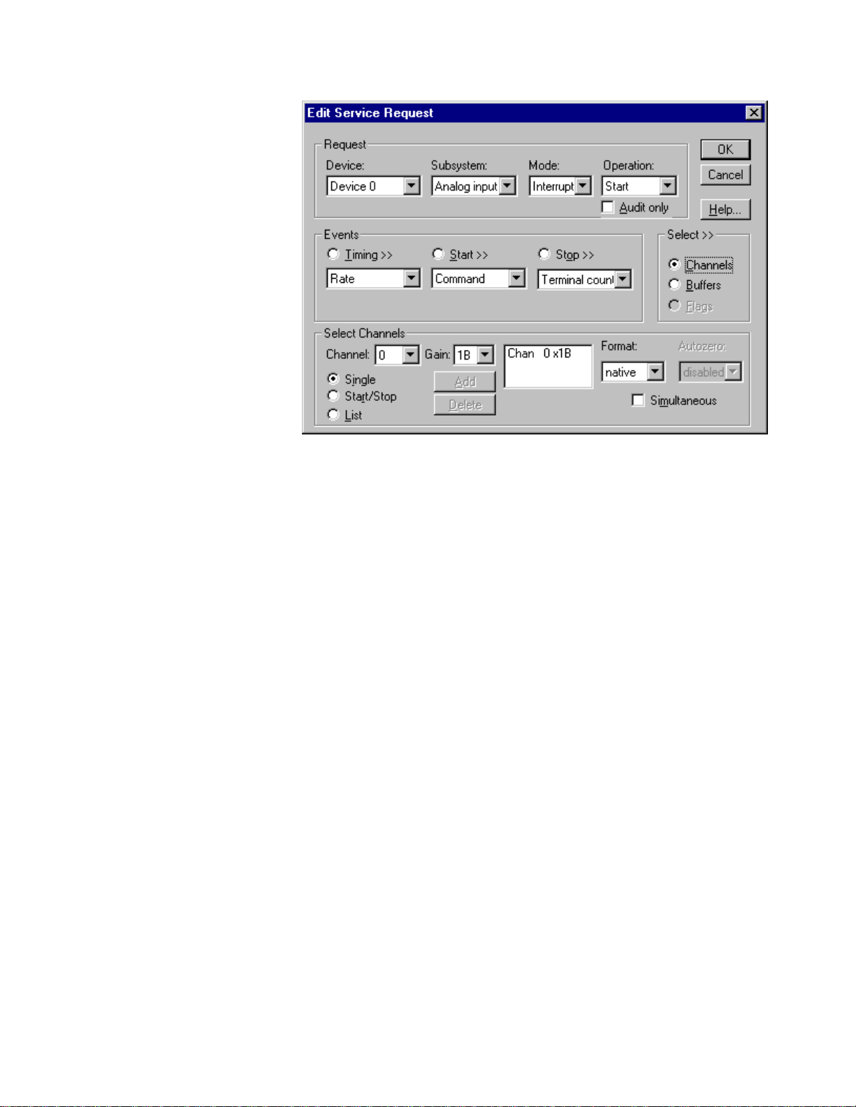
How to set up the KPCI-3108 Series for sampling on a single channel.
Multi-channel Analog Input Range
In multi-channel range mode, the KPCI-3108 Series acquires data from a consecutive
range of analog channels.
• The Start Channel’s gain only applies to the first channel.
• DriverLINX uses the Stop Channel’s gain for all the other analog
channels in the range.
• The gains may vary but they must all be either unipolar or bipolar.
• If the Start Channel is greater than the Stop Channel, the channel
sequence is [Start Channel,… Last Channel, 0,… Stop Channel], where
Last Channel is the highest numbered channel.
Page 60

How to set up the KPCI-3108 Series for sampling on a consecutive range of channels.
Multi-channel Analog Input List
In multi-channel list mode, the KPCI-3108 Series acquires data from an arbitrary list
of analog channels.
• The channel-gain list may contain up to 256 channels in any order. The
list may repeat the same channel with the same or different gains.
How to set up the KPCI-3108 Series to sample from an arbitrary list of channels.
60 • Using the KPCI-3108 Series with DriverLINX Keithley KPCI-3108 Series
Page 61

Analog Input Channel Gains
Each channel in a channel scan list has a gain code property to select the preamplifier gain when sampling that channel. The following tables show the
correspondence between the gain multiplier, the maximum input signal range, and the
gain code for each input range. Note: DriverLINX uses a negative (-) gain multiplier
to signify a bipolar (±) range.
You should be aware that using multiple channels or non-unity gains reduces the
maximum sample rate. Consult your hardware manual for details.
Gain Range Gain Code
-1 ±10 V 0
-2 ±5 V 1
-4 ±2.5 V 2
-8 ±1.25 V 3
-10 ±1 V 4
-20 ±500 mV 5
-40 ±250 mV 6
-80 ±125 mV 7
-100 ±100 mV 8
-200 ±50 V 9
-400 ±25 mV 10
-800 ±12.5 mV 11
1 0 - 10 V 16
2 0 - 5 V 17
4 0 - 2.5 V 18
8 0 - 1.25 V 19
10 0 - 1 V 20
20 0 - 500 mV 21
40 0 - 250 mV 22
80 0 - 125 mV 23
100 0 - 100 mV 24
200 0 - 50 V 25
400 0 - 25 mV 26
800 0 - 12.5 mV 27
Gains, Ranges, and Hardware Gain Codes for KPCI-3108 Series.
Use the DriverLINX Gain2Code method to easily convert between the gains in the
above tables and Gain Codes. Using this method makes applications portable to
different hardware models that have the same analog input ranges.
Expansion Channel Gains
The available gains for an expansion channel are the products of the expansion
board’s programmable (1 and 50) and the KPCI board’s programmable gains.
Page 62

If you are using an expansion accessory with other gain settings then you can scale
the data using DriverLINX’s conversion functions. For more information see
“Converting Entire Buffers” in the Analog I/O Programming Guide.
For information on configuring expansion accessories, see “Special…” on page 16.
For information on sampling from expansio n channels, “Analog Inp ut Expansion
Channels” on page 64.
Analog Input Channel Termination modes
On the KPCI-3108 Series, each Analog Input channel can use single-ended or
differential termination modes. When configuring the Analog Input Subsystem, you
choose a default configuration for all channels. Applications can use the default
configuration or specify the termination mode for each channel it uses. This scheme
supports applications that use KPCI-3108-specific features as well as those that use
only generic features.
Each channel in a channel list has a gain code property. To specify a termination
mode for a channel, an application includes a termination mode-type flag in its gain
code. The following table shows the flag value for each termination mode:
Termination mode Flag Value
Default Configuration CHAN_SEDIFF_DEFAULT = 0
Single-Ended
Differential
CHAN_SEDIFF_SE =
CHAN_SEDIFF_DIFF =
13
22×
13
23×
Note: The user chooses the default configuration on the Analog Input page of the
DriverLINX Configuration Panel. See “Analog Input Subsystem Page” on page 20.
For example, an application that requires or knows a channel’s termination mode
obtains the gain code for a single-ended channel with a bipolar gain of 4, with:
Gain2Code (-4) + CHAN_SEDIFF_SE
// This code will work with only drivers that allow
applications to specify a termination mode.
An application that does not require or know a channel’s termination mode obtains
the gain code for a channel with a bipolar gain of 4, with:
Gain2Code (-4)
// This code will work with any board that supports
bipolar ranges.
Analog Input Channel Coupling Modes
The KPCI-3108 Series an Analog Input channel with AC, DC or GND coupling.
When configuring t he Analog Input Subsystem, you choose a default configuration
for all channels. Applications can use the default configuration or specify the
coupling mode for each channel it uses. This scheme supports applications that use
KPCI-3108-specific features as well as those that use only generic features.
62 • Using the KPCI-3108 Series with DriverLINX Keithley KPCI-3108 Series
Page 63

Each channel in a channel list has a gain code property. To specify a coupling mode
for a channel, an application includes a coupling-mode flag in its gain code. The
following table shows the flag value for each coupling mode:
Coupling Mode Flag Value
Default Configuration CHAN_COUPLING_DEFAULT = 0
AC
DC
GND
CHAN_COUPLING_AC =
CHAN_COUPLING_DC =
CHAN_COUPLING_GND =
11
21×
11
22×
11
23×
Note: The user chooses the default configuration on the Analog Input page of the
DriverLINX Configuration Panel. See “Analog Input Subsystem Page” on page 20.
For example, an application that requires DC coupling for a for a channel with a
bipolar gain of 4, obtains the gain code by:
Gain2Code (-4) + CHAN_COUPLING_DC
// This code will work with only drivers that allow
applications to specify a coupling mode.
An application that does uses the configured coupling mode obtains the gain code for
a channel with a bipolar gain of 4, with:
Gain2Code (-4)
// This code will work with any board that supports
bipolar ranges.
Analog Input Zero-Reference Adjustment
Applications can request automatic zero-reference adjustments (offset calibration) by
selecting Enabled for Autozero property. Zero-reference adjustments ensure that
offset errors are minimized before starting the data-acquisition. Note, this takes
several seconds for each gain setting used in the service request.
Page 64

Analog Input Expansion Channels
Multiplexers can expand the number of analog input channels from the 16 base
channels up to 256 differential analog input channels. The KPCI-3108 Series
hardware automatically switches the multiplexer channels, allowing you to specify
expansion channels along with base channels in a channel list.
To enable DriverLINX to use multiplexers, enable expansion mode in the Configure
KPCI-3108 Options dialog (see “Special…” on page 16). With expansion mode
enabled, DriverLINX considers the board to have the original 16 base channels
followed by 256 expansion channels.
DriverLINX uses a static numbering scheme for attaching multiplexers. Attaching or
removing a mux from a base channel doesn’t cha nge the Logical Channel number of
any other channel. DriverLINX r eserves a fixed numbe r of expansion cha nnels for
each potential mux, whether it is attached or not.
To determine the DriverLINX Logical Channel number for a multiplexer channel,
use the following formula or refer to the table that follows it. Note that DriverLINX
uses 0-based numbering for all channels .
<logical chan#> = <num base chan> + <base chan#> × <num mux chan> + <mux chan#>
Term Description
<logical chan#> Logical Channel number to use in channel lists.
<num base chan> Number of base channels on the KPCI-3108 Series board
<base chan#> Base channel on the KPCI-3108 Series board where you attached
the mux.
<num mux chan> Number of expansion channels DriverLINX reserves for the mux.
(16 for KPCI-3108 expansion accessories).
<mux chan#> Channel on the expansion board where you attached the signal.
Mux channels are numbered from 0 to 15.
For example, the Logical Channel address for channel 4 on a mux attached to base
channel 3 is
16 + 3 × 16 + 4 = 68.
To specify multiplexer input channels 0, 1, and 2 on an expansion board connected to
base channel 0, use 16, 17, and 18 in the channel/gain list.
64 • Using the KPCI-3108 Series with DriverLINX Keithley KPCI-3108 Series
Page 65

Base Chan #
Mux
Chan #
10
11
0 1 2 3 4 5 6 7 etc
16 32 48 64 80 96 112 128
0
17 33 49 65 81 97 113 129
1
18 34 50 66 82 98 114 130
2
19 35 51 67 83 99 115 131
3
20 36 52 68 84 100 116 132
4
21 37 53 69 85 101 117 133
5
22 38 54 70 86 102 118 134
6
23 39 55 71 87 103 119 135
7
24 40 56 72 88 104 120 136
8
25 41 57 73 89 105 121 137
9
26 42 58 74 90 106 122 138
27 43 59 75 91 107 123 139
28 44 60 76 92 108 124 140
12
29 45 61 77 93 109 125 141
13
30 46 62 78 94 110 126 142
14
31 47 63 79 95 111 127 143
15
Table of logical channel numbers for KPCI-3108 expansion boards
Page 66
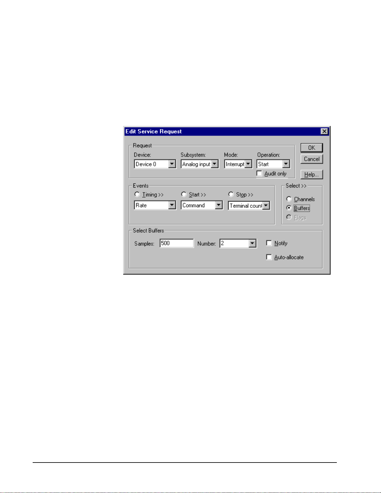
Analog Input Buffers
DriverLINX supports single-value, single-scan and buffered analog input.
• For single-value input, specify the Number of buffers as 0. The buffer
for a single value is the ioValue property.
• For single-scan input, specify the Number of buffers as 1 and the
number of Samples equal to the number of channels.
• For buffered input, specify the Number of buffers from 1 to 255 and
the number of Samples as desired.
For example, 500 samples/2
channels = 250 is ok, but 500
samples/3 channels = 166.67
is incorrect.
How to set up the KPCI-3108 Series to store samples in buffers.
Buffer Size
An individual DriverLINX buffer may have any size as long as the buffer length
holds an integral number of channel scans (i.e., a multiple of the number of analog
input channels you’re acquiring). This restriction enforces the requirement that all
acquired channels have the same number of sample s.
Buffer Usage
DriverLINX fills buffers sequentially until the task stops. During the task only
complete buffers are available to the application. Except for tasks that stop on
terminal count, the last buffer may be only partially full. If the task stops on a trigger,
use the StopEvent message (or event) to determine the location of the last sample.
For other cases, use a Status operation to determine the location of the last sample.
66 • Using the KPCI-3108 Series with DriverLINX Keithley KPCI-3108 Series
Page 67

Analog Input Data Coding
KPCI-3108 Series models return Analog Input 16-bit hardware codes in left-shifted
binary for unipolar ranges and l eft-justified two’s complement binary for bipolar
ranges. DriverLINX refers to these coding schemes as the “native” format.
For any programmable gain, the KPCI-3108 models return hardware codes with the
ranges in the following table:
Polarity Analog Input
Resolution
Unipolar 16 bits 0 to 65535
Bipolar 16 bits -32768 to 32767
Native Analog Input hardware codes for each KPCI-3108 Series polarity.
12
10
8
6
4
2
0
0 65535
6
4
2
0
-2
-4
-6
-32768 0 32767
Unipolar
Bipolar
Analog Input Hardware
Code
KPCI-3108 Series native Analog Input Codes versus Voltage Range for a ten-volt range.
DriverLINX refers to the default hardware analog-coding scheme as the “native”
format. For co mput er arithmetic in a higher level language, the 16-bit two’s
complement integer format is generally easier to use. Applications can use
DriverLINX’s data conversion operations to transform an entire data buffer from
many common integer and flo ating-point formats t o native format.
Page 68

Analog Input Messages
For analog input operations, DriverLINX can report the following messages to the
application:
DriverLINX
Explanation
Message
Service Start DriverLINX has started the acquisition task.
Service Done DriverLINX has completed the acquisition task.
Buffer Filled DriverLINX has filled an analog input buffer.
Start Event DriverLINX has processed t he interrupt for a hardware start
event.
Stop Event DriverLINX has processed the interrupt for a hardware stop
event.
Data Lost DriverLINX has detected an analog input data overrun
condition.
Critical Error DriverLINX has encountered an unexpected hardware or
software condition.
DriverLINX Event messages for analog input.
For detailed explanations of these messages see one of the following references:
• DriverLINX Technical Reference Manual for C/C++ users
• DriverLINX/VB Technical Reference Manual for VB or Delphi users
68 • Using the KPCI-3108 Series with DriverLINX Keithley KPCI-3108 Series
Page 69

Analog Output Subsystem
The following sections describe how DriverLINX implements Analog Output
Subsystem features for the KPCI-3108 Series.
Analog Output Modes
The Analog Output Subsystem supports the following modes:
• Polled—For single-value or single-scan analog output samples.
• Interrupt—For buffered transfers using programmed I/O.
• DMA—For buffered transfers using direct memory access.
• Other—For subsystem initialization and data conversion.
Analog Output Operations
The KPCI-3108 Series Analog Output Subsystem supports the following
DriverLINX operations:
• Initialize—aborts all active analog output data-acquisition tasks.
However, DriverLINX prevents one application from interfering with
another application’s data-acquisition tasks.
• Start—initiates a data-acquisition task using the Mode, Timing, Start,
and Stop Events, the Logical Channels, and the Buffers the application
specified in the Service Request.
• Status—reports the buffer position of the next sample that DriverLINX
will write from a buffer.
• Stop—terminates an analog output data-acquisition task.
• Message—DriverLINX displays a pop-up dialog box for the user
containing the text for the current DriverLINX error message.
Analog Output Pacing, Triggering and Gating
Options
The KPCI-3108 Series User’s Manuals describe several pacing, triggering and gating
options available on KPCI-3108 models. Most are available only on the KPCI3108AO models. The following table summarizes these options and identifies which
Service Request properties use them. Except as indicated all tasks must use Interrupt
or DMA mode.
Page 70

Parameter Option Service Request Properties
Pacing Mode
Periodic (paced) Rate generator timing event
Clock Source
Software Single-value or single-scan
(Polled mode)
Internal D/A clock Rate timing event with an internal clock
source
Internal A/D clock Rate timing event with an internal clock
source. A period of 0 signifies that the
A/D task operates the clock, which
controls both tasks
External +/- Rate timing event with an external clock
source
Trigger
Internal (software) Command start event
Command stop event
Terminal count stop event
Digital +/- Digital start event
Retrigger Digital start event (Interrupt mode; task
must meet certain conditions)
Gate
Level +/- Rate timing event
Digital start event (for use with a digital
timing event)
70 • Using the KPCI-3108 Series with DriverLINX Keithley KPCI-3108 Series
Page 71

Analog Output Timing Events
Timing Events specify how the hardware paces or clocks the writing of analog output
samples. DriverLINX uses the Timing Event to program when the KPCI-3108 Series
writes the next analog output sample.
The KPCI-3108 Series supports the following Timing Events:
• None—Task requires no pacing as DriverLINX is writing only a single
value or scan.
• Rate—The KPCI-3108 Series supports fixed rate writing using internal
and external clocks. You can also synchronize an Analog Output task
with an Analog Input task using a Rate Event.
None or Null Timing Event
The Null Event specifies that the task does not need a clock to determine when to
write the next sample.
Rate Timing Event
The KPCI-3108 Series supports two types of Rate Events for analog output:
• Rate Generator—Generates a fixed rate clock with equal time
intervals between tics.
• Burst Generator—Generates a dual frequency clock with a fixed
number of tics at a high frequency separated by a time interval at a
lower frequenc y.
• Divider—Generates a fixed rate or dual frequency clock by dividing an
external input frequency.
KPCI-3108 Series boards have a configurable 10 MHz, 5 MHz, 1 MHz or 100 kHz
master clock frequency. The sample period can range from 2µs to
means the sample rate can range from 0.000233 Hz to 500 kHz.
1232− tics. This
Page 72

Rate Generator: Internal Clocking
An internally clocked Rate Generator produces a fixed rate clock with equal time
intervals between tics.
Period
Use an internally clocked rate generator when you want to write analog output
samples at equally spaced time intervals.
How to set up the KPCI-3108 Series for fixed rate writing using an internal clock.
For hardware independence,
specify the clock channel
using the symbolic constant,
DEFAULTTIMER, which
always maps to the default
Logical Channel for analog
output timing.
Also see: “Synchronizing an Analog Output Task with an Analog Input Task” on
page 79.
Example: For a programming example, see AOBUFFER in your DrvLINX4\Source
folder.
72 • Using the KPCI-3108 Series with DriverLINX Keithley KPCI-3108 Series
• Specify internal clocking using a Rate Generator on any available
Channel with any Clock source. See “Counter/Timer Subsystem” on
page 110 for a description of clock sources.
• The Period property specifies the time interval between samples in tics.
The minimum period is 2 µs.
• The Gate property specifies how the gate signal affects the operation of
the pacer clock. Valid settings for the GATEIN0 or GATEIN1 gate are
Enabled, Disabled, NoConnect, and High Level. Valid settings, when
pacing with channel 3, which has no external gate input, are Disabled
and NoConnect. See “Counter/Timer Subsystem” on page 110 for a
description of each Gate setting.
Page 73

Rate Generator: External Clocki ng
An externally clocke d Rate Generator produces a rate clock with unknown time
intervals between tics.
Period (ext clk)
Use an externally clocked rate generator when you want to synchronize analog
output samples with a recurrent external signal. In this mode you will need a separate
external clock tic for each analog sample you want to write.
How to set up the KPCI-3108 Series for fixed rate writing using an external clock.
Be sure that the external
clock source is TTL
compatible, 0 V minimum to
+5 V maximum!
• Specify external clocking using a Rate Generator on Channel 1 with
an External, External+, or External- Clock source. See
“Counter/Timer Subsystem” on page 110 for a description of clock
sources.
• Users should connect the external clock signal to the XPCLK line.
• Specify a Period between the mi nimum and maximum external
clocking period. The value doesn’t affect the external clock frequency,
but DriverLINX requires a valid hardware value in case the application
requests a timebase operation and to optimize data transfer between the
driver and the application.
• The frequency of the external clock must not exceed 500 kHz.
• The Gate property specifies how the gate signal affects the operation of
the pacer clock. Valid settings for the GATEIN0 or GATEIN1 gate are
Enabled, Disabled, NoConnect, and High Level. Valid settings, when
pacing with channel 3, which has no external gate input, are Disabled
and NoConnect. See “Counter/Timer Subsystem” on page 110 for a
description of each Gate setting.
Page 74

Also see: “Synchronizing an Analog Output Task with an Analog Input Task” on
page 79.
74 • Using the KPCI-3108 Series with DriverLINX Keithley KPCI-3108 Series
Page 75
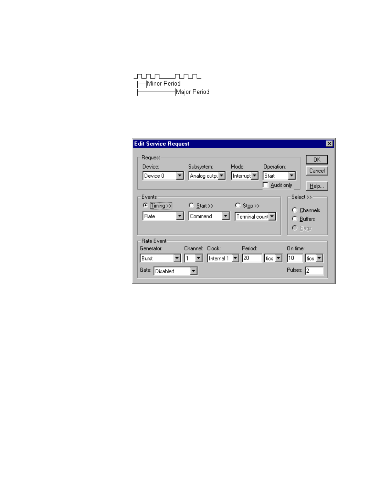
Burst Generator: Internal Clocking
An internally clocked Burst Generator produces a dual frequency clock with a fixed
number of tics at a high frequency repeated at a lower frequency.
Use an internally clocked rate generator when you want to acquire analog input
samples from a several channels at closely spaced time intervals and then repeat at
longer intervals.
For hardware independence,
specify the clock channel
using the symbolic constant,
DEFAULTTIMER, which
always maps to the default
Logical Channel for analog
input timing.
How to set up the KPCI-3108 Series for burst mode writing using an internal clock.
• Specify internal clocking using a Burst Generator on Channel 0 with
the Internal 1 Clock source. See “Counter/Timer Subsystem” on page
110 for a description of clock sources.
• The Period property specifies the time interval between bursts in tics.
The minimum period is 2 µs.
• The On time property specifies the time interval between samples. It
must be within the range of 2µs to 255µs. Also Pulses × (On time
µ
s) must be less than Period.
+1
• The Gate property specifies how the gate signal affects the operation of
the pacer clock. Valid settings for the GATEIN0 or GATEIN1 gate are
Enabled, Disabled, NoConnect, and High Level. Valid settings, when
pacing with channel 3, which has no external gate input, are Disabled
and NoConnect. See “Counter/Timer Subsystem” on page 110 for a
description of each Gate setting.
Page 76

• The Pulses property specifies how many channels the board samples in
each Period. Pulses must equal the number of channels in the channel
list.
Example: For a programming example, see AOBURST in your DrvLINX4\Source
folder.
Burst Generator: External Clocking
An externally clocked Rate Generator produces a dual frequency clock with a fixed
number of tics at a high, internal frequency repeated at a lower, externally controlled
frequency.
Use an externally clocked burst generator when you want to synchronize a burst of
analog input samples with a recurrent external signal. In this mode you will need a
separate external clock tic for each burst of analog samples you want to acquire.
How to set up the KPCI-3108 Series for burst mode writing using an external clock.
BE SURE that the external
clock source is TTL
compatible, 0 V minimum to
+5 V maximum!
76 • Using the KPCI-3108 Series with DriverLINX Keithley KPCI-3108 Series
• Specify external clocking using a Burst Generator on Channel 0 with
an External, External+, or External- Clock source. See
“Counter/Timer Subsystem” on page 110 for a description of clock
sources.
• Users should connect the external clock signal to the XPCLK line.
• Specify a Period between the mi nimum and maximum external
clocking period. The value doesn’t affect the external clock frequency,
but DriverLINX requires a valid hardware value in case the application
requests a timebase operation and to optimize data transfer between the
driver and the application.
Page 77
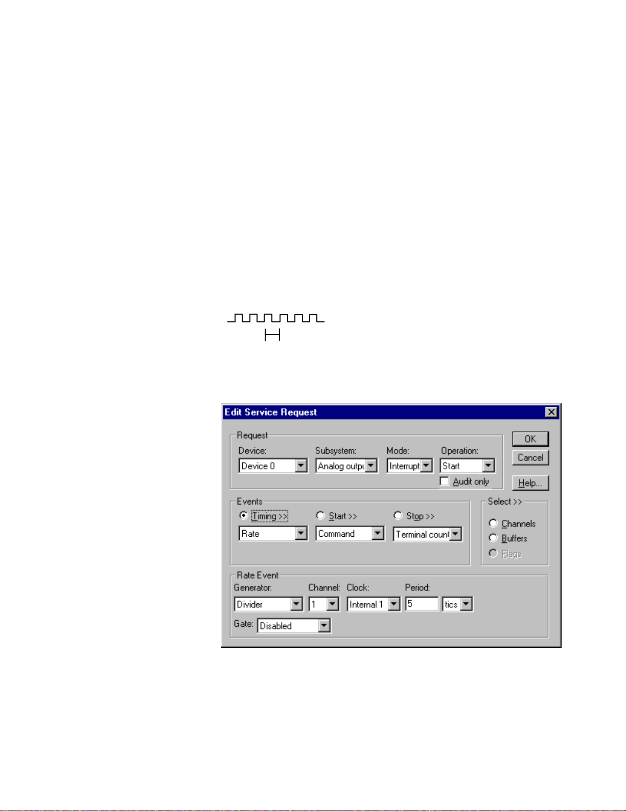
• The On time property specifies the time interval between samples. It
must be within the range of 2µs to 255µs. Also, Pulses × (On time
µ
s) must be less than Period.
+1
• The frequency of the external clock must not exceed 500 kHz.
• The Gate property specifies how the gate signal affects the operation of
the pacer clock. Valid settings for the GATEIN0 or GATEIN1 gate are
Enabled, Disabled, NoConnect, and High Level. Valid settings, when
pacing with channel 3, which has no external gate input, are Disabled
and NoConnect. See “Counter/Timer Subsystem” on page 110 for a
description of each Gate setting.
• The Pulses property specifies how many channels the board samples in
each Period. Pulses must equal the number of channels in the channel
list.
Divider-Rate Generator: External Clocking
A divided, ext ernally clocked Ra te Generator produces a rate clock with unknown
time intervals between tics.
Period (ext clk)
Use a divider-rate generator when you want to synchronize analog out put samples
with a recurrent, higher frequency, external signal. In this mode you will need a
specified number of external clock tics for each analog sample you want to output.
How to set up the KPCI-3108 Series for rate sampling using a divided external clock.
Page 78
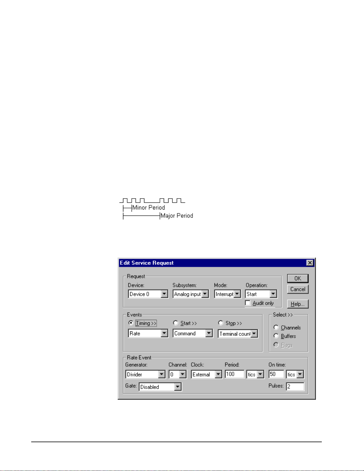
Be sure that the external
clock source is TTL
compatible, 0 V minimum to
+5 V maximum!
• Specify external clocking using a Divider Generator on any available
Channel with an External, or External+ Clock source. See
“Counter/Timer Subsystem” on page 110 for a description of clock
sources.
• Users should connect the external clock signal to the CLKIN0 line for
the channel 1 or the CLKIN1 line for channels 0 and 2.
• Specify the divisor for the external frequency in the Period property.
The resulting pacing frequency must not exceed 500 kHz.
• The Gate property specifies how the gate signal affects the operation of
the pacer clock. Valid settings for the GATEIN0 or GATEIN1 gate are
Enabled, Disabled, NoConnect, and High Level. Valid settings, when
pacing with channel 3, which has no external gate input, are Disabled
and NoConnect. See “Counter/Timer Subsystem” on page 110 for a
description of each Gate setting.
Divider-Burst Generator: External Clocking
A divided, externally clocked Burst Generator produces a dual frequency clock with
a fixed number of tics at a high, internal frequency repeated at a lower, externally
controlle d frequency.
Use a divider-burst generator when you want to synchronize a burst of analog output
samples with a recurrent, higher frequency, external signal. In this mode you will
need a specified number of external clock tics for each burst of analog samples you
want to write.
How to set up the KPCI-3108 Series for burst mode sampling using a divided external clock.
78 • Using the KPCI-3108 Series with DriverLINX Keithley KPCI-3108 Series
Page 79

Note: The Edit Service Request dialog does not actually display all the properties for
a divider-burst generator. However, you can access all the properties
programmatically.
Be sure that the external
clock source is TTL
compatible, 0 V minimum to
+5 V maximum!
• Specify external clocking using a Divider Generator on any available
Channel with an External, or External+ Clock source. See
“Counter/Timer Subsystem” on page 110 for a description of clock
sources.
• Users should connect the external clock signal to the CLKIN0 line for
the channel 1 or the CLKIN1 line for channels 0 and 2.
• Specify the divisor for the external frequency in the Period property.
The resulting pacing frequency must not exceed 500 kHz.
• The On time property specifies the time interval between samples. It
must be within the range of 2µs to 255µs. Also, Pulses × (On time
+1
µ
s) must be less than Period.
• The Gate property specifies how the gate signal affects the operation of
the pacer clock. Valid settings for the GATEIN0 or GATEIN1 gate are
Enabled, Disabled, NoConnect, and High Level. Valid settings, when
pacing with channel 3, which has no external gate input, are Disabled
and NoConnect. See “Counter/Timer Subsystem” on page 110 for a
description of each Gate setting.
• The Pulses property specifies how many channels the board samples in
each Period. Pulses must equal the number of channels in the channel
list.
Synchronizing an Analog Output Task with an Analog Input
Task
On the KPCI-3108 Series, DriverLINX can synchronize an analog output task with
an analog input task. The analog output task uses the same timing event as the input
task.
To synchronize an analog output (AO) task with an analog input (AI) task:
1. Set up the AI service request.
2. Set up the AO service request using an identical timing event as the AI
task, except with set the Period to zero. Both the AI and AO timing
event must use Counter/Timer channel 0.
3. Submit the AO service request. The hardware runs the AO task only
while the AI task is running.
4. Submit the AI service request to start both tasks.
Although both tasks shar e the same clock source , they are otherwise logically
independent of each other. Your application must manage and respond to each task
separately. If the AI task terminates before the AO task, the AO task will still be
logically active, but the clock stop sending timing pulses to the AO task until the next
AI task starts. If you want to terminate the AO task when the AI task stops, either set
up both service requests with equal buffer sizes and Stop Events, or issue a Stop
operation request for the AO task.
Page 80

Example: For a programming example, see AISYNCAO in your DrvLINX4\Source
folder.
80 • Using the KPCI-3108 Series with DriverLINX Keithley KPCI-3108 Series
Page 81

Analog Output Start Events
Start Events specify when the hardware starts acquiring analog output data.
The KPCI-3108 Series supports the following Start Events:
• None—Use this event when the DriverLINX operation does not require
a Start Event.
• Command—DriverLINX starts the task on software command, i.e., as
soon as DriverLINX finishes programming the KPCI-3108 hardware
for the task.
None or Null Start Event
The Null Event specifies that the task does not need a Start Event to begin the task.
Command Start Event
The Command Event starts data acquisition as soon as DriverLINX has completed
programming the data-acquisition hardware with the task parameters.
Analog Output Stop Events
Stop Events specify when the hardware stops acquiring analog output data.
The KPCI-3108 Series supports the following Stop Events:
• None—Use this event when the DriverLINX operation doesn’t require
a Stop Event.
• Command—DriverLINX stops the task on software command, i.e.,
when the application issues a Service Request with a Stop operation.
• Terminal count—DriverLINX stops the task after the data-acquisition
hardware has filled all the data buffers once.
None or Null Stop Event
The Null Event specifies that the task does not need a Stop Event to end the task.
Command Stop Event
The Command Event stops data acquisition when the user application changes the
Operation property in the Service Request to Stop and resubmits the Service Request
to DriverLINX.
In Stop-on-Command mode , DriverLINX continuously cycles through al l the data
buffers the analog output data to the data-acquisition hardware.
Terminal Count Stop Event
The Terminal Count Event stops data acquisition after DriverLINX has filled all the
data buffers once with analog output data. Use Terminal Count when you want to
write a single scan or fixed amount of data.
Page 82

Analog Output Channels
The KPCI-3108 Series allows applications to specify the analog channels using three
techniques:
• Start Channel—Write data to a single channel.
• Start/Stop Channel Range—Write data to a consecutive range of
channels.
• Channel List—Write data to a list of channels.
Single Channel Analog Output
In single channel mode, the KPCI-3108 Series writes all data to one channel at the
specified gain.
How to set up the KPCI-3108 Series for writing to a single channel.
Multi-channel Analog Output Range
In multi-channel range mode, the KPCI-3108 Series writes data to a consecutive
range of analog channels.
• The Start Channel’s gain only applies to the first channel.
• DriverLINX uses the Stop Channel’s gain for all the other analog
channels in the range.
• The Stop Channel must be greater than the Start Channel.
82 • Using the KPCI-3108 Series with DriverLINX Keithley KPCI-3108 Series
Page 83

How to set up the KPCI-3108 Series for writing to a consecutive range of channels.
Multi-channel Analog Output List
In multi-channel list mode, the KPCI-3108 Series writes data to an arbitrary list of
analog channels.
• For the KPCI-3108 Series, a channel cannot appear more than once in
the list.
How to set up the KPCI-3108 Series to write to an arbitrary list of channels.
Page 84

Analog Output Channel Gains
The KPCI-3108 Series models support a variety of channel gains. The following
table shows the correspondence between DriverLINX gains, the maximum output
signal range, and the gain code for each output range. Note: DriverLINX uses a
negative (-) gain value to signify a bipo lar (±) range.
AO Models
Gain Range Gain Code
-1 ±10 V 0
-2 ±5 V 1
1 0 to 10 V 2
2 0 to 5 V 3
Gains, Ranges, and Gain Codes for the KPCI-3108 Series.
Use the DriverLINX Gain2Code method to easily convert between the gains in the
above tables and hardware Gain Codes.
84 • Using the KPCI-3108 Series with DriverLINX Keithley KPCI-3108 Series
Page 85

Analog Output Buffers
DriverLINX supports single-value, single-scan and buffered analog output.
• For single-value output, specify the Number of buffers as 0. The
buffer for a single value is the ioValue property.
• For a single-scan output, specify the Number of buffers as 1 and the
number of Samples equal to the number of channels.
• For buffered output, specify the Number of buffers from 1 to 255 and
the number of Samples as desired.
For example, 500 samples/2
channels = 250 is ok, but 500
samples/3 channels = 166.67
is incorrect.
How to set up the KPCI-3108 Series to store samples in buffers.
Buffer Size
An individual DriverLINX buffer may have any size as long as the buffer length
holds an integral number of channel scans (i.e., a multiple of the number of analog
output channels you’re acquiring). This restriction enforces the requirement that all
acquired channels have the same number of sample s.
Buffer Usage
DriverLINX writes from buffers sequentially until the task stops. Except for tasks
that stop on terminal count, the last buffer may be only partially used. If the task
stops on a trigger, use the StopEvent message (or event) to determine the location of
the last sample. For other cases, use a Status operation to determine the location of
the last sample.
Analog Output Data Coding
KPCI-3108 Series uses the left-shifted, offset binary format to encode analog output
data, as shown in the following table. DriverLINX refers to this coding scheme as the
“native” format.
Page 86

Polarity Analog Output
Resolution
Analog Output
Hardware Code
Unipolar 16 bits 0 to 65535
Bipolar 16 bits -32768 to 32767
Native Analog Output hardware codes for the KPCI-3108 Series.
12
10
8
6
4
2
0
0 65535
Unipolar
6
4
2
0
-2
-4
-6
-32768 0 32767
Bipolar
KPCI-3108 Series native Analog Output Codes versus Voltage Range for a ten-volt range.
DriverLINX refers to the default hardware analog-coding scheme as the “native”
format. For co mput er arithmetic in a higher level language, the 16-bit two’s
complement integer format is generally easier to use. Applications can use
DriverLINX’s data conversion operations to transform an entire data buffer from
many common integer and flo ating-point formats t o native format.
86 • Using the KPCI-3108 Series with DriverLINX Keithley KPCI-3108 Series
Page 87

Analog Output Messages
For analog output operations, DriverLINX can report the following messages to the
application:
DriverLINX
Explanation
Message
Service Start DriverLINX has started the acquisition task.
Service Done DriverLINX has completed the acquisition task.
Buffer Filled DriverLINX has filled an analog output buffer.
Critical Error DriverLINX has encountered an unexpected hardware or
software condition.
DriverLINX Event messages for analog output.
For detailed explanations of these messages see one of the following references:
• DriverLINX Technical Reference Manual for C/C++ users
• DriverLINX/VB Technical Reference Manual for VB or Delphi users
Page 88

Digital Input Subsystem
The following sections describe how DriverLINX implements Digital Input
Subsystem features for the KPCI-3108 Series.
Digital Input Modes
The Digital Input Subsystem supports the following modes:
• Polled—For single-value or scan digital input samples.
• Interrupt—For buffered transfers using programmed I/O.
• Other—For subsystem initialization.
Digital Input Operations
The KPCI-3108 Series Digital Input Subsystem supports the following DriverLINX
operations:
• Initialize—aborts any active interrupt data-acquisition tasks and stops
the clock. DriverLINX prevents one application from interfering with
another application’s data-acquisition tasks.
• Configure—assigns a configurable digital channel to the input
subsystem.
• Start—initiates a data-acquisition task using the Mode, Timing, Start,
and Stop Events, the Logical Channels, and the Buffers the application
specified in the Service Request.
• Status—reports the buffer position of the next sample that DriverLINX
will write into a buffer.
• Stop—terminates a digital input data-acquisition task.
• Message—DriverLINX displays a pop-up dialog box for the user
containing the text for the current DriverLINX error message.
Digital Channel Configuration
The KPCI-3108 supports several configurable digital channels. To use them as inputs
you must first assign them to the Digital Input Subsystem using the “Configure
DriverLINX Device Dialog” (page 14) or by using a Configure operation. Only
channels 1 through 4 are configur able.
To configure a digital channel submit a service request with following settings:
• Subsystem—Digital Input or Digital Output
• Mode—Other
• Operation—Configure
• Timing Event—DIO Setup
• DIO Setup Channel — Channel number
• DIO Setup Mode—DIO BASIC
Example: For a programming example, see DIOCNFIG in your DrvLINX4\Source
folder.
88 • Using the KPCI-3108 Series with DriverLINX Keithley KPCI-3108 Series
Page 89

Digital Input Pacing, Tr i ggering and Gating
Options
The KPCI-3108 Series User’s Manuals describe several pacing, triggering and gating
options available for analog input on KPCI-3108 models. As DriverLINX uses the
analog input pacer clock for digital input, many of these options also apply to digital
input tasks. The following table summarizes these options and identifies which
Service Request properties use them. Except as indicated all tasks must use Interrupt
mode.
Parameter Option Service Request Properties
Pacing Mode
Periodic (paced) Rate generator timing event
Clock Source
Trigger
Software Single-value or single-scan
(Polled mode)
Internal Rate timing event with an internal clock
source
External + Rate timing event with an external clock
source in divider mode
Internal (software) Command start event
Command stop event
Terminal count stop event
Digital Input Timing Events
Timing Events specify how the hardware paces or clocks the reading of Digital Input
samples. DriverLINX uses the Timing Event to program when the KPCI-3108 Series
reads the next digital input sample from the port.
The KPCI-3108 Series supports the following Timing Events:
• None—Input requires no pacing as DriverLINX is reading only a single
value.
• Rate—The KPCI-3108 Series supports fixed rate sampling using
internal and external clocks.
None or Null Timing Event
The Null Event specifies that the task does not need a clock to determine when to
read the next sample.
Rate Timing Event
The KPCI-3108 Series supports only the Rate Generator mode for Rate Events for
digital input:
Page 90

• Rate Generator—Generates a fixed rate clock with equal time
intervals between tics.
• Divider—Generates a fixed rate clock by dividing an external input
frequency.
KPCI-3108 Series boards have a configurable 10 MHz, 5 MHz, 1 MHz or 100 kHz
master clock frequency. The sample period can range from 100µs to
1232− tics.
This means the sample rate can range from 0.000233 Hz to 10 kHz.
90 • Using the KPCI-3108 Series with DriverLINX Keithley KPCI-3108 Series
Page 91
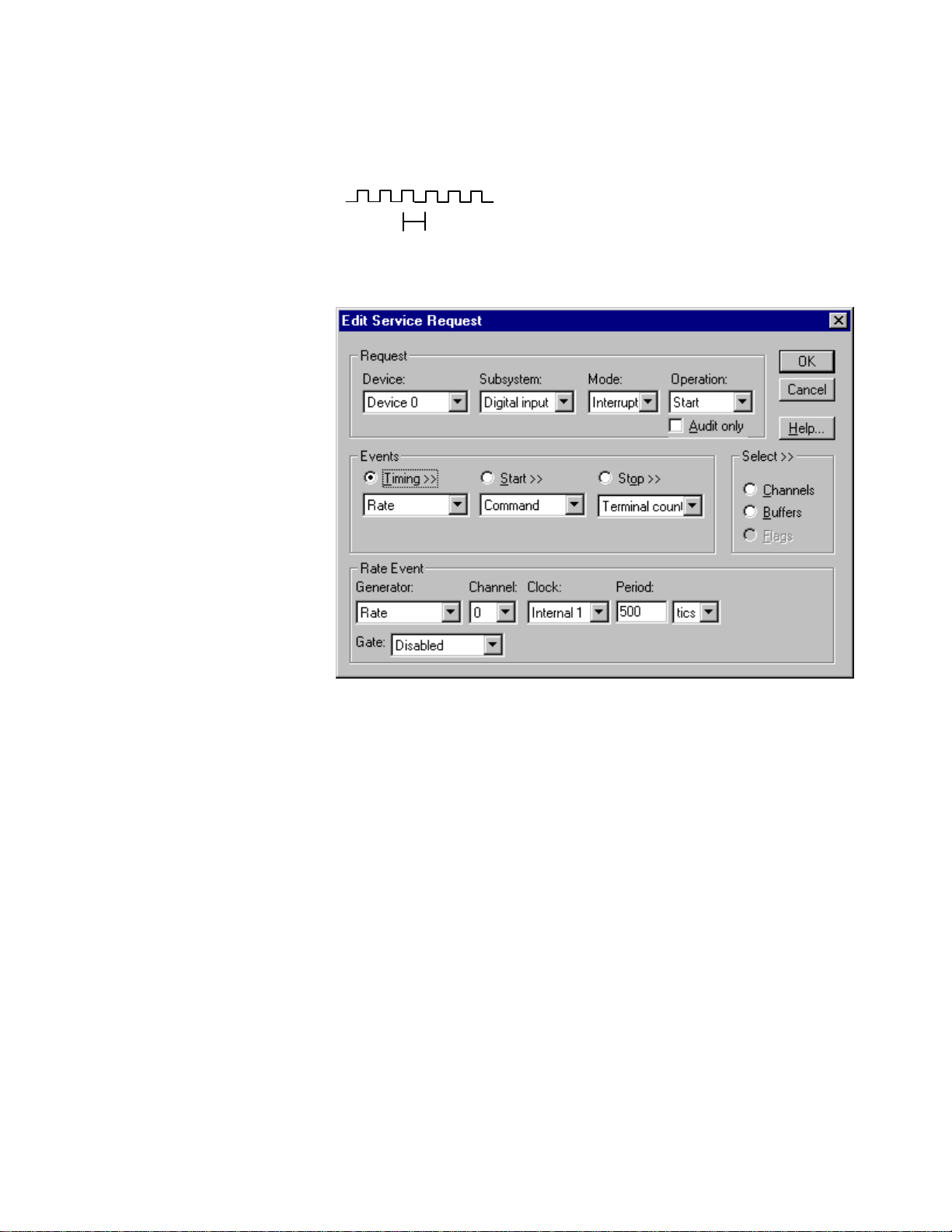
Rate Generator: Internal Clocking
property specifies the time interval between samples in tics.
An internally clocked Rate Generator produces a fixed rate clock with equal time
intervals between tics.
Period
Use an internally clocked rate generator when you want to acquire all digital input
samples at equally spaced time intervals.
How to set up the KPCI-3108 Series for fixed rate sampling using an internal clock.
For hardware independence,
specify the clock channel
using the symbolic constant,
DEFAULTTIMER, which
always maps to the default
Logical Channel for digital
output timing.
• Specify internal clocking using a Rate Generator on any Channel with
any valid Clock source. See “Counter/Timer Subsystem” on page 110
for a description of clock sources.
• The Period
The minimum period is 100 µs.
• The Gate property specifies how the gate signal affects the operation of
the pacer clock. Valid settings for the GATEIN0 or GATEIN1 gate are
Enabled, Disabled, NoConnect, and High Level. Valid settings, when
pacing with channel 3, which has no external gate input, are Disabled
and NoConnect. See “Counter/Timer Subsystem” on page 110 for a
description of each Gate setting.
Example: For a programming example, see DIBUFFER in your DrvLINX4\Source
folder.
Page 92

Divider-Rate Generator: External Clocking
A divided, ext ernally clocked Ra te Generator produces a r ate clock with unknown
time intervals between tics.
Period (ext clk)
Use a divider-rate generator when you want to synchronize digital input samples with
a recurrent, higher frequency, external signal. In this mode you will need a specified
number of external clock tics for each digital sample you want to acquire.
How to set up the KPCI-3108 Series for rate sampling using a divided external clock.
Be sure that the external
clock source is TTL
compatible, 0 V minimum to
+5 V maximum!
92 • Using the KPCI-3108 Series with DriverLINX Keithley KPCI-3108 Series
• Specify external clocking using a Divider Generator on any available
Channel with an External, or External+ Clock source. See
“Counter/Timer Subsystem” on page 110 for a description of clock
sources.
• Users should connect the external clock signal to the CLKIN0 line for
the channel 1 or the CLKIN1 line for channels 0 and 2.
• Specify the divisor for the external frequency in the Period property.
The resulting pacing frequency must not exceed 10 kHz.
• The Gate property specifies how the gate signal affects the operation of
the pacer clock. Valid settings for the GATEIN0 or GATEIN1 gate are
Enabled, Disabled, NoConnect, and High Level. Valid settings, when
pacing with channel 3, which has no external gate input, are Disabled
and NoConnect. See “Counter/Timer Subsystem” on page 110 for a
description of each Gate setting.
Page 93

Digital Input Start Events
Start Events specify when the KPCI-3108 Series hardware starts reading digital input
data.
The KPCI-3108 Series supports the following Start Events for digital input:
• None—Use this event when the DriverLINX operation doesn’t require
a Start Event.
• Command—DriverLINX starts the task on software command, i.e., as
soon as DriverLINX finishes programming the KPCI-3108 hardware
for the task.
None or Null Start Event
The Null Event specifies that the task does not need a Start Event to begin the task.
Command Start Event
The Command Event starts data acquisition as soon as DriverLINX has completed
programming the KPCI-3108 Series hardware with the task parameters.
Digital Input Stop Events
Stop Events specify when the KPCI-3108 Series hardware stops reading digital input
data.
The KPCI-3108 Series supports the following Stop Events for digital input:
• None—Use this event when the DriverLINX operation doesn’t require
a Stop Event.
• Command—DriverLINX stops the task on software command, i.e.,
when the application issues a Service Request with a Stop operation.
• Terminal count—DriverLINX stops the task after the KPCI-3108
Series hardware has filled all the data buffers once.
None or Null Stop Event
The Null Event specifies that the task does not need a Stop Event to end the task.
Command Stop Event
The Command Event stops data acquisition when the user application changes the
Operation property in the Service Request to Stop and resubmits the Service Request
to DriverLINX.
In Stop-on-Command mode , DriverLINX continuously cycles through al l the data
buffers, reading from the digital port on the KPCI-3108 Series.
Terminal Count Stop Event
The Terminal Count Event stops data acquisition after DriverLINX has read the
digital input data into all the data buffers once. Use terminal count when you want to
read a fixed amount of data.
Page 94

Digital Input Channels
The KPCI-3108 Series allows applications to specify the digital channels using three
techniques:
• Start Channel—Acquire data from a single channel.
• Start/Stop Channel Range—Acquire data from a consecutive range of
channels.
• Channel List—Acquire data from a list of channels.
Digital Input Logical Channels
The KPCI-3108 Series supports both fixed and configurable digital channels.
DriverLINX defines the following Logical Channels for the KPCI-3108 Series
Digital Input Subsystem:
Logical Channel DriverLINX Function KPCI-3108 Series External
Connector
0 Standard Digital Input IP0 … IP5
1 Digital Input/Output Bit 0 … Bit 7
2 Digital Input/Output Bit 8 … Bit 15
3 Digital Input/Output Bit 16 … Bit 23
4 Digital Input/Output Bit 24 … Bit 31
5 External Clock XPCLK
6 External Trigger TGIN
94 • Using the KPCI-3108 Series with DriverLINX Keithley KPCI-3108 Series
Page 95
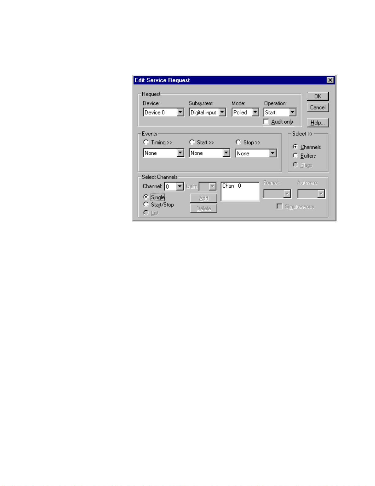
Single Channel Digital Input
In single channel mode, the KPCI-3108 Series acquires all data from one channel.
How to set up the KPCI-3108 Series for sampling on a single channel.
Multi-channel Digital Input Range
In multi-channel range mode, the KPCI-3108 Series acquires all data from a
consecutive range of digital channels.
• The Stop Channel must be greater than the Start Channel.
Page 96

How to set up the KPCI-3108 Series for sampling on a consecutive range of channels.
Multi-channel Digital Input List
In multi-channel list mode, the KPCI-3108 Series acquires all data from an arbitrary
list of digital channels.
How to set up the KPCI-3108 Series to sample from an arbitrary list of channels.
96 • Using the KPCI-3108 Series with DriverLINX Keithley KPCI-3108 Series
Page 97

Digital Input Buffers
DriverLINX supports single-value, single-scan and buffered digital input.
• For single-value input, specify the Number of buffers as 0. The buffer
for a single value is the ioValue property.
• For single-scan input, specify the Number of buffers as 1 and the
number of Samples equal to the number of channels.
• For buffered input, specify the Number of buffers from 1 to 255 and
the number of Samples as desired.
How to set up the KPCI-3108 Series to read digital samples using data buffers.
Buffer Usage
DriverLINX fills buffers sequentially until the task stops. During the task only
complete buffers are available to the application. Except for tasks that stop on
terminal count, the last buffer may be only partially full. Use a Status operation to
determine the location of the last sample.
Page 98

Digital Input Messages
For digital input operations, DriverLINX can report the following messages to the
application:
DriverLINX
Explanation
Message
Service Start DriverLINX has started the acquisition task.
Service Done DriverLINX has completed the acquisition task.
Buffer Filled DriverLINX has filled a digital input buffer.
Critical Error DriverLINX has encountered an unexpected hardware or
software condition.
DriverLINX Event messages for digital input.
For detailed explanations of these messages see one of the following references:
• DriverLINX Technical Reference Manual for C/C++ users
• DriverLINX/VB Technical Reference Manual for VB or Delphi users
98 • Using the KPCI-3108 Series with DriverLINX Keithley KPCI-3108 Series
Page 99

Digital Output Subsystem
The following sections describe how DriverLINX implements Digital Output
Subsystem features for the KPCI-3108 Series.
Digital Output Modes
The Digital Output Subsystem supports the following modes:
• Polled—For single-value digital output samples.
• Interrupt—For buffered transfers using programmed I/O.
• Other—For subsystem initialization.
Digital Output Operations
The KPCI-3108 Series Digital Output Subsystem supports the following DriverLINX
operations:
• Initialize—aborts any active interrupt data-acquisition tasks and stops
the clock. DriverLINX prevents one application from interfering with
another application’s data-acquisition tasks.
• Start—initiates a data-acquisition task using the Mode, Timing, Start,
and Stop Events, the Logical Channels, and the Buffers the application
specified in the Service Request.
• Status—reports the buffer position of the next sample that DriverLINX
will write from a buffer.
• Stop—terminates a digital output data-acquisition task.
• Message—DriverLINX displays a pop-up dialog box for the user
containing the text for the current DriverLINX error message.
Digital Output Initialization
By default, the Digital Output subsystem writes zero into the digital output port. You
can specify a different initial output value using the Configure DriverLINX Device
dialog. See “Digital Output Subsystem Page” on page 24.
Digital Channel Configuration
The KPCI-3108 supports several configurable digital channels. To use them as
outputs you must first assign them to the Digital Output Subsystem using the
“Configure DriverLINX Device Dialog” (page 14) or by using a Configure operation.
See “Digital Channel Configuration” on page 88 for more information on the
configure op eration.
Page 100

Digital Output Pacing, Triggering and Gating
Options
The KPCI-3108 Series User’s Manuals describe several pacing, triggering and gating
options available for analog input on KPCI-3108 models. As DriverLINX uses the
analog input pacer clock for digital output, many of these options also apply to digital
output tasks. The following table summarizes these options and identifies which
Service Request properties use them. Except as indicated all tasks must use Interrupt
mode.
Parameter Option Service Request Properties
Pacing Mode
Periodic (paced) Rate generator timing event
Clock Source
Trigger
Software Single-value or single-scan
(Polled mode)
Internal Rate timing event with an internal clock
source
External + Rate timing event with an external clock
source in divider mode
Internal (software) Command start event
Command stop event
Terminal count stop event
Digital Output Timing Events
Timing Events specify how the hardware paces or clocks writing Digital Output
samples. DriverLINX uses the Timing Event to program when the KPCI-3108 Series
writes the next digital output sample from the port.
The KPCI-3108 Series supports the following Timing Events:
• None—Output requires no pacing as DriverLINX is writing only a
single value.
• Rate—The KPCI-3108 Series supports fixed rate writing using internal
and external clocks.
None or Null Timing Event
The Null Event specifies that the task does not need a clock to determine when to
write the next sample.
Rate Timing Event
The KPCI-3108 Series supports only the Rate Generator mode for Rate Events for
digital output:
100 • Using the KPCI-3108 Series with DriverLINX Keithley KPCI-3108 Series
 Loading...