

Tektronix Using Keithley DriverLINX with KPCI-3101/2/3/4 or KPCI-3110/16 (1.3MB) User manual
Page 1

Keithley KPCI-3100 Series
Using DriverLINX with Your
Hardware
Page 2

Information in this document is subject to change without notice. T he soft ware
described is this document is furnished under a license agreement. The software may
be used or copied only in accordance with the terms of the agreement.
SCIENTIFIC SOFTWARE TOOLS, INC. SHALL NOT BE LIABLE FOR ANY
SPECIAL, INCIDENTAL, OR CONSEQUENTIAL DAMAGES RELATED TO
THE USE OF THIS PRODUCT. THIS PRODUCT IS NOT DESIGNED WITH
COMPONENTS OF A LEVEL OF RELIABILITY SUITABLE FOR USE IN LIFE
SUPPORT OR CRITICAL AP PLICATIONS.
This document may not, in whole or in part, be copied, photocopied, reproduced,
translated or reduced to any electronic medium or machine readable form without
prior written consent from Scientific Software Tools, Inc.
Keithley KPCI-3100 Series: Using DriverLINX with Your Hardware
Copyright 1999-2001 by Scientific Software Tools, Inc.
All rights reserved.
SST 28-0110-1
DriverLINX, SSTNET, and LabOBJX are registered trademarks and
DriverLINX/VB is a trademark of Scientific Software Too ls, Inc.
MetraByte is a trademark of Keithley Instruments, Inc.
Microsoft and Windows are registered trademarks and Visual C++ and Visual Basic
are trademarks of Microsoft Corporation.
Borland is a registered trademark and Borland C++ and Delphi are trademarks of
Borland International, Inc.
All other brand and product names are trademarks or registered trademarks of their
respective companies.
Page 3

Contents
Preface 5
Software License and Software Disclaimer of Warranty...........................................................5
About DriverLINX.....................................................................................................................7
About This User’s Guide...........................................................................................................7
Conventions Used in This Manual.............................................................................................9
Configuring the KPCI-3100 Series 11
Introduction..............................................................................................................................11
Configure DriverLINX Device Dialog ....................................................................................11
Using the KPCI-3100 Series with DriverLINX 23
Introduction..............................................................................................................................23
KPCI-3100 Series Hardware Features.....................................................................................23
DriverLINX Hardware Model for KPCI-3100 Series..............................................................24
Connecting Signals to the KPCI-3100 Series ..........................................................................29
Device Subsystem....................................................................................................................35
Analog Input Subsystem..........................................................................................................36
Device Subsystem Page.............................................................................................13
Analog Input Subsystem Page...................................................................................15
Analog Output Subsystem Page ................................................................................16
Digital Input Subsystem Page....................................................................................17
Digital Output Subsystem Page.................................................................................19
Counter/Timer Subsystem Page.................................................................................21
DriverLINX Subsystems ...........................................................................................25
DriverLINX Modes ...................................................................................................25
DriverLINX Operations and Events..........................................................................26
Logical Channels.......................................................................................................28
Buffers.......................................................................................................................28
Analog Input Subsystem Signals...............................................................................29
Analog Output Subsystem Signals ............................................................................30
Digital Input Subsystem Signals................................................................................31
Digital Output Subsystem Signals.............................................................................33
Counter/Timer Subsystem Signals.............................................................................33
Device Modes............................................................................................................35
Device Operations .....................................................................................................35
Analog Input Modes..................................................................................................36
Analog Input Operations............................................................................................36
Analog Input Timing Events......................................................................................37
Analog Input Start Events..........................................................................................43
Analog Input Stop Events..........................................................................................46
Analog Input Channels..............................................................................................50
Analog Input Buffers.................................................................................................56
Analog Input Data Coding.........................................................................................57
Keithley KPCI-3100 Series Contents • 3
Page 4

Analog Input Messages..............................................................................................58
Analog Output Subsystem........................................................................................................59
Analog Output Modes................................................................................................59
Analog Output Operations.........................................................................................59
Analog Output Timing Events...................................................................................60
Analog Output Start Events.......................................................................................63
Analog Output Stop Events .......................................................................................66
Analog Output Channels............................................................................................67
Analog Output Channel Gains...................................................................................69
Analog Output Buffers...............................................................................................70
Analog Output Data Coding ......................................................................................71
Analog Output Messages...........................................................................................72
Digital Input Subsystem...........................................................................................................74
Digital Input Modes...................................................................................................74
Digital Input Operations ............................................................................................74
Digital Input Timing Events ......................................................................................75
Digital Input Start Events...........................................................................................77
Digital Input Stop Events...........................................................................................80
Digital Input Channels...............................................................................................85
Digital Input Buffers..................................................................................................88
Digital Input Messages ..............................................................................................89
Digital Output Subsystem........................................................................................................90
Digital Output Modes ................................................................................................90
Digital Output Operations..........................................................................................90
Digital Output Timing Events....................................................................................90
Digital Output Start Events........................................................................................92
Digital Output Stop Events........................................................................................92
Digital Output Channels ............................................................................................92
Digital Output Buffers...............................................................................................96
Digital Output Messages............................................................................................96
Counter/Timer Subsystem........................................................................................................98
Counter/Timer Channel Usage ..................................................................................98
Clock Sources and Modes..........................................................................................99
Gate Settings............................................................................................................101
Counter/Timer Tasks ...............................................................................................101
Counter/Timer Messages.........................................................................................102
Uninstalling DriverLINX 105
How do I uninstall DriverLINX?...........................................................................................105
Troubleshooting 109
Solving Problems...................................................................................................................109
Solving Problems Recognizing and Installing Drivers............................................109
Solving Problems Configuring the Drivers..............................................................110
Solving Problems Loading Drivers..........................................................................110
Generating a DriverLINX Configuration Report...................................................................113
What is in the Report? .............................................................................................113
How do I Generate the Report? ...............................................................................113
Glossary of Terms 114
4 • Contents Keithley KPCI-3100 Series
Page 5

Preface
Software License and Software Disclaimer of Warranty
This is a legal document which is an agreement between you, the Licensee, and Scientific S oftware Tools, Inc. By opening this
sealed diskette package, Licensee agrees to become bound by the terms of this Agreement, which include the Software License and
Software Disclaimer of Warranty.
This Agreement constitutes the complete Agreem ent between Licensee and Scientific Software Tools, Inc. If Licensee does not
agree to the terms of this Agreement, do not open the diskette pack age. Promptly return the unopened disk ette package and the other
items (including written materials , binders or other containers, and hardware, if any) t hat are part of this product to Scientific Software
Tools, Inc. for a full refund. No refunds will be given for products that have opened disk packages or missing components.
Licensing Agreement
Copyright. The software and documentation is owned by Scient ific Software Tools, Inc. and is prot ected by both United States
copyright laws and international treaty provisions. Scientific Software Tools, Inc. authorizes the original purchas er only (Licensee) to
either (a) make one copy of the software solely for backup or archival purposes, or (b) transfer the software to a single hard disk only.
The written materials accompanying the software may not be duplicated or copied for any reason.
Trade Secret. Licensee understands and agrees that the software is the proprietary and confidential property of Scientif ic Software
Tools, Inc. and a valuable trade sec ret. Licensee agrees t o use the software only for the intended use under t his License, and shall not
disclose the software or its contents to any third party.
Copy Restrictions. The Licensee may not modify or translate the program or relat ed documentation without the prior written
consent of Scientific Software Tools, Inc. All modifications, adaptations, and merged porti ons of the software constitute the s oftware
licensed to the Licensee, and the terms and conditions of this agreement apply t o same. Licensee may not distribute copies, i ncluding
electronic transfer of copies, of the modified, adapted or merged software or accompanying written materials to others. Licens ee agrees
not to reverse engineer, decompile or disassemble any part of the software.
Unauthorized copying of the software, including software that has been modif ied, merged, or included with other software, or of the
written materials is expressly forbidden. Licensee may not rent, transf er or lease the software to any third parties. Licensee agrees to
take all reasonable steps to protect Scientific Software Tools’ software from theft, disclosure or use contrary to the terms of the License.
License. Scientific Software Tools, Inc. grants the Licensee onl y a non-exclusive right to use the serialized copy of t he software on a
single terminal connected to a single computer. The Licensee may not network the software or use it on more than one computer or
computer terminal at the same time.
Term. This License is effect ive until terminated. This License will terminate automatically without notice from Scientific Software
Tools, Inc. if Licensee fails t o comply with any term or condition of this Lic ense. The Licensee agrees upon suc h terminat ion to return or
destroy the written materials and all copies of the software. The Licensee may terminat e the agreement by returning or destroying the
program and documentation and all copies thereof.
Keithley KPCI-3100 Series Preface • 5
Page 6

Limited Warranty
Scientific Software Tools, Inc. warrants that the software will perform substantially in accordance with the written materials and that
the program disk, instructional manuals and reference materials are free from defects in materials and workmanship under normal use for
90 days from the date of receipt. All express or implied warranties of the software and related materials are limited to 90 days.
Except as specifically set forth herein, t he software and accompanying writt en materials (including i nstructions for use) are provided
“as is” without warranty of any kind. Furt her, Scientific Software Tools, Inc. does not warrant, guarantee, or make any represent atio ns
regarding the use, or the results of the use, of the software or written materi als in terms of correctness, accuracy , reliability, c urrent ness,
or otherwise. The entire risk as to the results and performance of the software is assumed by Licensee and not by Scientific Software
Tools, Inc. or its distributors, agents or employees.
EXCEPT AS SET FORTH HEREIN, THERE ARE NO OT HER WARRANTIES, EITHE R EXPRESS OR IMPL IED, I NCLUDING BUT
NOT LIMITED TO IMPLIED WARRANTIES OF MERCHANTABILITY AND FITNESS FOR A PARTICULAR PURPOSE, WITH
RESPECT TO THE SOFTWARE, THE ACCOMPANYING WRITTEN M AT ERIALS, AND ANY ACCOMPANYING HARDWARE.
Remedy. Scientific Software Tools’ entire liability and the Lic ensee’s exclusive remedy shall be, at Scientific Software Tools’ opt ion,
either (a) return of the price paid or (b) repair or replacement of the software or ac companying materials. In the event of a defect in
material or workmanship, the item may be returned withi n the warranty period to Scientific Software Tools for a replacement without
charge, provided the licensee previously sent in the limited warranty registration board t o Scientific Software Tools, Inc., or can furnish
proof of the purchase of the program. This remedy is void if failure has resulted from accident, abuse, or mis appl ication. Any replacement
will be warranted for the remainder of the original warranty period.
NEITHER SCIENTIFIC SOFTWARE TOOLS, INC. NOR ANYONE ELSE WHO HAS BEEN INVOLVED IN THE CREATION,
PRODUCTION, SALE OR DELIVERY OF THIS PRODUCT SHALL BE LIABLE FOR ANY DIRECT, INDIRECT, CONSEQUENTI AL,
OR INCIDENTAL DAMAGES (INCLUDING DAMAGE S FOR LOSS OF BUSINESS PROFITS, BUSINESS I NTERRUPTION, L OSS OF
BUSINESS INFORMATION AND THE L I KE) ARI SING OUT OF THE USE OF OR THE INABILITY TO USE SUCH PRODUCT EVEN IF
SCIENTIFIC SOFTWARE TOOLS HAS BEEN ADVISED OF THE POSSIBILITY OF SUCH DAMAGES. BECAUSE SOME
JURISDICTIONS DO NOT ALLOW THE EXCLUSION OR LIMITATION OF LIABILITY FOR CONSEQUENTIAL OR INCIDENTAL
DAMAGES, OR LIMITATIONS ON DURATION OF AN IMPLIED WARRANTY , THE ABOVE LIMITATIONS MAY NOT APPLY TO
LICENSEE.
This agreement is governed by the laws of the Commonwealth of Pennsylvania.
6 • Preface Keithley KPCI-3100 Series
Page 7

About DriverLINX
Welcome to DriverLINX for Microsoft Windows, the high-performance real-
time data-acquisition device drivers for Windo ws application development.
DriverLINX is a language- and hardware-independent application programming
interface designed to support hardware manufacturers’ high-speed analog, digital,
and counter/timer data-acquisition boards in Windows. DriverLINX is a multi-user
and multitasking data-acquisition resource manager providing more than 100
services for foreground and background data acquisition tasks.
Included with your DriverLINX package are the following items:
• The DriverLINX API DLLs and drivers supporting your data-
acquisition hardware
• Analog I/O Panel, a DriverLINX program that verifies the installation
and configuration of DriverLINX for your analog input/output board
and demonstrates several virtual bench-top instruments
• Source code for the sample programs
• The DriverLINX Application Programming Interface files for your
compiler
• DriverLINX On-line Help System
• DriverLINX 4.0 Installation and Configuration Guide
• DriverLINX Analog I/O Programming Guide
• DriverLINX Digital I/O Programming Guid e
• DriverLINX Counter/Timer Programming Guide
• DriverLINX Technical Reference Manual
• Supplemental Documentation on DriverLINX and your data-
acquisition hardware
About This User’s Guide
The purpose of this manual is to help you quickly le arn how to configure and use the
hardware features of Keithley’s KPCI-3100 Series boards with DriverLINX.
• For help installing and configuring your hardware and DriverLINX,
please see the manual that accompanied your hardware and the
DriverLINX 4.0 Installation and Configuration Guide for your version
of Windows.
• For more information on the DriverLINX API, please see the
DriverLINX Technical Reference Manual.
• For additional help programming your board, please exa mine the
source code examples on the Distribution Disks.
This manual contains the following chapters:
Configuring the KPCI-3100 Series
Shows how to configure the KPCI-3100 Series using the Configure DriverLINX
Device dialog box.
Keithley KPCI-3100 Series Preface • 7
Page 8

Using the KPCI-3100 Series with DriverLINX
Shows how to set up DriverLINX with the Edit Service Request dialog box to use
KPCI-3100 Series hardware features.
Uninstalling DriverLINX
Describes how to remove DriverLINX hardware drivers and other files.
Troubleshooting
Gives troubleshooting tips for installing, configuring, a nd loading DriverLINX
drivers.
8 • Preface Keithley KPCI-3100 Series
Page 9

Conventions Used in This Manual
The following notational conventions are used in this manual:
• A round bullet (•) identifies itemized lists.
• Numbered lists indicate a step-by-step procedure.
• DriverLINX Application Programming Interface and Windows macro
and function names are set in bold when mentioned in the text.
• DriverLINX indicates the exported function name of the device driver
DLL while DriverLINX indicates the product as a whole.
• DriverLINX Application Programming Interface identifiers, menu
items, and Dialog Box names are italicized when mentioned in the text.
• Italics are used for emphasis.
• Source code and data structure examples are displayed in Courier
typeface and bounded by a box with a single line.
Code
• A box with a double line bound tables of information.
Table
Concept
• Important concepts and notes are printed in the left margin.
Keithley KPCI-3100 Series Preface • 9
Page 10

Page 11

Configuring the KPCI-3100 Series
Introduction
The installation program provides general instructions for installing and configuring
DriverLINX. This manual explains the steps and special features that apply to
Keithley’s KPCI-3100 Series boards.
Installing and configuring DriverLINX for a Keithley KPCI-3100 Series board
requires three steps:
1. Install DriverLINX. Follow the instructions given by the installation
program. The Read Me First instructions explain the components and
drivers you can install.
2. Configure DriverLINX. This creates a Logical Device, which stores
configuration information for your board. See “Configure DriverLINX
Device Dialog” on page 11 for configuration options specific to a
Keithley KPCI-3100 Series model.
3. Install your KPCI-3100 hardware. Follow the instructions in your
hardware manual.
After configuring DriverLINX, insta lling your board and r estarting Windows, reopen
the DriverLINX Configuration Panel to make sure that DriverLINX loaded the
Logical Device for your board. If the Logical Device is not loaded, the Event Log
may have a message from the driver that explains why. You can check the Event Log
using the DriverLINX Event Viewer on the Windows Start Menu.
Windows NT
Under Windows NT 4.0, a Logical Device may not load because the opera t ing
system does not always configure Plug-and-Play PCI devices properly. To work
around this , set your computer’s BIOS to configur e Plug-and-Play devices before it
starts the operating system. On various computers the BIOS setting is called “Plugand-Play Aware OS – Disabled” or “Plug & Play OS – No”.
Configure DriverLINX Device Dialog
DriverLINX uses a standardized configuration protocol for all data-acquisitio n
hardware. Configuration assigns an identifying device number to a specific KPCI3100 Series board in your computer and allows you to enable or disable bus
mastering.
Keithley KPCI-3100 Series Configuring the KPCI-3100 Series • 11
Page 12
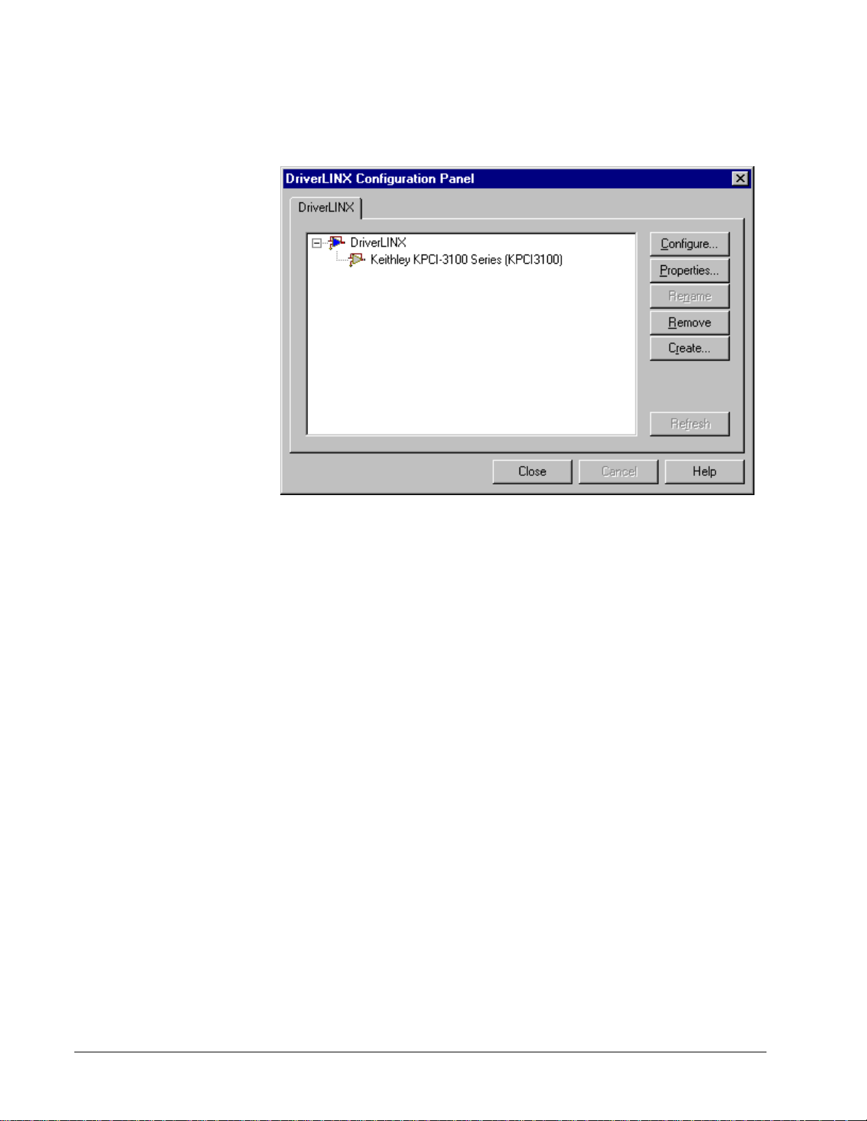
The installation program automatically starts the DriverLINX Configuration Panel.
To start it now, use the shortcut on the Windows Start Menu.
When you click the Configure… button on the DriverLINX Configuration Panel,
DriverLINX displays the Configure DriverLINX Device dialog. The dialog has a
page for each subsystem on the Keithley KPCI-3100 Series. The following sections
describe your choices in configuring DriverLINX to work with your board.
12 • Configuring the KPCI-3100 Series Keithley KPCI-3100 Series
Page 13
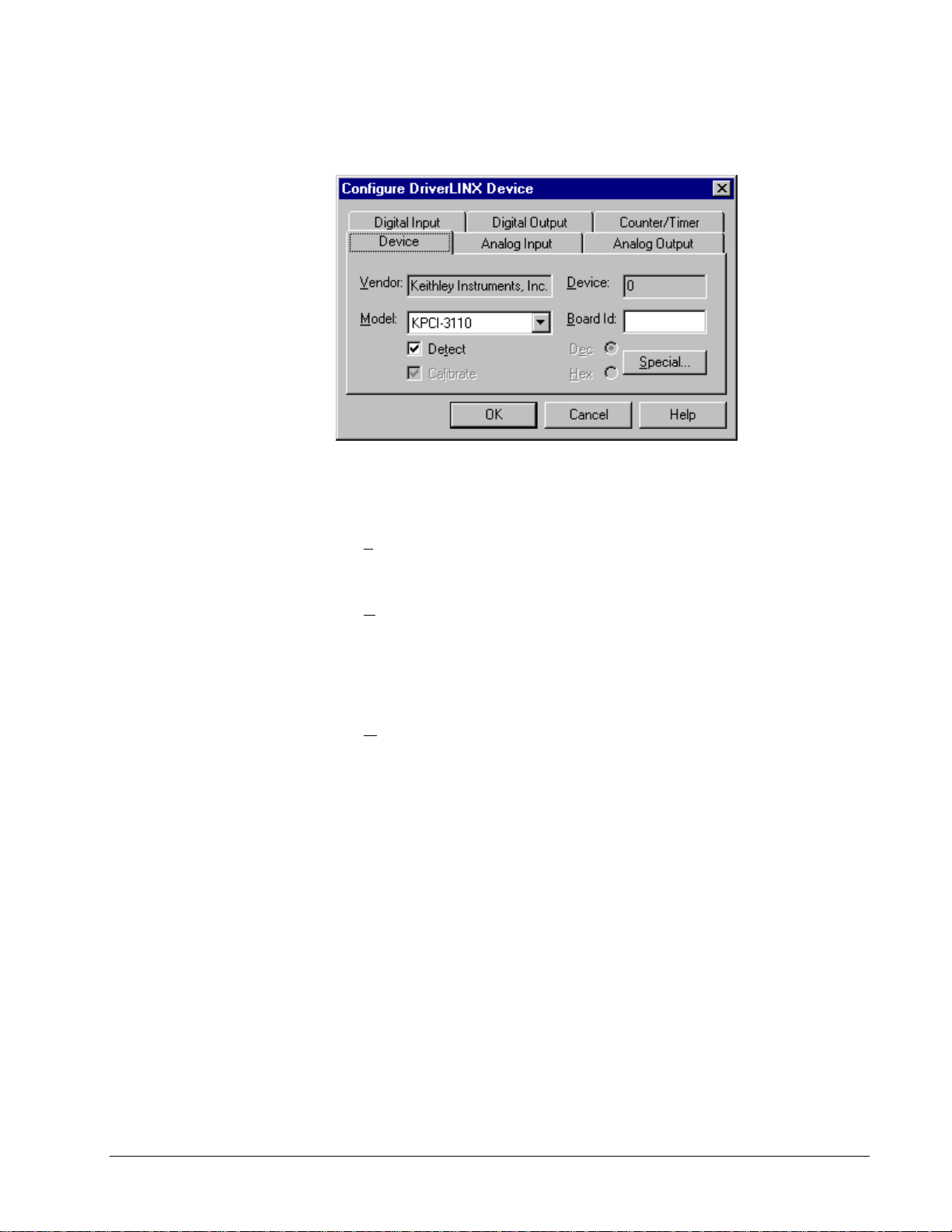
Device Subsystem Page
Use the Device subsystem page to tell DriverLINX the model name of, and,
optionally, the accessories connected to your KPCI-3100 Series board.
Vendor
The Vendor property displays “Keithley Instruments, Inc.” It is a read-only property.
Device
Windows NT
Windows 95/98
The Device property designates the Logical Device you are configuring. It is a readonly property. To change it, first save (OK) or quit (Cancel) the current
configuration. Then select or create a new Logical Device using the DriverLINX
Configuration Panel.
Model
The Model property selects or indicates the hardware model of the board you’re
configuring.
Select one of the following models:
KPCI-3101
KPCI-3102
KPCI-3103
KPCI-3104
KPCI-3110
KPCI-3116
Windows 95 automatically determines the model of your board so DriverLINX
disables Model selection.
Board Id
The KPCI-3100 Series boards do not have unique serial numbers that DriverLINX
can use to match a Logical Device to a board while loading the driver. Under
Windows 95/98, DriverLINX can match a Logical Device to a board based on the
Keithley KPCI-3100 Series Configuring the KPCI-3100 Series • 13
Page 14
model and bus slot. Under Windows NT, DriverLINX matches a Logical Device to a
board based on model only.
Windows NT
Windows 95/98
DriverLINX does not use the Board Id property.
DriverLINX assigns a Board Id based on the model and bus slot.
Detect
The Detect property enables and disables DriverLINX’s hardware detection and
testing algorithms. For maximum system reliability, always leave this check-bo x
marked.
Calibrate
The Calibrate property enables and disables hardware auto-calibration. This option
is grayed-out for the KPCI-3100 Series because it does not support automatic
calibration.
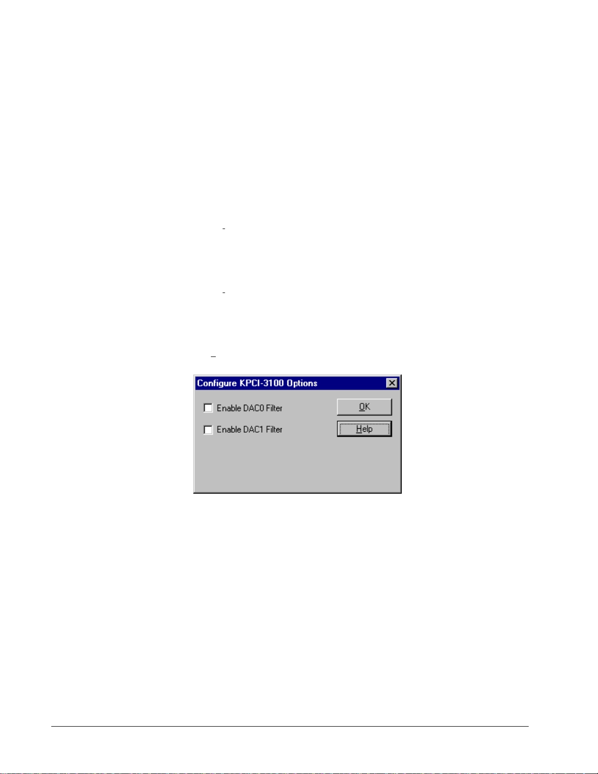
Special…
The Special… button displays the following dialog box of KPCI-3100 Series-specific
configuration options:
Note: The Filter settings apply only to model KPCI-3116.
Enable DAC Filters
Model KPCI-3116 has 20 kHz filters on its analog outputs that you can configure as
initially enabled or disabled. Applications can use the default configuration or
change the setting programmatically.
To enable the filters as the default configuration, perform the following steps:
1. In the Configure KPCI-3100 Options dialog box, check the Enable
DAC0 Filter box for Logical Channel 0
2. In the Configure KPCI-3100 Options dialog box, check the Enable
DAC1 Filter box for Logical Channel 1
14 • Configuring the KPCI-3100 Series Keithley KPCI-3100 Series
Page 15
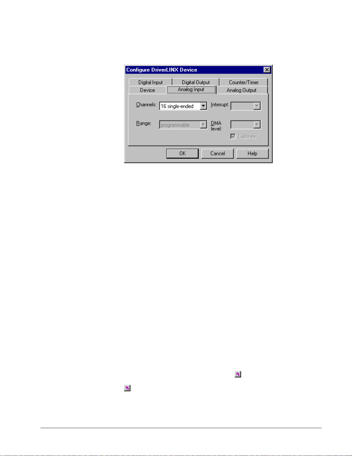
Analog Input Subsystem Page
Use the Analog Input subsystem page to choose between single-ended or differential
analog input channels as a default configuration.
Channels
On the KPCI-3100 Series, each Analog Input channel can use single-ended or
differential termination modes. When configuring the Analog Input Subs ys tem, you
choose a default configuration for all channels. Applications can use the default
configuration or specify the termination mode for each channel that it uses. This
scheme supports applications that use KPCI-3100-specific features as well as those
that use only generic features. For applications that do specify the termination mode,
configure the subsystem for single-ended channels so that all channels are available.
For information on programming the termination mode, see “Analog Input
Channels” on page 50.
Range
The analog input ranges for the KPCI-3100 Series are fully software programmable.
DriverLINX grays out this property in the configuration dialog.
Interrupt
The KPCI-3100 Series does not use interrupts. DriverLINX disables this property.
DMA
The KPCI-3100 Series does not use DMA channels for direct memory transfers. PCI
devices use bus mastering for DMA.
Calibrate
The KPCI-3100 Series supports manual calibration only. You can start the
calibration utility from the Windows Start menu
.
Keithley KPCI-3100 Series Configuring the KPCI-3100 Series • 15
Page 16

Analog Output Subsystem Page
Use the Analog Output subsystem page to set or view the initial output voltages.
Channels
Lists the analog output channels on the board and selects a channel for the Volts and
Initialize properties.
Range
The analog output ranges for the KPCI-3100 Series are fully software
programmable. DriverLINX grays out this property in the configuration dialog.
Volts
The Initialization Value property specifies the analog output value DriverLINX will
write to the selected Logical Channel upon hardware initialization. DriverLINX only
writes this value if you enable the In
itialize check box.
Interrupt
The KPIC-3100 Series does not use interrupts. DriverLINX disables this property.
DMA
The KPCI-3100 Series does not use DMA channels for direct memory transfers.
DriverLINX disables this property.
Initialize
Checking the In itialize check box instructs DriverLINX to use the Volts property for
to initialize the selected analog output channel.
16 • Configuring the KPCI-3100 Series Keithley KPCI-3100 Series
Page 17

Digital Input Subsystem Page
Use the Digital Input subsystem page to set configurable d igital channels as input or
output.
Channels
The Channels property allows you to select a Logical Channel for configuration or
viewing the channel’s range.
The KPCI-3100 Series supports both fixed and configurable digital channels.
DriverLINX defines the following Logical Channels for the KPCI-3100 Series
Digital Input Subsystem:
Models KPCI-3101/02/03/04
Logical
Channel
0 Digital Input/Output Digital I/O Bank A 0 … 7
1 Digital Input/Output Digital I/O Bank B 0 … 7
2 Digital Input/Output Digital I/O Bank C 0 … 6
3 External Clock External A/D Sample Clock Input
4 External Trigger External A/D TTL Trigger
Models KPCI-3110/16
Logical
Channel
0 Digital Input/Output Digital I/O Bank A 0 … 7
1 Digital Input/Output Digital I/O Bank B 0 … 7
2 External Clock External A/D Sample Clock Input
3 External Trigger External A/D TTL Trigger
DriverLINX
Function
DriverLINX
Function
KPCI-3100 Series External
Connector
External D/A Sample Clock Input
External D/A TTL Trigger
KPCI-3100 Series External
Connector
External D/A Sample Clock Input
External D/A TTL Trigger
Keithley KPCI-3100 Series Configuring the KPCI-3100 Series • 17
Page 18

Range
The Range property specifies the supported digital input range for the selected
Logical Channel. This is a read-only property.
Interrupt
The KPCI-3100 Series does not use interrupts. DriverLINX disables this property.
DMA
The KPCI-3100 Series does not use DMA channels for direct memory transfers.
DriverLINX disables this property.
Configuration Setup
The Conf igur at i on Setup property specifies the hardware configuration of the digital
I/O ports. Logical Channels 0 through 1 are configurable as input or output. Enter 1
to initially configure the selected channel as input or 0 to configure it as output and
check the Initialize box.
Initialize
Checking the In itialize check box instructs DriverLINX to use the Configuration
S
etup property to configure the selected digital I/O channel.
18 • Configuring the KPCI-3100 Series Keithley KPCI-3100 Series
Page 19
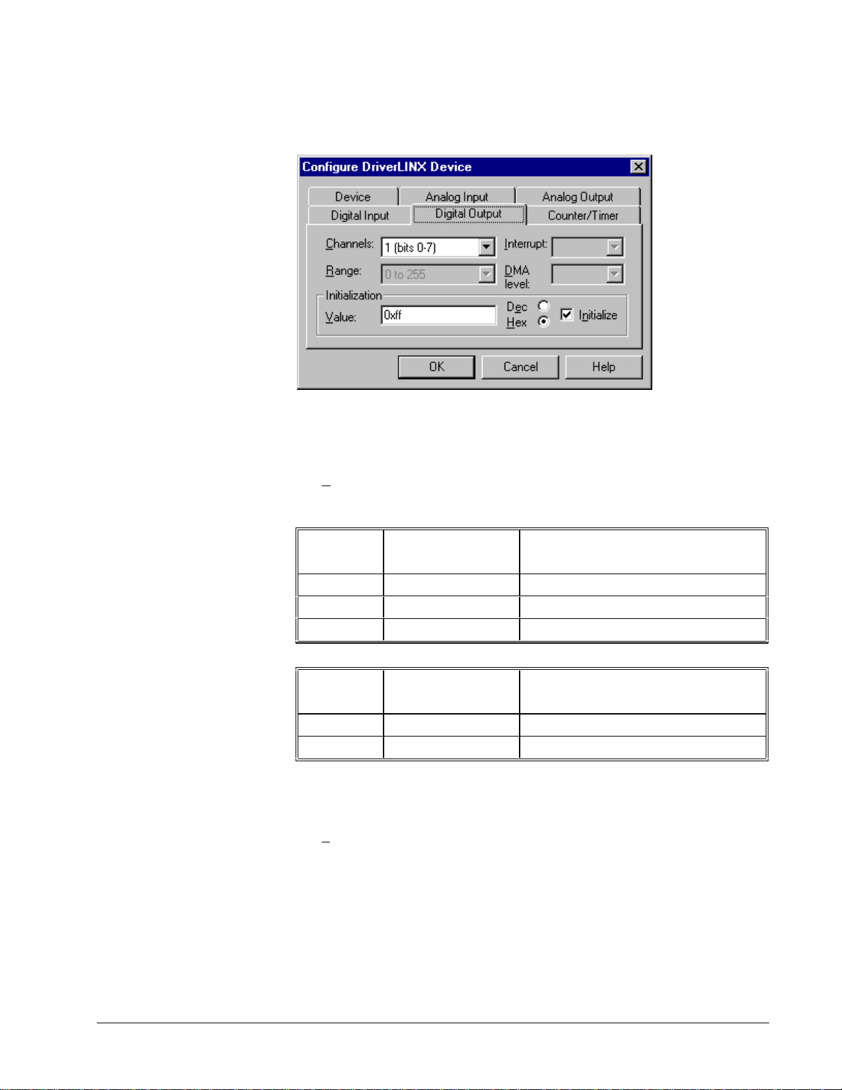
Digital Output Subsystem Page
Use the Digital Output subsystem page to change the default digital outp ut port
initialization values.
Channels
The Channels property allows you to select a Logical Channel for initialization or
viewing the channel’s range.
Models KPCI-3101/02/03/04
Logical
Channel
0 Digital Input/Output Digital I/O Bank A 0 … 7
1 Digital Input/Output Digital I/O Bank B 0 … 7
2 Digital Input/Output Digital I/O Bank C 0 … 6
Models KPCI-3110/16
Logical
Channel
0 Digital Input/Output Digital I/O Bank A 0 … 7
1 Digital Input/Output Digital I/O Bank B 0 … 7
DriverLINX
Function
DriverLINX
Function
KPCI-3100 Series External
Connector
KPCI-3100 Series External
Connector
Range
The Range property specifies the supported digital output range for the selected
Logical Channel. This is a read-only property.
Interrupt
The KPIC-3100 Series does not use interrupts. DriverLINX disables this property.
Keithley KPCI-3100 Series Configuring the KPCI-3100 Series • 19
Page 20

DMA
The KPCI-3100 Series does not use DMA channels for direct memory transfers.
DriverLINX disables this property.
Initialization Value
The Initialization Value property specifies the digital output value DriverLINX will
write to the selected Logical Channel upon hardware initialization. DriverLINX only
writes this value if you enable the In
itialize check box.
Initialize
Checking the In itialize check box instructs DriverLINX to use the Initialization
V
alue property for digital output port initialization.
Dec
This check box converts the Initialization Value property to decimal.
Hex
This check box converts the Initialization Value property to hexadecimal .
20 • Configuring the KPCI-3100 Series Keithley KPCI-3100 Series
Page 21

Counter/Timer Subsystem Page
Use the Count er/Timer subsystem page to view the clock source frequency.
Resolution
The Resolution property specifies the clock frequency of the master oscillator. All
models have a 20 MHz clock source for pacing input/output tasks and counter/timer
functions.
Interrupt
The KPIC-3100 Series does not use interrupts. DriverLINX disables this property.
Keithley KPCI-3100 Series Configuring the KPCI-3100 Series • 21
Page 22

Page 23

Using the KPCI-3100 Series with
DriverLINX
Introduction
See the Analog I /O
Programming Guide for an
overview of DriverLINX
programming.
This chapter shows you how to set up and use KPCI-3100 Series hardware features
with DriverLINX.
The descriptions here use the Edit Service Request dialog for language and API
independence. For the correct syntax with the language you’re using, please see the
DriverLINX Technical Reference Manuals. For DriverLINX examples in your
programming language, please see the source code examples in the subdirectories of
your DriverLINX installation directory or on the original distribution media.
KPCI-3100 Series Hardware Features
The KPCI-3100 Series offers your data-acquisition application a wide variety of
useful features. Analog inputs support programmable gains, termination modes and
polarities, as well as digital and analog pre-, post- and about-triggering. Analog
outputs are waveform-q uality (on some models). Four of the count er/timers ar e useraccessible. DriverLINX accesses these features through its hardware independent
Applications Programming Interface (API).
The following table is a cross-reference between hardware features and the
DriverLINX features that access them.
Keithley KPCI-3100 Series Using the KPCI-3100 Series with DriverLINX • 23
Page 24

Hardware Feature DriverLINX Feature
Calibration of each analog input and
output range
Analog triggering Analog Input:
Digital triggering Analog Input:
DriverLINX provides a stand-alone
KPCI-3100 Calibration Utility.
• Analog Start Event (Post-
Triggering)
• Analog Stop Event (Pre-
and About-Triggering)
Analog Output:
• Analog Start Event (Post-
Triggering)
Digital Input:
• Analog Start Event (Post-
Triggering)
• Analog Stop Event (Pre-
and About-Triggering)
• Digital Start Event (Post-
Triggering)
Analog Output:
• Digital Start Event (Post-
Triggering)
Digital Input:
• Digital Start Event (Post-
Triggering)
• Digital Stop Event (Pre- and
About-Triggering)
Programmable single-ended or
differential termination modes
Programmable gains Analog Input Channel Gains
Waveform-quality analog outputs
(models KPCI-3110/16 only)
User-accessible counter/timers Counter/Timer Subsystem
Analog Input Channel Termination
Modes
Analog Output Subsystem
AO Recycle Mode (waveform
generation)
DriverLINX Hardware Model for KPCI-3100 Series
DriverLINX provides a portable, hardware-independent API for data-acquisition
boards while still allowing applications to access unique or proprietary hardware
features of specific products. To achieve this goal, DriverLINX maps a hardwareindependent, or abstract, data-acquisition model onto KPCI-3100 Series hardware
capabilities.
24 • Using the KPCI-3100 Series with DriverLINX Keithley KPCI-3100 Series
Page 25

The following sections describe how DriverLINX implements KPCI-3100 Series
hardware features as Subsystems, Modes, Operations, Events, Logical Channels,
Buffers, and Messages.
DriverLINX Subsystems
The KPCI-3100 Series supports the following DriverLINX subsystems:
1. Device—refers to a KPCI-3100 Series board as a whole.
2. Analog Input—refers to the analog input channels, clocks, and control
signals.
3. Analog Output—refers to the analog output channels, clocks, and
control signals.
4. Digital Input—refers to the digital input ports as well as 1-bit digital
control signals and external clock inputs.
5. Digital Output—refers to the digital output ports.
6. Counter/Timer—refers to the onboa r d counter/timer channels for
pacing analog input/output or performing measuring and waveform
generatio n functions.
DriverLINX Modes
Applications use modes in Service Requests to advise DriverLINX on their preferred
hardware data transfer technique. The DriverLINX modes fall into two general
classes:
• Foreground or synchronous mode s. The calling application does not
regain control until DriverLINX completes the Service Request.
DriverLINX supports this mode for simple, single value I/O operations
or software housekeeping functions that DriverLINX can complete
without a si gnificant del ay.
• Background or asynchronous modes. The calling application regains
control as soon as DriverLINX initiates the task. The calling
application must synchronize with the data-acquisition task using status
polling or DriverLINX’s messages (preferred). DriverLINX supports
this mode for buffered data transfers or for commands that require a
significant time to complete.
DriverLINX supports four modes with the KPCI-3100 Series for its commands
(Service Requests).
• Polled Mode—This is a foreground or synchronous operation.
DriverLINX supports this mode for simple, single-value I/O operations
that the data-acquisition board can complete without significant delay.
• Interrupt Mode—T his is a background or asynchronous operation.
DriverLINX transfers data between the computer’s memory and the
data-acquisition board using hardware interrupts and programmed I/O
transfers.
Keithley KPCI-3100 Series Using the KPCI-3100 Series with DriverLINX • 25
Page 26

• DMA Mode—This is a background or asynchronous operation.
DriverLINX programs the data-acquisition board to transfer data
between the computer’s memory and the board.
• Other Mode—This is a foreground or synchronous operation.
DriverLINX supports this mode for initialization, configuration,
calibration, data conversion, and timebase operations.
The following table summarizes the data acquisition modes that DriverLINX
supports for each subsystem with the Keithley KPCI-3100 Series.
Subsystem Polled Interrupt DMA Other
Analog Input
Analog
Output
Digital Input
Digital Output
Counter/Timer
Device
* Interrupt mode is simulated by the driver for compatibility with applications
written for other hardware.
á
á
á
á
á
KPCI-3100 Series Supported DriverLINX Modes.
á*
á*
á*
á á
á á
á á
á
á
á
DriverLINX Operations and Events
Applications construct DriverLINX data-acquisitio n tasks by combining a small
number of DriverLINX operations and events in many possible ways. The following
table summarizes the operations and events that DriverLINX supports for the
Keithley KPCI-3100 Series. Later sections for each DriverLINX subsystem will
describe the operations and events in more detail.
Note: In addition to the operations shown in the table below, all subsystems allow
the MESSAGE operation in any Mode.
26 • Using the KPCI-3100 Series with DriverLINX Keithley KPCI-3100 Series
Page 27
Subsystem Operation Events
Mode Timing Start Stop
Analog Input
Polled Start null null, cmd null, TC
Interrupt Start, Stop,
dig, rate cmd, ana
Status,
Convert
DMA Start, Stop,
dig, rate cmd, ana*, dig cmd, TC, ana*,
Status,
Convert
Other Initialize
Analog Output (models KPCI-3102/04/10/16 only)
Polled Start null null, cmd null, TC
Interrupt* Start, Stop,
dig, rate cmd, ana, dig cmd, TC
Status,
Convert
DMA* Start, Stop,
dig, rate cmd, ana, dig cmd, TC
Status,
Convert
Other Initialize
*
, dig cmd, TC, ana*,
dig
dig
Digital Input
Polled Start null null, cmd null, TC
Interrupt Start, Stop,
Status
DMA Start, Stop,
Status
Other Initialize,
rate cmd, ana*, dig cmd, TC, ana*,
dig
rate cmd, ana*, dig cmd, TC, ana*,
dig
DIO Setup
Configure
Digital Output
Polled Start null null, cmd null, TC
Other Initialize,
DIO Setup
Configure
Counter/Timer
Polled Start, Stop,
null, rate null, cmd null, TC
Status
Other Initialize,
Configure
Device
Other Initialize,
Capabilities
Allowed Operations and Events for KPCI-3100 Series Subsystems and Modes.
*
Models KPCI-3110/16 only.
Keithley KPCI-3100 Series Using the KPCI-3100 Series with DriverLINX • 27
Page 28

The following list explains the Event abbreviations in the preceding table:
• null—Null or None Event specifies when a Service Request does not
require an event
• cmd—Command Event specifies when DriverLINX starts or stops a
task on software command
• TC—Terminal Count Event specifies when DriverLINX processes all
data buffers once
• rate—Rate Event specifies how DriverLINX paces or clocks data
transfer
• dig—Digital Event specifies a trigger, clock, or other control signal to
pace, start, or stop a task
• ana—Analog Event specifies a trigger to start or stop a task
• DIO Setup—DIO Setup Event assigns a digital channel to either the
Digital Input or Digital Output Subsystem.
Logical Channels
DriverLINX designates the individually addressable hardware channels for each
subsystem as “Logical Channels.” Generally, the zero-based Logical Channel
numbering sequence closely follows the hardware manufacturer’s channel
numbering scheme.
In some cases, however, DriverLINX assigns Logical Channel numbers to hardware
features that users don’t commonly think of as “channels.” For instance, DriverLINX
commonly models external hardware clock input lines, external hardware trigger
input lines, and external interrupt inputs as 1-bit digital Log ical Channels. In other
cases, DriverLINX models subsystem-specific features, such as internal pacer
clocks, as members of a more general-purpose set of counter/timer channels.
For a list of DriverLINX assigned Logical Channel numbers, see the notes on each
supported subsystem.
Buffers
Applications usually use data buffers to exchange data between the application and
the data-acquisition hardware. When using data buffers, please note the following
points about DriverLINX’s data buffers:
• DriverLINX supports data-acquisition tasks with 1 to 255 data buffers
per task.
• DriverLINX imposes no size limits on a single buffer, although the
operating system or some hardware products may have size restrictions.
• User applications must allow DriverLINX to allocate all data buffers to
guarantee application portability to different hardware and opera ting
systems and to insure that the hardware can physically access the buffer
memory.
• User applications usually don’t have concurrent or immediate access to
the in-use data buffer while DriverLINX is executing a data-acquisition
task.
28 • Using the KPCI-3100 Series with DriverLINX Keithley KPCI-3100 Series
Page 29

Connecting Signals to the KPCI-3100 Series
The Keithley hardware manual describes the data and control signals for the KPCI3100 Series and the connector pinouts for these signals. This section summarizes
how DriverLINX numbers the I/O data signals and how DriverLINX uses the control
connections for external clock, trigger, and gating inputs.
Analog Input Subsystem Signals
The Analog Input subsystem has 16 or 32 analog inputs, depending on the model,
and an analog ground. You set the default subsystem configuration as 8 or 16
differential, or 16 or 32 single-ended channels. Applications can then use the default
configuration or request a specific configuration for each channel. (See “Analog
Input Channels” on page 50 for programming information.)
DriverLINX maps these connections to Logical Channels as shown in the following
table:
Models KPCI-3101/02/03/04
Physical
Channels
0 – 7 Differential Analog Input 0 … Analog Input 7
0 – 15 Single-ended Analog Input 0 … Analog Input 15
Models KPCI-3110/16
Physical
Channels
0 – 15 Differential Analog Input 0 … Analog Input 15
0 – 31 Single-ended Analog Input 0 … Analog Input 31
How DriverLINX maps analog input hardware channels to Logical Channels.
Analog Input Pacing, Triggering and Gating Signals
Analog input tasks can use only Counter/Timer Logical Channel 4 for pacing. The
clock sources can be internal or external. The KPCI-3100 Series does not support
gating for Analog Input tasks.
Connector Name Logical
Channels
0 – 7
Analog Input 0 Return … Analog Input 7
Return
0 – 15
Amp Low
Connector Name Logical
Channels
0 – 15
Analog Input 0 Return … Analog Input 15
Return
0 – 31
Amp Low
The Analog Input subsystem can use several control signals that DriverLINX defines
as external clocks and triggers as shown in the following table:
Keithley KPCI-3100 Series Using the KPCI-3100 Series with DriverLINX • 29
Page 30

Connector Name DriverLINX Usage
External A/D TTL
Trigger
External A/D Sample
Clock Input
Analog Trigger External trigger:
Analog Input External trigger:
External trigger:
• Digital Start Event (Post-Triggering)
• Digital Stop Event (Pre- and About-
Triggering)
External pacer clock:
• Burst Generator: External Clocking
Divided external pacer clock:
• Rate Generator: External Clocking
• Analog Start Event (Post-Triggering)
• Analog Stop Event (Pre- and About-
Triggering)
• Analog Start Event (Post-Triggering)
• Analog Stop Event (Pre- and About-
Triggering)
How DriverLINX uses analog input control signals.
Analog Output Subsystem Signals
The Analog Output subsystem, for models KPCI-3102, 3104, 3110 and 3116, has 2
analog differential output connections.
DriverLINX maps these connections to Logical Channels as shown in the following
table:
Models KPCI-3102/04/10/16
Physical
Channel
0 Analog Output 0+, Analog Output 0 Return 0
1 Analog Output 1+, Analog Output 1 Return 1
How DriverLINX maps analog output hardware channels to Logical Channels.
Analog Output Pacing, Triggering and Gating Signals
Analog output tasks on models KPCI-3110 and 3116 can use Counter/Timer Logical
Channel 5 for pacing with internal or external clock sources to produce waveform
quality signals. Models KPCI-3102 and 3104 support polled transfers only. The
KPCI-3100 Series does not support gating for Analog Output tasks.
The Analog Output subsystem can use several control signals that DriverLINX
defines as external clocks and gates as shown in the following table:
Connector Name Logical
Channel
30 • Using the KPCI-3100 Series with DriverLINX Keithley KPCI-3100 Series
Page 31

Connector Name DriverLINX Usage
External D/A TTL
Trigger
External D/A Sample
Clock Input
Analog Trigger External trigger:
Analog Input External trigger:
External trigger:
• Digital Start Event (Post-Triggering)
External pacer clock:
• Burst Generator: External Clocking
Divided external pacer clock:
• Rate Generator: External Clocking
• Analog Start Event (Post-Triggering)
• Analog Start Event (Post-Triggering)
How DriverLINX uses analog output control signals.
Digital Input Subsystem Signals
The Digital Input Subsystem has two or three digital inp ut/output ports, depending
on the model, as well as four control inputs which DriverLINX models as two 1-bit
logical digital input channels. DriverLINX maps these sig nals to Logical Channels as
shown in the following table:
Models KPCI-3101/02/03/04
Logical
Channel
0 Digital Input/Output Digital I/O Bank A 0 … 7
1 Digital Input/Output Digital I/O Bank B 0 … 7
2 Digital Input/Output Digital I/O Bank C 0 … 6
3 External Clock External A/D Sample Clock Input
4 External Trigger External A/D TTL Trigger
Models KPCI-3110/16
Logical
Channel
0 Digital Input/Output Digital I/O Bank A 0 … 7
1 Digital Input/Output Digital I/O Bank B 0 … 7
2 External Clock External A/D Sample Clock Input
3 External Trigger External A/D TTL Trigger
DriverLINX
Function
DriverLINX
Function
How DriverLINX maps digital input hardware channels to Logical Channels.
KPCI-3100 Series External
Connector
External D/A Sample Clock Input
External D/A TTL Trigger
KPCI-3100 Series External
Connector
External D/A Sample Clock Input
External D/A TTL Trigger
Keithley KPCI-3100 Series Using the KPCI-3100 Series with DriverLINX • 31
Page 32

Notes:
• If a channel is configured for output, reading it using the Digital Input
subsystem returns the last value written.
• The External Trigger channel is not available for reading but is
available for clocking and triggering.
• Applications can assign a configurable channel to either digital
subsystem using a Configure operation. (See “Di g ital Channel
Configuration” on page 74.)
Digital Input Pacing, Triggering and Gating Signals
Digital input tasks are either polled mode or DMA mode. In DMA mode, the board
uses the analog input circuitry to sample digital Banks A and B, and therefore
supports the same pacing and triggering options as for analog input.
The Digital Input subsystem can use several contro l signals that DriverLINX defines
as external clocks and gates as shown in the following table:
Connector Name DriverLINX Usage
External A/D TTL
External trigger:
Trigger
• Digital Start Event (Post-Triggering)
• Digital Stop Event (Pre- and About-
Triggering)
External pacer clock:
• Burst Generator: External Clocking
External A/D Sample
Divided external pacer clock:
Clock Input
• Rate Generator: External Clocking
Analog Tri gger
External trigger:
• Analog Start Event (Post-Triggering)
• Analog Stop Event (Pre- and About-
Triggering)
Analog Input External trigger:
• Analog Start Event (Post-Triggering)
• Analog Stop Event (Pre- and About-
Triggering)
How DriverLINX uses digital input control signals.
32 • Using the KPCI-3100 Series with DriverLINX Keithley KPCI-3100 Series
Page 33
Digital Output Subsystem Signals
The Digital Output Subsystem has two or three digital input /output ports, depending
on the model. DriverLINX maps these signals to Logical Channels as shown in the
following table:
Models KPCI-3101/02/03/04
Logical
Channel
0 Digital Input/Output Digital I/O Bank A 0 … 7
1 Digital Input/Output Digital I/O Bank B 0 … 7
2 Digital Input/Output Digital I/O Bank C 0 … 6
Models KPCI-3110/16
Logical
Channel
0 Digital Input/Output Digital I/O Bank A 0 … 7
1 Digital Input/Output Digital I/O Bank B 0 … 7
How DriverLINX maps digital output hardware channels to Logical Channels.
Notes:
• If a channel is configured for output, reading it (using the Digital Input
• Applications can assign a configurable channel to either digital
Digital Output Pacing, Triggering and Gating Signals
DriverLINX
Function
DriverLINX
Function
subsystem) returns the last value written.
subsystem using a Configure operation. (See “Di g ital Channel
Configuration” on page 74.)
KPCI-3100 Series External
Connector
KPCI-3100 Series External
Connector
Digital output tasks can use only polled mode and therefore have no pacing,
triggering or gating signals. However, the KPCI-3100 Series does support Dynamic
Digital Output from the Analog Input subsystem. For more information on this
feature, see “Writing Digital Output Channels with the Analog Input Subsystem” on
page 54.
Counter/Timer Subsystem Signals
The Counter/Timer subsystem has a Logical Channel for each of the counter/timer
chip’s six counter/timers. The first four have external clock, gate and output pins but
support only counter/timer tasks. The last two have only clock inputs but do support
pacing tasks on other subsystems.
Analog I/O tasks can use the board’s external trigger inputs (External A/D and D/A
TTL Triggers) for pacing instead of the output of a counter/timer, and the board’s
external clock inputs (External A/D or D/A Sample Clock Inputs) instead of the
internal clock.
Keithley KPCI-3100 Series Using the KPCI-3100 Series with DriverLINX • 33
Page 34

DriverLINX maps these signals as shown in the following table:
Model KPCI-3130
Logical
Channel
0 External Clock
How DriverLINX maps counter/timer hardware channels to Logical Channels.
DriverLINX
Function
(sample on DAC
overload)
KPCI-3130 Series External
Connector
+/- DAC Overload Sense Lines 0 … 7
34 • Using the KPCI-3100 Series with DriverLINX Keithley KPCI-3100 Series
Page 35

Device Subsystem
f
The following sections describe how DriverLINX implements Device Subsystem
features for the KPCI-3100 Series.
Device Modes
The Device Subsystem supports only DriverLINX’s Other mode for all operations.
Device Operations
The KPCI-3100 Series Device Subsystem supports the following DriverLINX
operations:
If another application is using
the same data-acquisition
board, DriverLINX will
prevent Device Initialization
rom interfering with another
application’s data-acquisition
tasks.
• Initialize—DriverLINX aborts all data-acqui sition tasks for every
subsystem controlled by the current application. DriverLINX then
initializes each subsystem.
• Capabilities—DriverLINX provides hardware-specific and
configuration information in the form of a Logical Device Descriptor
database. (If you are using the DriverLINX ActiveX controls, access
the Logical Device Descriptor with a DriverLINXLDD control rather
than with this operation.)
Keithley KPCI-3100 Series Using the KPCI-3100 Series with DriverLINX • 35
Page 36

Analog Input Subsystem
The following sections describe how DriverLINX implements Analog Input
Subsystem features for the KPCI-3100 Series.
Analog Input Modes
The Analog Input Subsystem supports the following modes:
• Polled—For single-value or single-scan analog input samples.
• Interrupt—For buffered transfers using programmed I/O.
• DMA—For buffered transfers using direct memory access.
• Other—For subsystem initialization and data conversion.
Analog Input Operations
The KPCI-3100 Series Analog Input Subsystem supports the following DriverLINX
operations:
• Initialize—aborts all active analog input da ta-acquisition tasks.
However, DriverLINX prevents one application from interfering with
another application’s data-acquisition tasks.
• Start—initiates a data-acquisition task using the Mode, Timing, Start,
and Stop Events, the Logical Channels, and the Buffers the application
specified in the Service Request.
• Status—reports the buffer position of the next sample that DriverLINX
will write into a buffer.
• Stop—terminates an analog input data-acquisition task.
• Message—displays a pop-up dialog box for the user containing the text
for the current DriverLINX error message.
36 • Using the KPCI-3100 Series with DriverLINX Keithley KPCI-3100 Series
Page 37

Analog Input Timing Events
Timing Events specify how the hardware paces or clocks the acquisition of analog
input samples. DriverLINX uses the Timing Event to program when the KPCI-3100
Series acquires the next analog input sample.
The KPCI-3100 Series supports the following Timing Events for analog input:
• None—Sampling requires no pacing as DriverLINX is acquiring only a
single value or scan.
• Rate—The KPCI-3100 Series supports fixed rate and burst mode
sampling using internal and external clocks.
None or Null Timing Event
The Null Event specifies that the task does not need a clock to determine when to
acquire the next sample.
Rate Timing Event
The KPCI-3100 Series supports the following Rate Events for analog input:
• Rate Generator—Generates a fixed rate clock with equal time
intervals between tics.
• Burst Generator—Generates a dual frequency clock with a fixed
number of tics at a high frequency separated by a time interval at a
lower frequency.
KPCI-3100 Series boards have a fixed 20
MHz master clock frequency. The sample period range depends on the model. All
models limit the period to
hardware manual for details.
1224− tics, or 838,860 µs (1.20 Hz). Consult your
Keithley KPCI-3100 Series Using the KPCI-3100 Series with DriverLINX • 37
Page 38

Rate Generator: Internal Clocking
An internally clocked Rate Generator produces a fixed rate clock with equal time
intervals between tics.
Period
Use an internally clocked rate generator when you want to acquire all analog input
samples at equally spaced time intervals.
For hardware independence,
specify the clock channel
using the symbolic constant,
DEFAULTTIMER, which
always maps to the default
Logical Channel for analog
input timing.
How to set up the KPCI-3100 Series for fixed rate sampling using an internal clock.
• Specify internal clocking using a Rate Generator on Channel 4 with
the Internal1 Clock source.
• The Period property specifies the time interval between samples in tics.
• The KPCI-3100 Series does not support gating the analog input pacing
clock. Therefore, only Disabled and NoConnect settings are valid for
the Gate property.
Rate Generator: External Clocking
An externally clocked Rate Generator produces a rate clock with unknown time
intervals between tics.
Period (ext clk)
38 • Using the KPCI-3100 Series with DriverLINX Keithley KPCI-3100 Series
Page 39

Use an externally clocked rate generator when you want to synchronize analog input
eriod. The value does not affect the external clock frequency,
samples with a recurrent external signal. In this mode, you need a separate external
clock tic for each analog sample you want to acquire.
How to set up the KPCI-3100 Series for fixed rate sampling using an external clock.
For hardware independence,
specify the clock channel
using the symbolic constant,
DEFAULTTIMER, which
always maps to the default
Logical Channel for analog
input timing.
Be sure that the external
clock source is TTL
compatible, 0 V minimum to
+5 V maximum!
• Specify external clocking using a Rate Generator on Channel 4 with
an External or External- Clock source.
• Specify a Period between the minimum and maximum external
clocking p
but DriverLINX requires a valid hardware value in case the application
requests a timebase operation and to optimize data transfer between the
driver and the application.
• The KPCI-3100 Series does not support gating the analog input pacing
clock. Therefore, only Disabled and NoConnect settings are valid for
the Gate property.
• Users should connect the external clock signal to the External A/D
Clock Input line.
• The frequency of the external clock must not exceed the maximum
sampling rate for the board.
Note: The hardware transfers samples in groups of 16 on models KPCI3101/02/03/04 and 32 on models KPCI-3110/16. Therefore, samples may be held on
the board for up to 31 external clock pulses after they are taken. When acquiring a
fixed numbe r of samples, ensure the e xt ernal clock continues until all desired
samples are transferred from the board.
Keithley KPCI-3100 Series Using the KPCI-3100 Series with DriverLINX • 39
Page 40
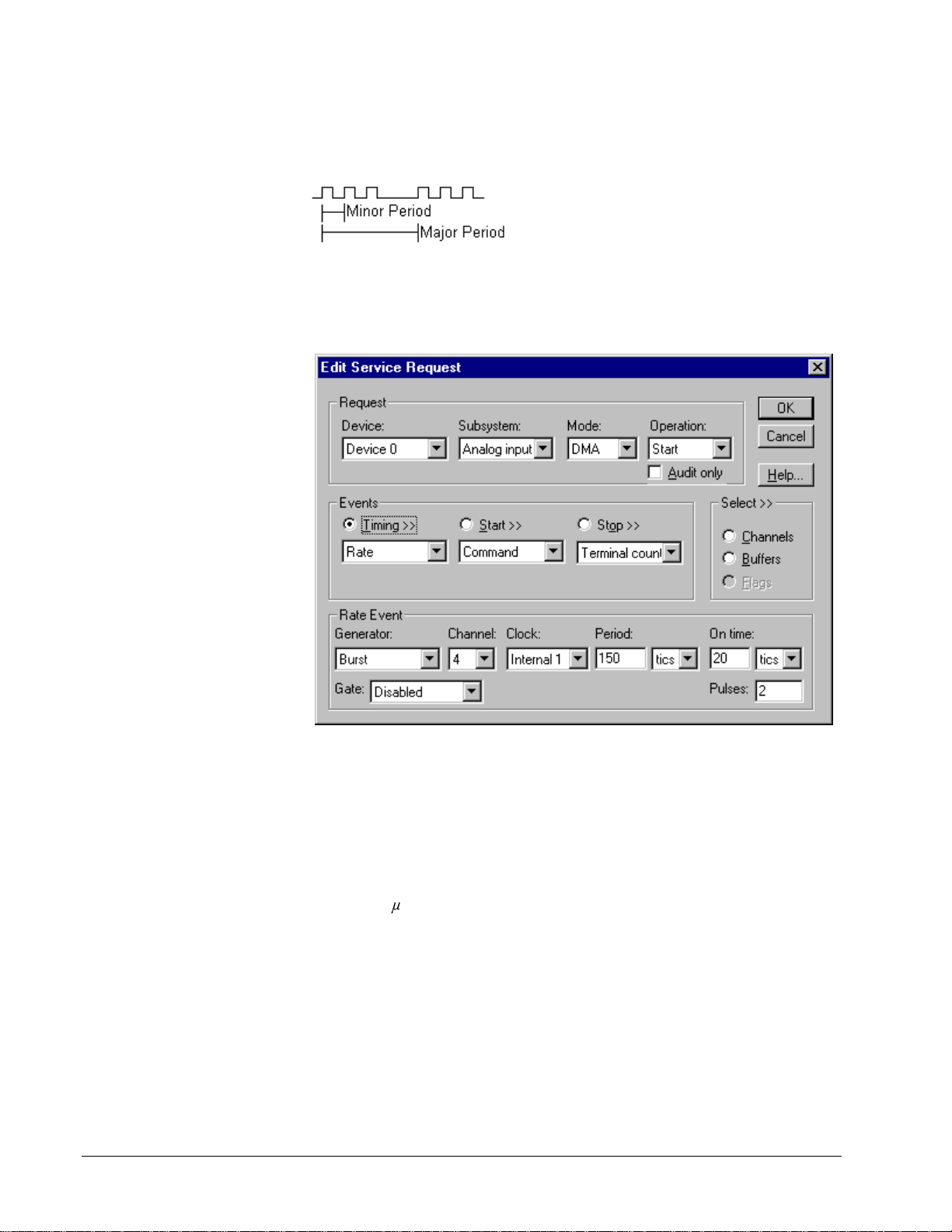
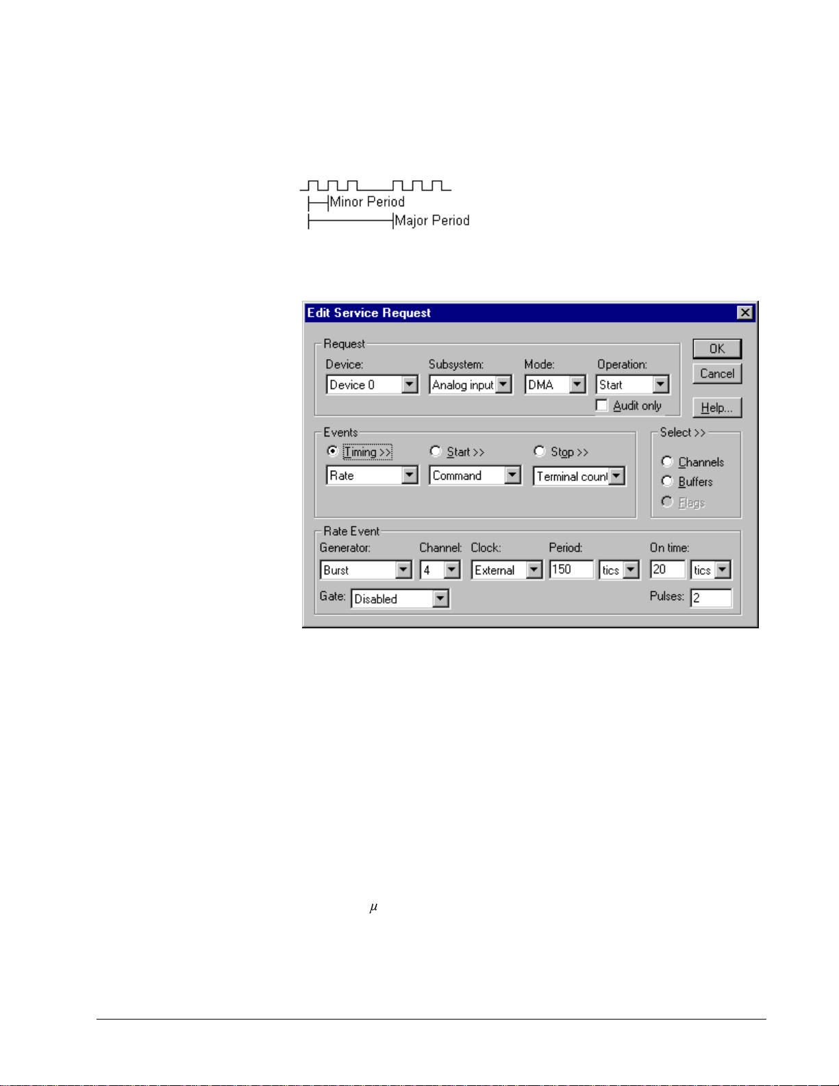
Burst Generator: Internal Clocking
An internally clocked Burst Generator produces a dual frequency clock with a fixed
number of tics at a high frequency repeated at a lower frequency.
Use an internally clocked rate generator when you want to acquire analog input
samples from a several channels at closely spaced time intervals and then repeat at
longer intervals.
How to set up the KPCI-3100 Series for burst mode sampling using an internal clock.
For hardware independence,
specify the clock channel
using the symbolic constant,
DEFAULTTIMER, which
always maps to the default
Logical Channel for analog
input timing.
40 • Using the KPCI-3100 Series with DriverLINX Keithley KPCI-3100 Series
• Specify internal clocking using a Burst Generator on Channel 4 with
the Internal1 Clock source.
• The Period property specifies the time interval between bursts in tics.
• The On time property specifies the time interval between samples.
Period must be greater than or equal to On time × Pulses + 40 tics (2
V.
• The KPCI-3100 Series does not support gating the analog input pacing
clock. Therefore, only Disabled and NoConnect settings are valid for
the Gate property.
• The Pulses property specifies how many channels the board samples in
each Period. Pulses must equal the number of channels in the channel
list multiplied by the desired number of scans per Period. The KPCI-
3100 Series can sample up to 256 scans per Period.
Page 41
Burst Generator: External Clocking
ue does not affect the external clock frequency,
property specifies how many channels the board samples in
An externally clocked Rate Generator produces a dual frequency clock with a fixed
number of tics at a high, internal frequency repeated at a lower, externally controlled
frequency.
Use an exter nally clocked burst generator when you want to synchronize a burst of
analog input samples with a recurrent external signal. In this mode, you need a
separate external clock tic for each burst of analog samples you want to acquire.
For hardware independence,
specify the clock channel
using the symbolic constant,
DEFAULTTIMER, which
always maps to the default
Logical Channel for analog
input timing.
How to set up the KPCI-3100 Series for burst mode sampling using an external clock.
• Specify external clocking using a Burst Generator on Channel 4 with
an External, External+ or External- Clock source.
• Specify a Period between the minimum and maximum external
clocking period. The val
but DriverLINX requires a valid hardware value in case the application
requests a timebase operation and to optimize data transfer between the
driver and the application.
• The KPCI-3100 Series does not support gating the analog input pacing
clock. Therefore, only Disabled and NoConnect settings are valid for
the Gate property.
• The On time property specifies the time interval between samples.
Period must be greater than or equal to On time × Pulses + 40 tics (2
V.
• The Pulses
each Period. Pulses must equal the number of channels in the channel
list multiplied by the desired number of scans per Period. The KPCI-
3100 Series can sample up to 256 scans per Period.
Keithley KPCI-3100 Series Using the KPCI-3100 Series with DriverLINX • 41
Page 42

Be sure that the external
clock source is TTL
compatible, 0 V minimum to
+5 V maximum!
• Users should connect the external clock signal to the External A/D
TTL Trigger line.
• The frequency of the external clock must not exceed the maximum
sampling rate for the board.
Note: The hardware transfers samples in groups of 16 on models KPCI3101/02/03/04 and 32 on models KPCI-3110/16. Therefore, samples may be held on
the board for up to 31 external clock pulses after they are taken. When acquiring a
fixed numbe r of samples, ensure the e xt ernal clock continues until all desired
samples are transferred from the board.
42 • Using the KPCI-3100 Series with DriverLINX Keithley KPCI-3100 Series
Page 43

Analog Input Start Events
Start Events specify when the KPCI-3100 hardware starts acquiring analog input
data.
The KPCI-3100 Series supports the following Start Events:
• None—Use this event when the DriverLINX ope r a tion does not require
a Start Event.
• Command—DriverLINX starts the task on software command, i.e., as
soon as DriverLINX finishes programming the KPCI-3100 hardware
for the task.
• Analog—The hardware starts acquiring analog input samples when the
hardware detects an analog signal satisfies the condition specified in
the Start Event.
• Digital—The hardware starts acquiring analog input samples when the
hardware detects the digital Logical Channel input satisfies the
condition specified in the Start Event.
None or Null Start Event
The Null Event specifies that the task does not need a Start Event to begin the task.
Command Start Event
The Command Event starts data acquisition as soon as DriverLINX has completed
programming the data-acquisition hardware with the task parameters.
Analog Start Event (Post-Triggering)
The KPCI-3100 Series can acquire analog input samples after the hardware detects
an analog trigger condition. Use post-triggering when you want to synchronize the
start of data acquisition with an external signal.
Keithley KPCI-3100 Series Using the KPCI-3100 Series with DriverLINX • 43
Page 44

How to set up the KPCI-3100 Series for post-triggered analog input.
Analog Start Events contain Channel, Gain, Polarity and Limit fields. The limits
determine the type of analog event (Level, Edge, Limit, or Band). The KPCI-3100
Series supports only edge triggering. A rising trigger occurs when a sample above
the limits follows a sample below the limits. Similarly, a falling trig ger o ccurs when
a sample below the limits follows a sample above the limits. As the board acquires
samples, it compares data from the specified Channel against the identical High and
Low Limits. The Polarity determines whether the trigger occurs on a risin g or falling
signal.
• Specify the Channel and Gain for a channel in the analog input
subsystem. For the KPCI-3100 Series, the analog event can use either
the Analog Trigger input or the first channel being sampled.
To trigger on the Analog Trigger input, specify 0 as the Channel and
any gain plus the OEM Gain Flag as the Gain. (The Edit Service
Request Dialog does not provide this optio n but it i s available
programmatically.) DriverLINX supports a programmable gain as a
convenience. The KPCI-3100 Series actually supports only a fixed
range of ±10Vwith an 8-bit resolution but you can still use Gain2Code
and Volts2Code to calculate the threshold settings.
To trigger on the first channel being sampled, specify the Channel and
Gain as in the first entry in the channel list.
• Specify the Polarity (or Slope) property as Pos for a rising trigger or
Neg for a falling trigger.
• Specify the Limit properties in hardware A/D codes as follows:
Type High Limit Low Limit
Edge Threshold Threshold
44 • Using the KPCI-3100 Series with DriverLINX Keithley KPCI-3100 Series
Page 45

Programming Tip: Use Volts2Code to easily convert volts to
hardware A/D codes for the threshold properties.
• Specify the Delay property as 0 or a positive number of samples to skip
after the trigger. The Delay value must be multiple of the number of
channels in the channel list.
Note:
• When the hardware detects the trigger, DriverLINX sends a StartEvent
message (or event). For more information on messages, see “Analog
Input Messages” on page 58.
Example: For a programming example, see AIATRG in your DrvLINX4\Source
folder.
Digital Start Event (Post-Triggering)
The KPCI-3100 can acquire analog input samples after the hardware detects a digital
trigger condition. Use post-triggering when you want to s ynchro nize the start of data
acquisition with an external signal.
How to set up the KPCI-3100 Series for post-triggered analog input.
Digital Start Events contain mask, pattern, and match fields. The mask is logically
ANDed with the digital input data on the Logical Channel and then compared with
the pattern for a match/mismatch.
• Specify the Channel as 3 for models KPCI-3110/16 or 4 for models
KPCI-3101/02/03/04. For hardware-independence, you can specify the
hardware external trigger channel by the symbolic constant,
DI_EXTTRG.
• Users should connect the external trigger signal to the External A/D
Trigger line.
Keithley KPCI-3100 Series Using the KPCI-3100 Series with DriverLINX • 45
Page 46

• Specify the Mask property as 1, or Bit 0, to indicate that DriverLINX
should only compare a 1-bit digital input value against the Pattern
property.
• Specify the Match property as N
• Specify the Pattern property as 0 for a rising, or positive, edge trigger
(≠0) or 1 for a falling, or negative, edge trigger (≠1).
• Specify the Delay property as 0 or a positive number of samples to skip
after the trigger. The Delay value must multiple of the number of
channels in the channel list.
Note:
• When the hardware detects the trigger, DriverLINX sends a StartEvent
message (or event). For more information on messages, see “Analog
Input Messages” on page 58.
Example: For a programming example, see AIDIGTRG in your DrvLINX4\Source
folder.
ot equals.
Analog Input Stop Events
Stop Events specify when the hardware stops acquiring analog input data.
The KPCI-3100 Series supports the following Stop Events:
• None—Use this event when the DriverLINX op eration does not require
a Stop Event.
• Command—DriverLINX stops the task on software command, i.e.,
when the application issues a Service Request with a Stop operation.
• Terminal count —Dr iverLINX stops the task after the data-acquisition
hardware has filled all the data buffers once.
• Analog—The hardware stops acquiring analog input samples when the
hardware detects an analog signal satisfies the condition specified in
the Start Event.
• Digital—The hardware stops acquiring analog input samples when the
hardware detects the digital Logical Channel input satisfies the
condition specified in the Stop Event.
None or Null Stop Event
The Null Event specifies that the task does not need a Stop Event to end the task.
Command Stop Event
The Command Event stops data acquisition when the user application changes the
Operation property in the Service Request to Stop and resubmits the Service Request
to DriverLINX.
In Stop-on-Command mode, DriverLINX continuously cycles through all the data
buffers filling them with analog input data from the data-acquisition hardware.
46 • Using the KPCI-3100 Series with DriverLINX Keithley KPCI-3100 Series
Page 47

Terminal Count Stop Event
The Terminal Count Event stops data acquisition after DriverLINX has filled all the
data buffers once with analog input data. Use Terminal Count when you want to
acquire a single scan or fixed amount of data.
Analog Stop Event (Pre- and About-Triggering)
The KPCI-3100 can acquire analog input samples until the hardware detects an
analog trigger condition. Use pre-triggering when you want to s ynchronize the end of
data-acquisition with an external signal. Use about-triggering when you want to
delay the end of data-acquisition a fixed number of samples after the trigger.
How to set up the KPCI-3100 Series for pre-triggered analog input.
Analog Stop Events contain Channel, Gain, Polarity and Limit fields. The limits
determine the type of analog event (Level, Edge, Limit, or Band). The KPCI-3100
Series supports only edge triggering. A rising trigger occurs when a sample above
the limits follows a sample below the limits. Similarly, a falling trig ger o ccurs when
a sample below the limits follows a sample above the limits. As the board acquires
samples, it compares data from the specified Channel against the identical High and
Low Limits. The Polarity determines whether the trigger occurs on a risin g or falling
signal.
• Specify the Channel and Gain for a channel in the analog input
subsystem. For the KPCI-3100 Series, the analog event can use either
the Analog Trigger input or the first channel being sampled.
To trigger on the Analog Trigger input, specify 0 as the Channel and
any gain plus the OEM Gain Flag as the Gain. (The Edit Service
Request Dialog does not provide this optio n but it i s available
programmatically.) DriverLINX supports a programmable gain as a
convenience. The KPCI-3100 Series actually supports only a fixed
range of ±10Vwith an 8-bit resolution but you can still use Gain2Code
and Volts2Code to calculate the threshold settings.
Keithley KPCI-3100 Series Using the KPCI-3100 Series with DriverLINX • 47
Page 48

To trigger on t he channels being sampled, specify the Channel and
Gain as in the first entry in the channel list. Note: When sampling
from more than one channel, you would typically use the Analog
Trigger input. This is because the hardware trigger monitors either the
Analog Trigger channel or the output of the ADC, which cannot
compare samples from the same channel while sa mpling from multiple
channels.
• Specify the Polarity (or Slope) property as Pos for a rising trigger or
Neg for a falling trigger.
• Specify the Limit properties in hardware A/D codes as follows:
Type High Limit Low Limit
Edge Threshold Threshold
Programming Tip: Use Volts2Code to easily convert volts to
hardware A/D codes for the threshold properties.
• Specify the Delay property as 0 for pre-triggering, or a positive number
of samples to obtain after the trigger for about-triggering. The Delay
value must be a multiple of the number of the number of channels in
the channel list.
The KPCI-3100 Series supports stopping immediately upon detection
of the trigger, rather than at the end of the current scan. To use this
feature specified the Delay property as 1.
Note:
• When the hardware detects the trigger, DriverLINX sends a StopEvent
message (or event) that identifies the buffer location of the last sa mple.
For more information on messages, see “Analog Input M essages” on
page 58.
Example: For a programming example, see AISTPTRG in your DrvLINX4\Source
folder.
Digital Stop Event (Pre- and About-Triggering)
The KPCI-3100 can acquire analog input samples until the hardware detects a digital
trigger condition. Use pre-triggering when you want to synchronize the end of data
acquisition with an external signal.
48 • Using the KPCI-3100 Series with DriverLINX Keithley KPCI-3100 Series
Page 49

How to set up the KPCI-3100 Series for pre-triggered analog input.
Digital Stop Events contain mask, pattern, and match fields. The mask is logically
ANDed with the digital input data on the Logical Channel and then compared with
the pattern for a match/mismatch.
• Specify the Channel as 3 for models KPCI-3110/16 or 4 for models
KPCI-3101/02/03/04. For hardware-independence, you can specify the
hardware external trigger channel by the symbolic constant,
DI_EXTTRG.
• Users should connect the external trigger signal to the External A/D
TTL Trigger line.
• Specify the Mask property as 1, or Bit 0, to indicate that DriverLINX
should only compare a 1-bit digital input value against the Pattern
property.
• Specify the Match property as N
ot equals.
• Specify the Pattern property as 0 for a rising, or positive, edge trigger
(≠0) or 1 for a falling, or negative, edge trigger (≠1).
• Specify the Delay property as 0 for pre-triggering, or a positive number
of samples to obtain after the trigger for about-triggering. The Delay
value must be a multiple of the number of channels in the channel list.
The KPCI-3100 Series supports stopping immediately upon detection
of the trigger, rather than at the end of the current scan. To use this
feature specified the Delay property as 1.
Note:
• When the hardware detects the trigger, DriverLINX sends a StopEvent
message (or event) that identifies sample following the tri gger . For
more information, see “Analog Input Messages” on page 58.
Keithley KPCI-3100 Series Using the KPCI-3100 Series with DriverLINX • 49
Page 50
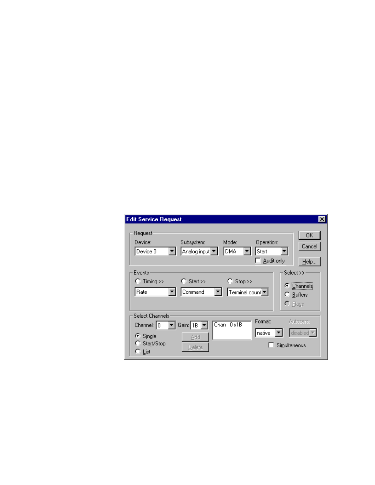
Example: For a programming example, see AIDSTPTG in your DrvLINX4\Source
folder.
Analog Input Channels
The KPCI-3100 Series models support a variety of channel gains with differential or
single-ended termination modes. The Logical Device configuration sets the default
termination mode for analog input channels. An application can request a particular
termination mode for each channel it uses. The channel gains are also application
selectable.
The KPCI-3100 Series allows applications to specify the analog channels using three
techniques:
• Start Channel—Acq uire data fr om a single channel.
• Start/Stop Channel Range—Acquire data from a consecutive range of
channels.
• Channel List—Acquire data from a list of channels.
Single Channel Analog Input
In single channel mode, the KPCI-3100 Series acquires all data from one channel at
the specified gain.
How to set up the KPCI-3100 Series for sampling on a single channel.
50 • Using the KPCI-3100 Series with DriverLINX Keithley KPCI-3100 Series
Page 51

Multi-channel Analog Input Range
In multi-channel range mode, the KPCI-3100 Series acquires data from a
consecutive range of analog channels.
• The Start Channel’s gain only applies to the first channel.
• DriverLINX uses the Stop Channel’s gain for all the other analog
channels in the range.
• The gains may vary but they must all be either unipolar or bipolar.
• All base channels must have the same termination mode.
• If the Start Channel is greater than the Stop Channel, the channel
sequence is [Start Channel,… Last Channel, 0,… Stop Channel], where
Last Channel is the highest numbered channel.
How to set up the KPCI-3100 Series for sampling on a consecutive range of channels.
Multi-channel Analog Input List
In multi-channel list mode, the KPCI-3100 Series acquires data from an arbitrary list
of analog channels.
• The channel-gain list may contain up to 1024 channels in any order.
The list may even include digital input channels; see “Read ing Digital
Input Channels with the Analog Input Subsystem” on page 53 for more
information on this feature.
• The list may repeat the same channel with the same or different gains.
• The gains may vary but they must all be either unipolar or bipolar.
• All base channels must have the same termination mode.
Keithley KPCI-3100 Series Using the KPCI-3100 Series with DriverLINX • 51
Page 52

How to set up the KPCI-3100 Series to sample from an arbitrary list of channels.
Analog Input Channel Gains
Each channel in a channel scan list has a gain code property to select the preamplifier gain when sampling that channel. The following tables sho w the
correspondence between the gain multiplier, the maximum input signal range, and
the gain code for each input range. Note: DriverLINX uses a negative (-) gain
multiplier to signify a bipolar (±) range.
Gain Range Gain Code
-1 ±10 V 0
-2 ±5 V 1
-4 ±2.5 V 2
-8 ±1.25 V 3
1 0 - 10 V 4
2 0 - 5 V 5
4 0 - 2.5 V 6
8 0 - 1.25 V 7
Gains, Ranges, and Hardware Gain Codes for KPCI-3100 Series.
Use the DriverLINX Gain2Code method to easily convert between the gains in the
above tables and Gain Codes. Using this method makes applications portable to
different hardware mod els that have the same anal og input ranges.
The KPCI-3100 Series can output digital data with each analog channel in the
channel list. DriverLINX uses the gain code to store this digital data. See “Writing
Digital Output Channels with the Analog Input Subsystem” on page 54 for more
information.
52 • Using the KPCI-3100 Series with DriverLINX Keithley KPCI-3100 Series
Page 53

Analog Input Channel Termination Modes
On the KPCI-3100 Series, Analog Input channels can use single-ended or differential
termination modes. When c onfiguring the Analog Input Subsystem, you choo s e a
default configuration for all channels. Applications can use the default configuratio n
or specify the termination mode for each task. This scheme supports applications that
use KPCI-3100-specific features as well as those that use only generic features.
Note: Choosing differential as the default configuration limits the number of
channels available. This number cannot be overridden. See "Analog Input Subsystem
Page" on page 15.
Each channel in a channel list has a gain code property. To specify a termination
mode for a channel, an application includes a termination mode flag in its gain code.
On the KPCI-3100 Series, a single task cannot sample base channels in different
termination modes.
The following table shows the flag value for each termination mode:
Termination mode Flag Value
Default Configuration CHAN_SEDIFF_DEFAULT = 0
13
21×
13
22×
13
23×
Single-ended
Differential
Digital
CHAN_SEDIFF_SE =
CHAN_SEDIFF_DIFF =
CHAN_DIGITAL =
“Digital” signifies a digital channel rather than an analog channel termination mode.
See “Reading Digital Input Channels with the Analog Input Subsystem” on page 53.
Note: The user chooses the default configuration on the Analog Input page of the
DriverLIN X Configura t ion Panel. See “Analog Input Subsys t em Page” on pa ge 15.
For example, an application that requires or knows a channel’s termination mode
obtains the gain code for a single-ended channel with a bipolar gain of 4, with:
Gain2Code (-4) + CHAN_SEDIFF_SE
// This code will work with only drivers that allow applications to specify a
termination mode.
An application that does not require or know a channel’s termination mode obtains
the gain code for a channel with a bipolar gain of 4, with:
Gain2Code (-4)
// This code will work with any board that supports bipolar ranges.
Reading Digital Input Channels with the Analog Input
Subsystem
The KPCI-3100 Series can sample digital input channels 0 and 1 along with analog
input channels. To use this feature, simply add channel 0 to the channel-gain list with
the gain code equal to the special value, CHAN_SEDIFF_DIG. Instead of returning
an analog channel’s A/D code in the data buffer, the board returns all sixtee n bits
from digital input channels 0 and 1. Note that the buffer will have analog data
interspersed with digital data.
Keithley KPCI-3100 Series Using the KPCI-3100 Series with DriverLINX • 53
Page 54

CHAN_OEM_FLAG is a
special value for the gain
field that indicates the
channel/gain entry has a
hardware-specific
meaning. The meaning is
not portable between
drivers. Its value is
15
2 .
Use it by OR-ing it with
other gain settings as
described for the driver.
Note: If you are sampling o nly digital input channels, you can achieve the same
result by sampling with the Digital Inp ut Subsystem. See “Digital Input Subsystem”
for details.
Writing Digital Output Channels with the Analog Input
Subsystem
The KPCI-3100 Series can also write digital output data while sampling each analog
input channel. Models KPCI-3101/02/03/04 support seven bits of dynamic digital
output. They share pins with Digital Input/Output Bank C. Models KPCI-3110/16
support only two bits of dynamic digital output.
To use this feature, merge the digital output data into the analog input channel list
by shifting it left 4 bits (multiply by 16) and OR-ing it with the gain field. Then OR
the symbolic constant CHAN_OEM_FLAG with the gain field.
Notes:
• If you set the CHAN_OEM_FLAG for any channel/gain list entry, it is
effectively set of all. Entries without the flag result in outputt ing zero
while the bo ard is sampling the corre sponding channel.
• On models KPCI-3101/02/03/04, you cannot write to Logical Channel 2
using the Digital Output subsystem while writing dynamic digital
output.
54 • Using the KPCI-3100 Series with DriverLINX Keithley KPCI-3100 Series
Page 55

Keithley KPCI-3100 Series Using the KPCI-3100 Series with DriverLINX • 55
Page 56

Analog Input Buffers
DriverLINX supports single-value, single-scan and buffered analog input.
• For single-value input, specify the Number of buffers as 0. The buffer
for a single value is the ioValue property.
• For single-scan input, specify the Number of buffers as 1 and the
number of Samples equal to the number of channels.
• For buffered input, specify the Number of buffers from 1 to 255 and
the number of Samples as desired.
For example, 500 sample s/2
channels = 250 is ok, but 500
samples/3 channels = 166.67
is incorrect.
How to set up the KPCI-3100 Series to store samples in buffers.
Buffer Size
An individual DriverLINX buffer may have any size as long as the buffer length
holds an integral number of channel scans (i.e., a multiple of the number of analog
input channels you’re acquiring). This restriction enforces the requirement that all
acquired channels have the same number of samples.
Buffer Usage
DriverLINX fills buffers sequentially until the task stops. During the task, only
complete buffers are available to the application. Except for tasks that stop on
terminal count, the last buffer may be only partially full. If the task stops on a trigger,
use the StopEvent message (or event) to determine the location of the last sample.
For other cases, use a Status operation to determine the location of the last sample.
Note: The hardware transfers samples in groups of 16 on models KPCI3101/02/03/04 and 32 on models KPCI-3110/16. Therefore, when stopping on
command, the last buffer may contain up to 31 invalid sampl e s before the stop
position reported by DriverLINX.
56 • Using the KPCI-3100 Series with DriverLINX Keithley KPCI-3100 Series
Page 57

Analog Input Data Coding
KPCI-3100 Series models return Analog Input hardware codes in right-justified
binary for unipolar ranges and right-justified offset binary for bipolar ranges.
DriverLINX refers to these coding schemes as the “native” format.
For any programmable gain, the KPCI-3100 models return hardware codes with the
ranges in the following tables:
KPCI-3101/02/03/04/10
Polarity Analog Input
Resolution
Analog Input
Hardware Code
Unipolar 12 bits 0 to 4095
Bipolar 12 bits 0 to 4095
Native Analog Input hardware codes for each KPCI-3100 Series polarity.
KPCI-3116
Polarity Analog Input
Resolution
Analog Input
Hardware Code
Unipolar 16 bits 0 to 65535
Bipolar 16 bits 0 to 65535
Native Analog Input hardware codes for each KPCI-3100 Series polarity.
15
10
5
0
-5
-10
-15
0 2048 4095
12-Bit Unipolar
12-Bit Bipolar
15
10
5
0
-5
-10
-15
0 32768 65635
KPCI-3100 Series native Analog Input Codes versus Voltage Range for a ten-volt range.
16-Bit Unipolar
16-Bit Bipolar
DriverLINX refers to the default hardware analog-coding scheme as the “native”
format. For computer arithmetic in a high-level language, the 16-bit two’s
complement integer format is general ly easier to use. Applic ations can use
Keithley KPCI-3100 Series Using the KPCI-3100 Series with DriverLINX • 57
Page 58

DriverLINX’s data conversion operations to transform an entire data buffer from
native format to many common integer and floating-point formats.
Analog Input Messages
For analog input operations, DriverLINX can report the following messages to the
application:
DriverLINX
Explanation
Message
Service Start DriverLINX has started the acquisition task.
Service Done DriverLINX has completed the acquisition task.
Start Event DriverLINX has detected the hardware start event.
Stop Event DriverLINX has detected the hardware stop event.
Buffer Filled DriverLINX has filled an analog input buffer.
Data Lost DriverLINX has detected an analog input data overrun
condition.
Critical Error DriverLINX has encountered an unexpected hardware
or software condition.
DriverLINX Event messages for analog input.
For detailed explanations of these messages see one of the following references:
• DriverLINX Technical Reference Manual for C/C++ users
• DriverLINX/VB Technical Reference Manual for VB or Delphi users
58 • Using the KPCI-3100 Series with DriverLINX Keithley KPCI-3100 Series
Page 59

Analog Output Subsystem
The following sections describe how DriverLINX implements Analog Output
Subsystem features for the KPCI-3100 Series.
Analog Output Modes
The Analog Output Subsystem supports the following modes:
• Polled—For single-value or single-scan analog output samples.
• Interrupt—For buffered transfers using programmed I/O.
• DMA—For buffered transfers using direct memory access.
• Other—For subsystem initialization and data conversion.
Note: On the KPCI-3100 Series, the driver performs all analog output data transfers
in the PCI bus’s slave mode. An application can specify DMA or Interrupt mode for
compatibility with other boards.
Analog Output Operations
The KPCI-3100 Series Analog Output Subsystem supports the following
DriverLINX operations:
• Initialize—aborts all active analog outp ut data-acquisition tasks.
However, DriverLINX prevents one application from interfering with
another application’s data-acquisition tasks.
• Start—initiates a data-acquisition task using the Mode, Timing, Start,
and Stop Events, the Logical Channels, and the Buffers the application
specified in the Service Request.
• Status—reports the buffer position of the next sample that DriverLINX
will write from a buffer.
• Stop—terminates an analog output data-acquisition task.
• Message—displays a pop-up dialog box for the user containing the text
for the current DriverLINX error message.
Keithley KPCI-3100 Series Using the KPCI-3100 Series with DriverLINX • 59
Page 60

Analog Output Timing Events
Timing Events specify how the hardware paces or clocks the writing of analog
output samples. DriverLINX uses the Timing Event to program when the KPCI-3100
Series writes the next analog output sample.
The KPCI-3100 Series supports the following Timing Events:
• None—Task requires no pacing as DriverLINX is writing only a single
value or scan.
• Rate—The KPCI-3100 Series supports fixed rate writing using internal
and external clocks. Also see: “Synchronizing an Analog Output Task
with an Analog Input Task” on page 63.
None or Null Timing Event
The Null Event specifies that the task does not need a clock to determine when to
write the next sample.
Rate Timing Event
The KPCI-3100 Series supports the following Rate Event for analog output:
• Rate Generator—Generates a fixed rate clock with equal time
intervals between tics.
KPCI-3100 Series boards have a fixed 20 MHz master clock frequency. The sample
period range depends on the model. All models limit the period to
838,860 µs (1.20 Hz). Consult your hardware manual for details.
1224− tics, or
60 • Using the KPCI-3100 Series with DriverLINX Keithley KPCI-3100 Series
Page 61

Rate Generator: Internal Clocking
An internally clocked Rate Generator produces a fixed rate clock with equal time
intervals between tics.
Period
Use an internally clocked rate generator when you want to write analog output
samples at equally spaced time intervals.
How to set up the KPCI-3100 Series for fixed rate writing using an internal clock.
For hardware independence,
specify the clock channel
using the symbolic constant,
DEFAULTTIMER, which
always maps to the default
Logical Channel for analog
output timing.
Also see: “Synchronizing an Analog Output Task with an Analog Input Task” on
page 63.
Keithley KPCI-3100 Series Using the KPCI-3100 Series with DriverLINX • 61
• Specify internal clocking using a Rate Generator on Channel 5 with
the Internal1 Clock source.
• The Period property specifies the time interval between samples in tics.
• The KPCI-3100 Series does not support gating the analog output
pacing clock. Therefore, only Disabled and NoConnect settings are
valid for the Gate property.
• In the Channel list, check Simultaneous when sampling bo t h analo g
output channels as the KPCI-3100 Series only supports writing both
channels at once.
Page 62

Rate Generator: External Clocking
An externally clocked Rate Generator produces a rate clock with unknown time
intervals between tics.
Period (ext clk)
Use an externally clocked rate generator when you want to synchronize analog
output samples with a recurrent external signal. In this mode, you need a separate
external clock tic for each analog scan you want to write.
How to set up the KPCI-3100 Series for fixed rate writing using an external clock.
Be sure that the external
clock source is TTL
compatible, 0 V minimum to
+5 V maximum!
62 • Using the KPCI-3100 Series with DriverLINX Keithley KPCI-3100 Series
• Specify external clocking using a Rate Generator on Channel 5 with
an External or External- Clock source. See “Counter/Timer
Subsystem” on page 98 for a description of clock sources.
• Users should connect the external clock signal to the External D/A
TTL Trigger line.
• Specify a Period between the minimum and maximum e xternal
clocking period. The value does not affect the external clock frequency,
but DriverLINX requires a valid hardware value in case the application
requests a timebase operation and to optimize data transfer between the
driver and the application.
• The frequency of the external clock must not exceed the maximum
sample rate for the board.
Page 63

• The KPCI-3100 Series does not support gating the analog output
pacing clock. Therefore, only Disabled and NoConnect settings are
valid for the Gate property.
• In the Channel list, check Simultaneous when sampling bo t h analo g
output channels as the KPCI-3100 Series only supports writing both
channels at once.
Synchronizing an Analog Output Task with an Analog Input
Task
The KPCI-3100 Series has several features that allow you to synchronize analog
output with analog input:
• Synchronized external clocking—You can set up separate analog
input and analog output tasks that use external clocking and connect the
clock signal to both the External A/D Sample Clock Input and the
External D/A Sample Clock Input.
• Synchronized triggering—You can set up separate analog input
and analog output tasks that use an external trigger and connect the
trigger signal to both the External A/D TTL Trigger and the External
D/A TTL Trigger.
Analog Output Start Events
Start Events specify when the hardware starts acquiring analog output data.
The KPCI-3100 Series supports the following Start Events:
• None—Use this event when the DriverLINX ope r a tion does not require
a Start Event.
• Command—DriverLINX starts the task on software command, i.e., as
soon as DriverLINX finishes programming the KPCI-3100 hardware
for the task.
• Analog—The hardware starts writing analog output samples when the
hardware detects an analog signal satisfies the condition specified in
the Start Event.
• Digital—The hardware starts writing analog output samples when the
hardware detects the digital Logical Channel input satisfies the
condition specified in the Start Event.
None or Null Start Event
The Null Event specifies that the task does not need a Start Event to begin the task.
Command Start Event
The Command Event starts data acquisition as soon as DriverLINX has completed
programming the data-acquisition hardware with the task parameters.
Analog Start Event (Post-Triggering)
The KPCI-3100 Series can write analog output samples after the hardware detects an
analog trigger condition. Use post-triggering when you want to synchronize the start
of data acquisition with an external signal.
Keithley KPCI-3100 Series Using the KPCI-3100 Series with DriverLINX • 63
Page 64

How to set up the KPCI-3100 Series for about-triggered analog output.
Analog Start Events contain Channel, Gain, Polarity and Limit fields. The limits
determine the type of analog event (Level, Edge, Limit, or Band). The KPCI-3100
Series supports only edge triggering. A rising trigger occurs when a sample above
the limits follows a sample below the limits. Similarly, a falling trig ger o ccurs when
a sample below the limits follows a sample above the limits. As the board acquires
samples, it compares data from the specified Channel against the identical High and
Low Limits. The Polarity determines whether the trigger occurs on a risin g or falling
signal.
• Specify the Channel and Gain for a channel in the analog input
subsystem. For the KPCI-3100 Series, the analog event can use only
the Analog Trigger input.
To trigger on the Analog Trigger input, specify 0 as the Channel and
any gain plus the OEM Gain Flag as the Gain. (The Edit Service
Request Dialog does not provide this optio n but it i s available
programmatically.) DriverLINX supports a programmable gain as a
convenience. The KPCI-3100 Series actually supports only a fixed
range of ±10Vwith an 8-bit resolution but you can still use Gain2Code
and Volts2Code to calculate the threshold settings.
• Specify the Polarity (or Slope) property as Pos for a rising trigger or
Neg for a falling trigger.
• Specify the Limit properties in hardware A/D codes as follows:
Type High Limit Low Limit
Edge Threshold Threshold
Programming Tip: Use Volts2Code to easily convert volts to
hardware A/D codes for the threshold properties.
64 • Using the KPCI-3100 Series with DriverLINX Keithley KPCI-3100 Series
Page 65

• Specify the Delay property as 0.
Note:
• When the hardware detects the trigger, DriverLINX sends a StartEvent
message (or event). For more information on messages, see “Analog
Output Messages” on page 72.
Digital Start Event (Post-Triggering)
The KPCI-3100 can write analog output samples after the hardware detects a digital
trigger condition. Use post-triggering when you want to s ynchro nize the start of data
acquisition with an external signal.
How to set up the KPCI-3100 Series for post-triggered analog output.
Digital Start Events contain mask, pattern, and match fields. The mask is logically
ANDed with the digital input data on the Logical Channel and then compared with
the pattern for a match/mismatch.
• Specify the Channel as 3 for models KPCI-3110/16 or 4 for models
KPCI-3101/02/03/04. For hardware-independence, you can specify the
hardware external trigger channel by the symbolic constant,
DI_EXTTRG.
• Users should connect the external trigger signal to the External D/A
Trigger line.
• Specify the Mask property as 1, or Bit 0, to indicate that DriverLINX
should only compare a 1-bit digital input value against the Pattern
property.
• Specify the Match property as N
ot equals.
• Specify the Pattern property as 0 for a rising, or positive, edge trigger
(≠0) or 1 for a falling, or negative, edge trigger (≠1).
Keithley KPCI-3100 Series Using the KPCI-3100 Series with DriverLINX • 65
Page 66

• Specify the Delay property as 0.
Note:
• When the hardware detects the trigger, DriverLINX sends a StartEvent
message (or event). For more information on messages, see “Analog
Output Messages” on page 72.
Example: For a programming example, see AODIGTRG in your
DrvLINX4\Source folder.
Analog Output Stop Events
Stop Events specify when the hardware stops acquiring analog output data.
The KPCI-3100 Series supports the following Stop Events:
• None—Use this event when the DriverLINX op eration does not require
a Stop Event.
• Command—DriverLINX stops the task on software command, i.e.,
when the application issues a Service Request with a Stop operation.
• Terminal count —Dr iverLINX stops the task after the data-acquisition
hardware has filled all the data buffers once.
None or Null Stop Event
The Null Event specifies that the task does not need a Stop Event to end the task.
Command Stop Event
The Command Event stops data acquisition when the user application changes the
Operation property in the Service Request to Stop and resubmits the Service Request
to DriverLINX.
In Stop-on-Command mode, DriverLINX continuously cycles through all the data
buffers, writing analog output data to the data-acquisition hardware.
Terminal Count Stop Event
The Terminal Count Event stops data acquisition after DriverLINX has filled all the
data buffers once with analog output data. Use Terminal Count when you want to
write a single scan or fixed amount of data.
66 • Using the KPCI-3100 Series with DriverLINX Keithley KPCI-3100 Series
Page 67
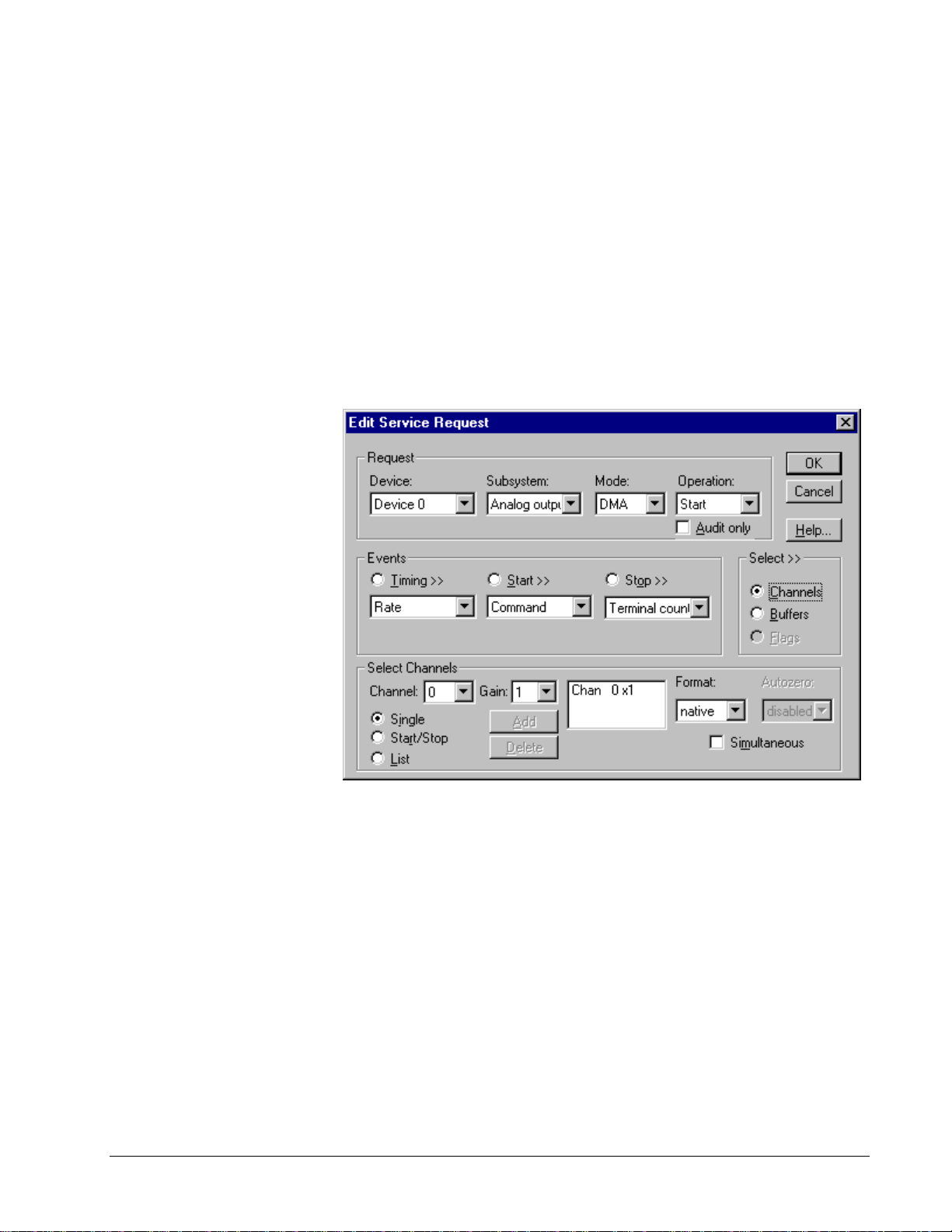
Analog Output Channels
The KPCI-3100 Series allows applications to specify the analog channels using three
techniques:
• Start Channel—Write data to a single chan nel.
• Start/Stop Channel Range— Write data to a consecutive range of
channels.
• Channel List—Write data to a list of channels.
Single Channel Analog Output
In single channel mode, the KPCI-3100 Series writes all data to one channel at the
specified gain.
How to set up the KPCI-3100 Series for writing to a single channel.
Multi-channel Analog Output Range
In multi-channel range mode, the KPCI-3100 Series writes data to a consecutive
range of anal og channel s.
• For the KPCI-3100 Series, when writing to both analog outputs, the
Start Channel must be channel 0 and the Stop Channel must be channel
1.
Keithley KPCI-3100 Series Using the KPCI-3100 Series with DriverLINX • 67
Page 68

How to set up the KPCI-3100 Series for writing to a consecutive range of channels.
Multi-channel Analog Output List
In multi-channel list mode, the KPCI-3100 Series writes data to an arbitrary list of
analog channels.
• For the KPCI-3100 Series, you can sample from either channel or from
channel 0 followed by channel 1.
How to set up the KPCI-3100 Series to write to an arbitrary list of channels.
68 • Using the KPCI-3100 Series with DriverLINX Keithley KPCI-3100 Series
Page 69

Analog Output Channel Gains
The KPCI-3100 Series models support a single channel gains for each digital-toanalog converter. The following table shows the correspondence between
DriverLINX gains, the maximum output signal range, and the gain code for each
output range. Note: DriverLINX uses a negative (-) gain valu e to signify a bipolar
(±) range.
KPCI-3102/04/10/16 Models
Gain Range Gain Code
-1 ±10 V 0
Gains, Ranges, and Gain Codes for the KPCI-3100 Series.
Use the DriverLINX Gain2Code method to easily convert between the gains in the
above tables and hardware Gain Codes.
Keithley KPCI-3100 Series Using the KPCI-3100 Series with DriverLINX • 69
Page 70
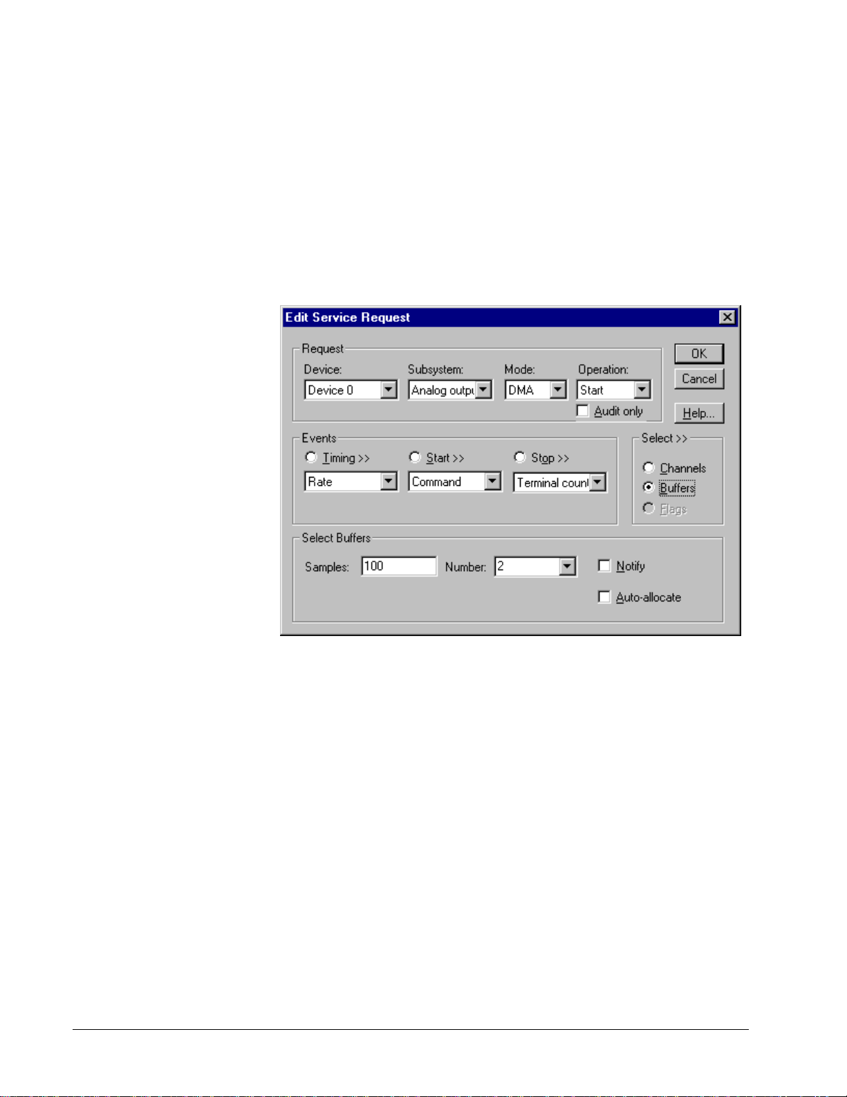
Analog Output Buffers
DriverLINX supports single-value, single-scan and buffered analog output.
• For single-value output, specify the Number of buffers as 0. The
buffer for a single value is the ioValue property.
• For a single-scan output, specify the Number of buffers as 1 and the
number of Samples equal to the number of channels.
• For buffered output, specify the Number of buffers from 1 to 255 and
the number of Samples as desired.
For example, 500 sample s/2
channels = 250 is ok, but 500
samples/3 channels = 166.67
is incorrect.
How to set up the KPCI-3100 Series to store samples in buffers.
Buffer Size
An individual DriverLINX buffer may have any size as long as the buffer length
holds an integral number of channel scans (i.e., a multiple of the number of analog
output channels you’re acquiring). This restriction enforces the requirement that all
acquired channels have the same number of samples.
Buffer Usage
DriverLINX writes from buffers sequentially until the task stops. Except for tasks
that stop on terminal count, the last buffer may be only partially used. If the task
stops on a trigger, use the StopEvent message (or event) to determine the location of
the last sample. For other cases, use a Status operation to determine the location of
the last sample.
70 • Using the KPCI-3100 Series with DriverLINX Keithley KPCI-3100 Series
Page 71

Analog Output Data Coding
KPCI-3100 Series uses the right-justified, offset binary format to encode analog
output data, as shown in the following table. DriverLINX refers to this coding
scheme as the “native” format.
Model Analog Output
Resolution
Analog Output
Hardware Code
KPCI-3102/04/10 12 bits 0 to 495
KPCI-3116 16 bits 0 to 65535
Native Analog Output hardware codes for the KPCI-3100 Series.
15
10
5
0
-5
-10
-15
0 4095 65535
KPCI-3100 Series native Analog Output Codes versus Voltage Range for a ten-volt range.
12-bit
16-bit
DriverLINX refers to the default hardware analog-coding scheme as the “native”
format. For computer arithmetic in a high- level language, the 16-bit two’s
complement integer format is general ly easier to use. Applic ations can use
DriverLINX’s data conversion operations to transform an entire data buffer from
many common integer and floating-point formats to native format.
Keithley KPCI-3100 Series Using the KPCI-3100 Series with DriverLINX • 71
Page 72

Analog Output Messages
For analog output operations, DriverLINX can report the following messages to the
application:
DriverLINX
Explanation
Message
Service Start DriverLINX has started the acquisition task.
Service Done DriverLINX has completed the acquisition task.
Start Event DriverLINX has detected a hardware start event.
Buffer Filled DriverLINX has filled an analog output buffer.
Critical Error DriverLINX has encountered an unexpected hardware
or software condition.
DriverLINX Event messages for analog output.
For detailed explanations of these messages see one of the following references:
• DriverLINX Technical Reference Manual for C/C++ users
• DriverLINX/VB Technical Reference Manual for VB or Delphi users
If your application does not need to change the output waveform during the task—
that is, does not need Buffer Filled messages—you may achieve a performance
benefit by usin g AO Rec ycle Mo d e .
AO Recycle Mode
Under certain conditions, the models KPCI-3110 and 3116 support AO Recycle
Mode (also known as “waveform generation”). Recycle mode allows the board to
generate a periodic waveform by recycling a buffer of up to 4096 samples. For
recycle mode, DriverLINX automatically promotes AO tasks meeting the following
criteria as specified in the Service Request to run from the DAC FIFO buffer in
recycle mode:
Service Request Property Value
Request mode Interrupt or DMA
Stop event type Command
Buffer notify flag False
Buffer samples 2 to 2048 per channel
Number of buffers 1
The advantages of using the DAC FIFO buffer for recycle mode analog output are:
72 • Using the KPCI-3100 Series with DriverLINX Keithley KPCI-3100 Series
Page 73

• The digital trigger operates in retrigger mode, enablin g you to
synchronize analog output with a recurring external signal.
• Traffic on the memory bus is significantly reduced at high output rates.
• The system response latency will be noticeably shortened.
• The analog output timing will be immune to traffic on the memory and
I/O buses.
The disadvantages are:
• You cannot change the analog output values while the analog output
task is running.
• There is a delay while DriverLINX loads entire wave fore into the
FIFO.
• Buffer-filled notification messages cannot be posted, as the hardware
does not permit detection of end-of-buffer conditions.
• The STATUS operation cannot provide the "number of buffers
processed" report.
Keithley KPCI-3100 Series Using the KPCI-3100 Series with DriverLINX • 73
Page 74

Digital Input Subsystem
The following sections describe how DriverLINX imple ments Digital Input
Subsystem features for the KPCI-3100 Series.
Digital Input Modes
The Digital Input Subsystem supports the following modes:
• Polled—For single-value or scan digital input samples.
• Interrupt—For buffered transfers using programmed I/O.
• DMA—For buffered transfers using direct memory access.
• Other—For subsystem initialization.
Digital Input Operations
The KPCI-3100 Series Digital Input Subsystem supports the following DriverLINX
operations:
• Initialize—aborts any active interrupt data-acquisition tasks and stops
the clock. DriverLINX prevents one application from interfering with
another application’s data-acquisition tasks.
• Configure—assigns a configurable digital channel to the input
subsystem.
• Start—initiates a data-acquisition task using the Mode, Timing, Start,
and Stop Events, the Logical Channels, and the Buffers the application
specified in the Service Request.
• Status—reports the buffer position of the next sample that DriverLINX
will write into a buffer.
• Stop—terminates a digital input data-acq uisit ion task.
• Message—displays a pop-up dialog box for the user containing the text
for the current DriverLINX error message.
Digital Channel Configuration
The KPCI-3100 Series has two or three configurable digital channels, depending on
the model. To use a digital channel as an input, you must first assign it to the Digital
Input Subsystem using the “Configure DriverLINX Device Dialog” (page 11) or by
using a Configure operat ion.
Special…To configure a digital channel submit a service request with following
settings:
• Subsystem—Digital Input or Digital Output
• Mode—Other
• Operation—Configure
• Timing Event—DIO Setup
• DIO Setup Channel—Channel number
74 • Using the KPCI-3100 Series with DriverLINX Keithley KPCI-3100 Series
Page 75

• DIO Setup Mode—DIO BASIC
For more information, see the following topics in the Digital I/O Programming
Guide:
• Configuring a Digital Port at Run Time
• Determining the Digital Port Configuration
Example: For a programming example, see DIOCNFIG in your DrvLINX4\Source
folder.
Digital Input Timing Events
Timing Events specify how the hardware paces or clocks the reading of Digital Input
samples. DriverLINX uses the Timing Event to program when the KPCI-3100 Series
reads the next digital input sample from the port.
The KPCI-3100 Series supports the following Timing Events:
• None—Input re quires no pa cing as Drive rLINX is reading only a
single value or scan.
• Rate—The KPCI-3100 Series supports fixed rate sampling using
internal and external clocks.
None or Null Timing Event
The Null Event specifies that the task does not need a clock to determine when to
read the next sample.
Note: Models KPCI-3101/02/03/04 require this mode when sampling Logical
Channel 2.
Rate Timing Event
The KPCI-3100 Series supports the following Rate Event for digital input:
• Rate Generator—Generates a fixed rate clock with equal time
intervals between tics.
KPCI-3100 Series boards have a fixed 20 MHz master clock frequency. The sample
period range depends on the model. All models limit the period to
838,860 µs (1.20 Hz). Consult your hardware manual for details.
Note: The KPCI-3100 Series can sample from only Logical Channels 0 and 1 in this
mode.
1224− tics, or
Keithley KPCI-3100 Series Using the KPCI-3100 Series with DriverLINX • 75
Page 76

Rate Generator: Internal Clocking
An internally clocked Rate Generator produces a fixed rate clock with equal time
intervals between tics.
Period
Use an internally clocked rate generator when you want to acquire all digital input
scans at equally spaced time intervals.
How to set up the KPCI-3100 Series for fixed rate sampling using an internal clock.
For hardware independence,
specify the clock channel
using the symbolic constant,
DEFAULTTIMER, which
always maps to the default
Logical Channel for digital
output timing.
• Specify internal clocking using a Rate Generator on Channel 4 with
the Internal1 Clock source.
• The Period property specifies the time interval between samples in tics.
• The KPCI-3100 Series does not support gating the analog input pacing
clock. Therefore, only Disabled and NoConnect settings are valid for
the Gate property.
Rate Generator: External Clocking
An externally clocked Rate Generator produces a rate clock with unknown time
intervals between tics.
Period (ext clk)
Use an externally clocked rate generator when you want to synchronize digital i nput
samples with a recurrent external signal. You need a separate external clock tic for
each scan you want to acquire.
76 • Using the KPCI-3100 Series with DriverLINX Keithley KPCI-3100 Series
Page 77

How to set up the KPCI-3100 Series for fixed rate sampling using an external clock.
riod. The value does not affect the external clock frequency,
For hardware independence,
specify the clock channel
using the symbolic constant,
DEFAULTTIMER, which
always maps to the default
Logical Channel for analog
input timing.
Be sure that the external
clock source is TTL
compatible, 0 V minimum to
+5 V maximum!
• Specify external clocking using a Rate Generator on Channel 4 with
an External or External- Clock source.
• Specify a Period between the minimum and maximum external
clocking pe
but DriverLINX requires a valid hardware value in case the application
requests a timebase operation and to optimize data transfer between the
driver and the application.
• The KPCI-3100 Series does not support gating the analog input pacing
clock. Therefore, only Disabled and NoConnect settings are valid for
the Gate property.
• Users should connect the external clock signal to the External A/D
Clock Input line.
• The frequency of the external clock must not exceed the maximum
sampling rate for the board.
Note: The hardware transfers samples in groups of 16 on models KPCI3101/02/03/04 and 32 on models KPCI-3110/16. Therefore, samples may be held on
the board for up to 31 external clock pulses after they are taken. When acquiring a
fixed numbe r of samples, ensure the e xt ernal clock continues until all desired
samples are transferred from the board.
Digital Input Start Events
Start Events specify when the KPCI-3100 Series hardware starts reading digital input
data.
The KPCI-3100 Series supports the following Start Events for digital input:
Keithley KPCI-3100 Series Using the KPCI-3100 Series with DriverLINX • 77
• None—Use this event when the DriverLINX op eration does not require
a Start Event.
Page 78

• Command—DriverLINX starts the task on software command, i.e., as
soon as DriverLINX finishes programming the KPCI-3100 hardware
for the task.
• Analog—The hardware starts acquiring digital input samples when the
hardware detects an analog signal satisfies the condition specified in
the Start Event.
• Digital—The hardware starts acquiring analog input samples when the
hardware detects the digital Logical Channel input satisfies the
condition specified in the Start Event.
None or Null Start Event
The Null Event specifies that the task does not need a Start Event to begin the task.
Command Start Event
The Command Event starts data acquisition as soon as DriverLINX has completed
programming the KPCI-3100 Series hardware with the task parameters.
Analog Start Event (Post-Triggering)
The KPCI-3100 Series can acquire digital input samples after the hardware detects
an analog trigger condition. Use post-triggering when you want to synchronize the
start of data acquisition with an external signal.
How to set up the KPCI-3100 Series for about-triggered analog input.
Analog Start Events contain Channel, Gain, Polarity and Limit fields. The limits
determine the type of analog event (Level, Edge, Limit, or Band). The KPCI-3100
Series supports only edge triggering. A rising trigger occurs when a sample above
the limits follows a sample below the limits. Similarly, a falling trig ger o ccurs when
a sample below the limits follows a sample above the limits. As the board acquires
samples, it compares data from the specified Channel against the identical High and
78 • Using the KPCI-3100 Series with DriverLINX Keithley KPCI-3100 Series
Page 79

Low Limits. The Polarity determines whether the trigger occurs on a risin g or falling
signal.
• Specify the Channel and Gain for a channel in the analog input
subsystem. For the KPCI-3100 Series, the analog event can use only
the Analog Trigger input.
To trigger on the Analog Trigger input, specify 0 as the Channel and
any gain plus the OEM Gain Flag as the Gain. (The Edit Service
Request Dialog does not provide this optio n but it i s available
programmatically.) DriverLINX supports a programmable gain as a
convenience. The KPCI-3100 Series actually supports only a fixed
range of ±10Vwith an 8-bit resolution but you can still use Gain2Code
and Volts2Code to calculate the threshold settings.
Specify the Polarity (or Slope) property as Pos for a rising trigger or
Neg for a falling trigger.
• Specify the Limit properties in hardware A/D codes as follows:
Type High Limit Low Limit
Edge Threshold Threshold
Programming Tip: Use Volts2Code to easily convert volts to
hardware A/D codes for the threshold properties.
• Specify the Delay property as 0 or a positive number of samples to skip
after the trigger. The Delay value must be multiple of the number of
channels in the channel list.
Note:
• When the hardware detects the trigger, DriverLINX sends a StartEvent
message (or event). For more information on messages, see “Digital
Input Messages” on page 89.
Digital Start Event (Post-Triggering)
The KPCI-3100 can acquire digital input samples after the hardware detects a digital
trigger condition. Use post-triggering when you want to s ynchro nize the start of data
acquisition with an external signal.
Keithley KPCI-3100 Series Using the KPCI-3100 Series with DriverLINX • 79
Page 80

How to set up the KPCI-3100 Series for post-triggered digital input.
Digital Start Events contain mask, pattern, and match fields. The mask is logically
ANDed with the digital input data on the Logical Channel and then compared with
the pattern for a match/mismatch.
• Specify the Channel as 3 for models KPCI-3110/16 or 4 for models
KPCI-3101/02/03/04. For hardware-independence, you can specify the
hardware external trigger channel by the symbolic constant,
DI_EXTTRG.
• Users should connect the external trigger signal to the External A/D
Trigger line.
• Specify the Mask property as 1, or Bit 0, to indicate that DriverLINX
should only compare a 1-bit digital input value against the Pattern
property.
• Specify the Match property as N
• Specify the Pattern property as 0 for a rising, or positive, edge trigger
(≠0) or 1 for a falling, or negative, edge trigger (≠1).
• Specify the Delay property as 0 or a positive number of samples to skip
after the trigger. The Delay value must multiple of the number of
channels in the channel list.
ot equals.
Digital Input Stop Events
Stop Events specify when the KPCI-3100 Series hardware stops reading digital input
data.
The KPCI-3100 Series supports the following Stop Events for digital input:
• None—Use this event when the DriverLINX op eration does not require
a Stop Event.
80 • Using the KPCI-3100 Series with DriverLINX Keithley KPCI-3100 Series
Page 81

• Command—DriverLINX stops the task on software command, i.e.,
when the application issues a Service Request with a Stop operation.
• Terminal count —DriverLINX stops the task after the KPCI-3100
Series hardware has filled all the data buffers once.
• Analog—The hardware stops acquiring digital input samples when the
hardware detects an analog signal satisfies the condition specified in
the Start Event.
• Digital—The hardware stops acquiring analog input samples when the
hardware detects the digital Logical Channel input satisfies the
condition specified in the Stop Event.
None or Null Stop Event
The Null Event specifies that the task does not need a Stop Event to end the task.
Command Stop Event
The Command Event stops data acquisition when the user application changes the
Operation property in the Service Request to Stop and resubmits the Service Request
to DriverLINX.
In Stop-on-Command mode, DriverLINX continuously cycles through all the data
buffers, filling them with digital input data fro m the data-acquisitio n hardware.
Terminal Count Stop Event
The Terminal Count Event stops data acq uisition after DriverLINX has read the
digital input data into all the data buffers once. Use terminal count when you wa nt to
read a fixed amount of data.
Analog Stop Event (Pre- and About-Triggering)
The KPCI-3100 can acquire digital input samples until the hardware detects an
analog trigger condition. Use pre-triggering when you want to s ynchronize the end of
data-acquisition with an external signal. Use about-triggering when you want to
delay the end of data-acquisition a fixed number of samples after the trigger.
Keithley KPCI-3100 Series Using the KPCI-3100 Series with DriverLINX • 81
Page 82

How to set up the KPCI-3100 Series for pre-triggered digital input.
Analog Stop Events contain Channel, Gain, Polarity and Limit fields. The limits
determine the type of analog event (Level, Edge, Limit, or Band). The KPCI-3100
Series supports only edge triggering. A rising trigger occurs when a sample above
the limits follows a sample below the limits. Similarly, a falling trig ger o ccurs when
a sample below the limits follows a sample above the limits. As the board acquires
samples, it compares data from the specified Channel against the identical High and
Low Limits. The Polarity determines whether the trigger occurs on a risin g or falling
signal.
• Specify the Channel and Gain for a channel in the analog input
subsystem. For the KPCI-3100 Series, the analog event can use only
the Analog Trigger input.
To trigger on the Analog Trigger input, specify 0 as the Channel and
any gain plus the OEM Gain Flag as the Gain. (The Edit Service
Request Dialog does not provide this optio n but it i s available
programmatically.) DriverLINX supports a programmable gain as a
convenience. The KPCI-3100 Series actually supports only a fixed
range of ±10Vwith an 8-bit resolution but you can still use Gain2Code
and Volts2Code to calculate the threshold settings.
• Specify the Polarity (or Slope) property as Pos for a rising trigger or
Neg for a falling trigger.
• Specify the Limit properties in hardware A/D codes as follows:
Type High Limit Low Limit
Edge Threshold Threshold
Programming Tip: Use Volts2Code to easily convert volts to
hardware A/D codes for the threshold properties.
82 • Using the KPCI-3100 Series with DriverLINX Keithley KPCI-3100 Series
Page 83
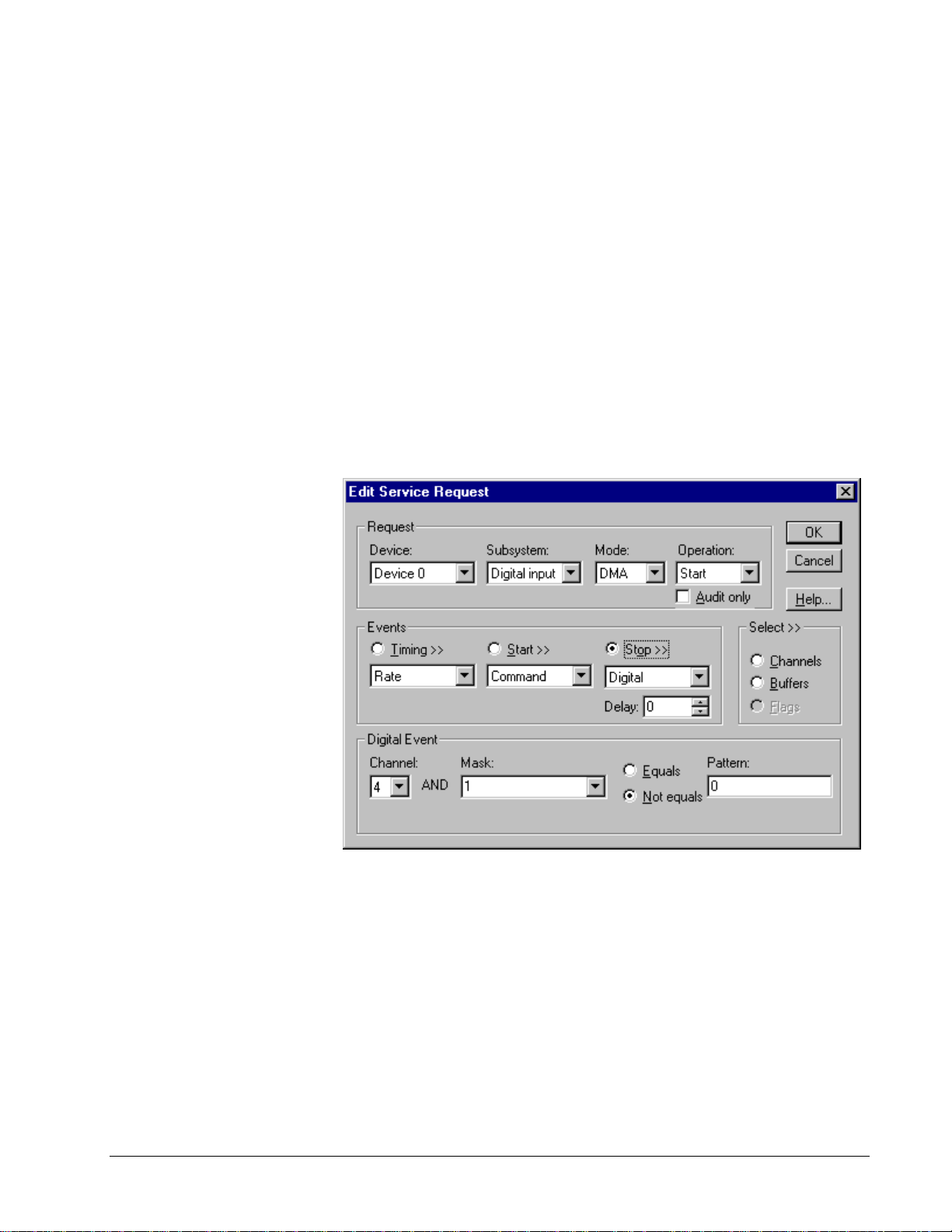
• Specify the Delay property as 0 for pre-triggering, or a positive number
of samples to obtain after the trigger for about-triggering. The Delay
value must be a multiple of the number of the number of channels in
the channel list.
The KPCI-3100 Series supports stopping immediately upon detection
of the trigger, rather than at the end of the current scan. To use this
feature specified the Delay property as 1.
Note:
• When the hardware detects the trigger, DriverLINX sends a StopEvent
message (or event) that identifies the buffer location of the last sa mple.
For more information on messages, see “Digital Input Messages” on
page 89.
Digital Stop Event (Pre- and About-Triggering)
The KPCI-3100 can acquire digital input samples until the hardware detects a digital
trigger condition. Use pre-triggering when you want to synchronize the end of data
acquisition with an external signal.
How to set up the KPCI-3100 Series for pre-triggered digital input.
Digital Stop Events contain mask, pattern, and match fields. The mask is logically
ANDed with the digital input data on the Logical Channel and then compared with
the pattern for a match/mismatch.
• Specify the Channel as 3 for models KPCI-3110/16 or 4 for models
KPCI-3101/02/03/04. For hardware-independence, you can specify the
hardware external trigger channel by the symbolic constant,
DI_EXTTRG.
• Users should connect the external trigger signal to the External A/D
TTL Trigger line.
Keithley KPCI-3100 Series Using the KPCI-3100 Series with DriverLINX • 83
Page 84

• Specify the Mask property as 1, or Bit 0, to indicate that DriverLINX
should only compare a 1-bit digital input value against the Pattern
property.
Note:
• Specify the Match property as N
ot equals.
• Specify the Pattern property as 0 for a rising, or positive, edge trigger
(≠0) or 1 for a falling, or negative, edge trigger (≠1).
• Specify the Delay property as 0 for pre-triggering, or a positive number
of samples to obtain after the trigger for about-triggering. The Delay
value must be a multiple of the number of channels in the channel list.
The KPCI-3100 Series supports stopping immediately upon detection
of the trigger, rather than at the end of the current scan. To use this
feature specified the Delay property as 1.
• When the hardware detects the trigger, DriverLINX sends a StopEvent
message (or event) that identifies sample following the tri gger . For
more information, see “Digital Input Messages” on page 89.
84 • Using the KPCI-3100 Series with DriverLINX Keithley KPCI-3100 Series
Page 85

Digital Input Channels
The KPCI-3100 Series allows applications to specify the digital channels using three
techniques:
• Start Channel—Acq uire data fr om a single channel.
• Start/Stop Channel Range—Acquire data from a consecutive range of
channels.
• Channel List—Acquire data from a list of channels.
Digital Input Logical Channels
The KPCI-3100 Series supports two or three configurable digital channels,
depending on the model. DriverLINX defines the following Logical Channels for the
KPCI-3100 Series Digital Input Subsystem:
Models KPCI-3101/02/03/04
Logical
Channel
0 Digital Input/Output Digital I/O Bank A 0 … 7
1 Digital Input/Output Digital I/O Bank B 0 … 7
2 Digital Input/Output Digital I/O Bank C 0 … 6
3 External Clock External A/D Sample Clock Input
4 External Trigger External A/D TTL Trigger
Models KPCI-3110/16
Logical
Channel
0 Digital Input/Output Digital I/O Bank A 0 … 7
1 Digital Input/Output Digital I/O Bank B 0 … 7
2 External Clock External A/D Sample Clock Input
3 External Trigger External A/D TTL Trigger
DriverLINX
Function
DriverLINX
Function
KPCI-3100 Series External
Connector
External D/A Sample Clock Input
External D/A TTL Trigger
KPCI-3100 Series External
Connector
External D/A Sample Clock Input
External D/A TTL Trigger
Keithley KPCI-3100 Series Using the KPCI-3100 Series with DriverLINX • 85
Page 86

Single Channel Digital Input
In single channel mode, the KPCI-3100 Series acquires all data from one channel.
• To sample Logical Channel 2 on models KPCI-3101/02/03/04, you
must use polled mode.
How to set up the KPCI-3100 Series for sampling on a single channel.
Multi-channel Digital Input Range
In multi-channel range mode, the KPCI-3100 Series acquires all data from a
consecutive range of digi t al channels .
• The Stop Channel must be greater than the Start Channel.
• In DMA mode, the Start channel must be Logical Channel 0 and the
Stop channel must be Logical Channel 1.
• To sample Logical Channel 2, on models KPCI-3101/02/03/04, you
must use polled mode.
86 • Using the KPCI-3100 Series with DriverLINX Keithley KPCI-3100 Series
Page 87

How to set up the KPCI-3100 Series for sampling on a consecutive range of channels.
Multi-channel Digital Input List
In multi-channel list mode, the KPCI-3100 Series acquires all data from an arbitrary
list of digital channels.
• In Interrupt or DMA mode, the list can specify only Logical Chan nels
0 and 1.
• To sample Logical Channel 2, on models KPCI-3101/02/03/04, you
must use polled mode.
How to set up the KPCI-3100 Series to sample from an arbitrary list of channels.
Keithley KPCI-3100 Series Using the KPCI-3100 Series with DriverLINX • 87
Page 88

Digital Input Buffers
DriverLINX supports single-value, single-scan and buffered digital input.
• For single-value input, specify the Number of buffers as 0. The buffer
for a single value is the ioValue property.
• For single-scan input, specify the Number of buffers as 1 and the
number of Samples equal to the number of channels.
• For buffered input, specify the Number of buffers from 1 to 255 and
the number of Samples as desired.
How to set up the KPCI-3100 Series to read digital samples using data buffers.
Buffer Usage
DriverLINX fills buffers sequentially until the task stops. During the task, only
complete buffers are available to the application. Except for tasks that stop on
terminal count, the last buffer may be only partially full. Use a Status operation to
determine the location of the last sample.
Note: The hardware transfers samples in groups of 16 on models KPCI3101/02/03/04 and 32 on models KPCI-3110/16. Therefore, when stopping on
command, the last buffer may contain up to 31 invalid sampl e s before the stop
position reported by DriverLINX.
88 • Using the KPCI-3100 Series with DriverLINX Keithley KPCI-3100 Series
Page 89

Digital Input Messages
For digital input operations, DriverLINX can report the following messages to the
application:
DriverLINX
Explanation
Message
Service Start DriverLINX has started the acquisition task.
Service Done DriverLINX has completed the acquisition task.
Start Event DriverLINX has detected the hardware start event.
Stop Event DriverLINX has detected the hardware stop event.
Buffer Filled DriverLINX has filled a digital input buffer.
Critical Error DriverLINX has encountered an unexpected hardware
or software condition.
DriverLINX Event messages for digital input.
For detailed explanations of these messages see one of the following references:
• DriverLINX Technical Reference Manual for C/C++ users
• DriverLINX/VB Technical Reference Manual for VB or Delphi users
Keithley KPCI-3100 Series Using the KPCI-3100 Series with DriverLINX • 89
Page 90

Digital Output Subsystem
The following sections describe how DriverLINX imple ments Digital Output
Subsystem features for the KPCI-3100 Series.
Digital Output Modes
The Digital Output Subsystem supports the following modes:
• Polled—For single-value or scan digital output samples.
• Other—For subsystem initialization.
Digital Output Operations
The KPCI-3100 Series Digital Output Subsystem supports the following
DriverLINX operations:
• Initialize—aborts any active interrupt data-acquisition tasks and stops
the clock. DriverLINX prevents one application from interfering with
another application’s data-acquisition tasks.
• Start—initiates a data-acquisition task using the Mode, Timing, Start,
and Stop Events, the Logical Channels, and the Buffers the application
specified in the Service Request.
• Message—displays a pop-up dialog box for the user containing the text
for the current DriverLINX error message.
Digital Output Initialization
By default, Digital Output Subsystem initialization writes zeros to the all the digital
I/O ports configured for output. You can specify a different initial output value using
the Configure DriverLINX Device dialog. See “Digital Output Subsystem Page” on
page 19.
Digital Channel Configuration
The KPCI-3100 Series has two or three configurable digital channels, depending on
the model. To use a digital channel as an output, you must first assign it to the
Digital Output Subsystem using the “Configure DriverLINX Device Dialog” (page
11) or by using a Configure operation. See “Digita l Channel Configuratio n” on page
74 for more information on the configure operation.
Digital Output Timing Events
Timing Events specify how the hardware paces or clocks writing Digital Output
samples. DriverLINX uses the Timing Event to program when the KPCI-3100 Series
writes the next digital output sample from the port.
The KPCI-3100 Series supports the following Timing Events for digital output:
• None—Output requires no pacing as DriverLINX is writing only a
single value or scan.
90 • Using the KPCI-3100 Series with DriverLINX Keithley KPCI-3100 Series
Page 91

None or Null Timing Event
The Null Event specifies that the task does not need a clock to determine when to
write the next sample.
Keithley KPCI-3100 Series Using the KPCI-3100 Series with DriverLINX • 91
Page 92

Digital Output Start Events
Start Events specify when the KPCI-3100 Series hardware starts writing digital
output data.
The KPCI-3100 Series supports the following Start Events for digital output:
• None—Use this event when the DriverLINX op eration does not require
a Start Event.
• Command—DriverLINX starts the task on software command, i.e., as
soon as DriverLINX finishes programming the KPCI-3100 hardware
for the task.
None or Null Start Event
The Null Event specifies that the task does not need a Start Event to begin the task.
Command Start Event
The Command Event starts data acquisition as soon as DriverLINX has completed
programming the KPCI-3100 hardware with the task parameters.
Digital Output Stop Events
Stop Events specify when the KPCI-3100 Series hardware stops writing digital
output data.
The KPCI-3100 Series supports the following Stop Events for digital output:
• None—Use this event when the DriverLINX op eration does not require
a Stop Event.
• Terminal count—DriverLINX stops the task after the KPCI-3100
Series hardware has written all the data buffers once.
None or Null Stop Event
The Null Event specifies that the task does not need a Stop Event to end the task.
Terminal Count Stop Event
The Terminal Count Event stops data acquisition after DriverLINX has written the
digital output data from all the data buffers once. Use terminal count when you want
to write a fixed amount of data.
Digital Output Channels
The KPCI-3100 Series allows applications to specify the digital channels using three
techniques:
• Start Channel—Write data to a single chan nel.
• Start/Stop Channel Range— Write data to a consecutive range of
channels.
• Channel List—Write data to a list of channels.
92 • Using the KPCI-3100 Series with DriverLINX Keithley KPCI-3100 Series
Page 93

Digital Output Logical Channels
The Digital Output subsystem has two or three configurable digital i nput/output
channels, depending on the model. DriverLINX maps these signals to Logical
Channels as shown in the following table:
Models KPCI-3101/02/03/04
Logical
Channel
0 Digital Input/Output Digital I/O Bank A 0 … 7
1 Digital Input/Output Digital I/O Bank B 0 … 7
2 Digital Input/Output Digital I/O Bank C 0 … 6
Models KPCI-3110/16
Logical
Channel
0 Digital Input/Output Digital I/O Bank A 0 … 7
1 Digital Input/Output Digital I/O Bank B 0 … 7
How DriverLINX maps digital output hardware channels to Logical Channels.
Notes:
• If a channel is configured for output, reading it using the Digital Input
• Applications can assign a configurable channel to either subsystem
• The KPCI-3100 Series also supports Dynamic Digital Output, which
DriverLINX
Function
DriverLINX
Function
subsystem returns the last value written.
using a Configure operation. (See “Digital Channel Con fi guration” on
page 74.)
allows an Analog Input task to output digital data. See “Writing Digital
Output Channels with the Analog Input Subsystem” on page 54 for
more information on this feature.
KPCI-3100 Series External
Connector
KPCI-3100 Series External
Connector
Single Channel Digital Output
In single channel mode, the KPCI-3100 Series writes all data from one channel.
Keithley KPCI-3100 Series Using the KPCI-3100 Series with DriverLINX • 93
Page 94

How to set up the KPCI-3100 Series for writing to a single channel.
Multi-channel Digital Output Range
In multi-channel range mode, the KPCI-3100 Series acquires all data from a
consecutive range of digi t al channels .
• The Stop Channel must be greater than the Start Channel.
How to set up the KPCI-3100 Series for writing to a consecutive range of channels.
94 • Using the KPCI-3100 Series with DriverLINX Keithley KPCI-3100 Series
Page 95

Multi-channel Digital Output List
In multi-channel list mode, the KPCI-3100 Series acquires all data from an arbitrary
list of digital channels.
How to set up the KPCI-3100 Series to write to an arbitrary list of channels.
Keithley KPCI-3100 Series Using the KPCI-3100 Series with DriverLINX • 95
Page 96
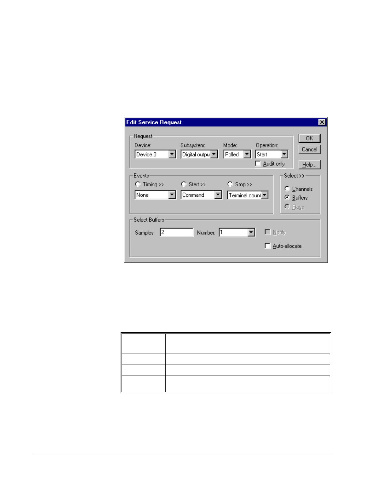
Digital Output Buffers
DriverLINX supports single-value, single-scan and buffered digital output.
• For single-value output, specify the Number of buffers as 0. The
buffer for a single value is the ioValue property.
• For single-scan output, specify the Number of buffer s as 1 and the
number of Samples equal to the number of channels.
How to set up the KPCI-3100 Series to store samples in buffers.
Digital Output Messages
For digital output operations, DriverLINX can report the fol lowing messages to the
application:
DriverLINX
Message
Service Start DriverLINX has started the acquisition task.
Service Done DriverLINX has completed the acquisition task.
Critical Error DriverLINX has encountered an unexpected hardware
Explanation
or software condition.
DriverLINX Event messages for digital output.
96 • Using the KPCI-3100 Series with DriverLINX Keithley KPCI-3100 Series
Page 97

For detailed explanations of these messages see one of the following references:
• DriverLINX Technical Reference Manual for C/C++ users
• DriverLINX/VB Technical Reference Manual for VB or Delphi users
Keithley KPCI-3100 Series Using the KPCI-3100 Series with DriverLINX • 97
Page 98

Counter/Timer Subsystem
The KPCI-3100 Series provides counter/timers for analog and digital input/output
pacing as well as independent counter/timer tasks. The KPCI-3100 Series uses the
same proprietary counter/timer chip as the KPCI-3140 Counter/Timer board. On the
KPCI-3100 Series, the chips counter/timers serve as dedicated pacer clocks, scan
clocks and general-purpose counter/timers.
All models have a 24-bit A/D clock to pace analog input. DriverLINX designates
this clock as Logical Channel 4. The analog input subsystem also has a 24-bit scan
clock. DriverLINX uses this clock in conjunction with the A/D clock when required
by the task. Models KPCI-3110 and 3116 have a 24-bit D/A clock to pace analog
output. DriverLINX designates this clock as Logical Channel 5.
The KPCI-3100 Series does not have a clock for digital input/output pacing.
Therefore, DriverLINX performs digital output in polled mode only. For digital
input, DriverLINX takes advantage of a feature that allows sampling Logical
Channels 0 and 1 with the A/D clock, as well as supporting digital input on all
channels in polled mode.
The KPCI-3100 Series also has external trigger and clock inputs for the analog input
and output, and digital input subsystems. See “Analog Input Subsystem Signals” on
page 29, “Analog Output Subsystem Signals” on page 30 or “Digital Input
Subsystem Signals” on page 31 for connection details.
All models have four 16-bit general-purpose counter/timers that support a wide
variety of counting and generation f unctions. DriverLINX d esignates these counters
as Logical Channels 0 through 3. Each counter/timer has a clock input, a gate input
and a counter output.
Model KPCI-3130
Logical
Channel
0 External Clock
An application specifies operating parameters for a counter/timer using a Rate Event
for the timing event in a service request. A Rate Event has clock source, mode and
gate properties. DriverLINX defines many useful generic c ounter/timer functions
that can be performed with most counter/timer chips. Alternatively, you can use
DriverLINX to program the board in specific modes of the proprietary, KPCI-3140
compatible, counter/timer chip. See the DriverLINX Counter/Timer User’s Guide for
detailed information on programming the KPCI-3140 counter/timer chip.
The following sections discuss usage of Rate Event properties for both input/output
task and counter/timer tasks.
DriverLINX
Function
(sample on DAC
overload)
KPCI-3130 Series External
Connector
+/- DAC Overload Sense Lines 0 … 7
Counter/Timer Channel Usage
The following table shows which Logical Channels are available for tasks on each
subsystem.
98 • Using the KPCI-3100 Series with DriverLINX Keithley KPCI-3100 Series
Page 99

Counter/Timer Logical Channel Usage
Counter/Timer Channel
Subsystem 0 1 2 3 4 5
Analog Input
Analog Output
Digital Input
Digital Output
Counter/Timer
For portability across drivers, applications can specif y the default timing channel
using the symbolic constant DEFAULTTIMER, rather than a specific channel
number.
Default
Default
Default
Default Available Available Available Available Available
Clock Sources and Modes
DriverLINX defines several internal and external clock sources and modes for Rate
Events on the KPCI-3100 Series. Some apply only to pacing certain subsystems.
Others are only for counter/timer tasks. The following tables lists the clock sources
and the modes to which they apply for use with each subsystem:
Analog Input
Name Source Modes
Internal 1 Internal 20 MHz RateGen
BurstGen
External
External+
External-
External
External-
External A/D TTL Trigger (major period)
Internal 20 MHz
(minor period)
External A/D Clock Input RateGen
BurstGen
Keithley KPCI-3100 Series Using the KPCI-3100 Series with DriverLINX • 99
Page 100

Analog Output
Name Source Modes
Internal 1 Internal 20 MHz RateGen
BurstGen
External
External+
External D/A TTL Trigger (major period)
Internal 20 MHz
(minor period)
BurstGen
ExternalExternal
External D/A Clock Input RateGen
External-
Digital Input
Name Source Modes
Internal 1 Internal 20 MHz RateGen
External
External-
Digital Output
The KPCI-3100 Series allows only untimed, polling of digital output channels.
External A/D Clock Input RateGen
Counter/Timer
Name
Internal 1 Internal 20 MHz RateGen
Exte rnal U ser Counter Input 0 D ivide r
Exte rnal+ User Counter Input 1 V DCGen
TCnm 1
*Logic al channels 1, 2 and 3 only
Source Modes
*
U ser Counter Input 2 SqWa ve
U ser Counter Input 3 Freq
OneShot
Freq32
Count
Count32
Count64
PulseWd
PulseGen
For portability across hardware with different drivers, app lications can use the
Sec2Tics function to determine the tic period of Internal 1.
100 • Using the KPCI-3100 Series with DriverLINX Keithley KPCI-3100 Series
 Loading...