

Page 1

Keithley KPCI-1800 Series
Using DriverLINX with Your
Hardware
Page 2

Information in this document is subject to change without notice. The software
described in this document is furnished under a license agreement. The software may
be used or copied only in accordance with the terms of the agreement.
SCIENTIFIC SOFTWARE TOOLS, INC. SHALL NOT BE LIABLE FOR ANY
SPECIAL, INCIDENTAL, OR CONSEQUENTIAL DAMAGES RELATED TO
THE USE OF THIS PRODUCT. THIS PRODUCT IS NOT DESIGNED WITH
COMPONENTS OF A LEVEL OF RELIABILITY SUITABLE FOR USE IN LIFE
SUPPORT OR CRITICAL APPLICATIONS.
This document may not, in whole or in part, be copied, photocopied, reproduced,
translated or reduced to any electronic medium or machine readable form without
prior written consent from Scientific Software Tools, Inc.
Keithley KPCI-1800 Series: Using DriverLINX with Your Hardware
Copyright 1999 by Scientific Software Tools, Inc.
All rights reserved.
First Printing.
SST 23-0399-3
DriverLINX, SSTNET, and LabOBJX are registered trademarks and
DriverLINX/VB is a trademark of Scientific Software Tools, Inc.
MetraByte is a trademark of Keithley Instruments, Inc.
Microsoft and Windows are registered trademarks and Visual C++ and Visual Basic
are trademarks of Microsoft Corporation.
Borland is a registered trademark and Borland C++ and Delphi are trademarks of
Borland International, Inc.
All other brand and product names are trademarks or registered trademarks of their
respective companies.
Page 3

Contents
Preface 5
Software License and Software Disclaimer of Warranty............................................................5
About DriverLINX.....................................................................................................................7
About This User’s Guide...........................................................................................................7
Conventions Used in This Manual.............................................................................................9
Configuring the KPCI-1800 Series 11
Introduction..............................................................................................................................11
Configure DriverLINX Device Dialog.....................................................................................11
Device Subsystem Page.............................................................................................13
Analog Input Subsystem Page ...................................................................................15
Analog Output Subsystem Page.................................................................................16
Digital Input Subsystem Page....................................................................................17
Digital Output Subsystem Page .................................................................................19
Counter/Timer Subsystem Page.................................................................................21
Using the KPCI-1800 Series with DriverLINX 23
Introduction..............................................................................................................................23
DriverLINX Hardware Model for KPCI-1800 Series..............................................................23
DriverLINX Subsystems............................................................................................23
DriverLINX Modes ...................................................................................................24
DriverLINX Operations and Events..........................................................................25
Logical Channels.......................................................................................................27
Buffers.......................................................................................................................27
Connecting Signals to the KPCI-1800 Series...........................................................................28
Analog Input Subsystem Signals................................................................................28
Analog Output Subsystem Signals.............................................................................29
Digital Input Subsystem Signals................................................................................29
Digital Output Subsystem Signals..............................................................................29
Counter/Timer Subsystem Signals.............................................................................30
Device Subsystem....................................................................................................................31
Device Modes............................................................................................................31
Device Operations .....................................................................................................31
Analog Input Subsystem ..........................................................................................................32
Analog Input Modes..................................................................................................32
Analog Input Operations............................................................................................32
Analog Input Timing Events......................................................................................33
Analog Input Start Events..........................................................................................41
Analog Input Stop Events..........................................................................................42
Analog Input Channels...............................................................................................45
Analog Input Buffers .................................................................................................49
Analog Input Data Coding.........................................................................................51
Keithley KPCI-1800 Series Contents • 3
Page 4

Analog Input Messages..............................................................................................52
Analog Output Subsystem........................................................................................................53
Analog Output Modes................................................................................................53
Analog Output Operations.........................................................................................53
Analog Output Timing Events...................................................................................54
Analog Output Start Events .......................................................................................57
Analog Output Stop Events........................................................................................58
Analog Output Channels............................................................................................59
Analog Output Buffers...............................................................................................62
Analog Output Data Coding ......................................................................................62
Analog Output Messages...........................................................................................63
Digital Input Subsystem...........................................................................................................64
Digital Input Modes...................................................................................................64
Digital Input Operations............................................................................................64
Digital Input Timing Events ......................................................................................64
Digital Input Start Events...........................................................................................69
Digital Input Stop Events...........................................................................................69
Digital Input Channels...............................................................................................70
Digital Input Buffers..................................................................................................72
Digital Input Messages..............................................................................................73
Digital Output Subsystem ........................................................................................................74
Digital Output Modes................................................................................................74
Digital Output Operations..........................................................................................74
Digital Output Timing Events ....................................................................................74
Digital Output Start Events........................................................................................77
Digital Output Stop Events........................................................................................77
Digital Output Channels.............................................................................................78
Digital Output Buffers...............................................................................................81
Digital Output Messages............................................................................................81
Counter/Timer Subsystem ........................................................................................................82
Gate Settings..............................................................................................................83
Uninstalling DriverLINX 85
How do I uninstall DriverLINX? .............................................................................................85
Troubleshooting 89
Solving Problems.....................................................................................................................89
Solving Problems Recognizing and Installing Drivers...............................................89
Solving Problems Configuring the Drivers................................................................91
Solving Problems Loading Drivers............................................................................91
Generating a DriverLINX Configuration Report .....................................................................94
What is in the Report? ...............................................................................................94
How do I Generate the Report?.................................................................................94
Glossary of Terms 95
Page 5

Preface
Software License and Software Disclaimer of Warranty
This is a legal document whic h is an agreement between you, the Licensee, and Scientific Software Tools, Inc. By opening this
sealed diskette package, Licensee agrees to bec ome bound by the terms of this Agreement, which include the S oftware License and
Software Disclaimer of Warranty.
This Agreement constit utes the complete Agreement between Licensee and Scient ific Software Tools, Inc. If Licensee does not
agree to the terms of this Agreement, do not open the dis kette package. Promptly return the unopened diskette package and the other
items (including written materials , binders or other containers, and hardware, if any) that are part of this product to S cientific Software
Tools, Inc. for a full refund. No ref unds will be given for products that have opened disk packages or missing components.
Licensing Agreement
Copyright. The software and doc umentation is owned by Scient ific Software Tools, Inc. and is prot ected by both United States
copyright laws and int ernational treaty provisions. Scient ific Software Tools, Inc. authoriz es the original purchaser only (Licensee) to
either (a) make one copy of t he software solely for backup or archival purposes, or (b) transf er the software to a si ngle hard disk only.
The written materials acc om panying the software may not be duplicated or copied for any reason.
Trade Secret. Licensee understands and agrees that the sof tware is the propriet ary and confident ial property of Scientifi c Software
Tools, Inc. and a valuable t rade secret. Li censee agrees to us e the software only for the intended us e under this License, and shall not
disclose the soft ware or i t s contents to any third part y.
Copy Restrictions. The Licensee may not modify or trans late the program or related documentation without the prior written
consent of Scientific Software Tools, Inc. All modifications, adapt ations, and me rged portions of the s oftware const itute the s oftware
licensed to t he Licensee, and the terms and conditions of this agreement apply to same. Licens ee may not distribut e copies, inc luding
electronic transfer of c opies, of the modif ied, adapted or m erged software or ac company ing written m aterials to others. Licensee agrees
not to reverse engineer, decompil e or di sassemble any part of the s of tware.
Unauthorized copying of the soft ware, including sof tware that has been m odified, merged, or i ncluded with other s oftware, or of t he
written materials is ex pressly forbidden. Licens ee may not rent, transfer or leas e the software to any third parties. Licens ee agrees to
take all reasonable steps to protect Scientific Software Tools’ software from theft, disclosure or use contrary to the terms of the License.
License. Scientific S oftware Tools, I nc. grants t he Licensee only a non-exclusiv e right to use the serialized copy of the software on
a single terminal connected t o a single computer. The Licens ee may not network the s oftware or use it on more t han one computer or
computer terminal at the s ame time.
Term. This Lic ense is effective until terminated. This License will terminate automatic ally without notice from Scientific Software
Tools, Inc. if Lic ensee fail s to com ply wit h any term or c ondition of this Licens e. The Licensee agrees upon such termination to ret urn or
destroy the written materi als and all copies of t he software. The Licensee may terminate the agreement by ret urning or destroying the
program and documentation and all copies thereof.
Keithley KPCI-1800 Series Preface • 5
Page 6

Limited Warranty
Scientific Software Tools, I nc. warrants that the software will perform subs tantially in acc ordance with the written mat erials and that
the program disk, instructi onal manuals and reference mat erials are free from defec ts in materials and workmanship under normal us e
for 90 days from the date of receipt. All express or im pl i ed warranties of the software and related materials are limited to 90 days.
Except as specif icall y set f orth herein, t he soft ware and accompany ing writt en materials (includi ng instruc tions f or use) are provided
“as is” without warranty of any kind. Further, Sc ientific Soft ware Tools, Inc. does not warrant , guarantee, or make any represe ntations
regarding the use, or the results of t he use, of the s of tware or writ ten mat erial s in terms of correct ness , acc uracy , reliabil ity, currentness,
or otherwise. The entire risk as to the results and perform ance of the software is as sumed by Licensee and not by Scienti fic Software
Tools, Inc. or its distributors, agents or employees.
EXCEPT AS SET F ORTH HE REI N, THE RE ARE NO OTHER WARRANT IE S, EI THER EXPRESS OR IMPLIED, INCLUDING BUT
NOT LIMITED TO IMPLIED WARRANTIES OF MERCHANTABILITY AND FITNESS FOR A PARTICULAR PURPOSE, WITH
RESPECT TO THE SOFTWARE, THE ACCOMPANYING WRITTEN MATERIALS, AND ANY ACCOMP ANYING HARDWARE.
Remedy. Scientific S oftware Tools’ ent ire liabilit y and the Licens ee’s ex clus ive remedy shall be, at Sc ientific Sof tware Tools’ opt ion,
either (a) return of the price paid or (b) repair or replac ement of the software or accompanying m aterials. In the event of a defect in
material or workmans hip, the item may be returned wit hin the warranty period to Scientific S oftware Tools for a replacement without
charge, provided the lic ensee previously s ent in the limited warrant y registration board t o Scientific Software Tools, I nc., or can furnis h
proof of the purchase of the program. This remedy is void if failure has resulted from accident, abuse, or misapplication. Any
replacement will be warranted for the remainder of the original warranty period.
NEITHER SCIENTIFIC SOFTWARE TOOLS, INC. NOR ANYONE ELSE WHO HAS BEEN INVOLVED IN THE CREATION,
PRODUCTION, SALE OR DELI VERY OF THIS PRODUCT S HALL BE LIABLE FOR ANY DIRE CT, INDIRECT, CONSEQUENTI AL,
OR INCIDENTAL DAMAGES (INCLUDING DAMAGES FOR LOSS OF BUSINESS PROFITS, BUSINESS INTERRUPTION, LOSS OF
BUSINESS INFORMATION AND THE LIKE) ARISING OUT OF T HE USE OF OR THE INABI LITY TO USE SUCH PRODUCT EVEN
IF SCIENTIFIC SOFTWARE TOOLS HAS BEEN ADVISED OF THE POSSIBILITY OF SUCH DAMAGES. BECAUSE SOME
JURISDICTIONS DO NOT ALLOW THE EXCLUSION OR LIMITATION OF LIABILITY FOR CONSEQUENTIAL OR INCIDENTAL
DAMAGES, OR LIMITATI ONS ON DURATION OF AN IMPLIED WARRANTY, THE ABOVE LIM ITATIONS MAY NOT APPLY TO
LICENSEE.
This agreement is governed by the laws of the Commonwealth of Pennsylvania.
6 • Preface Keithley KPCI-1800 Series
Page 7

About DriverLINX
Welcome to DriverLINX for Microsoft Windows, the high-performance realtime data-acquisition device drivers for Windows application development.
DriverLINX is a language- and hardware-indepe ndent applic ation programming
interface designed to support hardware manufacturers’ high-speed analog, digital,
and counter/timer data-acquisition boards in Windows. DriverLINX is a multi-user
and multitasking data-acquisition resource manager providing more than 100 services
for foreground and background data acquisition tasks.
Included with your DriverLINX package are the following items:
• The DriverLINX API DLLs and drivers supporting your data-
acquisition hardware
• Analog I/O Panel, a DriverLINX program that verifies the installation
and configuration of DriverLINX for your analog input/output board
and demonstrates several virtual bench-top instruments
• Learn DriverLINX, an interactive learning and demonstration program
for DriverLINX that includes a Digital Storage Oscilloscope
• Source code for the sample programs
• The DriverLINX Application Programming Interface files for your
compiler
• DriverLINX On-line Help System
• DriverLINX 4.0 Installation and Configuration Guide
• DriverLINX Analog I/O Programming Guide
• DriverLINX Technical Reference Manual
• Supplemental Documentation on DriverLINX and your data-acquisition
hardware
About This User’s Guide
The purpose of this manual is to help you quickly learn how to configure and use t he
hardware features of Keithley’s KPCI-1800 Series boards with DriverLINX.
• For help installing and configuring your hardware and Dr iverLINX,
please see the manual that accompanied your hardware and the
DriverLINX 4.0 Installation and Configuration Guide for your version
of Windows.
• For more information on the DriverLINX API, please see the
DriverLINX Technical Reference Manual.
• For additional help programming your board, please examine the source
code examples on the Distribution Disks.
This manual contains the following chapters:
Configuring the KPCI-1800 Series
Shows how to configure the KPCI-1800 Series using the Configure DriverLINX
Device dialog box.
Keithley KPCI-1800 Series Preface • 7
Page 8

Using the KPCI-1800 Series with DriverLINX
Shows how to set up DriverLINX with the Edit Service Request dialog box to use
KPCI-1800 Series hardware features.
Uninstalling DriverLINX
Describes how to remove DriverLINX hardware drivers and other files.
Troubleshooting
Gives troubleshooting tips for installing, configur ing, and loading D riverLINX
drivers.
8 • Preface Keithley KPCI-1800 Series
Page 9

Conventions Used in This Manual
The following notational conventions are used in this manual:
• A round bullet (•) identifies itemized lists.
• Numbered lists indicate a step-by-step procedure.
• DriverLINX Application Programming Interface and Windows macro
and function names are set in bold when mentioned in the text.
• DriverLINX indicates the exported function name of the device driver
DLL while DriverLINX indicates the product as a whole.
• DriverLINX Application Programming Interface identifiers, menu
items, and Dialog Box names are italicized when mentioned in the text.
• Italics are used for emphasis.
• Source code and data structure examples are displayed in Courier
typeface and bounded by a box with a single line.
Code
• A box with a double line bound tables of information.
Concept
Tables
• Important concepts and notes are printed in the left margin.
Keithley KPCI-1800 Series Preface • 9
Page 10

Page 11

Configuring the KPCI-1800 Series
Introduction
The installation program provides general instructions for installing and configuring
DriverLINX. This manual explains the steps and special features that apply to
Keithley’s KPCI-1800 Series boards.
Windows NT
Installing and configuring DriverLINX for a Keithley KPCI-1800 Series board
requires three steps:
1. Install DriverLINX. Follow the instructions given by the installation
program. The Read Me First instructions explain the components and
drivers you can install.
2. Configure DriverLINX. This creates a Logical Device, which stores
configuration information for your board. See “Configure Dri verLINX
Device Dialog” on page 11 for configuration options specific to a
Keithley KPCI-1800 Series model.
3. Install your KPCI-1800 hardware, read and follow the instructions in
your hardware manual.
After configuring DriverLINX, instal l ing your board and restarting Windows, reopen
the DriverLINX Configuration Panel to make sure that DriverLINX loaded the
Logical Device for your board. If the Logical Device is not loaded, the Event Log
may have a message from the driver that explains why. You can check the Event Log
using the DriverLINX Event Viewer on the Windows Start Menu.
Under Windows NT 4.0, a Logical Device may not load because the operating
system does not always configure Plug-and-Play PCI devices properly. To work
around this, set your computer’s BIOS to configure Plug-and-Play devi ces before it
starts the operating system. On various computers the BIOS setting is called “Plugand-Play Aware OS – Disabled” or “Plug & Play OS – No”.
Configure DriverLINX Device Dialog
DriverLINX uses a standardized configuration protocol for all data-acquisition
hardware. Configur ation assigns an identi fying device number to a specific KPCI1800 Series board in your computer and allows you to enable or disable bus
mastering.
Keithley KPCI-1800 Series Configuring the KPCI-1800 Series • 11
Page 12

The installation program automatically starts the DriverLINX Configuration Panel.
To start it now, use the shortcut on the Windows Start Menu or click here
.
When you click the Configure… button on the DriverLINX Configuration Panel,
DriverLINX displays the Configure DriverLINX Device dialog. The dialog has a
page for each subsystem on the Keithley KPCI-1800 Series. The following sections
describe your choices in configuring DriverLINX to work with your board.
12 • Configuring the KPCI-1800 Series Keithley KPCI-1800 Series
Page 13

Device Subsystem Page
Use the Device subsystem page to tell DriverLINX the model name of your KPCI1800 Series board.
Vendor
Windows NT
Windows 95/98
The Vendor property displays “Keithley Instruments, Inc.” It is a read-only property.
Device
The Device property designates the Logical Device you are configuring. It is a readonly property. To change it, first save (OK) or quit (Cancel) the current
configuration. Then select or create a new Logical Device using the DriverLINX
Configuration Panel.
Model
The Model property selects or indicates the hardware model of the board you’re
configuring.
Select one of the following models:
KPCI-1801HC
KPCI-1802HC
Windows 95 automatically determines the model of your board so DriverLINX
disables Model selection.
Board Id
The Board Id property associates this Logical Device with a specific board.
DriverLINX automatically enters the KPCI-1800’s serial number in this field.
DriverLINX use s the board’s ser ial number to uniquely recognize boards if you have
installed multiple boards of the same model into your computer.
Windows NT
Keithley KPCI-1800 Series Configuring the KPCI-1800 Series • 13
Under Windows NT, Board Id is initially blank. DriverLINX will use the Model
setting to match this Logical Device to the first available board and then enter that
board’s serial number.
Page 14

Windows 95/98
Windows 95/98 automatically determines which board to associate with this Logical
Device. DriverLINX enters the serial number of the board when it starts the
configuration.
Detect
The Detect property enables and disables DriverLINX’s hardware detection and
testing algorithms. For maximum system reliability, always leave this check-box
marked.
Calibrate
The Calibrate property enables and disables hardware auto-calibration. This option is
grayed-out for the KPCI-1800 Series because it does not support automatic
calibration.
Special…
The Special… button displays the following dialog box of KPCI-1800 Series-specific
configuration options:
Bus Mastering
Bus Mastering is a mode that PCI devices use to perform DMA data transfers. The
KPCI-1800 Series can use bus mastering on motherboards that support it. With bus
mastering disabled, the board will operate in interrupt mode when the Service
Request asks for DMA mode. For maximum throughput, enable bus mastering if your
motherboard supports it.
Motherboards compliant with revision 2.1 of the PCI specification support bus
mastering. Almost all newer motherboards support bus mastering but some require
BIOS settings to enable it for a particular PCI slot. Older motherboards may not
support bus mastering at all and may cause the system to hang, risking loss of
unwritten disk data and requiring you to reboot. Consult your computer
manufacturer’s documentation to determine if your motherboard supports bus
mastering.
To test bus-mastering, check the Enable Bus Mastering box, click OK as necessary to
exit the DriverLINX Configuration Panel and restart Windows. Close all other
applications, wait until all disk activity stops, then run the DriverLINX AIO Panel. If
the AIO Panel can display an input signal then your motherboard is compatible with
your KPCI-1800 board. As long as your BIOS has enabled bus-mastering for the PCI
slot your board is in, DriverLINX can use DMA mode.
14 • Configuring the KPCI-1800 Series Keithley KPCI-1800 Series
Page 15

Analog Input Subsystem Page
Use the Analog Input subsystem page to choose between 64 single-ended or 32
differential analog input channels as a default configuration.
Channels
On the KPCI-1800 Series, each Analog Input channel can use single-ended or
differential connections. When configuring the Analog Input Subsystem, you choose
a default configuration for all channels. Applications can use the default
configuration or specify the connection type for each channel it uses. This scheme
supports applications that use KPCI-1800-specific features as well as those that use
only generic features. For programming information, see “Anal og Input Channels” on
page 45.
Range
The analog input ranges for the KPCI-1800 Series are fully software programmable.
DriverLINX grays out this property in the configuration dialog.
Interrupt
Windows automatically determines the interrupt level for the KPCI-1800 board.
DriverLINX disables this property.
DMA
The KPCI-1800 Series does not use DMA channels for direct memory transfers. PCI
devices use bus mastering for DMA. DriverLINX initially disables bus mastering for
your KPCI-1800 board. See “Special…” on page 14 for more information.
Keithley KPCI-1800 Series Configuring the KPCI-1800 Series • 15
Page 16

Analog Output Subsystem Page
Use the Analog Output subsystem page to set or view the initial output voltages.
Channels
Lists the analog output channels on the board and selects a channel for the Volts and
Initialize properties.
Range
The analog output ranges for the KPCI-1800 Series are fully software programmable.
DriverLINX grays out this property in the configuration dialog.
Volts
The Initialization Value property specifies the analog output value DriverLINX will
write to the selected Logical Channel upon hardware initialization. DriverLINX only
writes this value if you enable the In
itialize check box.
Interrupt
Windows automatically determines the interrupt level for the KPIC-1800 board.
DriverLINX disables this property.
DMA
The KPCI-1800 Series does not use DMA channels for direct memory transfers.
DriverLINX disables this property.
Initialize
Checking the Initialize check box instructs DriverLINX to use the Volts property for
analog output initialization.
16 • Configuring the KPCI-1800 Series Keithley KPCI-1800 Series
Page 17

For the KPCI-1800 Series,
there are no configurable
options on the Digital Input
subsystem page.
Digital Input Subsystem Page
Channels
The Channels property allows you to select a Logical Channel for configuration or
viewing the channel’s range. The KPCI-1800 Series digital channels have fixed
configurations.
DriverLINX defines the following Logical Channels for the KPCI-1800 Series digital
inputs:
Logical
Channel
0 Standard Digital Input DI 0 … DI 3
1 External Clock XPCLK
2 External Trigger TGIN
DriverLINX Function KPCI-1800 Series
External Connector
Range
The Range property specifies the supported digital input range for the selected
Logical Channel. This is a read-only property.
Interrupt
The KPCI-1800 Series does not use interrupts for the digital input subsystem.
DriverLINX disables this property and displays it as blank.
DMA
The KPCI-1800 Series does not use DMA channels for direct memory transfers.
DriverLINX disables this property.
Configuration Setup
The Configuration Setup property specifies the hardware configuration of the digital
I/O ports. The KPCI-1800 Series has a fixed digital I/O configuration. Therefore,
DriverLINX disables this field.
Keithley KPCI-1800 Series Configuring the KPCI-1800 Series • 17
Page 18

Initialize
Checking the Initialize check box instructs DriverLINX to use the Configuration
S
etup property to configure the digital I/O ports. The KPCI-1800 Series has a fixed
digital I/O configuration. Therefore, DriverLINX disables this field.
18 • Configuring the KPCI-1800 Series Keithley KPCI-1800 Series
Page 19

Digital Output Subsystem Page
Use the Digital Output subsystem page to change the default digital output port
initialization values.
Channels
The Channels property allows you to select a Logical Channel for initialization or
viewing the channel’s range . DriverLINX defines the follo wing Logical Channels for
the KPCI-1800 Series digital outputs:
Logical
Channel
0 Standard Digital Output DO 0 … DO 7
DriverLINX Function KPCI-1800 Series
External Connector
Range
The Range property specifies the supported digital output range for the selected
Logical Channel. This is a read-only property.
Interrupt
The KPCI-1800 Series does not use interrupts for the digital output subsystem.
DriverLINX disables this property and displays it as blank.
DMA
The KPCI-1800 Series does not use DMA channels for direct memory transfers.
DriverLINX disables this property.
Initialization Value
The Initialization Value property specifies the digital output value DriverLINX will
write to the selected Logical Channel upon hardware initialization. DriverLINX only
writes this value if you enable the In
Keithley KPCI-1800 Series Configuring the KPCI-1800 Series • 19
itialize check box.
Page 20

Initialize
Checking the Initialize check box instructs DriverLINX to use the Initialization
V
alue property for digital output port initialization.
Dec
This check box converts the Initialization Value property to decimal.
Hex
This check box converts the Initialization Value property to hexadecimal.
20 • Configuring the KPCI-1800 Series Keithley KPCI-1800 Series
Page 21

Counter/Timer Subsystem Page
Resolution
The Resolution property specifies the default clock frequency of the master
oscillator. All models have a programmable 10 MHz, 5 MHz, 1 MHz or 100 kHz
clock source for pacing input/output tasks. This setting selects the default frequency.
Applications can use the default or specify a frequency for each task.
Interrupt
Windows automatically determines the interrupt level for the KPCI-1800 board.
DriverLINX disables this property.
Keithley KPCI-1800 Series Configuring the KPCI-1800 Series • 21
Page 22

Page 23

Using the KPCI-1800 Series with
DriverLINX
Introduction
See the Analog I /O
Programming Guide for an
overview of DriverLINX
programming.
This chapter shows you how to set up and use KPCI-1800 Series hardware features
with DriverLINX.
The descriptions here use the Edit Service Request dialog for language and API
independence. For the corr ect syntax with the language you’re using, p lease see the
DriverLINX Technical Reference Manuals. For DriverLINX examples in your
programming language, p lease see the sourc e code examples in the subdirectories of
your DriverLINX installation directory or on the original distribution media.
DriverLINX Hardware Model for KPCI-1800 Series
DriverLINX provides a portable, hardware-independent API for data-acquisition
boards while still allowing applications to access unique or proprietary hardware
features of specific products. To achieve this goal, DriverLINX maps a hardwareindependent, or abstract, data-acquisition model onto KPCI-1800 Series hardware
capabilities.
The following sections describe how DriverLINX implements KPCI-1800 Series
hardware features as Subsystems, Modes, Operations, Events, Logical Channels,
Buffers, and Messages.
DriverLINX Subsystems
The KPCI-1800 Series supports the following DriverLINX subsystems:
1. Device—refers to a KPCI-1800 board as a whole.
2. Analog Input—refers to the analog input channels, clocks, and control
signals.
3. Analog Output—refers to the analog output channels, clocks, and
control signals.
4. Digital Input—refers to the digital input port as well as 1-bit digital
input (TTL) control signals, such as TGIN.
Keithley KPCI-1800 Series Using the KPCI-1800 Series with DriverLINX • 23
Page 24

5. Digital Output—refers to the digital output port.
6. Counter/Timer—refers to the input/output subsystem-specific internal
clock channels for pacing analog input/output.
DriverLINX Modes
Applications use modes in Service Requests to advise DriverLINX on their preferred
hardware data transfer technique. The DriverLINX modes fall into two general
classes:
• Foreground or synchronous modes. The calling application doesn’t
regain control until DriverLINX completes the Service Request.
DriverLINX supports this mode for simple, single value I/O operations
or software housekeeping functions that DriverLINX can complete
without a significant delay.
• Background or asynchronous modes. The calling application regains
control as soon as DriverLINX initiates the task. The calling application
must synchronize with the data-acquisition task using status polling or
DriverLINX’s messages (preferred). DriverLINX supports this mode
for buffered data transfers or for commands that require a significant
time to complete.
DriverLINX supports four modes with the KPCI-1800 Series for its commands
(Service Requests).
• Polled Mode—This is a foreground or synchronous op eration.
DriverLINX supports this mode for simple, single-value I/O operations
that the data-acquisition board can complete without significant delay.
• Interrupt Mode—T his is a background or asynchronous op eration.
DriverLINX transfers data between the computer’s memory and the
data-acquisition board using hardware interrupts and programmed I/O
transfers.
• DMA Mode—This is a backgro und or asynchronous o peration.
DriverLINX programs the data-acquisition board to transfer data
between the computer’s memory and the board.
• Other Mode—This i s a foreground or synchronous operation.
DriverLINX supports this mode for initialization, configuration,
calibration, data conversion, and timebase operations.
24 • Using the KPCI-1800 Series with DriverLINX Keithley KPCI-1800 Series
Page 25

The following table summarizes the data acquisition modes that DriverLINX
supports for each subsystem with the Keithley KPCI-1800 Series.
Subsystem Polled Interrupt DMA Other
Analog Input
Analog Ou tput
Digital Input
Digital Output
Counter/Timer
Device
√ √ √ √
√ √ √ √
√ √
√ √
KPCI-1800 Series Supported DriverLINX Modes.
√
√
√
√
DriverLINX Operations and Events
Applications construct DriverLINX data-acquisition tasks by combining a small
number of DriverLINX operations and events in many possible ways. The following
table summarizes the operations and events that DriverLINX supports for the
Keithley KPCI-1800 Series. Later sections for each DriverLINX subsystem will
describe the operations and events in more detail.
Keithley KPCI-1800 Series Using the KPCI-1800 Series with DriverLINX • 25
Page 26

Note: All subsystems allow the MESSAGE operation and the Analog Input
subsystem allows the CONVERT operation, which are not shown in the table.
DriverLINX allows any Mode setting for these operations.
Subsystem Operation Events
Mode Timing Start Stop
Analog Input
Polled Start null null, cmd null, TC
Interrupt Start, Stop,
Status
DMA Start, Stop,
Status
Other Initialize
Analog Output
Polled Start null null, cmd null, TC
Interrupt Start, Stop,
Status
DMA Start, Stop,
Status
Other Initialize
dig, rate cmd, dig cmd, TC, dig
dig, rate cmd, dig cmd, TC, dig
rate cmd, dig cmd, TC
rate cmd, dig cmd, TC
Digital Input
Polled Start null null, cmd null, TC
Interrupt Start, Stop,
rate cmd cmd, TC
Status
Other Initialize
Digital Output
Polled Start null null, cmd null, TC
Interrupt Start, Stop,
rate cmd cmd, TC
Status
Other Initialize
Counter/Timer
Other Initialize
Device
Other Initialize,
Configure,
Capabilities
Allowed Operations and Events for KPCI-1800 Series Subsystems and Modes.
26 • Using the KPCI-1800 Series with DriverLINX Keithley KPCI-1800 Series
Page 27

The following list explains the Event abbreviations in the preceding table:
• null—Null or None Event when a Service Request doesn’t require an
event
• cmd—Command Event when DriverLINX starts or stops a task on
software command
• TC—Terminal Count Event when DriverLINX processes all data
buffers once
• rate—Rate Event specifies how DriverLINX paces or clocks data
transfer
• dig—Digital Event specifies a trigger, clock, or other control signal to
pace, start, or stop a task
Logical Channels
DriverLINX designates the individually addressable hardware channels for each
subsystem as “Logical Channels.” Generally, the zero-based Logical Channel
numbering sequence closely follows the hardware manufacturer’s cha nnel numbering
scheme.
In some cases, however, DriverLINX assigns Logical Channel numbers to hardware
features that users don’t commonly think of as “channels.” For instance, DriverLINX
commonly models external hardware clock input lines, external hardware trigger
input lines, and external interrupt inputs as 1-bit digital Logical Channels. In other
cases, DriverLINX models subsystem-specific features, such as internal pacer clocks,
as members of a more general-purpose set of counter/timer channels.
For a list of DriverLINX assigned Logical Channel numbers, see the notes on each
supported subsystem.
Buffers
Applications usually use data buffers to exchange data between the application and
the data-acquisition hardware. When using data buffers, please note the following
points about DriverLINX’s data buffers:
• DriverLINX supports data-acquisition tasks with 1 to 255 data buffers
per task.
• DriverLINX imposes no size limits on a single buffer, although the
operating system or some hardware products may have size restrictions.
• User applications must allow DriverLINX to allocate all data buffers to
guarantee application portability to different hardware and operating
systems and to insure that the hardware can physically access the buffer
memory.
• User applications usually don’t have concurrent or immediate access to
the in-use data buffer while DriverLINX is executing a data-acquisition
task.
Keithley KPCI-1800 Series Using the KPCI-1800 Series with DriverLINX • 27
Page 28

Connecting Signals to the KPCI-1800 Series
The Keithley hardware manual describes the data and control signals for the KPCI1800 Series and the connector pinouts for these signals. This section summarizes how
DriverLINX numbers the I/O data signals and how DriverLINX uses the control
connections for external clock, trigger, a nd gating inputs.
Analog Input Subsystem Signals
The Analog Input subsystem has 64 analog inputs and an analog ground. You set the
default subsystem configuration as 32 differential or 64 single-ended channels.
Applications can then use the default configuration or request a specific configuration
for each channel. See “Analog Input Channels” on page 45 for programming
information.
DriverLINX maps these connections to Logical Channels as shown in the following
table:
Physical Channels Connector Name Logical
Channels
0 – 31 Differential CH00LO, HI – CH31LO, HI 0 – 31
0 – 63 Single-ended CH00LO – CH63LO, AGND 0 – 63
How DriverLINX maps analog input hardware channels to Logical Channels.
Analog Input Pacing, Trigger ing and Gating Signals
Analog input tasks can use the input-pacing counter, which DriverLINX designates
as Counter/Timer Logical Channel 0. For this counter the clock source can be
internal or external.
The Analog Input subsystem uses two control signals that DriverLINX defines as an
external clock and a trigger/gate as shown in the following table:
Connector Name DriverLINX Usage
TGIN External trigger/gate
XPCLK External pacer clock
How DriverLINX uses analog i nput control signals.
28 • Using the KPCI-1800 Series with DriverLINX Keithley KPCI-1800 Series
Page 29

Analog Output Subsystem Signals
The Analog Output subsystem has 2 analog differential output connections.
DriverLINX maps these connections to Logical Channels as shown in the following
table:
Physical
Channel
0 DAC0IN,DAC0OUT 0
1 DAC1IN, DAC1OUT 1
How DriverLINX maps analog output hardware channels to Logical Channels.
Connector Name Logical
Channel
Digital Input Subsystem Signals
The Digital Input subsystem has one 4-bit digital input port and two control inputs
which DriverLINX models as 1-bit logical digital input ports. DriverLINX maps
these signals to Logical Channels as shown in the following table:
Port Connector Name Logical Channel
4-bit digital input DI 0 … DI 3 0
External clock alias XPCLK 1
External trigger alias TGIN 2
How DriverLINX maps digital input hardware channels to Logical Channel s.
Digital Output Subsystem Signals
The Digital Output subsystem has an 8-bit digital output port. DriverLINX maps
these signals to Logical Channels as shown in the following tables:
Port Connector Name Logical Channel
8-bit digital output DO 0 … DO 7 0
How DriverLINX maps digital output hardware channels to Logical Channel s.
Keithley KPCI-1800 Series Using the KPCI-1800 Series with DriverLINX • 29
Page 30

Counter/Timer Subsystem Signals
The Counter/Timer subsystem has an external clock source and a gate input that the
board can use with any Logical Channel. DriverLINX maps these signals as shown in
the following table:
8254 Chip Counter Connector Name Logical Channel
Counters 1 & 2 XPCLK, TGIN 0
Counter 0 XPCLK, TGIN 1
Counter 1 XPCLK, TGIN 2
Counter 2 XPCLK, TGIN 3
How DriverLINX maps counter/ timer hardware channels to Logical Channels .
30 • Using the KPCI-1800 Series with DriverLINX Keithley KPCI-1800 Series
Page 31

f
Device Subsystem
The following sections describe how DriverLINX implements Device Subsystem
features for the KPCI-1800 Series.
Device Modes
The Device Subsystem supports only DriverLINX’s Other mode for all operations.
Device Operations
The KPCI-1800 Series Device Subsystem supports the following DriverLINX
operations:
If another application is using
the same data-acquisition
board, DriverLINX will
prevent Device Initialization
rom interfering with another
application’s data-acquisition
tasks.
• Initialize—DriverLINX aborts all data-acquisition tasks for every
subsystem controlled by the current application. DriverLINX then
initializes each subsystem.
• Configure—DriverLINX displays the Configure DriverLINX Device
dialog for the current Logical Device. Please use the DriverLINX
Configuration Panel rather than this operation to configure
DriverLINX.
• Capabilities—DriverLINX provides hardware-specific and
configuration information in the form of a Logical Device Descriptor
database.
Keithley KPCI-1800 Series Using the KPCI-1800 Series with DriverLINX • 31
Page 32

Analog Input Subsystem
The following sections describe how DriverLINX implements Analog Input
Subsystem features for the KPCI-1800 Series.
Analog Input Modes
The Analog Input Subsystem supports the following modes:
• Polled—For single-value or scan analog-input samples.
• Interrupt—For buffered transfers using programmed I/O.
• DMA—For buffered transfers using direct memory access.
• Other—For subsystem initialization and data conversion.
Analog Input Operations
The KPCI-1800 Series Analog Input Subsystem supports the following DriverLINX
operations:
• Initialize—aborts all active analog input data-acquisition tasks.
However, DriverLINX prevents one application from interfering with
another application’s data-acquisition tasks.
• Start—initiates a data-acquisition task using the Mode, Timing, Start,
and Stop Events, the Logical Channels, and the Buffers the application
specified in the Service Request.
• Status—reports the buffer position of the next sample that DriverLINX
will write into a buffer.
• Stop—terminates an analog input data-acquisition task.
• Message—DriverLINX displays a pop-up dialog box for the user
containing the text for the current DriverLINX error message.
32 • Using the KPCI-1800 Series with DriverLINX Keithley KPCI-1800 Series
Page 33

Analog Input Timing Events
Timing Events specify how the hardware paces or clocks the acquisition of analog
input samples. DriverLINX uses the Timing Event to program when the KPCI-1800
Series acquires the next analog input sample.
The KPCI-1800 Series supports the following Timing Events:
• None—Sampling requires no pacing as DriverLINX is acquiring only a
single value or scan.
• Rate—The KPCI-1800 Series supports fixed rate and burst mode
sampling using internal and external clocks.
• Digital—DriverLINX uses an external digital input signal to pace the
acquisition of the next sample.
None or Null Event
The Null Event specifies that the task does not need a clock to determine when to
acquire the next sample.
Rate Event
The KPCI-1800 Series supports two types of Rate Events for analog input:
• Rate Generator—Generates a fixed rate clock with equal time
intervals between tics.
• Burst Generator—Generates a dual frequency clock with a fixed
number of tics at a high frequency separated by a time interval at a
lower frequenc y.
KPCI-1800 boards have a programmable 10 MHz, 5 MHz, 1 MHz or 100 kHz
master clock frequency. The sample period can range from 3 µs to
kHz. This means the sample rate can range from 0.0000233 Hz to 333kHz. However,
using multiple channels or non-unity gains may reduce the maximum sample rate.
Consult your hardware manua l for details.
32
21
− tics at 100
Keithley KPCI-1800 Series Using the KPCI-1800 Series with DriverLINX • 33
Page 34

Rate Generator: Internal Clocking
An internally clocked Rate Generator produces a fixed rate clock with equal time
intervals between tics.
Period
Use an internally clocked rate generator when you want to acquire all analog input
samples at equally spaced time intervals.
How to set up the KPCI-1800 Series for fixed rate sampling us i ng an i nternal clock.
For hardware independence,
specify the clock channel
using the symbolic constant,
DEFAULTTIMER, which
always maps to the default
Logical Channel for analog
input timing.
• Specify internal clocking using a Rate Generator on any available
Channel with any internal Clock source. See “Counter/Timer
Subsystem” on page 82 for a description of clock sources.
• The Period property specifies the time interval between samples in tics,
where a tic period depends on the clock source. The minimum period is
3 µs. The maximum period is 4294967295 tics (
or 65535 tics (
) for the other channels. See “Counter/Timer
1216−
32
21
− ) for Channel 0
Subsystem” on page 82 for details.
• The Gate property specifies how the TGIN signal affects the operation
of the internal clock. Valid settings are Enabled, Disabled, and Hi
Level, Low Level, Low Edge and High Edge Enabled. See
“Counter/Timer Subsystem” on page 82 for a description of each Gate
setting.
Note: You cannot use a gated clock with a digital start or stop trigger.
34 • Using the KPCI-1800 Series with DriverLINX Keithley KPCI-1800 Series
Page 35

Rate Generator: External Clocki ng
An externally clocke d Rate Generator produces a rate clock with unknown time
intervals between tics.
Period (ext clk)
Use an externally clocked rate generator when you want to synchronize analog input
samples with a recurrent external signal. In this mode you will need a separate
external clock tic for each analog sample you want to acquire.
Be sure that the external
clock source is TTL
compatible, 0 V minimum to
+5 V maximum!
How to set up the KPCI-1800 Series for fixed rate sampling us i ng an external clock.
• Specify external clocking using a Rate Generator on any available
Channel with an External, External+, or External- Clock source.
See “Counter/Timer Subsystem” on page 82 for a description of clock
sources. For hardware-independence, you can specify the hardware
external clock channel by the symbolic constant, DI_EXTCLK.
• Users should connect the external clock signal to the XPCLK line.
• The Period may be any value ≥ 3 µs. The period value doesn’t affect
the external clock frequency, but DriverLINX requires a valid hardware
value in case the application requests a timebase operation and to
optimize data transfer between the driver and the application. Period is
in tics, where a tic period depends on the clock source. See
“Counter/Timer Subsystem” on page 82 for details.
• The frequency of the external clock must not exceed 333 kHz.
• The Gate property specifies how the TGIN signal affects the operation
of the internal clock. Valid settings are Enabled, Disabled, and Hi
Level, Low Level, Low Edge and High Edge Enabled. See
“Counter/Timer Subsystem” on page 82 for a description of each Gate
Keithley KPCI-1800 Series Using the KPCI-1800 Series with DriverLINX • 35
Page 36

setting.
Note: You cannot use a gated clock with a digital start or stop trigger.
36 • Using the KPCI-1800 Series with DriverLINX Keithley KPCI-1800 Series
Page 37

Burst Generator: Internal Clocking
An internally clocked Burst Generator produces a dual frequency clock with a fixed
number of tics at a high frequency repeated at a lower frequency.
Use an internally clocked rate generator when you want to acquire analog input
samples from a several channels at closely spaced time intervals and then repeat at
longer intervals.
How to set up the KPCI-1800 Series for burst mode sampling using an int ernal clock.
For hardware independence,
specify the clock channel
using the symbolic constant,
DEFAULTTIMER, which
always maps to the default
Logical Channel for analog
input timing.
• Specify internal clocking using a Burst Generator on any available
Channel with any internal Clock source. For hardware independence,
specify the clock channel using the symbolic constant,
DEFAULTTIMER, which always maps to the default Logical Channel
for analog input timing. See “Counter/Timer Subsystem” on page 82
for a description of clock sources.
• The Period property specifies the time interval between the start of
each burst in tics, where a tic period depends on the clock source. The
minimum period is 3 µs. The maximum period is 4294967295 tics
32
(
21
− ) for Channel 0 or 65535 tics (
) for the other channels.
1216−
See “Counter/Timer Subsystem” on page 82 for details.
• The On time property specifies the time interval between samples. It
×
must be within the range of 4µs to 64µs. Also Pulses
(On time + 1µs)
must be less than Period.
Keithley KPCI-1800 Series Using the KPCI-1800 Series with DriverLINX • 37
Page 38

• The Gate property specifies how the TGIN signal affects the operation
of the internal clock. Valid settings are Enabled, Disabled, and Hi
Level, Low Level, Low Edge and High Edge Enabled. See
“Counter/Timer Subsystem” on page 82 for a description of each Gate
setting.
Note: You cannot use a gated clock with a digital start or stop trigger.
• The Pulses property specifies how many channels the board samples in
each Period. Pulses must equal the number of channels in the channel
list.
Burst Generator: External Clocking
An externally clocked Rate Generator produces a dual frequency clock with a fixed
number of tics at a high, internal frequency repeated at a lower, externally controlled
frequency.
Use an externally clocked burst generator when you want to synchronize a burst of
analog input samples with a recurrent external signal. In this mode you will need a
separate external clock tic for each burst of analog samples you want to acquire.
How to set up the KPCI-1800 Series for burst mode sampling using an external clock.
38 • Using the KPCI-1800 Series with DriverLINX Keithley KPCI-1800 Series
Page 39

BE SURE that the external
clock source is TTL
compatible, 0 V minimum to
+5 V maximum!
• Specify external clocking using a Burst Generator on any available
Channel with an External, External+, or External- Clock source.
See “Counter/Timer Subsystem” on page 82 for a description of clock
sources. For hardware-independence, you can specify the hardware
external clock channel by the symbolic constant, DI_EXTCLK.
• Users should connect the external clock signal to the XPCLK line.
• The Period may be any value ≥ 3 µs. The period value doesn’t affect
the external clock frequency, but DriverLINX requires a valid hardware
value in case the application requests a timebase operation and to
optimize data transfer between the driver and the application. Period is
in tics, where a tic period depends on the clock source. See
“Counter/Timer Subsystem” on page 82 for details.
• The On time property specifies the time interval between samples. It
must be within the range of 4µs to 64µs. Also Pulses
×
(On time + 1µs)
must be less than Period.
• The frequency of the external clock must not exceed 333 kHz.
• The Gate property specifies how the TGIN signal affects the operation
of the internal clock. Valid settings are Enabled, Disabled, and Hi
Level, Low Level, Low Edge and High Edge Enabled. See
“Counter/Timer Subsystem” on page 82 for a description of each Gate
setting.
Note: You cannot use a gated clock with a digital start or stop trigger.
• The Pulses property specifies how many channels the board samples in
each Period. Pulses must be between 2 and the number of channels in
the channel list.
Keithley KPCI-1800 Series Using the KPCI-1800 Series with DriverLINX • 39
Page 40

Digital Event
DriverLINX supports Digital Events as aliases for externally clocked Rate
Generators. Use this technique for compatibility with data-acquisition products that
only support external clock sources.
How to set up the KPCI-1800 S eri es for external rate sampling using a di gi t al event.
• Specify external cl ocking using Channel 1. For hardwareindependence, you can specify the hardware external trigger channel by
the symbolic constant, DI_EXTCLK.
• Users should connect the external clock signal to the XPCLK line.
• Specify the Mask property as 1, or Bit 0, to indicate that DriverLINX
should only compare a 1-bit digital input value against the Pattern
property.
• Specify the Match property as N
ot equals.
• Specify the Pattern property as 0 for a rising, or positive, edge clock
(≠0) or 1 for a fal ling, or negative , edge clock (≠1).
40 • Using the KPCI-1800 Series with DriverLINX Keithley KPCI-1800 Series
Page 41

Analog Input Start Events
Start Events specify when the KPCI-1800 hardware starts acquiring analog input
data.
The KPCI-1800 Series supports the following Start Events:
• None—Use this event when the DriverLINX operation does not require
a Start Event.
• Command—DriverLINX starts the task on software command, i.e., as
soon as DriverLINX finishes programming the KPCI-1800 hardware
for the task.
• Digital—The KPCI-1800 starts acquiring analog input samples when
the hardware detects the digital Logical Channel input satisfies the
condition specified in the Start Event.
None or Null Event
The Null Event specifies that the task does not need a Start Event to begin the task.
Command Event
The Command Event starts data acquisition as soon as DriverLINX has completed
programming the data-acquisition hardware with the task parameters.
Digital Event or Post-Triggering
The KPCI-1800 can acquire analog input samples after the hardware detects a digital
trigger condition. Use post-triggering when you want to synchronize the start of data
acquisition with an external signal.
How to set up the KPCI-1800 S eri es for post-triggered analog input.
Keithley KPCI-1800 Series Using the KPCI-1800 Series with DriverLINX • 41
Page 42

Digital Start Events contain mask, pattern, and match fields. The mask is logically
ANDed with the digital input data on the Logical Channel and then compared with
the pattern for a match/mismatch.
• Specify the Channel as 2. For hardware-independence, you can specify
the hardware external trigger channel by the symbolic constant,
DI_EXTTRG.
• Users should connect the external trigger signal to the TGIN line.
• Specify the Mask property as 1, or Bit 0, to indicate that DriverLINX
should only compare a 1-bit digital input value against the Pattern
property.
• Specify the Match property as N
• Specify the Pattern property as 0 for a rising, or positive, edge trigger
(≠0) or 1 for a fal l ing, or negative, edge trigger (≠1).
• Specify the Delay property as 0. The KPCI-1800 does not support a
delay in sampling after the start trigger.
• You cannot use a digital start trigger with a gated clock.
• If both the start trigger and stop trigger are digital events, they must
have identical Pattern settings.
ot equals.
Analog Input Stop Events
Stop Events specify when the hardware stops acquiring analog input data.
The KPCI-1800 Series supports the following Stop Events:
• None—Use this event when the DriverLINX operation doesn’t require
a Stop Event.
• Command—DriverLINX stops the task on software command, i.e.,
when the application issues a Service Request with a Stop operation.
• Terminal count—DriverLINX stops the task after the data-acquisition
hardware has filled all the data buffers once.
• Digital—The KPCI-1800 stops acquiring analog input samples when
the hardware detects the digital Logical Channel input satisfies the
condition specified in the Stop Event.
None or Null Event
The Null Event specifies that the task does not need a Stop Event to end the task.
Command Event
The Command Event stops data acquisition when the user application changes the
Operation property in the Service Request to Stop and resubmits the Service Request
to DriverLINX.
In Stop-on-Command mode , DriverLINX continuously cycles through al l the data
buffers filling them with analog input data from the data-acquisition hardware.
42 • Using the KPCI-1800 Series with DriverLINX Keithley KPCI-1800 Series
Page 43

Terminal Count Event
The Terminal Count Event stops data acquisition after DriverLINX has filled all the
data buffers once with analog input data. Use Terminal Count when you want to
acquire a single scan or fixed amount of data.
Digital Event or Pre-Triggering
The KPCI-1800 can acquire analog input samples until the hardware detects a digital
trigger condition. Use pre-triggering when you want to synchronize the end of data
acquisition with an external signal.
How to set up the KPCI-1800 Series for pre-triggered analog input.
Digital Stop Events contain mask, pattern, and match fields. The mask is logically
ANDed with the digital input data on the Logical Channel and then compared with
the pattern for a match/mismatch.
• Specify the Channel as 2. For hardware-independence, you can specify
the hardware external trigger channel by the symbolic constant,
DI_EXTTRG.
• Users should connect the external trigger signal to the TGIN line.
• Specify the Mask property as 1, or Bit 0, to indicate that DriverLINX
should only compare a 1-bit digital input value against the Pattern
property.
• Specify the Match property as N
ot equals.
• Specify the Pattern property as 0 for a rising, or positive, edge trigger
(≠0) or 1 for a fal l ing, or negative, edge trigger (≠1).
32
21
• Specify the Delay property as an integer from 0 to
− . The KPCI-
1800 continues sampling until it obtains this number of samples after
the trigger. The number must be a multiple of the number of channels in
the channel list.
Keithley KPCI-1800 Series Using the KPCI-1800 Series with DriverLINX • 43
Page 44

• You cannot use a digital stop trigger with a gated clock.
• If both the start trigger and stop trigger are digital events, they must
have identical Pattern settings.
44 • Using the KPCI-1800 Series with DriverLINX Keithley KPCI-1800 Series
Page 45

Analog Input Channels
The KPCI-1800 Series models support a variety of channel gains with differential or
single-ended connections. The Logical Device configuration sets the default
connection type for analog input channels. An application can request a particular
connection type for each channel it uses. The channel gains are also application
selectable.
The KPCI-1800 Series allows applications to specify the analog channels using three
techniques:
• Start Channel—Acquire data from a single channel.
• Start/Stop Channel Range—Acquire data from a consecutive range of
channels.
• Channel List—Acquire data from a list of channels.
You should be aware that using multiple channels or non-unity gains may reduce the
maximum sample rate. Consult your hardware manual for details.
Analog Input Channel Gains
Each channel in a channel scan list has a gain code property to select the preamplifier gain when sampling that channel. The following tables show the
correspondence between the gain multiplier, the maximum input signal range, and the
gain code for each input range. Note: DriverLINX uses a negative (-) gain multiplier
to signify a bipolar (±) range.
KPCI-1801HC
Gain Multiplier Range Gain Code
-1 ±5 V 0
-5 ±1 V 1
-50 ±100 mV 2
-250 ±20 mV 3
1 0 … 5 V 4
5 0 … 1 V 5
50 0 … 100 mV 6
250 0 … 20 mV 7
Gain Multipliers, Ranges, and Gain Codes for KPCI-1801HC.
Keithley KPCI-1800 Series Using the KPCI-1800 Series with DriverLINX • 45
Page 46

KPCI-1802HC
Gain Multiplier Range Gain Code
-1 ±10 V 0
-2 ±5 1
-4 ±2.5 V 2
-8 ±1.25 V 3
1 0 … 10 4
2 0 … 5 5
4 0 … 2.5 V 6
8 0 … 1.25 V 7
Gain Multipliers, Ranges, and Gain Codes for KPCI-1802HC.
Use the DriverLINX Gain2Code method to easily convert between the gains in the
above tables and Gain Codes. Using this method makes applications portable to
different hardware models.
Analog Input Channel Connection Types
On the KPCI-1800 Series, each Analog Input channel can use single-ended or
differential connections. When configuring the Analog Input Subsystem, you choose
a default configuration for all channels. Applications can use the default
configuration or specify the connection type for each channel it uses. This scheme
supports applications that use KPCI-1800-specific features as well as those that use
only generic features.
Each channel in a channel list has a gain code property. To specify a connection type
for a channel, an application includes a connection-type flag in its gain code. The
following table shows the flag value for each connection type:
Connection Type Flag Value
Default Configuration CH AN_SEDIFF_DEFAULT = 0
Single-Ended
Differential
CHAN_SEDIFF_SE =
CHAN_SEDIFF_DIFF =
Note: The user chooses the default configuration on the Analog Input page of the
DriverLINX Configuration Panel. See “Analog Input Subsystem Page” on page 15.
For example, an application that requires or knows a channel’s connection type
obtains the gain code for a single-ended channel with a bipolar gain of 5, with:
13
22×
23×
13
Gain2Code (-5) + CHAN_SEDIFF_SE
// This code will work with only drivers that allow applications to specify a
connection type.
46 • Using the KPCI-1800 Series with DriverLINX Keithley KPCI-1800 Series
Page 47

An application that does not require or know a channel’s connection type obtains the
gain code for a channel with a bipolar gain of 5, with:
Gain2Code (-5)
// This code will work with any board that supports bipolar ranges.
Single Channel Analog Input
In single channel mode, the KPCI-1800 Series acquires all data from one channel at
the specified gain.
How to set up the KPCI-1800 S eri es for sampling on a single channel.
Multi-channel Analog Input Range
In multi-channel range mode, the KPCI-1800 Series acquires data from a consecutive
range of analog channels.
• The Start Channel’s gain only applies to the first channel.
• DriverLINX uses the Stop Channel’s gain for all the other analog
channels in the range.
• The gains may vary but they must all be either unipolar or bipolar.
• If the Start Channel is greater than the Stop Channel, the channel
sequence is [Start Channel,… Last Channel, 0,… Stop Channel], where
Last Channel is the highe st numbered channel for the default
configuration (31 or 63).
Keithley KPCI-1800 Series Using the KPCI-1800 Series with DriverLINX • 47
Page 48

How to set up the KPCI-1800 S eri es for sampling on a consecutiv e range of channels.
Multi-channel Analog Input List
In multi-channel list mode, the KPCI-1800 Series acquires data from an arbitrary list
of analog channels.
• The channel-gain list may contain up to 64 channels in any order. The
list may repeat the same channel with the same or different gains and
connection types.
• The gains may vary but they must all be either unipolar or bipolar.
How to set up the KPCI-1800 S eri es to sample on an arbitrary list of channels.
48 • Using the KPCI-1800 Series with DriverLINX Keithley KPCI-1800 Series
Page 49

Analog Input Buffers
DriverLINX supports single-value, single-scan and buffered analog input.
• For single-value input, specify the Number of buffers as 0. The buffer
for a single value is the ioValue property.
• For single-scan input, specify the Number of buffers as 1 and the
number of Samples as 1.
• For buffered input, specify the Number of buffers from 1 to 256 and
the number of Samples as desired.
For example, 500 samples/2
channels = 250 is ok, but 500
samples/3 channels = 166.67
is incorrect.
How to set up the KPCI-1800 Series to store samples in buffers.
An individual DriverLINX buffer may have any size as long as the buffer length
holds an integral number of channel scans (i.e., a multiple of the number of analog
input channels you’re acquiring). This restriction enforces the requirement that all
acquired channels have the same number of sample s.
Special Requirements for DMA Mode Buffering
The KPCI-1800 Series performs direct memory access (DMA) using the PCI bus
mastering mode. To maintain the high efficiency that bus mastering provides, the
hardware transfers samples in pairs (four bytes at a time) to memory on 4-byte
boundaries. This feature has the following consequences:
• Each buffer must have an even number of samples (a multiple of four
bytes). If an application requests a DMA-mode task with an odd
number of samples per buffer, DriverLINX returns an “Invalid # of
conversions” error.
• A sample taken on an odd-numbered clock pulse is not available until
the next even-numbered clock pulse. At high sample rates with
continuous internal or external clocking, this effect is imperceptible. At
very low sample rates, you may observe applications taking twice as
long as expected to acquire a sample. With an external clock that
Keithley KPCI-1800 Series Using the KPCI-1800 Series with DriverLINX • 49
Page 50

produces an odd number of pulses and then stops, the application will
not receive the last sample.
Applications that require an odd number of samples per buffer or use an external
clock with an odd, finite number of clock pulses should use interrupt mode instead of
DMA mode. For existing applications that use DMA mode but do not meet these
requirements, the user can cause DriverLINX to substitute interrupt mode for DMA
mode by disabling bus mastering in the KPCI-1800’s Configure DriverLINX Device
dialog.
50 • Using the KPCI-1800 Series with DriverLINX Keithley KPCI-1800 Series
Page 51

Analog Input Data Coding
KPCI-1800 Series models return Analog Input 12-bit hardware codes in left-shifted
binary for unipolar ranges and l eft-justified two’s complement binary for bipolar
ranges. DriverLINX refers to these coding schemes as the “native” format.
For any programmable gain, the KPCI-1800 models return hardware codes with the
ranges in the following table:
Polarity Analog Input
Resolution
Analog Input
Hardware Code
Unipolar 12 bits 0 to 65520 in multiples of
16
Bipolar 12 bits -32768 to 32752 in
multiples of 16
Native Analog Input hardware c odes for each KPCI-1800 Series polarity.
12
10
8
6
4
2
0
0 65520
6
4
2
0
-2
-4
-6
-32768 0 32752
KPCI-1800 Series native A nal og Input Codes versus Voltage Range.
Unipolar
Bipolar
DriverLINX refers to the default hardware analog-coding scheme as the “native”
format. For co mput er arithmetic in a higher level language, the 16-bit two’s
complement integer format is generally easier to use. Applications can use
DriverLINX’s data conversion operations to transform an entire data buffer from
many common integer and flo ating-point formats t o native format.
Keithley KPCI-1800 Series Using the KPCI-1800 Series with DriverLINX • 51
Page 52

Analog Input Messages
For analog input operations, DriverLINX can report the following messages to the
application:
DriverLINX
Explanation
Message
Service Start DriverLINX has started the acquisition task.
Service Done DriverLINX has completed the acquisition task.
Buffer Filled DriverLINX has filled an analog input buffer.
Start Event DriverLINX has processed the interrupt for a hardware
start event.
Data Lost DriverLINX has detected an analog input data overrun
condition.
Critical Error DriverLINX has encountered an unexpected hardware
or software condition.
DriverLINX Event mess ages for analog input.
Data Lost
The KPCI-1800 provides hardware monitoring of analog input data overruns.
DriverLINX notifies applications that an overrun has occurred by posting an event
message, DL_DATALOST. DriverLINX posts this message only the first time the
board detects an overrun during an acquisition task. The KPCI-1800 hardware will
stop acquisition when an overrun has occurred.
52 • Using the KPCI-1800 Series with DriverLINX Keithley KPCI-1800 Series
Page 53

Analog Output Subsystem
The following sections describe how DriverLINX implements Analog Output
Subsystem features for the KPCI-1800 Series.
Analog Output Modes
The Analog Output Subsystem supports the following modes:
• Polled—For single-value or single-scan analog-output samples.
• Interrupt—For buffered transfers using programmed I/O.
• DMA—For buffered transfers using direct memory access.
• Other—For subsystem initialization and data conversion.
Analog Output Operations
The KPCI-1800 Series Analog Output Subsystem supports the following
DriverLINX operations:
• Initialize—aborts all active analog output data-acquisition tasks.
However, DriverLINX prevents one application from interfering with
another application’s data-acquisition tasks.
• Start—initiates a data-acquisition task using the Mode, Timing, Start,
and Stop Events, the Logical Channels, and the Buffers the application
specified in the Service Request.
• Status—reports the buffer position of the next sample that DriverLINX
will write into a buffer.
• Stop—terminates an analog output data-acquisition task.
• Message—DriverLINX displays a pop-up dialog box for the user
containing the text for the current DriverLINX error message.
Keithley KPCI-1800 Series Using the KPCI-1800 Series with DriverLINX • 53
Page 54

Analog Output Timing Events
Timing Events specify how the hardware paces or clocks the writing of analog output
samples. DriverLINX uses the Timing Event to program when the KPCI-1800 Series
writes the next analog output sample.
The KPCI-1800 Series supports the following Timing Events:
• None—Task requires no pacing as DriverLINX is writing only a single
value or scan.
• Rate—The KPCI-1800 Series supports fixed rate sampling using
internal and external clocks.
You can also synchronize an Analog Output task with an Analog Input task using a
Rate Event. See “Rate Generator: Internal Clocking” on page .
None or Null Event
The Null Event specifies that the task does not need a clock to determine when to
write the next sample.
Rate Event
The KPCI-1800 Series supports only the Rate Generator mode for Rate Events for
analog output:
• Rate Generator—Generates a fixed rate clock with equal time
intervals between tics.
54 • Using the KPCI-1800 Series with DriverLINX Keithley KPCI-1800 Series
Page 55

property specifies the time interval between samples in tics,
Rate Generator: Internal Clocking
An internally clocked Rate Generator produces a fixed rate clock with equal time
intervals between tics.
Period
Use an internally clocked rate generator when you want to write analog output
samples at equally spaced time intervals.
How to set up the KPCI-1800 Series for fixed rate writ i ng using an internal clock.
For hardware independence,
specify the clock channel
using the symbolic constant,
DEFAULTTIMER, which
always maps to the default
Logical Channel for analog
input timing
• Specify internal clocking using a Rate Generator on any available
Channel with any internal Clock source. See “Counter/Timer
Subsystem” on page 82 for a description of clock sources.
• The Period
where a tic period depends on the clock source. The minimum period is
1 tic. The maximum period is 4294967295 tics (
or 65535 tics (
) for the other channels. See “Counter/Timer
1216−
32
21
− ) for Channel 0
Subsystem” on page 82 for details.
Keithley KPCI-1800 Series Using the KPCI-1800 Series with DriverLINX • 55
Page 56

• The Gate property specifies how the TGIN signal affects the operation
of the internal clock. Valid settings are Enabled, Disabled, and Hi
Level, Low Level, Low Edge and High Edge Enabled. See
“Counter/Timer Subsystem” on page 82 for a description of each Gate
setting.
Note: You cannot use a gated clock with a digital start trigger.
To synchronize Analog Output with Analog Input, use the same settings for the
Timing Event except set the Period to zero. Submit the Analog Output service
request with a Start operation before submitting the Analog Input service request.
The output task begins when the input task begins.
56 • Using the KPCI-1800 Series with DriverLINX Keithley KPCI-1800 Series
Page 57

Analog Output Start Events
Start Events specify when the KPCI-1800 hardware starts acquiring analog output
data.
The KPCI-1800 Series supports the following Start Events:
• None—Use this event when the DriverLINX operation does not require
a Start Event.
• Command—DriverLINX starts the task on software command, i.e., as
soon as DriverLINX finishes programming the KPCI-1800 hardware
for the task.
• Digital—The KPCI-1800 starts the task when the hardware detects the
digital Logical Channel input satisfies the condition specified in the
Start Event.
None or Null Event
The Null Event specifies that the task does not need a Start Event to begin the task.
Command Event
The Command Event starts data acquisition as soon as DriverLINX has completed
programming the data-acquisition hardware with the task parameters.
Digital Event or Post-Triggering
The KPCI-1800 can write analog output samples after the hardware detects a digital
trigger condition. Use post-triggering when you want to synchronize the start of data
acquisition with an external signal.
Keithley KPCI-1800 Series Using the KPCI-1800 Series with DriverLINX • 57
Page 58

How to set up the KPCI-1800 S eri es for post-triggered analog output.
Digital Start Events contain mask, pattern, and match fields. The mask is logically
ANDed with the digital input data on the Logical Channel and then compared with
the pattern for a match/mismatch.
• Specify the Channel as 2. For hardware-independence, you can specify
the hardware external trigger channel by the symbolic constant,
DI_EXTTRG.
• Users should connect the external trigger signal to the TGIN line.
• Specify the Mask property as 1, or Bit 0, to indicate that DriverLINX
should only compare a 1-bit digital input value against the Pattern
property.
• Specify the Match property as N
• Specify the Pattern property as 0 for a rising, or positive, edge trigger
(≠0) or 1 for a fal l ing, or negative, edge trigger (≠1).
• Specify the Delay property as 0. The KPCI-1800 does not support a
delay in sampling after the start trigger.
• You cannot use a digital start trigger with a gated clock.
ot equals.
Analog Output Stop Events
Stop Events specify when the hardware stops acquiring analog output data.
The KPCI-1800 Series supports the following Stop Events:
• None—Use this event when the DriverLINX operation doesn’t require
a Stop Event.
• Terminal count—DriverLINX stops the task after the data-acquisition
hardware has filled all the data buffers once.
None or Null Event
The Null Event specifies that the task does not need a Stop Event to end the task.
Terminal Count Event
The Terminal Count Event stops data acquisition after DriverLINX has filled all the
data buffers once with analog output data. Use Terminal Count when you want to
write a single scan or fixed amount of data.
58 • Using the KPCI-1800 Series with DriverLINX Keithley KPCI-1800 Series
Page 59

Analog Output Channels
The KPCI-1800 Series allows applications to specify the analog channels using three
techniques:
• Start Channel—Write data to a single channel.
• Start/Stop Channel Range—Write data to a consecutive range of
channels.
• Channel List—Write data to a list of channels.
The KPCI-1800 Series models support one channel gain for analog output channels.
The following table shows the correspondence between DriverLINX gains, the
maximum output signal range, and the hardware gain code for each output range.
Note: DriverLINX uses a negative (-) gain value to signify a bipolar (±) range.
Gain Multiplier Range Gain Code
-1 ±10 V 0
Gain Multipliers, Ranges, and Gain Codes.
Use the DriverLINX Gain2Code method to easily convert between the gains in the
above tables and hardware Gain Codes.
Single Channel Analog Output
In single channel mode, the KPCI-1800 Series writes all data to one channel at the
specified gain.
How to set up the KPCI-1800 S eri es for writing to a single c hannel .
Keithley KPCI-1800 Series Using the KPCI-1800 Series with DriverLINX • 59
Page 60

Multi-channel Analog Output Range
In multi-channel range mode, the KPCI-1800 Series writes data to a consecutive
range of analog channels.
• The range can specify both channels in either order.
How to set up the KPCI-1800 S eri es for writing to a consec utive range of channels.
Multi-channel Analog Output List
In multi-channel list mode, the KPCI-1800 Series writes data to an arbitrary list of
analog channels.
• For the KPCI-1800 Series, a channel cannot appear more than once in
the list.
60 • Using the KPCI-1800 Series with DriverLINX Keithley KPCI-1800 Series
Page 61

How to set up the KPCI-1800 S eri es to write to an arbitrary li st of channels.
Keithley KPCI-1800 Series Using the KPCI-1800 Series with DriverLINX • 61
Page 62

Analog Output Buffers
DriverLINX supports single-value, single-scan and buffered analog output.
• For single-value output, specify the Number of buffers as 0. The
buffer for a single value is the ioValue property.
• For a single-scan output, specify the Number of buffers as 1 and the
number of Samples equal to the number of channels.
• For buffered output, specify the Number of buffers from 1 to 256 and
the number of Samples as desired.
For example, 500 samples/2
channels = 250 is ok, but 500
samples/3 channels = 166.67
is incorrect.
How to set up the KPCI-1800 Series to store samples in buffers.
An individual DriverLINX buffer may have any size as long as the buffer length
holds an integral number of channel scans (i.e., a multiple of the number of analog
output channels you’re writing). This restriction enforces the requirement that all
channels have the same number of samples.
Analog Output Data Coding
KPCI-1800 Series uses the left-shifted, offset binary format to encode analog output
data, as shown in the following table. DriverLINX refers to this coding scheme as the
“native” format.
Format Analog Output
Resolution
Offset binary 12 bits 0 to 65520 in multiples of
Native Analog Output hardware c odes for the KPCI-1800 Series.
Analog Output
Hardware Code
16
62 • Using the KPCI-1800 Series with DriverLINX Keithley KPCI-1800 Series
Page 63

15
10
5
0
-5
-10
-15
0 65520
KPCI-1800 Series native A nal og Output Codes versus Voltage Range at uni ty gain.
DriverLINX refers to the default hardware analog-coding scheme as the “native”
format. For co mput er arithmetic in a higher level language, the 16-bit two’s
complement integer format is generally easier to use. Applications can use
DriverLINX’s data conversion operations to transform an entire data buffer from
many common integer and flo ating-point formats t o native format.
Analog Output Messages
For analog output operations, DriverLINX can report the following messages to the
application:
DriverLINX
Message
Service Start DriverLINX has started the acquisition task.
Service Done DriverLINX has completed the acquisition task.
Buffer Filled DriverLINX has filled an analog output buffer.
Start Event DriverLINX has processed the interrupt for a hardware
Data Lost DriverLINX has detected an analog output data
Critical Error DriverLINX has encountered an unexpected hardware
Data Lost
The KPCI-1800 provides hardware monitoring of analog output data overruns.
DriverLINX notifies applications that an overrun has occurred by posting an event
message, DL_DATALOST. DriverLINX posts this message only the first time the
board detects an overrun during an acquisition task. The KPCI-1800 hardware will
stop acquisition when an overrun has occurred.
Explanation
start event.
overrun condition.
or software condition.
DriverLINX Event mess ages for analog output.
Keithley KPCI-1800 Series Using the KPCI-1800 Series with DriverLINX • 63
Page 64

Digital Input Subsystem
The following sections describe how DriverLINX implements Digital Input
Subsystem features for the KPCI-1800 Series.
Digital Input Modes
The Digital Input Subsystem supports the following modes:
• Polled—For single-value or scan digital input samples.
• Interrupt—For buffered transfers using programmed I/O.
• Other—For subsystem initialization.
Digital Input Operations
The KPCI-1800 Series Digital Input Subsystem supports the following DriverLINX
operations:
• Initialize—aborts any active interrupt data-acquisition tasks and stops
the clock. DriverLINX prevents one application from interfering with
another application’s data-acquisition tasks.
• Start—initiates a data-acquisition task using the Mode, Timing, Start,
and Stop Events, the Logical Channels, and the Buffers the application
specified in the Service Request.
• Status—reports the buffer position of the next sample that DriverLINX
will write into a buffer.
• Stop—terminates a digital input data-acquisition task.
• Message—DriverLINX displays a pop-up dialog box for the user
containing the text for the current DriverLINX error message.
Digital Port Configuration
The KPCI-1800 Series has separate, dedicated digital input and output ports and
doesn’t require the application to configure its digital I/O ports.
Digital Input Timing Events
Timing Events specify how the hardware paces or clocks the reading of Digital Input
samples. DriverLINX uses the Timing Event to program when the KPCI-1800 Series
reads the next digital input sample from the port.
The KPCI-1800 Series supports the following Timing Events:
• None—Input requires no pacing as DriverLINX is reading only a single
value.
• Rate—The KPCI-1800 Series supports fixed rate sampling using
internal and external clocks.
64 • Using the KPCI-1800 Series with DriverLINX Keithley KPCI-1800 Series
Page 65

None or Null Event
The Null Event specifies that the task does not need a clock to determine when to
read the next sample.
Rate Event
The KPCI-1800 Series supports only the Rate Generator mode for Rate Events for
digital input:
• Rate Generator—Generates a fixed rate clock with equal time
intervals between tics.
Keithley KPCI-1800 Series Using the KPCI-1800 Series with DriverLINX • 65
Page 66

e interval between samples in tics,
Rate Generator: Internal Clocking
An internally clocked Rate Generator produces a fixed rate clock with equal time
intervals between tics.
Period
Use an internally clocked rate generator when you want to acquire all digital input
samples at equally spaced time intervals.
How to set up the KPCI-1800 Series for fixed rate sampling us i ng an i nternal clock.
For hardware independence,
specify the clock channel
using the symbolic constant,
DEFAULTTIMER, which
always maps to the default
Logical Channel for digital
input timing.
• Specify internal clocking using a Rate Generator on any available
Channel with any internal Clock source. See “Counter/Timer
Subsystem” on page 82 for a description of clock sources.
• The Period property specifies the tim
where a tic period depends on the clock source. The minimum period is
32
21
1 tic. The maximum period is 4294967295 tics (
or 65535 tics (
) for the other channels. See “Counter/Timer
1216−
− ) for Channel 0
Subsystem” on page 82 for details.
• The Gate property specifies how the TGIN signal affects the operation
of the internal clock. Valid settings are Enabled, Disabled, and Hi
Level, Low Level, Low Edge and High Edge Enabled. See
“Counter/Timer Subsystem” on page 82 for a description of each Gate
setting.
66 • Using the KPCI-1800 Series with DriverLINX Keithley KPCI-1800 Series
Page 67

Rate Generator: External Clocki ng
An externally clocke d Rate Generator produces a rate clock with unknown time
intervals between tics.
Period (ext clk)
Use an externally clocked rate generator when you want to synchronize digital input
samples with a recurrent external signal. In this mode you will need a separate
external clock tic for each analog sample you want to acquire.
The KPCI-1800 produces an interrupt upon receipt of the clock signal but does not
latch the digital input value. The input signal must maintain its value until the
software can process the interrupt.
How to set up the KPCI-1800 Series for fixed rate sampling us i ng an external clock.
Be sure that the external
clock source is TTL
compatible, 0 V minimum to
+5 V maximum!
Keithley KPCI-1800 Series Using the KPCI-1800 Series with DriverLINX • 67
• Specify external clocking using a Rate Generator on available
Channel with an External, External+, or External- Clock source.
See “Counter/Timer Subsystem” on page 82 for a description of clock
sources. For hardware-independence, you can specify the hardware
external clock channel by the symbolic constant, DI_EXTCLK.
• Users should connect the external clock signal to the XPCLK line.
• The Period value doesn’t affect the external clock frequency, but
DriverLINX requires a valid hardware value in case the application
requests a timebase operation and to optimize data transfer between the
driver and the application. Period is in tics, where a tic period depends
on the clock source. See “Counter/Timer Subsystem” on page 82 for
details.
Page 68

• The Gate property specifies how the TGIN signal affects the operation
of the internal clock. Valid settings are Enabled, Disabled, and Hi
Level, Low Level, Low Edge and High Edge Enabled. See
“Counter/Timer Subsystem” on page 82 for a description of each Gate
setting.
68 • Using the KPCI-1800 Series with DriverLINX Keithley KPCI-1800 Series
Page 69

Digital Input Start Events
Start Events specify when the KPCI-1800 Series hardware starts reading digital input
data.
The KPCI-1800 Series supports the following Start Events for digital input:
• None—Use this event when the DriverLINX operation doesn’t require
a Start Event.
• Command—DriverLINX starts the task on software command, i.e., as
soon as DriverLINX finishes programming the KPCI-1800 hardware
for the task.
None or Null Event
The Null Event specifies that the task does not need a Start Event to begin the task.
Command Event
The Command Event starts data acquisition as soon as DriverLINX has completed
programming the KPCI-1800 Series hardware with the task parameters.
Digital Input Stop Events
Stop Events specify when the KPCI-1800 Series hardware stops reading digital input
data.
The KPCI-1800 Series supports the following Stop Events for digital input:
• None—Use this event when the DriverLINX operation doesn’t require
a Stop Event.
• Terminal count—DriverLINX stops the task after the KPCI-1800
Series hardware has filled all the data buffers once.
None or Null Event
The Null Event specifies that the task does not need a Stop Event to end the task.
Command Event
The Command Event stops data acquisition when the user application changes the
Operation property in the Service Request to Stop and resubmits the Service Request
to DriverLINX.
In Stop-on-Command mode , DriverLINX continuously cycles through al l the data
buffers, reading from the digital port on the KPCI-1800 Series.
Terminal Count Event
The Terminal Count Event stops data acquisition after DriverLINX has read the
digital input data into all the data buffers once. Use terminal count when you want to
read a fixed amount of data.
Keithley KPCI-1800 Series Using the KPCI-1800 Series with DriverLINX • 69
Page 70

Digital Input Channels
The KPCI-1800 Series allows applications to specify the digital channels using three
techniques:
• Start Channel—Acquire data from a single channel.
• Start/Stop Channel Range—Acquire data from a consecutive range of
channels.
• Channel List—Acquire data from a list of channels.
Digital Input Logical Channels
The KPCI-1800 Series has a single digital input port that DriverLINX designates as
Logical Channel 0. DriverLINX defines two additional Logical Channels for the
external clock and trigger signals but applications cannot directly read their values.
DriverLINX defines the following Logical Channels for the KPCI-1800 Series digital
inputs:
Logical
Channel
0 Standard Digital Input DI 0 … DI 3
1 External Clock XPCLK
2 External Trigger TGIN
DriverLINX Function KPCI-1800 Seri es
External Connector
Single Channel Digital Input
In single channel mode, the KPCI-1800 Series acquires all data from one channel.
How to set up the KPCI-1800 S eri es for sampling on a single channel.
70 • Using the KPCI-1800 Series with DriverLINX Keithley KPCI-1800 Series
Page 71
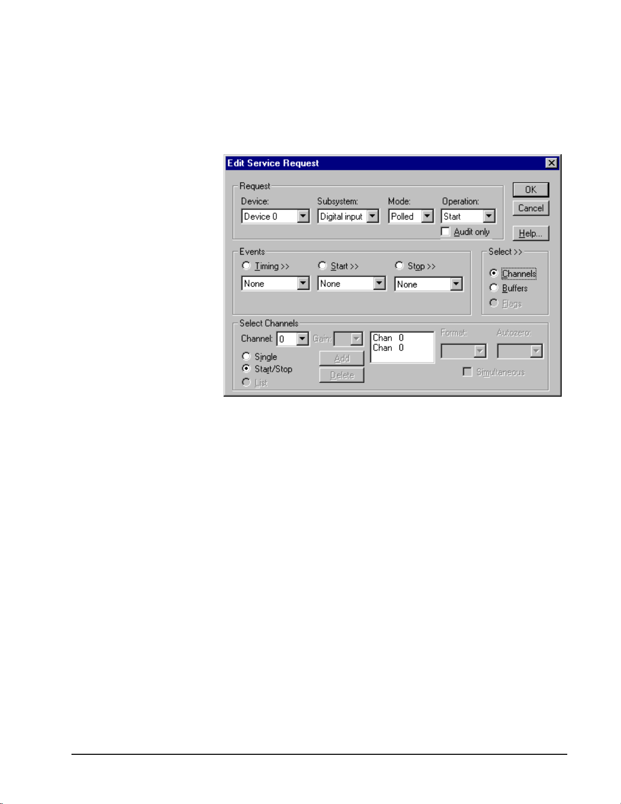
Multi-channel Digital Input Range
Even though the KPCI-1800
Series has only one digital
input channel, DriverLINX
supports specifying a channel
range for compatibility with
applications that use this
method.
In multi-channel range mode, the KPCI-1800 Series acquires all data from a
consecutive range of digital channels.
• The Start and Stop Channel must specify channel 0.
How to set up the KPCI-1800 S eri es for sampling on a consecutiv e range of channels.
Even though the KPCI-1800
Series has only one digital
input channel, DriverLINX
supports specifying a channel
range for compatibility with
applications that use this
method
Multi-channel Digital Input List
In multi-channel list mode, the KPCI-1800 Series acquires all data from an arbitrary
list of digital channels.
• The channel list may contain only channel 0.
Keithley KPCI-1800 Series Using the KPCI-1800 Series with DriverLINX • 71
Page 72

How to set up the KPCI-1800 S eri es to read from an arbitrary list of channels.
Digital Input Buffers
DriverLINX supports single-value, single-scan and buffered digital input.
• For single-value input, specify the Number of buffers as 0. The buffer
for a single value is the ioValue property.
• For single-scan input, specify the Number of buffers as 1 and the
number of Samples as 1.
• For buffered input, specify the Number of buffers from 1 to 256 and
the number of Samples as desired.
72 • Using the KPCI-1800 Series with DriverLINX Keithley KPCI-1800 Series
Page 73

How to set up the KPCI-1800 S eri es to read digital samples using dat a buf fers.
Digital Input Messages
For digital input operations, DriverLINX can report the following messages to the
application:
DriverLINX
Message
Service Start DriverLINX has started the acquisition task.
Service Done DriverLINX has completed the acquisition task.
Critical Error DriverLINX has encountered an unexpected hardware
Explanation
or software condition.
DriverLINX Event mess age f or di gi tal input
Keithley KPCI-1800 Series Using the KPCI-1800 Series with DriverLINX • 73
Page 74

Digital Output Subsystem
The following sections describe how DriverLINX implements Digital Output
Subsystem features for the KPCI-1800 Series.
Digital Output Modes
The Digital Output Subsystem supports the following modes:
• Polled—For single-value or scan digital-output samples.
• Interrupt—For buffered transfers using programmed I/O.
• Other—For subsystem initialization.
Digital Output Operations
The KPCI-1800 Series Digital Output Subsystem supports the following DriverLINX
operations:
• Initialize—aborts any active interrupt data-acquisition tasks and stops
the clock. DriverLINX prevents one application from interfering with
another application’s data-acquisition tasks.
• Start—initiates a data-acquisition task using the Mode, Timing, Start,
and Stop Events, the Logical Channels, and the Buffers the application
specified in the Service Request.
• Status—reports the buffer position of the next sample that DriverLINX
will read from a buffer.
• Stop—terminates a digital output data-acquisition task.
• Message—DriverLINX displays a pop-up dialog box for the user
containing the text for the current DriverLINX error message.
Digital Output Initialization
By default, the Digital Output subsystem writes zero into the digital output port. You
can specify a different initial output value using the Configure DriverLINX Device
dialog. See “Digital Output Subsystem Page” on page 19.
Digital Output Timing Events
Timing Events specify how the hardware paces or clocks writing Digital Output
samples. DriverLINX uses the Timing Event to program when the KPCI-1800 Series
writes the next digital output sample from the port.
The KPCI-1800 Series supports the following Timing Events:
• None—Output requires no pacing as DriverLINX is writing only a
single value.
• Rate—The KPCI-1800 Series supports fixed rate writing using internal
and external clocks.
74 • Using the KPCI-1800 Series with DriverLINX Keithley KPCI-1800 Series
Page 75

None or Null Event
The Null Event specifies that the task does not need a clock to determine when to
write the next sample.
Rate Event
The KPCI-1800 Series supports only the Rate Generator mode for Rate Events for
digital output:
• Rate Generator—Generates a fixed rate clock with equal time
intervals between tics.
Rate Generator: Internal Clocking
An internally clocked Rate Generator produces a fixed rate clock with equal time
intervals between tics.
Period
Use an internally clocked rate generator when you want to write all digital output
samples at equally spaced time intervals.
How to set up the KPCI-1800 Series for fixed rate sampling us i ng an i nternal clock.
Keithley KPCI-1800 Series Using the KPCI-1800 Series with DriverLINX • 75
Page 76

property specifies the time interval between samples in tics,
For hardware independence,
specify the clock channel
using the symbolic constant,
DEFAULTTIMER, which
always maps to the default
Logical Channel for digital
output timing.
• Specify internal clocking using a Rate Generator on any available
Channel with any internal Clock source. See “Counter/Timer
Subsystem” on page 82 for a description of clock sources.
• The Period
where a tic period depends on the clock source. The minimum period is
1 tic. The maximum period is 4294967295 tics (
or 65535 tics (
) for the other channels. See “Counter/Timer
1216−
32
21
− ) for Channel 0
Subsystem” on page 82 for details.
• The Gate property specifies how the TGIN signal affects the operation
of the internal clock. Valid settings are Enabled, Disabled, and Hi
Level, Low Level, Low Edge and High Edge Enabled. See
“Counter/Timer Subsystem” on page 82 for a description of each Gate
setting.
Rate Generator: External Clocki ng
An externally clocke d Rate Generator produces a rate clock with unknown time
intervals between tics.
Period (ext clk)
Use an externally clocked rate generator when you want to synchronize digital input
samples with a recurrent external signal. In this mode you will need a separate
external clock tic for each analog sample you want to acquire.
76 • Using the KPCI-1800 Series with DriverLINX Keithley KPCI-1800 Series
How to set up the KPCI-1800 Series for fixed rate writ i ng using an external clock.
Page 77

Be sure that the external
clock source is TTL
compatible, 0 V minimum to
+5 V maximum!
• Specify external clocking using a Rate Generator on available
Channel with an External, External+, or External- Clock source.
See “Counter/Timer Subsystem” on page 82 for a description of clock
sources. For hardware-independence, you can specify the hardware
external clock channel by the symbolic constant, DI_EXTCLK.
• Users should connect the external clock signal to the XPCLK line.
• The Period value doesn’t affect the external clock frequency, but
DriverLINX requires a valid hardware value in case the application
requests a timebase operation and to optimize data transfer between the
driver and the application. Period is in tics, where a tic period depends
on the clock source. See “Counter/Timer Subsystem” on page 82 for
details.
• The Gate property specifies how the TGIN signal affects the operation
of the internal clock. Valid settings are Enabled, Disabled, and Hi
Level, Low Level, Low Edge and High Edge Enabled. See
“Counter/Timer Subsystem” on page 82 for a description of each Gate
setting.
Digital Output Start Events
Start Events specify when the KPCI-1800 Series hardware starts writing digital
output data.
The KPCI-1800 Series supports the following Start Events for digital output:
• None—Use this event when the DriverLINX operation doesn’t require
a Start Event.
• Command—DriverLINX starts the task on software command, i.e., as
soon as DriverLINX finishes programming the KPCI-1800 hardware
for the task.
None or Null Event
The Null Event specifies that the task does not need a Start Event to begin the task.
Command Event
The Command Event starts data acquisition as soon as DriverLINX has completed
programming the KPCI-1800 hardware with the task parameters.
Digital Output Stop Events
Stop Events specify when the KPCI-1800 Series hardware stops writing digital
output data.
The KPCI-1800 Series supports the following Stop Events for digital output:
• None—Use this event when the DriverLINX operation doesn’t require
a Stop Event.
• Terminal count—DriverLINX stops the task after the KPCI-1800
Series hardware has written all the data buffers once.
Keithley KPCI-1800 Series Using the KPCI-1800 Series with DriverLINX • 77
Page 78

None or Null Event
The Null Event specifies that the task does not need a Stop Event to end the task.
Terminal Count Event
The Terminal Count Event stops data acquisition after DriverLINX has written the
digital output data from all the data buffers once. Use terminal count when you want
to write a fixed amount of data.
Digital Output Channels
The KPCI-1800 Series allows applications to specify the digital channels using three
techniques:
• Start Channel—Acquire data from a single channel.
• Start/Stop Channel Range—Acquire data from a consecutive range of
channels.
• Channel List—Acquire data from a list of channels.
Digital Output Logical Channels
The KPCI-1800 Series has a single digital output port that DriverLINX designates as
channel 0.
Single Channel Digital Output
In single channel mode, the KPCI-1800 Series writes all data from one channel.
How to set up the KPCI-1800 S eri es for writing to a single c hannel .
78 • Using the KPCI-1800 Series with DriverLINX Keithley KPCI-1800 Series
Page 79

Multi-channel Digital Output Range
In multi-channel range mode, the KPCI-1800 Series acquires all data from a
consecutive range of digital channels.
• The Start and Stop Channel must specify channel 0.
How to set up the KPCI-1800 S eri es for writing to a consec utive range of channels.
Multi-channel Digital Output List
In multi-channel list mode, the KPCI-1800 Series acquires all data from an arbitrary
list of digital channels.
• The channel list may contain only channel 0.
Keithley KPCI-1800 Series Using the KPCI-1800 Series with DriverLINX • 79
Page 80

How to set up the KPCI-1800 S eri es to write to an arbitrary li st of channels.
80 • Using the KPCI-1800 Series with DriverLINX Keithley KPCI-1800 Series
Page 81

Digital Output Buffers
DriverLINX supports single-value, single-scan and buffered digital output.
• For single-value output, specify the Number of buffers as 0. The
buffer for a single value is the ioValue property.
• For single-scan output, specify the Number of buffers as 1 and the
number of Samples as 1.
• For buffered output, specify the Number of buffers from 1 to 256 and
the number of Samples as desired.
How to set up the KPCI-1800 S eri es to write digital output using data buffers.
Digital Output Messages
For digital output operations, DriverLINX can report the following messages to the
application:
DriverLINX
Message
Service Start DriverLINX has started the acquisition task.
Service Done DriverLINX has completed the acquisition task.
Buffer Filled DriverLINX has written all data in the buffer.
Data Lost DriverLINX has detected a digital output data overrun
Critical Error DriverLINX has encountered an unexpected hardware
Explanation
condition.
or software condition.
DriverLINX Event mess ages for digital output.
Keithley KPCI-1800 Series Using the KPCI-1800 Series with DriverLINX • 81
Page 82

Counter/Timer Subsystem
The KPCI-1800 Series provides counter/timers for analog and digital input/output
pacing only. You c annot use the Counter/Timer Subsystem for independent counting
or timing tasks.
Each board has an Intel 8254 Programmable Interval Timer that consists of three 16bit counters, Counter 0, Counter 1, and Counter 2. For flexibility and compatibility
with the DAS-1800 Series, DriverLINX operates Counters 1 and 2 in a 32-bit
cascaded configuration. Counter 0 is then available to pace a separate, concurrent
task. For pacing three concurrent tasks, DriverLINX maps Counters 1 and 2 in noncascaded mode as Logical Channels 2 and 3. Using Logical Channel 0 makes Logical
Channels 2 and 3 unavailable, and vice versa.
The KPCI-1800 Series has one gate and one external clock connection. You can use
the signal to control any of the four Logical Channels. See “Counter/Timer
Subsystem Signals” on page 30 for connection details.
The following table lists the Counter/Timer Subsystem’s Logical Channels and shows
their allowable clock sources, modes and gates:
82 • Using the KPCI-1800 Series with DriverLINX Keithley KPCI-1800 Series
Page 83

Clocks
Tic Period
10 µs
1 / c o n fig fr e q
Logical Channe ls
Source
0— 8 254 Chip Internal 1 1 / config freq R ate Gen Enabled
Counters 1 & 2 Internal 2 0 .1 µ s Burst Gen Disabled
Internal 3 0.2 µs No Conn ect
Default channel for Internal 4 1 µ s Low Level
Analog Input pacing Internal 5 10 µs Low Edge
Ex te r n al 1 / c o n fig fr e q Hig h L e ve l
External+ High Edge
External1— 8 254 Chip Internal 1 1 / config freq R ate Gen Enabled
Co u nte r 0 Inte rn al 2 0.1 µ s Bur st G e n D isab led
Internal 3 0.2 µs No Conn ect
Default channel for Internal 4 1 µ s Low Level
Analog Output Internal 5
pacing External 1 / config freq H igh Level
External+ High Edge
External2—8254 Chip Internal 1
Co u nte r 1 Inte rn al 2 0.1 µ s Bur st G e n D isab led
Internal 3 0.2 µs No Conn ect
Default channel for Internal 4 1 µ s Low Level
Digital Input pacing Internal 5 10 µ s Low E dge
Ex te r n al 1 / c o n fig fr e q Hig h L e ve l
External+ High Edge
External3— 8 254 Chip Internal 1 1 / config freq R ate Gen Enabled
Co u nte r 2 Inte rn al 2 0.1 µ s Bur st G e n D isab led
Internal 3 0.2 µs No Conn ect
Default channel for Internal 4 1 µ s Low Level
Digital Output pacing Internal 5 10 µs Low E dge
Ex te r n al 1 / c o n fig fr e q Hig h L e ve l
External+ High Edge
External-
Mo des G ates
Low Edge
Rate Gen Enabled
Counter/Timer Subsystem Logical Channels and Allowed Clocks, Modes and Gates.
For the Internal 1 and External clock sources, the tic period is the inverse of the
frequency of the default master clock source. The user sets default master clock
source on the Counter/Timer Subsystem Page of the DriverLINX Configuration
Panel. Applications can use the Sec2Tics function to determine the tic period of
Internal 1 or override the default clock source by selecting from Internal 2 to
Internal 5 as the clock source for a task.
Gate Settings
The Gate setting specifies how the TGIN signal affects the operation of the internal
or external clock. Valid settings are Enabled, Disabled, No Connect, and Hi Level,
Low Level, Low Edge a nd High Edge Ena bled.
• Enabled selects the gate’s default enabled mode. On the KPCI-1800
Series this is Hi Level.
Keithley KPCI-1800 Series Using the KPCI-1800 Series with DriverLINX • 83
Page 84

• Disabled allows the clock to pace samples independently of the gate
signal.
• No Connect specifies that the application does not need to enable or
disable the gate, so it can run on boards that do not have a gate or
enabled and disabled modes.
• Hi and Low Lev el allow the clock to pace samples only while the gate
signal is high or low, respectively.
• Low and Hi Edge are aliases for a digital start trigger. They enable the
clock after the first falling or rising edge, respectively.
84 • Using the KPCI-1800 Series with DriverLINX Keithley KPCI-1800 Series
Page 85

Uninstalling DriverLINX
How do I uninstall DriverLINX?
DriverLINX consists of three separate component installations:
• DriverLINX for Keithley KPCI-1800 Series
• DriverLINX Programming Interfaces
• DriverLINX Documentation
You can uninstall the last two installations at any time without interfering with
compiled applications that require DriverLINX drivers. To uninstall the latter
components, run the “Add/Remove Programs” tool in the Windows Control Panel.
To uninstall DriverLINX drivers for the Keithley KPCI-1800 Series, you must
• Disable the DriverLINX driver.
• Shut down your computer to remove the hard ware.
• Reboot your computer to unload the driver.
• Run the DriverLINX uninstall program.
How to Disable a DriverLINX Driver in Windows NT
1. From the Windows Start menu, select “Settings”, then “Control Panel”.
Left click on the DriverLINX Configuration icon in the Control Panel.
2. Select the KPCI-1800 devices you want to disable.
3. Right click on each device and select “Disabled” on the popup menu.
4. Repeat steps 2-3 for each KPCI-1800 card that you are uninstalling.
5. Close the DriverLINX Configuration Panel.
6. When finished, shut down your computer and physically remove any
installed KPCI-1800 hardware.
7. Reboot Windows.
8. To finish uninstalling, see “How to Remove DriverLINX for Keithley
KPCI-1800 Series” on page 86.
Keithley KPCI-1800 Series Uninstalling DriverLINX • 85
Page 86
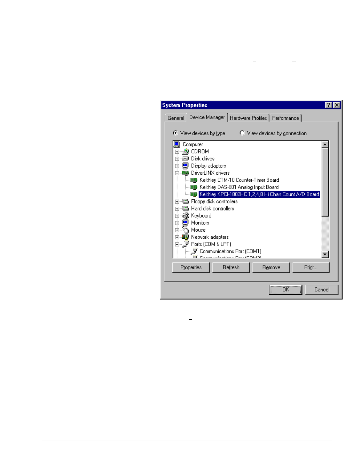
How to Disable a DriverLINX Driver in Windows 95/98
1. From the Windows Start menu, select “Settings”, then “Control Panel”.
Left click on the System icon in the Control Panel. Select the “Device
Manager” tab in the System Properties dialog.
2. Left click the “+” icon next to “DriverLINX drivers” to display the
installed Keithley KPCI-1800 devices.
3. Select the KPCI-1800 device you want to disable.
4. Click the “Re
5. In the “Confirm Device Removal” dialog, select “OK”.
6. Repeat steps 3-5 for each KPCI-1800 card or driver that you
uninstalling.
7. When finished, click “Close”, shut down your computer, and physically
remove any installed KPCI-1800 hardware.
8. Reboot Windows.
9. To finish uninstalling, see “How to Remove DriverLINX for Keithley
KPCI-1800 Series” on page 86.
move” button.
How to Remove DriverLINX for Keithley KPCI-1800 Series
1. From the Windows Start menu, select “Settings”, then “Control Panel”.
Left click on the Add/Remove Programs icon in the Control Panel.
86 • Uninstalling DriverLINX Keithley KPCI-1800 Series
Page 87

2. Select “DriverLINX for Keithley KPCI-1800 Series” in the
Add/Remove Programs Properties dialog.
3. Click the “Add/Remove…” button.
4. Answer “Y
es” to “Are you sure you want to remove ‘DriverLINX for
Keithley KPCI-1800 Series’ and all of its components?” in the Confirm
File Deletion dialog.
5. The DriverLINX uninstall program will proceed.
The uninstall program will not remove the folder, “\DrvLINX4\System”. This folder
contains copies of any \Windows\System or \Windows\System32 files that the
original DriverLINX installation updated.
Keithley KPCI-1800 Series Uninstalling DriverLINX • 87
Page 88

Page 89

Troubleshooting
Solving Problems
Correct operation of your KPCI-1800 hardware requires successful completion of
three steps.
1. Windows recognizes KPCI-1800 hardware and installs drivers.
2. You configure the KPCI-1800 drivers using the DriverLINX
Configuration Panel.
3. Windows loads the KPCI-1800 drivers into memory.
If you are having a problem installing or configuring your KPCI-1800 product,
review the following notes. If these notes do not solve your problem, or your problem
is not described, then contact technical support and fully describe your problem.
Solving Problems Recognizing and Installing
Drivers
Windows must recognize the KPCI-1800 hardware and then install KPCI-1800
drivers for the hardware.
• For Windows to automatically recognize the KPCI-1800 hardware, you
must install a KPCI-1800 product into your machine and restart the
computer.
• For Windows to install KPCI-1800 drivers, you must install the KPCI1800 driver software on the DriverLINX CD.
If you installed the KPCI-1800 hardware before you installed the DriverLINX
software, Windows 95/98 may install the KPCI-1800 hardware without drivers. To
fix this, you must instruct Windows to reinstall the Plug-and-Play driver. Follow the
notes below for instructions.
Fixing Problems Installing Hardware Before Software on
Windows 95/98
If you installed the KPCI-1800 hardware before installing the DriverLINX software,
Windows 95/98 may install the hardware incorrectly.
1. Start Windows Device Manager.
Keithley KPCI-1800 Series Uninstalling DriverLINX • 95
Page 90

2. Search for “DriverLINX drivers”. If you do not see it, go to step 4.
3. Click on the “+” icon next to “DriverLINX drivers” and search for “PCI
Card”. If you find “PCI Card”, go to step 6, otherwise go to the next
step.
4. Search for “Other devices”. If you do not see it, go to “Editing the
Windows 95/98 Registry” on page 90.
5. Click on the “+” icon next to “Other devices” and search for “PCI
Card”. If you do not find it, go to “Editing the Windows 95/98
Registry” on page 90.
6. Select “PCI Card”.
7. Click “Remove” in the Device Manager.
8. Highlight “Comput er” in the Device Manager and cli ck “Refresh”.
9. Windows should re-install your hardware under “DriverLINX drivers”.
If this fails, see “Editing the Windows 95/98 Registry” on page 90.
10. Answer “Yes” to “Do you want to restart your computer now?”.
11. After rebooting your comput er, you must configure Dri verLINX. See
“Configuring the KPCI-1800 Series” on page 11.
Editing the Windows 95/98 Registry
Before trying to edit the Windows Registry, follow the instructions for “Fixing
Problems Installing Hardware Before Software on Windows 95/98” on page 89.
Caution: Incorrect or unintended changes to Registry can prevent Windows from
booting. A complete reinstall of Windows may be the only recovery option. For
safety, first make a backup copy of the Registry using the “Registry | Export
Registry File…” menu option in the Registry Editor. Then follow these
instructions carefully.
1. From the Windows “Start” menu, select “Run”, type “regedit” into the
Run dialog and click OK
2. Under “My Computer”, first click the “+” next to
“HKEY_LOCAL_MACHINE”.
3. Next click the “+” next to “Enum” and then “PCI”.
4. If you have a KPCI-1801HC, search for “VEN_11F3&DEV_1801” on
Win 95 or “VEN_11F3&DEV_1801&SUBSYS_00000000&REV_00”
on Win 98. If you have a KPCI-1802HC, search for
“VEN_11F3&DEV_1802” on Win 95 or
“VEN_11F3&DEV_1802&SUBSYS_00000000&REV_00” on Win
98.
5. If you find neither entry, no Registry edits are needed. Exit the Registry
Editor and quit these instructions.
6. If you find either entry, select it and then delete the key by selecting
“E
dit | Delete” from the Registry Editor menu. Answer “Yes” to “Are
you sure you want to delete this key?”
7. Install the DriverLINX software, if you have not previously done so,
and then reboot your machine.
96 • Uninstalling DriverLINX Keithley KPCI-1800 Series
Page 91

Solving Problems Configuring the Drivers
Windows automatically assigns hardware resources for the KPCI-1800 Series, but
you must still configure the KPCI-1800 drivers before using them. The DriverLINX
configuration only requires that you assign each KPCI-1800 product a unique
Logical Device number. And, on Windows NT, you must manually select the
hardware model of your KPCI-1800 board. See “Configuring the KPCI-1800 Series”
on page 11 for more information.
Solving Problems Loading Drivers
Before the KPCI-1800 drivers can load, you must
1. Install the DriverLINX software.
2. Install the KPCI-1800 hardware into your computer.
3. Configure DriverLINX.
4. Reboot your computer.
If you have not completed the above steps, please do so before proceeding.
On both Windows NT and Windows 95/98, the operating system will automatically
assign hardware resources to the KPCI-1800 cards. Automatic resource assignment
can fail sometimes on
• Older PCI computers.
• Computers with ISA cards installed.
• Computers with no free ha rdware resources .
• Computers running Windows NT 4.0 with a BIOS setting designating
the operating system as Plug-and-Play Aware.
Sorting through all possibilities can be a challenge due to the she e r number of
combinations of PCI hardware designs, PC plug-in boards, and versions of Windows.
The following sections will help you gather information about why a driver may have
failed to load. This information is essential for you or technical support to solve your
problem.
Did the DriverLINX Driver Load?
1. Run “DriverLINX Configuration” from Windows Contro l Panel.
2. Select the “DriverLINX” tab.
3. Click the “+” icon next to DriverLINX to expand the list of drivers, if
necessary.
4. Select “Keithley KPCI-1800 Series”. Click “+”, if necessary, to expand
the list.
5. Select the line with the number of the Logical Device you configured. If
the number does not exist on Windows NT or, on Windows 95/98, you
see only a hardware description, you did not configure the driver. See
“Configuring the KPCI-1800 Series” on page 11.
6. Click the “P
7. Do you see “Status: Device Loaded”? If not, did you reboot the
computer after configuring? If not, reboot now and repeat the above
Keithley KPCI-1800 Series Uninstalling DriverLINX • 95
roperties…” button and then select the “General” tab.
Page 92

steps.
8. If you rebooted the computer after configuring and Windows did not
load your device, see “Checking for Device Errors” on page 92.
Checking for Device Errors
When a DriverLINX kernel driver cannot load, it usually writes an explanation into
the system event log. You can view this log under Windows 95/98 or Windows NT
using the DriverLINX Event Viewer.
Windows 95/98 maintains additional driver information in the Device Manager. Also
see “Getting More Driver Information on Windows 95/98” on page 92.
1. Run “DriverLINX Event Viewer” from the DriverLINX folder.
2. Click on the “+” icon next to “DriverLINX” in the left panel.
3. Select the abbreviation for your driver.
4. Does the first line in the right panel show a current error?
5. Double click on the error line to see more detail and an explanatory
message.
6. If you cannot resolve the problem yourself, please provide this error
information when contacting technical support.
Getting More Driver Information on Windows 95/98
Windows 95/98 reports additional information about device status using the Device
Manager. To access this utility,
1. Right click on “My Computer” and then select “Pr
2. Select “Device Manager” and “View devices by t
3. Does “DriverLINX drivers” appear in the list? If not, see “Solving
Problems Recognizing and Installing Drivers” on page 89.
operties”.
ype
4. Click the “+” next to “DriverLINX drivers”.
5. Does your KPCI-1800 product appear in the list? If not, see “Solving
Problems Recognizing and Installing Drivers” on page 89.
6. Does the icon next to your KPCI-1800 product display an exclamation
point (!)? If no, Windows has loaded your KPCI-1800 driver.
96 • Uninstalling DriverLINX Keithley KPCI-1800 Series
Page 93

7. Select the line with the “!” and then click “Properties”.
8. The General tab will show the reason why the driver did not load.
9. The Resources tab will show if Windows detected an unresolvable
hardware conflict.
Getting More Driver Information on Windows NT
On Windows NT, the only reasons that a driver does not load are
• You did not install the driver software.
• You did not correctly configure the driver.
• You changed the driver startup parameters.
• Your BIOS setting designates the operating system as Plug-and-Play
aware. (Applies only to Window NT 4.0).
An incorrectly configured driver will report the reasons that it failed to load into the
Windows Event Log. See “Checking for Device Errors” on page 92 for more
information.
Under Windows NT 4.0, a Logical Device may not load because the operating
system does not always configure Plug-and-Play PCI devices properly. This may
result in unexpected or no Event Log entries. To work around this, set your
computer’s BIOS to configure Plug-and-Play devices before it starts the operating
system. On various computers the BIOS setting is called “Plug-and-Play Aware OS –
Disabled” or “Plug & Play OS – No”.
On Windows NT, DriverLINX drivers load automatically during system boot. An
administrator can change the startup command for any NT driver to either “manual”
or “disabled”.
1. Run “DriverLINX Configuration” from Windows Contro l Panel.
2. Select the “DriverLINX” tab.
3. Click the “+” icon next to DriverLINX to expand the list of drivers, if
necessary.
4. Select “Keithley KPCI-1800 Series”. Click “+”, if necessary, to expand
the list.
5. Select the line with the number of the Logical Device that did not load.
6. Right click the mouse to see a popup menu.
Keithley KPCI-1800 Series Uninstalling DriverLINX • 95
Page 94

7. Select “Automatic” to instruct Windows to load the driver the next time
you reboot.
Generating a DriverLINX Configuration Report
Your DriverLINX installation includes a troubleshooting tool that generates a report
of your DriverLINX configuration. If you call Technical Support, after reading
“Solving Problems” on page 89, they may ask you to generate and e-mail this report
to help you solve installation and configuration problems.
What is in the Report?
The troubleshooting tool analyzes your computer to obtain information about
DriverLINX and operating system software that would assist Technical Support in
troubleshooting a problem you are having. It i ncludes information on DriverLIN X
files, environment variables, registry entries, hardware and the operating system.
How do I Generate the Repor t?
You can easily generate the report by clicking this shortcut . Once the
troubleshooting tool generates the report, you will have the opportunity to review it
and make deletions, if desired, before e-mailing it to Technical Support. If you do not
have direct access to e-mail, you can save the report to a disk file and send a copy
later. A Technical Support engineer will guide you through these steps when you are
asked to send a report.
96 • Uninstalling DriverLINX Keithley KPCI-1800 Series
Page 95

Glossary of Terms
Bus mastering
Bus mastering is a mode that PCI devices use to perform DMA data transfers. Bus
mastering requires a compatible PCI device and motherboard. The KPCI-1800 Series
and most motherboards support bus mastering.
A/D
Abbreviation for Analog-to-Digital, a process that converts a continuous analog
signal into a discrete digital approximation of the analog signal.
ADC
Abbreviation for Analog-to-Digital Converter, the hardware that performs the A/D
conversion.
API
Abbreviation for Application Programming Interface. An API defines the syntax of
the data structures and functions of software services.
Buffer
A block of memory used to receive data from a data-acquisition device or to write
data to a data-acquisition device.
Clocking
A periodic pulse or signal that data-acquisition hardware uses to read or write the
next sample or block of samples. Also referred to as “pacing”.
D/A
Abbreviation for digital-to-analog, a process that converts a discrete digital value into
a continuous analog voltage representing that value.
DAC
Abbreviation for digital-to-analog converter, the hardware that performs the D/A
conversion process.
Glossary of Terms Generating a DriverLINX Configuration Report • F-95
Page 96

DMA
Abbreviation for Direct Memory Access, a technique where the system board can
transfer data between a device and memory without using the CPU. In the PC, a
standard chip on the system board controls the transfer.
Event
For DriverLINX, an event is the occurrence of a signal that clocks, starts, or stops a
data-acquisition task.
Gating
A signal that enables and disables another signal or data-acquisition task depending
on the value of the gate signal.
IRQ
Abbreviation for interrupt request. Peripheral hardware signals the CPU that it is
ready to transfer data.
ISA
Abbreviation for Industry Standard Architecture. A standard for the original IBM AT
bus specification that defines the bus structure, CPU and support chip architecture,
and the clock frequency of the ISA bus.
ISR
Abbreviation for interrupt service routine, the software function inside a device
driver that handles interrupt requests.
Logical Device
DriverLINX’s designation for a specific data-acquisition board inside your computer.
Messages
In Windows and DriverLINX, a message notifies the application about the state of a
process.
Modes
DriverLINX data-acquisition techniques.
Operations
Allowed DriverLINX data-acquisition commands.
Pacing
A periodic pulse or signal that data-acquisition hardware uses to read or write the
next sample or block of samples. Also referred to as “clocking”.
96 • Generating a DriverLINX Configuration Report How do I Generate the Report?
Page 97

Process
Refers to the collection of data and code segments and hardware resources that the
operating system assigns to one application.
Service Request
A DriverLINX object or data structure that completely defines a data-acquisition
task.
Subsystem
DriverLINX subdivides a general purpose data-acquisition device into six
subsystems—Device, Analog Input, Analog Output, Digital Input, Digital Output,
and Counter/Timer.
Triggering
The technique of using a pulse or signal to start or stop a data-acquisition task.
TTL
Abbreviation for transistor-transistor logic, a family of digital logic elements.
Glossary of Terms Generating a DriverLINX Configuration Report • F-97
 Loading...